1
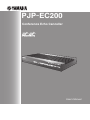
PJP-EC200
Conference Echo Canceller
User's Manual
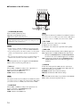
Caution: Read This before Operating Your Unit.
1
2
3
4
5
6
7
8
9
10
11
12
13
14
15
16
17
18
19
20
21
22
2
To assure the finest performance, please read this manual
carefully. Keep it in a safe place for future reference.
Only voltage specified on this unit must be used. Using this unit
with a higher voltage than specified is dangerous and may cause
fire, damage to this unit, and/or personal injury. Yamaha will not
be held responsible for any damage resulting from use of this unit
with a voltage other than specified.
When using the unit with an AC adapter, be sure to use the
dedicated adapter (PJP-PS02). Using other AC adapter may
cause an electrical shock, fire, and/or damage to this unit.
When using the unit for a long time, the unit may become warm.
Disconnect the cables, then leave the unit alone for cooling.
When not planning to use this unit for long periods of time (i.e.
vacation), disconnect the AC power plug from the wall outlet.
Do not plug in this unit to a wall outlet until all connections are
complete.
To prevent damage by lightning, keep the cables disconnected
during a lightning storm.
Do not use force on the power cable to prevent a fire, electrical
shock, damage to this unit, short circuit, and/or disconnection.
When disconnecting the power cable from the wall outlet, grasp
the plug: do not pull the cable.
Install this unit near the wall outlet and where the AC plugs can
be reached easily.
Do not cover this unit with a newspaper, tablecloth, curtain, etc.
in order not to obstruct heat radiation. If the temperature inside
this unit rises, it may cause fire, damage to this unit, and/or
personal injury.
Do not install this product upside down or in upright position.
Install the product on a stable, flat surface by orienting it
horizontally.
Do not install this product near television sets and/or wireless
devices to prevent operation failure caused by electromagnetic
waves and/or magnetism.
Locate this unit away from other electrical appliances, motors, or
transformers to avoid humming sounds.
Avoid installing this unit where foreign object may fall onto this
unit and/or this unit may be exposed to liquid dripping or
splashing. On the top of this unit, do not place:
– Other components, as they may cause damage and/or
discoloration on the surface of this unit.
– Burning objects (i.e. candles), as they may cause fire, damage
to this unit, and/or personal injury.
– Containers with liquid in them, as they may fall and liquid
may cause electrical shock to the user and/or damage to this
unit.
Do not expose this unit to sudden temperature changes from cold
to hot, and do not locate this unit in an environment with high
humidity (i.e. a room with a humidifier) to prevent condensation
inside this unit, which may cause an electrical shock, fire,
damage to this unit, and/or personal injury.
Do not attempt to modify or fix this unit. Contact qualified
Yamaha service personnel when any service is needed.
Do not use force on switches, knobs, and/or cords.
Do not clean this unit with chemical solvents; this might damage
the finish. Use a clean, dry cloth.
Do not use this unit near persons with a heart pacemaker implant
or defibrillator implant.
When disposing this unit, comply with your local regulations.
This unit contains a coin-type lithium battery.
If the coin-type lithium battery is dead, contact your nearest
authorized Yamaha dealer or service center.
This unit is not disconnected from the AC power source as
long as it is connected to the AC wall outlet, even if this unit
itself is turned off. This state is called the standby mode. In
this state, this unit is designed to consume a very small quantity of power.
WARNING
TO REDUCE THE RISK OF FIRE OR ELECTRIC SHOCK,
DO NOT EXPOSE THIS UNIT TO RAIN OR MOISTURE.
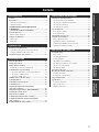
Contents
OPERATIONAL MANAGEMENT
Maintenance and Management .............................................. 35
Introduction ................................................................................4
Checking configurations and status ....................................... 35
Check the latest information.....................................................4
Checking the configuration information................................ 35
About this manual ....................................................................4
Checking the system logs ...................................................... 38
CONFIRMATION SOFTWARE LICENSE
AGREEMENT............................................................................5
Special Functions ..................................................................... 44
SOFTWARE LICENSE AGREEMENT .................................5
Protecting the settings............................................................ 44
Checking the error history ..................................................... 41
About the Product ......................................................................7
Restarting this unit ................................................................. 45
Enhanced basic functions .........................................................7
Changing the Screen Color..................................................... 46
Controls and Functions..............................................................8
Using the Latest Features........................................................ 47
Front panel................................................................................8
Flow of Firmware Update...................................................... 47
Rear panel.................................................................................9
Updating the firmware automatically .................................... 47
PREPARATION
Contents ......................................................................................3
INTRODUCTION
INTRODUCTION
Configuring the HTTP revision-up settings........................... 48
PREPARATION
Updating the firmware manually ........................................... 49
Connecting a microphone and speakers directly....................11
ADDITIONAL INFORMATION
Using in combination with a PA system ................................13
Troubleshooting ....................................................................... 50
Automatic Setup by Auto Analyzer........................................15
Basic check ............................................................................ 50
Checking the LED status ....................................................... 50
CONFIGURATIONS
Solving problems ................................................................... 50
Q1: LEDs are off or blinking................................................. 51
Setting the Password ................................................................17
Q2: Web menu settings are not available .............................. 52
Setting the Date and Time .......................................................18
Q3: Have an audio problem ................................................... 53
Setting the date and time automatically .................................19
Q4: Other problems ............................................................... 54
Configuring the Network Settings ..........................................21
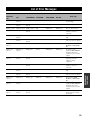
List of Error Messages ............................................................ 55
1. Specifying an IP address of this unit's LAN port ...............21
Resetting the Settings of This Unit......................................... 56
2. Specifying a default gateway .............................................22
Resetting all settings .............................................................. 56
Resetting the network settings ............................................... 56
Limiting Access to the Web Menu..........................................24
Support Information ............................................................... 57
Controlling Echoes ...................................................................25
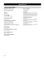
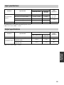
Specifications............................................................................ 58
Controlling Acoustic Feedback...............................................26
General specifications............................................................ 58
Controlling Noises ....................................................................27
Input specifications ................................................................ 59
Adjusting the Input Gain Automatically
(Auto Gain Controller) ............................................................28
Output specifications ............................................................. 59
Adjusting the Input Gain for MIC/LINE INPUT.................29
Adjusting the Volume Level....................................................30
Using the Internal Mixer .........................................................31
Configuring the Phantom Power Settings..............................32
Configuring This Unit's Settings Automatically
(Auto Analyzer) ........................................................................33
Turning On/Off the Audio Guidance .....................................34
3
ADDITIONAL
INFORMATION
3. Specifying a DNS server ....................................................23
OPERATIONAL
MANAGEMENT
Using the Web Menu................................................................16
CONFIGURATIONS
Installation and Initial Setup...................................................11
Introduction
Thank you for purchasing Yamaha PJP-EC200.
Before operating this unit, please read this manual carefully.
For your safety, please read all safety instructions and precautions stated in this manual carefully and keep it in a safe
place for future reference.
Check the latest information
This manual has been compiled based on the latest version of the firmware as of September 2009. For the latest
information about this unit, please visit the following website.
■Projectphone website
http://www.yamaha.co.jp/english/product/projectphone/
For the updating procedure, refer to “Using the Latest Features” (page 47) in this manual.
About this manual
■About abbreviations
In this manual, the product names are described as follows.
• Yamaha PJP-EC200: this unit
• Yamaha Projectphone: PJP
• Microsoft® Windows®: Windows
■About detailed technical information
Detailed knowledge on the professional audio (PA) system, Internet and network may be required to utilize this unit at its
full performance. As the provided manual does not give detailed technical information, please also refer to commercially
available books as required.
■About trademarks
• Ethernet is a registered trademark of Xerox Corporation.
• Microsoft and Windows are registered trademarks of Microsoft Corporation in the United States and other countries.
• No part of this document may be copied or used in any form without permission of Yamaha.
• Specifications of this unit or the web menu and contents of this document are subject to change without notice.
• Yamaha does not accept any liability for any loss or damage resulting from any use of this unit. The warranty covers a repair of this unit
only.
4
CONFIRMATION SOFTWARE LICENSE AGREEMENT
SOFTWARE LICENSE AGREEMENT
This License Agreement (the "AGREEMENT") is a legal agreement between you and Yamaha Corporation
("YAMAHA") under which YAMAHA is providing the firmware of YAMAHA's Projectphone™ (the "PRODUCT") and
related software program, documentation and electronic files (collectively, the "SOFTWARE").
This AGREEMENT applies to the SOFTWARE which YAMAHA provides you and the installed copy thereof, subject to
the provision of 1-1 herein, into the PRODUCT or personal computer owned by you.
1. GRANT OF LICENSE:
1-1. YAMAHA grants you a personal non-exclusive license to install the SOFTWARE and use the SOFTWARE on the
PRODUCT or other devices, including but not limited to the personal computer, which you own.
1-2. You shall not assign, sublicense, sell, rent, lease, loan, convey or otherwise transfer to any third party, upload to a
web site or a server computer to which specified or unspecified persons may access, or copy, duplicate, translate or
convert to another programming language the SOFTWARE except as expressly provided herein. You shall not alter,
modify, disassemble, decompile or otherwise reverse engineer the SOFTWARE and you also shall not have any third
party to do so.
1-3. You shall not modify, remove or delete a copyright notice of YAMAHA contained in the SOFTWARE.
1-4. Except as expressly provided herein, no license or right, express or implied, is hereby conveyed or granted by
YAMAHA to you for any intellectual property of YAMAHA.
2. OWNERSHIP AND COPYRIGHT:
The SOFTWARE is protected under the copyright laws and owned by YAMAHA. You agree and acknowledge that
YAMAHA transfers neither ownership interest nor intellectual property in the SOFTWARE to you under this
AGREEMENT or otherwise.
3. EXPORT RESTRICTIONS:
You agree to comply with all applicable export control laws and regulations of the country involved, and not to export or
re-export, directly or indirectly, the SOFTWARE in violation of any such laws and regulations.
4. SUPPORT AND UPDATE:
YAMAHA, YAMAHA's subsidiaries and affiliates, their distributors and dealers are not responsible for maintaining or
helping you to use the SOFTWARE. No updates, bug-fixes or support will be made available to you for the SOFTWARE.
5. DISCLAIMER OF WARRANTY:
5-1. THE SOFTWARE IS PROVIDED "AS IS" WITHOUT WARRANTY OF ANY KIND, EITHER EXPRESS OR
IMPLIED, INCLUDING, BUT NOT LIMITED TO THE IMPLIED WARRANTIES OF MERCHANTABILITY
AND FITNESS FOR A PARTICULAR PURPOSE.
5-2. IN NO EVENT SHALL YAMAHA, YAMAHA'S SUBSIDIARIES AND AFFILIATES, THEIR DISTRIBUTORS
AND DEALERS BE LIABLE FOR ANY DAMAGES WHATSOEVER (INCLUDING WITHOUT LIMITATION,
LOSS OF BUSINESS PROFITS, LOSS OF BUSINESS INFORMATION, LOSS OF BUSINESS INTERRUPTION
OR OTHER INCIDENTAL OR CONSEQUENTIAL DAMAGES) ARISING OUT OF THE SOFTWARE, USE
THEREOF, OR INABILITY TO USE THEREOF EVEN IF YAMAHA, YAMAHA'S SUBSIDIARIES AND
AFFILIATES, THEIR DISTRIBUTORS OR DEALERS HAVE BEEN ADVISED OF THE POSSIBILITY OF
SUCH DAMAGES. SOME STATES DO NOT ALLOW THE LIMITATION OR EXCLUSION OF LIABILITY
FOR INCIDENTAL OR CONSEQUENTIAL DAMAGES, SO THE ABOVE LIMITATION OR EXCLUSION
MAY NOT APPLY TO YOU.
5-3. YAMAHA, YAMAHA'S SUBSIDIARIES AND AFFILIATES, THEIR DISTRIBUTORS AND DEALERS SHALL
HAVE NO OBLIGATION TO INDEMNIFY YOU AGAINST ANY CLAIM OR SUIT BROUGHT BY A THIRD
PARTY ALLEGING THAT THE SOFTWARE OR USE THEREOF INFRINGES ANY INTELLECTUAL
PROPERTY OF SUCH THIRD PARTY.
5
INTRODUCTION
BY USING THE "SOFTWARE", YOU ARE DEEMED TO AGREE TO BE BOUND BY THE TERMS AND
CONDITIONS OF THIS AGREEMENT.
6. TERM:
6-1. This AGREEMENT becomes effective upon your agreeing the terms and conditions herein and continues in effect
unless or until terminated in accordance with the provision of 6-2 or 6-3 herein.
6-2. You may terminate this AGREEMENT by deleting the SOFTWARE installed into the PRODUCT.
6-3. This AGREEMENT will also terminate if you fail to comply with any of the terms and conditions of this
AGREEMENT.
6-4. In case this AGREEMENT is terminated in accordance with the provision 6-3, you shall promptly delete the
SOFTWARE.
6-5. Notwithstanding anything contains herein, Sections 2 though 6 shall survive any termination or expiration hereof.
7. SEVERABILITY:
In the event that any provision of this AGREEMENT is declared or found to be illegal by any court or tribunal of
competent jurisdiction, such provision shall be null and void with respect to the jurisdiction of that court or tribunal and
all the remaining provisions of this AGREEMENT shall remain in full force and effect.
8. U.S. GOVERNMENT RESTRICTED RIGHTS NOTICE:
The Software is a "commercial item," as that term is defined at 48 C.F.R. 2.101 (Oct 1995), consisting of "commercial
computer software" and "commercial computer software documentation," as such terms are used in 48 C.F.R. 12.212
(Sept 1995). Consistent with 48 C.F.R. 12.212 and 48 C.F.R. 227.7202-1 through 227.72024 (June 1995), all U.S.
Government End Users shall acquire the Software with only those rights set forth herein.
9. ACKNOWLEDGMENT:
You agree that this AGREEMENT is the complete and exclusive statement of agreement between you and YAMAHA
concerning the subject matter hereof and supersedes all proposals or prior agreements, verbal or written, and any other
communications between you and the parties relating to the subject matter hereof. NO amendment to this AGREEMENT
shall be effective unless signed by a duly authorized representative of YAMAHA.
10. GOVERNING LAW:
This AGREEMENT shall be governed by and construed in accordance with the lows of Japan without reference to the
principles of conflict of laws.
6
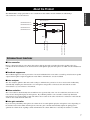
About the Product
INTRODUCTION
The PJP-EC200 is a high-performance echo canceller box that enables smooth simultaneous talk during a
videoconference or a webconference.
Echo canceller x 2
CONFERENCE OUT L
CONFERENCE OUT R
Mixer
CONFERENCE IN L
CONFERENCE IN R
Feedback suppressor x 2
MIC LINE INPUT IN2
MIC LINE INPUT IN1
LINE OUT R
LINE OUT L
Mixer
Enhanced basic functions
■Echo canceller
Echo is a phenomenon that occurs when microphones pick up the audio reproduced from the speakers. The echo
canceller of this unit eliminates echo elements from sounds picked up by the microphones to enable smooth simultaneous
talk.
■Feedback suppressor
The feedback suppressor detects generation of acoustic feedback which occurs when a sound loop exists between speaker
output and microphone input and applies the notch filter to minimize the acoustic feedback.
■Auto analyzer
The auto analyzer optimizes this unit's audio settings to minimize the generation of echoes and acoustic feedback by
automatically analyzing the characteristics of a microphone and speakers connected to this unit and the acoustic
characteristics of your conference environment.
■Noise reduction
The noise reduction automatically detects ambient noises (generated by a fan or an air conditioner) and removes the
noises from sounds picked up by the microphones. By combining with the echo canceller, it effectively eliminates
unwanted noises from the pickup sounds and delivers clear sounds to the other end. The noise reduction of this unit also
works on the sounds from the other end.
■Auto gain controller
If you are using a boundary microphone, the volume level of sounds picked up by the microphone varies depending on
the distance between the talker and microphone. The auto gain controller automatically adjusts the pickup gain to
optimize the volume level of pickup sounds and minimize the volume differences caused by the distance to a talker.
7
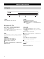
Controls and Functions
Front panel
MIC/LINE
IN1
INPUT LEVEL
IN2
①
CONFERENCE
PHANTOM
CONFERENCE ECHO CANCELLER
PJP-EC200
ACTIVE
GAIN KNOB
POWER
DIP SW
②
1 LEDs
2 Label
Light to indicate the status of this unit.
The following information is shown.
• MODEL No.: Model number of this unit
• SER.: Serial number for use in management/distinction
of this unit
■Functions of the LEDs
INPUT LEVEL (IN1/IN2 /CONFERENCE)
GAIN KNOB
On (green): Detecting audio data.
On (red): Audio is distorted because the input level is too
high.
Off: No audio data has been detected.
On: The MIC/LINE INPUT gain setting on this unit is
working.
Off: The MIC/LINE INPUT gain setting on the web menu
is working.
Blinks: The setting is not reflected.
Note
y
If the setting is not reflected, refer to “Q1: LEDs are off or
blinking” (page 51).
If this LED lights up in red, adjust the input gain for MIC/LINE
INPUT using the GAIN controls on the rear panel of this unit
until it turns off.
PHANTOM
On: The phantom power supply is on.
Off: The phantom power supply is off.
Blinks: The setting is not reflected.
y
If the setting is not reflected, refer to “Q1: LEDs are off or
blinking” (page 51).
DIP SW
On: The DIP switch settings are prioritized.
Off: The web menu settings are prioritized.
Blinks: The setting is not reflected.
y
If the setting is not reflected, refer to “Q1: LEDs are off or
blinking” (page 51).
POWER
On: The power of this unit is on.
Off: The power of this unit is off.
8
IN1 & 2
CONF.OUT
EC TYPE
MIX & FS
DIP SW
SETTING
PHANTOM
ON OFF
ETHER
LINE OUTPUT
CONFERENCE
STANDBY ON
MIC/LINE INPUT
IN2
R
L
OUT
IN
INTRODUCTION
AUTO
ANALYZER
MIC LINE
MIC LINE
2
1
ON OFF
ETHER
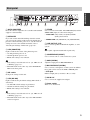
Rear panel
IN1
GAIN
INITIALIZE
PHANTOM
ACTIVE
①②
③
MIN
MAX MIN
IN2
DIP SW
MAX
IN1
DC IN 12V
ACTIVE
④ ⑤⑥
⑦
⑧
1 AUTO ANALYZER
Press this switch to adjust the echo canceller and feedback
suppressor automatically.
2 INITIALIZE
If you turn on this unit while holding down this switch,
you can reset the settings of this unit to the default. If you
press this switch when the power is on, only the network
settings are reset to the default. For details, refer to
“Resetting the Settings of This Unit” (page 56)".
3 LED (PHANTOM)
Lights to indicate the status of the phantom power.
• On: The phantom power is on.
• Off: The phantom power is off.
• Blinks: The setting is not reflected.
y
• If the setting is not reflected, refer to “Q1: LEDs are off
or blinking” (page 51)".
• This LED works in the same way as the PHANTOM
LED on the front panel.
4 DIP switch
Changes the settings of this unit.
5 LED (DIP SW)
Lights to indicate the prioritized settings (DIP switch or
web menu).
• On: The DIP switch settings are prioritized.
⑨
⑩
⑪
⑫
6 ETHER
Use to connect a LAN cable. The LINK LED (left) and the
SPEED LED (right) are above the LAN port.
• LINK LED: Off (no link), On (linked), Blinks
(during data transfer)
• SPEED LED: Off (10BASE-T), On (100BASE-TX)
7 LINE OUTPUT (L/R)
Use to connect speakers with built-in amplifier, or a PA
system.
y
These jacks output monaural audio signals only.
8 CONFERENCE (IN/OUT)
Use to connect a PC or a videoconference system.
9 GAIN (IN1/IN2)
Adjust the input gain for MIC/LINE INPUT.
0 MIC/LINE INPUT (IN1/IN2)
Use to connect a microphone or a PA system. In addition,
these jacks can be used as the XLR or PHONE jacks.
• XLR jack
Balanced input jack (1: Ground, 2: Hot, 3: Cold)
A DC IN 12V
Use to connect the supplied AC adapter.
B Power switch
Turns on or off this unit.
• Off: The web menu settings are prioritized.
• Blinks: The setting is not reflected.
y
• If the setting is not reflected, refer to “Q1: LEDs are off
or blinking” (page 51).
• This LED works in the same way as the DIP SW LED
on the front panel.
9
■Functions of the DIP switch
SETTING
PHANTOM
IN1 & 2
CONF.OUT
EC TYPE
MIX & FS
DIP SW
ON OFF
MIC LINE
MIC LINE
2
1
ON OFF
ETHER
①②③④⑤⑥
1 PHANTOM (DC+48V)
Turns on/off the phantom power.
ON: Turn on the phantom power.
OFF: Turns off the phantom power.
Make sure you set this switch to OFF when a device which does not
require a phantom power is connected. Incorrect settings may cause
a malfunction of the external devices.
Notes
• Set this switch to ON when an XLR-type microphone which
requires a phantom power is connected to MIC/LINE INPUT.
• To protect the speakers, turn off the speakers or set the speaker
volume to the minimum before turning on/off the phantom
power.
• For your safety, the phantom power is not supplied unless it is
enabled on the web menu even if this switch is set to ON.
y
While the phantom power is supplied, the PHANTOM
LEDs on the front and rear panels turn on.
Note
The signal level differs between MIC level and LINE level. When
you connect a device to a MIC jack, set this switch to MIC. When
you connect a device to a LINE jack, set this switch to LINE.
4 EC TYPE
Sets the effectiveness of the echo canceller.
2: Higher the echo reduction.
1: Lower the echo reduction to prioritize audio quality.
5 MIX & FS
Turns on/off the internal mixing and feedback suppressor.
ON: Output audio to LINE OUTPUT after audio input
through CONFERENCE IN and MIC/LINE INPUT
are mixed. Also, the feedback suppressor is enabled.
OFF: Output audio input through CONFERENCE IN to
LINE OUTPUT. Also, the feedback suppressor is
disabled.
6 DIP SW
2 IN1 & 2
Selects MIC or LINE according to the output level of
devices connected to MIC/LINE INPUT.
MIC: Switch to the MIC level.
LINE: Switch to the LINE level.
Note
The signal level differs between MIC level and LINE level. When
you connect a device to a MIC jack, set this switch to MIC. When
you connect a device to a LINE jack, set this switch to LINE.
3 CONF.OUT
Selects MIC or LINE according to the input level of a
device connected to CONFERENCE OUT.
MIC: Switch to the MIC level.
LINE: Switch to the LINE level.
10
Selects the setting priority (DIP switch or web menu).
Setting items that are not available by the DIP switch are
always decided by the web menu.
ETHER: Prioritize the web menu settings.
DIP SW: Prioritize the DIP switch settings.
y
While the DIP switch settings are prioritized, the DIP SW
LEDs on the front and rear panels turn on.
Installation and Initial Setup
This section describes connections and setup required for using this unit. The basic setup of this unit is available only
with the DIP switch. For advanced setup, refer to “Using the Web Menu” (page 16).
Notes
• Do not use the mute function on a microphone or PA system connected to this unit to prevent echo generations on the other end.
• Make sure all devices are turned off before connecting a microphone or speakers. Moreover, make sure the microphone and speaker
volumes of all devices are set to the minimum.
• To minimize echo or acoustic feedback, maintain an appropriate distance between the microphone and speakers.
PREPARATION
• When connecting external devices, refer to the owner's manual supplied with each device in addition.
• Be sure to use the AC adapter and power cable supplied with this unit.
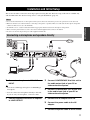
Connecting a microphone and speakers directly
1
ETHER
SETTING
PHANTOM
IN1 & 2
CONF.OUT
EC TYPE
MIX & FS
DIP SW
13
ON OFF
AUTO
ANALYZER
MIC LINE
MIC LINE
2
1
ON OFF
ETHER
2
LINE OUTPUT
CONFERENCE
STANDBY ON
MIC/LINE INPUT
IN2
R
L
OUT
10
IN
IN1
GAIN
INITIALIZE
PHANTOM
ACTIVE
MIN
DIP SW
MAX MIN
IN2
MAX
IN1
DC IN 12V
ACTIVE
12
8
5
7
4
6
3
1 Connect a microphone to MIC LINE
INPUT.
3 Connect CONFERENCE IN of this unit to
the audio output jack of your PC or
videoconference system.
y
• You can use a XLR-type microphone or PHONE-type
microphone.
4 Connect CONFERENCE OUT of this unit
• You can connect two microphones directly to this unit.
If you use only one microphone, connect it to IN1.
to the audio input jack of your PC or
videoconference system.
2 Connect speakers with built-in amplifier
5 Connect the AC adapter to DC IN.
to LINE OUTPUT.
6 Connect the power cable to the AC
adapter.
7 Connect the power cable to an AC outlet.
11
8 Configure the settings of this unit using
the DIP switch.
For details, refer to “Functions of the DIP switch”
(page 10).
9 Turn on the external devices.
10 Turn on this unit.
The POWER LED on the front panel turns on.
11 On your PC or videoconference system,
adjust the output level.
Adjust the output level so that the INPUT LEVEL
LED on the front panel does not turn on in red.
12 Use GAIN to adjust the input gain for
MIC/LINE INPUT.
Adjust the input gain so that the INPUT LEVEL LED
on the front panel does not turn on in red.
13 Press AUTO ANALYZER.
The echo canceller and feedback suppressor settings
are automatically adjusted. For details, refer to
“Automatic Setup by Auto Analyzer” (page 15).
Notes
• If you do not connect a microphone to MIC/LINE INPUT IN2,
set GAIN IN2 to the minimum.
• Set the microphone and speaker volumes to the minimum
before turning off this unit.
12
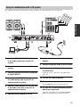
Using in combination with a PA system
By combining this unit with a PA system, it makes possible to use many microphones for a conference.
2
PREPARATION
13
IN1 & 2
CONF.OUT
EC TYPE
MIX & FS
DIP SW
ETHER
SETTING
PHANTOM
15
ON OFF
AUTO
ANALYZER
MIC LINE
MIC LINE
2
1
ON OFF
ETHER
3
1
LINE OUTPUT
CONFERENCE
IN2
R
L
OUT
11
STANDBY ON
MIC/LINE INPUT
IN
IN1
GAIN
INITIALIZE
PHANTOM
ACTIVE
MIN
DIP SW
MAX MIN
IN2
MAX
IN1
ACTIVE
9
14
DC IN 12V
6
8
5
7
4
1 Connect MIC/LINE INPUT IN1 of this unit
to the audio output jack of your PA
system.
7 Connect the power cable to the AC
adapter.
8 Connect the power cable to an AC outlet.
2 Connect microphones to your PA
system.
9 Configure the settings of this unit using
the DIP switch.
3 Connect speakers with built-in amplifier
to LINE OUTPUT.
4 Connect CONFERENCE IN of this unit to
the audio output jack of your PC or
videoconference system.
For details, refer to “Functions of the DIP switch”
(page 10).
10 Turn on the external devices.
11 Turn on this unit.
The POWER LED on the front panel turns on.
5 Connect CONFERENCE OUT of this unit
to the audio input jack of your PC or
videoconference system.
6 Connect the AC adapter to DC IN.
12 On your PC or videoconference system,
adjust the output level.
Adjust the output level so that the INPUT LEVEL
LED on the front panel does not turn on in red.
13
13 On your PA system, adjust the input
gain.
For details, refer to the owner's manual supplied with
your PA system.
14 Use GAIN to adjust the input gain for
MIC/LINE INPUT.
Adjust the input gain so that the INPUT LEVEL LED
on the front panel does not turn on in red.
15 Press AUTO ANALYZER.
The echo canceller and feedback suppressor settings
are automatically adjusted. For details, refer to
“Automatic Setup by Auto Analyzer” (page 15).
Notes
• If you do not connect a microphone or a PA system to MIC/
LINE INPUT IN2, set GAIN IN2 to the minimum.
• Set the microphone and speaker volumes to the minimum
before turning off this unit.
14
Automatic Setup by Auto Analyzer
The auto analyzer function automatically sets the echo
canceller and feedback suppressor settings best suited for
your environment (types of microphone and speakers, size
of conference room, etc.).
Note
• During the measurement, the microphone picks up test tones
output from the speakers. To achieve the best results, keep the
room as quiet as possible during the measurement.
• Since this unit measures MIC/LINE INPUT IN 1 and IN2
individually, this unit proceeds in the next step if any of
measurements are successful. In case any measurement is
failed, this unit will notify you of the status of the channel after
the acoustic analysis.
If a measurement is failed
y
You can turn off the audio guidance which notifies you of
events during the auto analyzer process. For details, refer
to “Turning On/Off the Audio Guidance” (page 34).
■Before starting the auto analyzer
To achieve the best results, carry out the following
procedures before starting the auto analyzer.
• Install the microphone and speakers at places where
they will be located during a conference.
• Adjust the speaker volume to an appropriate level for a
conference.
• Adjust the input gain for MIC/LINE INPUT so that the
INPUT LEVEL LED does not turn on in red.
• Set whether audio input through MIC/LINE is output to
LINE OUT.
1 The auto analyzer starts.
By pressing AUTO ANALYZER, this unit outputs a
long beep to indicate the start of the auto analyzer
process and then plays back the audio guidance.
y
To quit the auto analyzer, press AUTO ANALYZE again.
2 Test tones are output.
This unit outputs test tones used for measuring your
acoustic environment. Since this unit measures MIC/
LINE INPUT IN 1 and IN2 individually, test tones
are output twice. The INPUT LEVEL LEDs on the
front panel blink during the measurement.
The auto analyzer quits. This unit outputs short beeps to
indicate an abnormal end and then plays back the audio
guidance which explains the cause of the error.
3 The acoustic analysis starts.
This unit analyzes your acoustic environment and
then optimizes the echo canceller and feedback
suppressor settings automatically. The INPUT
LEVEL LEDs on the front panel blink in a direction
from right to left during the analysis.
y
The analysis time varies depending on your environment
(types of microphone and speakers, size of conference
room, etc.).
4 The auto analyzer ends.
This unit outputs a short beep to indicate a normal
end or short beeps to indicate an abnormal end and
then plays back the audio guidance which explains
the result. Also, the front panel LEDs indicate the
result of the auto analyzer.
Note
If you move the microphone or speakers, the current settings
optimized by the auto analyzer may lose effectiveness or increase
the generation of echo or acoustic feedback. In this case, run the
auto analyzer again.
If you cannot feel the effectiveness
Run the auto analyzer again. If you are using this unit in
an environment where echo or acoustic feedback is rarely
generated, it may be difficult to feel the effectiveness. In
this case, you do not need to run the auto analyzer again
since your environment is already suited for a conference.
If the auto analyzer abnormally ends
Follow the audio guidance or check the status of the front
panel LEDs to change the installation location. For details
on LED statuses, refer to “List of Error Messages”
(page 55).
15
PREPARATION
The auto analyzer configures the settings based on the relative
position of a microphone and speakers. It is effective when a fixed
microphone such as a gooseneck microphone and a boundary
microphone is used.
Notes
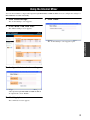
Using the Web Menu
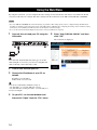
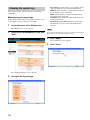
By using the web menu, you can configure this unit's settings in more detail. The web menu is accessible from the PC
connected to this unit. To configure this unit's settings from the web menu, set the DIP switch (DIP SW) to ETHER.
Notes
• If you set DIP SW to ETHER, the web menu settings are prioritized. The settings items you have configured using the DIP switch
should be reconfigured on the web menu. If you set the DIP switch to DIP SW after configuring the settings on the web menu, setting
items that are not available by the DIP switch are decided by the web menu settings.
• To access the web menu, Internet Explorer 6.0 (or later version) for Windows is required.
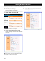
1 Connect this unit and your PC using the
LAN cable.
5 Enter "http://192.168.100.101" and then
click "OK".
PHANTOM
IN1 & 2
CONF.OUT
EC TYPE
MIX & FS
DIP SW
SETTING
ON OFF
MIC LINE
MIC LINE
2
1
ON OFF
ETHER
The web menu is displayed.
AUTO
ANALYZER
ETHER
LINE OUTPUT
CONFERENCE
STANDBY ON
MIC/LINE INPUT
IN2
R
L
OUT
IN
IN1
GAIN
INITIALIZE
PHANTOM
ACTIVE
MIN
DIP SW
MAX MIN
IN2
MAX
IN1
ACTIVE
DC IN 12V
y
Since this unit automatically detects the type of a LAN
cable (straight or crossover), you can use a straight LAN
cable to directly connect this unit to a PC.
2 Turn on this unit and your PC.
3 Change the IP address of your PC as
follows.
IP address: 192.168.100.2
Subnet mask: 255.255.255.0
y
You can use an IP address within the range of
"192.168.100.1" to "192.168.100.254" (except
"192.168.100.101"). In this procedure, "192.168.100.2" is
used as an example.
4 On your PC, run the web browser and
then select "Open" from the "File" menu.
16
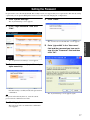
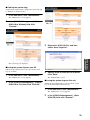
Setting the Password
No password is set to this unit by default. For security reasons, we suggest that you set a password to this unit. By setting
a password, you can prevent third parties from access to this unit and changing the configurations.
1 Click "System Settings".
5 Click "Close".
The "System Settings" screen appears.
2 In the "Login Password" field, click
"Edit".
The "Connect to 192.168.100.101" screen appears.
field and the password you have set in
step 3 in the "Password" field and then
click "OK".
The "Login Password Settings" screen appears.
3 Enter a new password (up to 32 one-byte
alpha-numerals).
New Password: Enter a desired password.
New Password (to confirm): Reenter the password for
confirmation.
The "System Settings" screen appears again.
y
If a password has already been set, enter the current
password in the "Old Password" field.
4 Click "Apply".
The new password is set and then the confirmation
screen appears.
17
CONFIGURATIONS
6 Enter "pjp-ec200" in the "User name"
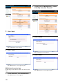
Setting the Date and Time
Follow the procedure below to set the date and time of this unit.
1 Click "System Settings".
The "System Settings" screen appears.
2 In the "Clock" field, click "Edit".
The "Clock Settings" screen appears.
3 In the "PJP-EC200 Date/Time" field,
select "Change" and then enter the date
and time.
y
To set the exact time, enter a time a little ahead and then
click "Apply" according to a time signal.
18
4 In the "Timezone" field, select the time
zone of your area.
If your area uses DST (Daylight Saving Time)
Select "Adjust clock for daylight saving changes" and then
configure the DST setting.
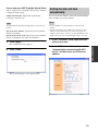
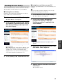
Setting the date and time
automatically
Adjust automatically: Adjust DST automatically
according to the time zone.
You can set the date and time of this unit automatically by
using an NTP server via the Internet.
Note
Notes
To adjust DST automatically, this unit must be connected to the
Internet.
• To use an NTP server, this unit must be connected to the
Internet.
Specify by date and time: Specify the period of DST in
month, day and time.
Specify by day of the week: Specify the period of DST in
month, week number, day of the week and time.
• You may not be able to use an NTP server due to the security
settings of your LAN. In this case, you need to change the
settings of your router to connect to an external NTP server. For
details, refer to the owner's manual supplied with your router.
1 In the "Timezone" field, select the time
5 Click "Apply".
zone of your area.
The confirmation screen appears.
6 Click "Close".
CONFIGURATIONS
2 In the "NTP Server" field, select
"Automatically synchronize with NTP
server" and then enter an NTP server
address.
The "System Settings" screen appears again.
19
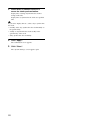
3 Select when to connect to the NTP
server for clock synchronization.
Inquiry time at startup: Synchronize the clock at
startup of this unit.
Inquiry time at: Synchronize the clock at a specified
time.
y
If you select "Inquiry time at", select a day to synchronize
the clock.
• monthly on the day: Synchronize the clock monthly on
the specified day.
• weekly on: Synchronize the clock weekly on the
specified day of the week.
• daily: Synchronize the clock daily.
4 Click "Apply".
The confirmation screen appears.
5 Click "Close".
The "System Settings" screen appears again.
20
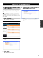
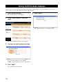
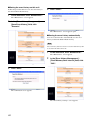
Configuring the Network Settings
1. Specifying an IP address of this
unit's LAN port
5 Click on the link to access to the new IP
address and then click "Close".
According to the LAN environment where this unit is
used, configure the IP address netmask settings of this
unit.
y
"192.168.100.101/24" is assigned to the LAN port by
default. If you want to change the IP address, use an IP
address which is not used by other external devices in the
same network.
1 Click "IP Settings".
The "IP Settings" screen appears.
The "Top Page" screen under the new IP address
appears.
CONFIGURATIONS
2 In the "LAN Port" field, click "Edit".
The "LAN Port Settings" screen appears.
3 Enter an IP address to assign to this
unit.
4 Click "Apply".
The confirmation screen appears.
21
2. Specifying a default gateway
5 Click "Close".
Follow the procedure below to specify a default gateway for
this unit.
1 Click "IP Settings".
The "IP Settings" screen appears.
2 In the "Default Gateway" field, click
"Edit".
The "IP Settings" screen appears again.
The "Default Gateway Settings" screen appears.
3 Select "Specify" and then enter the IP
address of the default gateway in the "IP
Address" field.
4 Click "Apply".
The confirmation screen appears.
22
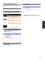
3. Specifying a DNS server
5 Click "Close".
Follow the procedure below to specify a DNS server for
this unit.
1 Click "IP Settings".
The "IP Settings" screen appears.
2 In the "DNS Server" field, click "Edit".
The "IP Settings" screen appears again.
CONFIGURATIONS
The "DNS Server Settings" screen appears.
3 Select "Specify" and then enter the IP
address of the DNS server in the "IP
Address" field.
4 Click "Apply".
The confirmation screen appears.
23
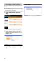
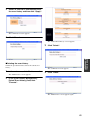
Limiting Access to the Web Menu
You can limit access to the web menu by PC's IP address or permit access to the web menu only from PCs in the same
network.
1 Click "System Settings".
The "System Settings" screen appears.
2 In the "HTTP Server" field, click "Edit".
4 Click "Apply".
The confirmation screen appears.
5 Click "Close".
The "System Settings" screen appears again.
The "HTTP Server Settings" screen appears.
3 Configure the access limitation settings.
Access Permission: Select an access condition from
"Permit all" (allow access from any address), "Same
segment" (allow access within the same network),
and "Permit specific host only" (allow access from
the specified IP address only).
Session Timeout: Specify a timeout period. You will
be logged out from the web menu if the specified
time passes after the last operation.
Display Name: Specify a name assigned to this unit.
To specify a name, select "Specify" and then enter a
desired name (up to 64 one-byte alpha-numerals).
24
Controlling Echoes
4 Click "Apply".
The confirmation screen appears.
5 Click "Close".
The "Echo Canceller Settings" screen appears.
3 Configure the echo canceller settings.
The "Sound Settings" screen appears again.
25
CONFIGURATIONS
Follow the procedure below to configure the echo reduction level according to your environment. You can configure the
settings for MIC/LINE IN1 and IN2 individually.
Use: Select whether to use the echo canceller. To use
the echo canceller, select "Enable".
1 Click "Sound Settings".
Level: Select an echo reduction level from "Low",
The "Sound Settings" screen appears.
"Middle" and "High". The higher the level, the higher
the echo reduction. The lower the level, the lower the
2 In the "Echo Canceller" field, click
echo reduction but higher the audio quality of
"Edit".
simultaneous two-way communications.
Mic/Sp Distance: Specify the distance (0 to 40 m)
between the microphone and speaker. If you are using
multiple microphones and speakers, specify the
distance between nearest pair.
Mic Type: Select the type of the connected
microphone. If the distance between the microphone
and speaker is variable, select "Hand Mic". If the
distance is fixed, select "Fixed Mic".
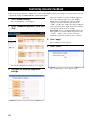
Controlling Acoustic Feedback
Follow the procedure below to configure the acoustic feedback reduction level according to your environment. You can
configure the settings for MIC/LINE IN1 and IN2 individually.
Use: Select whether to use the feedback suppressor.
To use the feedback suppressor, select "Enable".
1 Click "Sound Settings".
Level: Select a cutoff amount of the notch filter
The "Sound Settings" screen appears.
applied to acoustic feedback frequencies from
"-6dB", "-12 dB" and "-18dB". If acoustic feedback is
2 In the "Feedback Suppressor" field, click
rarely generated, select "-6dB". If acoustic feedback
"Edit".
is frequently generated, select "-18dB".
Band width: Select a cutoff bandwidth of the notch
filter applied to acoustic feedback frequencies from
"1/10oct", "1/60oct" and "1/93oct". If acoustic
feedback is frequently generated, select "1/10oct".
4 Click "Apply".
The confirmation screen appears.
5 Click "Close".
The "Feedback Suppressor Settings" screen appears.
3 Configure the feedback suppressor
settings.
26
The "Sound Settings" screen appears again.
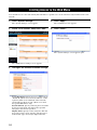
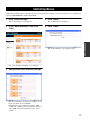
Controlling Noises
Follow the procedure below to configure the noise reduction level according to your environment. You can configure the
settings for MIC/LINE IN1 and IN2 individually.
1 Click "Sound Settings".
The "Sound Settings" screen appears.
2 In the "Noise Reduction" field, click
4 Click "Apply".
The confirmation screen appears.
5 Click "Close".
"Edit".
CONFIGURATIONS
The "Sound Settings" screen appears again.
The "Noise Reduction Settings" screen appears.
3 Configure the noise reduction settings.
Use: Select whether to use the noise reduction. To use
the noise reduction, select "Enable".
Level: Select a noise reduction level from "6dB",
"12dB" and "17dB". If your environment is noiseless,
select "6dB". If your environment is noisy, select
"17dB".
27
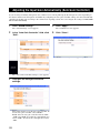
Adjusting the Input Gain Automatically (Auto Gain Controller)
If you are using a boundary microphone, the volume level of sounds picked up by the microphone varies depending on
the distance between the microphone and talker. By configuring the auto gain controller settings, this unit automatically
optimizes the pickup gain according to the volume level of pickup sounds. You can configure the settings for MIC/LINE
IN1 and IN2 individually.
1 Click "Sound Settings".
The "Sound Settings" screen appears.
2 In the "Auto Gain Controller" field, click
4 Click "Apply".
The confirmation screen appears.
5 Click "Close".
"Edit".
The "Sound Settings" screen appears again.
The "Auto Gain Controller Settings" screen appears.
3 Configure the auto gain controller
settings.
Use: Select whether to use the auto gain controller. To
use the auto gain controller, select "Enable".
Level: Select an auto gain control level from "6dB",
"10dB" and "20dB". To widen the sound pickup area,
select "20dB". To narrow the sound pick area, select
"6dB".
28
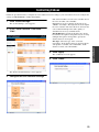
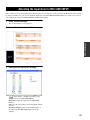
Adjusting the Input Gain for MIC/LINE INPUT
If the volume level of sounds picked up by the microphone is too high, the sounds cannot be handled by this unit and will
be distorted. In this case, you need to adjust the input gain so that the INPUT LEVEL LED does not turn on in red. You
can configure the settings for MIC/LINE IN1 and IN2 individually.
1 Click "Sound Settings".
The "Sound Settings" screen appears.
2 In the "Gain" field, click "Edit".
CONFIGURATIONS
The "Gain Settings" screen appears.
3 Configure the input gain settings.
: Select "MIC" or "LINE" depending on the
device connected to MIC/LINE INPUT.
Slider bar: Adjust the input gain for MIC/LINE
INPUT.
Save: Save the gain settings to this unit's built-in flash
memory.
Hardware Adjust: Adjust to the GAIN settings on
the main unit. The MIC/LINE input level is also
adjusted.
29
Adjusting the Volume Level
Follow the procedure below to adjust the volume levels of
the microphone and speakers connected to this unit.
1 Click "Sound Settings".
The "Sound Settings" screen appears.
2 In the "Level" field, click "Edit".
The "Level Settings" screen appears.
3 Configure the volume level of each
device.
: Select "MIC" or "LINE" depending on the
device connected to CONFERENCE OUT.
Slider bar: Adjust the volume level.
MUTE: Temporarily turn off (mute) the microphone
or speakers. To cancel the mute function, click
"MUTE" again.
Save: Save the volume settings to this unit's built-in
flash memory.
30
Using the Internal Mixer
You can select whether to output audio input through MIC/LINE to LINE OUTPUT. You can configure the settings for
MIC/LINE IN1 and IN2 individually.
1 Click "Sound Settings".
5 Click "Close".
The "Sound Settings" screen appears.
2 In the "Mixer" field, click "Edit".
The "Mixer Settings" screen appears.
The "Sound Settings" screen appears again.
CONFIGURATIONS
3 Configure the internal mixer settings.
Output to LINE OUT: Select whether to output
audio input through MIC/LINE to LINE OUTPUT.
To output audio, select "Enable".
4 Click "Apply".
The confirmation screen appears.
31
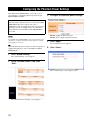
Configuring the Phantom Power Settings
If the DIP switch (PHANTOM) is set to ON, you can
select whether to supply the phantom power thorough
MIC/LUNE IN1 and IN2.
3 Configure the phantom power settings.
Do not turn on the phantom power when a device which
does not require a phantom power is connected to MIC/
LINE INPUT. Incorrect settings may cause a
malfunction of the external devices. For your safety, the
phantom power is not supplied unless it is enabled on
the web menu even if the DIP switch (PHANTOM) is
set to ON.
Note
Enable: Supply the phantom power.
Disable: Not to supply the phantom power.
Use the DIP switch (PHANTOM) to turn on the phantom power
only when a condenser microphone which requires an external
power supply is connected.
4 Click "Apply".
y
While the phantom power is turned on, DC+48V power is
supplied through pins 2 and 3 of the XLR jack (MIC/
LINE INPUT).
5 Click "Close".
The confirmation screen appears.
1 Click "Sound Settings".
The "Sound Settings" screen appears.
2 In the "Phantom Power" field, click
"Edit".
The "Sound Settings" screen appears again.
The "Phantom Power Settings" screen appears.
32
Configuring This Unit's Settings Automatically (Auto Analyzer)
The auto analyzer function automatically sets the echo canceller and feedback suppressor settings best suited for your
environment (types of microphone and speakers, size of conference room, etc.).
1 Click "Sound Settings".
The "Sound Settings" screen appears.
2 In the "Special Function" field, click
"Execute".
CONFIGURATIONS
The "Auto Analyzer" screen appears.
3 Click "Auto Analyzer Start".
For information about the operations during the auto
analyzer process, refer to “Automatic Setup by Auto
Analyzer” (page 15).
33
Turning On/Off the Audio Guidance
Follow the procedure below to turn on/off the audio guidance which notifies you of events during the auto analyzer
process. Also, you can set the volume level of the audio guidance.
1 Click "System Settings".
5 Click "Close".
The "System Settings" screen appears.
2 In the "Audio Guidance" field, click
"Edit".
The "System Settings" screen appears again.
The "Audio Guidance Settings" screen appears.
3 Configure the audio guidance settings.
Guidance: Select whether to use the audio guidance.
To use the audio guidance, select "Enable".
Volume: Select a volume level of the audio guidance.
4 Click "Apply".
The confirmation screen appears.
34
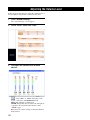
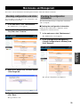
Maintenance and Management
You can use various maintenance and management features of this unit with the web menu.
Checking configurations and status
You can output a report that shows the configurations and
status of this unit as a text file.
1 In the web menu, click "Maintenance".
The "Maintenance" screen appears.
2 In the [Make Report] - [Output Reports to
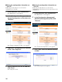
Checking the configuration
information
This unit internally manages configuration information
with a config file.
■Viewing the configuration information
Follow the procedure below to display the current
configurations on the PC monitor.
File] field, click "Execute".
1 In the web menu, click "Maintenance".
The "Maintenance" screen appears.
2 In the [Configuration Management] [Output Configuration to Window] field,
click "Execute".
OPERATIONAL
MANAGEMENT
The "Output Reports to File" screen appears.
3 Right-click “Report File” and then select
"Save Target As".
The current configurations are displayed.
4 Specify where to save the file and then
click "Save".
The report file is saved.
35
■Saving the configuration information on
your PC
■Saving the configuration information on
this unit
Follow the procedure below to save the current
configurations as a text file.
Follow the procedure below to save the current
configurations on this unit. You can save up to three sets of
configurations.
1 In the web menu, click "Maintenance".
The "Maintenance" screen appears.
1 In the web menu, click "Maintenance".
The "Maintenance" screen appears.
2 In the [Configuration Management] [Output Configuration to File] field, click
"Execute".
2 In the [Configuration Management] [Save/Load Configuration] field, click
"Execute".
The "Output Configuration to File" screen appears.
The "Save/Load Configuration" screen appears.
3 Right-click "Configuration File" and then
select "Save Target As".
3 Click "Save" next to the desired memory
number.
4 Specify where to save the file and then
click "Save".
The config file is saved.
36
The comment input screen appears.
4 Enter a comment and then click "Apply".
You can input a comment if necessary. The comment
will be displayed under "Save Time" in the "Save/
Load Configuration" screen.
■Recalling configurations saved on this
unit
1 In the "Save/Load Configuration"
screen, click "Load" next to the desired
memory number.
The confirmation screen appears.
5 Click "Close".
The confirmation screen appears.
2 Click "OK".
OPERATIONAL
MANAGEMENT
The "Maintenance" screen appears again.
The result confirmation screen appears.
3 Click "Close".
This unit restarts.
37
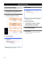
Checking the system logs
This unit records the operation history as system logs
(SYSLOG).
■Configuring the log settings
Follow the procedure below to change the contents of logs
to be output or specify where to save log files.
1 In the web menu, click "Maintenance".
Host Address: Specify where to save log files. Select
"Specify" and then enter a destination IP address.
DEBUG: Select whether to output information about
the internal processing of this unit.
INFO: Select whether to output information about
the system status of this unit.
NOTICE: Select whether to output notifications and
warning information.
Flash-Memory Save Interval: Select an interval to
automatically save logs to this unit's built-in flash
memory.
The "Maintenance" screen appears.
Note
2 In the [SYSLOG Management] field, click
"Edit".
If you turn off this unit before logs are saved to this unit's built-in
flash memory, the unsaved logs will be cleared.
4 Click "Apply".
The confirmation screen appears.
5 Click "Close".
The "Maintenance" screen appears again.
The "SYSLOG Settings" screen appears.
3 Configure the log settings.
38
■Viewing the system logs
Follow the procedure below to display the system logs (up
to 500 lines) on the PC monitor.
1 In the web menu, click "Maintenance".
The "Maintenance" screen appears.
2 In the [SYSLOG Management] - [Output
SYSLOG to Window] field, click
"Execute".
The "Output SYSLOG to File" screen appears.
3 Right-click "SYSLOG File" and then
select "Save Target As".
OPERATIONAL
MANAGEMENT
The system logs are displayed.
■Saving the system logs on your PC
Follow the procedure below to save the current system
logs as a text file.
1 In the web menu, click "Maintenance".
The "Maintenance" screen appears.
2 In the [SYSLOG Management] - [Output
SYSLOG to File] field, click "Execute".
4 Specify where to save the file and then
click "Save".
The SYSLOG file is saved.
■Saving the system logs on this unit
Follow the procedure below to save the current system
logs to this unit's built-in flash memory.
1 In the web menu, click "Maintenance".
The "Maintenance" screen appears.
2 In the [SYSLOG Management] - [Save
SYSLOG] field, click "Execute".
39
2 In the [SYSLOG Management] - [Delete
SYSLOG] field, click "Execute".
The "Save SYSLOG" screen appears.
3 Click "Save".
The "Delete SYSLOG" screen appears.
3 Click "Delete".
The confirmation screen appears.
4 Click "Close".
The confirmation screen appears.
4 Click "Close".
The "Maintenance" screen appears again.
■Deleting the system logs
Follow the procedure below to delete the current system
logs.
1 In the web menu, click "Maintenance".
The "Maintenance" screen appears.
40
The "Maintenance" screen appears again.
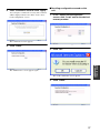
Checking the error history
You can check the history of errors occurred on this unit.
This may bring an early solution to system problems.
■Saving the error history on your PC
Follow the procedure below to save the error history as a
CVS file.
■Viewing the error history
y
You can save the error history which you can view by
carrying out "Viewing the error history".
Follow the procedure below to display the error history
(up to 1500 events) on the PC monitor.
1 In the web menu, click "Error History".
The "Error History" screen appears.
1 In the web menu, click "Error History".
The "Error History" screen appears.
2 In the [Selecting Condition] field, specify
the conditions (period and error level) to
filter the error history to be output and
then click "Apply".
2 In the [Error History Management] [Output Error History to CSV File
(selecting condition is applied)] field,
click "Execute".
Period (YYYY/MM/DD): Specify a period to filter
the error history.
Error Level: Specify an error level to filter the error
history. Select "Level 1" for minor errors (error in
operation, etc.), "Level 2" for temporary errors
(operation error, etc.) and "Level 3" for permanent
errors (misconfiguration, malfunction, etc.).
3 Right-click "Error History CSV File" and
then select "Save Target As".
3 In the [History] field, check the error list.
4 Specify where to save the file and then
click "Save".
The CSV file is saved.
41
OPERATIONAL
MANAGEMENT
The "Output Error History to CSV File" screen
appears.
■Saving the error history on this unit
Follow the procedure below to save the error history to
this unit's built-in flash memory.
4 Click "Close".
1 In the web menu, click "Maintenance".
The "Maintenance" screen appears.
2 In the [Error History Management] [Save Error History] field, click
"Execute".
The "Maintenance" screen appears again.
■Saving the error history automatically
You can set the interval to automatically save the error
history to this unit's built-in flash memory.
Note
The error history that has not been saved to the flash memory will
be cleared if this unit is turned off.
1 In the web menu, click "Maintenance".
The "Maintenance" screen appears.
2 In the [Error History Management] The "Save Error History" screen appears.
[Flash-Memory Save Interval] field, click
"Edit".
3 Click "Save".
The confirmation screen appears.
The "Error History Settings" screen appears.
42
3 Select an interval to automatically save
the error history and then click "Apply".
The confirmation screen appears.
4 Click "Close".
The "Delete Error History" screen appears.
3 Click "Delete".
OPERATIONAL
MANAGEMENT
The "Maintenance" screen appears again.
■Deleting the error history
Follow the procedure below to delete the current error
history.
1 In the web menu, click "Maintenance".
The confirmation screen appears.
4 Click "Close".
The "Maintenance" screen appears.
2 In the [Error History Management] [Delete Error History] field, click
"Execute".
The "Maintenance" screen appears again.
43
Special Functions
Protecting the settings
4 Click "Close".
You can protect the settings of this unit.
1 In the web menu, click "Maintenance".
The "Maintenance" screen appears.
2 In the [Special Functions] - [Config
Protection] field, click "Execute".
The protection is enabled and the "Maintenance"
screen appears again.
To disable the protection
1 In the [Special Functions] - [Config
Protection] field, click "Execute".
The "Config Protection" screen appears.
2 Click "Protect Release".
The confirmation screen appears.
3 Click "Close".
The protection is disabled and the "Maintenance"
screen appears again.
The "Config Protection" screen appears.
3 Click "Protect Set".
The confirmation screen appears.
44
Restarting this unit
4 Click "Close".
You can forcibly quit all the operations in process and
restart this unit.
1 In the web menu, click "Maintenance".
The "Maintenance" screen appears.
2 In the [Special Functions] - [Restart]
field, click "Execute".
The unit restarts.
OPERATIONAL
MANAGEMENT
The "Restart" screen appears.
3 Click "Apply".
The confirmation screen appears.
45
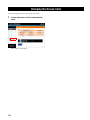
Changing the Screen Color
You can change the screen color of the web menu.
1 In the web menu, click a desired color
chip.
The screen color changes.
46
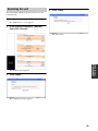
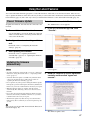
Using the Latest Features
You can download the firmware (program to control the functions of this unit) to use the latest features. There are two
ways to update the firmware of this unit: One way is that you connect this unit to the Internet and automatically install the
latest firmware (page 47). The other way is that you download the firmware to a PC and install it manually (page 49).
Flow of Firmware Update
To update the firmware, this unit must be connected to the
network.
1 In the web menu, click "Maintenance".
The "Maintenance" screen appears.
2 In the [HTTP Revision-up] field, click
1 Connect this unit to the network.
"Execute".
Use a LAN cable to connect the LAN port of this unit
and the network. Before connecting a LAN cable, be
sure to turn off this unit.
2 Configure the network settings of this
unit.
For details, refer to “Configuring the Network
Settings” (page 21).
3 Start updating the firmware.
For details, refer to “Updating the firmware
automatically” (page 47) or “Updating the firmware
manually” (page 49).
Notes
• To update the firmware automatically, you need to configure the
DNS server setting. For details, refer to “3. Specifying a DNS
server” (page 23).
• Automatic firmware update is available only when this unit is
connected to the Internet. If not, follow the procedure in
“Updating the firmware manually” (page 49).
The "Confirmation of software licensing agreement"
screen appears.
3 Read the contents of license agreement
carefully and then click "agree and
execute".
• Do not perform any other operation during the firmware update.
If the update operation is interrupted, this unit may malfunction.
In that case you need to return this unit to the factory for repairs.
• When the firmware update is complete, this unit restarts
automatically. The calls being connected are disconnected at
this time.
• Do not disconnect the LAN cable during the firmware update.
Otherwise, this unit may malfunction. In that case you need to
return this unit to the factory for repairs.
• The firmware update may delete the logs saved in this unit's
flash memory. We recommend you save the important log data
as a file.
y
You can also specify the URL from which the firmware is
downloaded (page 48).
The firmware update starts.
47
OPERATIONAL
MANAGEMENT
Updating the firmware
automatically
The firmware update process takes a few
minutes
During the firmware update process, the LEDs turn on in
rotation. Never turn off this unit while the LEDs are turned
on.
3 Configure the automatic firmware
update settings.
When the firmware update is complete
This unit restarts automatically. Confirm that the version
number has been updated in the "Software Revision" field
in the "Top Page" screen of the web menu.
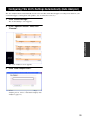
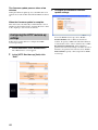
Configuring the HTTP revision-up
settings
Follow the procedure below to configure the HTTP
revision-up settings.
1 In the web menu, click "Maintenance".
The "Maintenance" screen appears.
2 In the [HTTP Revision-up] field, click
"Edit".
The "HTTP Revision Up Settings" screen appears.
48
Service: Select whether to use the HTTP revision-up.
To use the HTTP revision-up, select "Enable".
Download URL: Select a firmware download
website. To specify a URL from which the firmware
is downloaded, select "others" and then enter a URL.
Revision Down Permission: Select whether to
permit revision-down (reverting to an older version of
firmware). To permit revision-down, select "Enable".
Timeout Time: Specify a timeout period for HTTP
revision-up.
Updating the firmware manually
If you cannot connect this unit to the Internet directly, you
need to download the latest firmware to your PC, and then
install it using TFTP.
1 Confirm the current version number.
Check the version number displayed in the "Software
Revision" field in the "Top Page" screen of the web
menu.
2 Download the latest firmware to your
PC.
Access the following website and download the latest
firmware.
Projectphone website:
http://www.yamaha.co.jp/english/product/
projectphone/
3 Permit access to the TFTP server.
Select "Maintenance" in the web menu, click "Edit"
in the "TFTP Server" field and then change the
setting in the "TFTP Server Settings" screen.
Follow the procedure below.
■Start "Command Prompt" on a PC which
can access the TFTP server of this unit
When using Windows XP, click the "Start" menu and then
select [All Program] - [Accessories] - [Command
Prompt].
■Enter and run the following command
tftp -i [IP address of this unit] put [file name]
Example:
tftp -i 192.168.100.101 put pjp_ec200.bin
Firmware update starts.
The firmware update process takes a few
minutes
During the firmware update process, the LEDs turn on in
rotation. Never turn off this unit while the LEDs are turned
on.
When the firmware update is complete
This unit restarts automatically. Confirm that the version
number has been updated in the "Software Revision" field
in the "Top Page" screen of the web menu.
OPERATIONAL
MANAGEMENT
Permit all: Allow access from any address.
Permit specific host only: Allow access from the
specified IP address only. Enter an IP address of a PC.
4 Transfer the firmware to this unit.
Notes
• Do not perform any other operation during the firmware update.
If the update operation is interrupted, this unit may malfunction.
In that case you need to return this unit to the factory for repairs.
• When the firmware update is complete, this unit restarts
automatically. The calls being connected are disconnected at
this time.
• Do not disconnect the LAN cable during the firmware update.
Otherwise, this unit may malfunction. In that case you need to
return this unit to the factory for repairs.
49
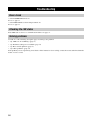
Troubleshooting
Basic check
• Is the POWER LED turned on?
If not, see page 51.
• Is the LINK LED above the LAN port turned on?
If not, see page 51.
Checking the LED status
If the LEDs turn on, there is a communication failure. See page 51.
Solving problems
Consult one of the following description pages according to the problem.
• “Q1: LEDs are off or blinking” (page 51)
• “Q2: Web menu settings are not available” (page 52)
• “Q3: Have an audio problem” (page 53)
• “Q4: Other problems” (page 54)
If the problem you are experiencing is not listed or if the instruction does not help, contact the nearest authorized Yamaha
dealer or service center.
50
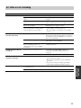
Q1: LEDs are off or blinking
Problem
No LEDs turn on.
The LINK LED above the LAN
port does not turn on.
The INPUT LEVEL LEDs do
not turn on.
The PHANTOM/VOLUME/DIP
SW LEDs are blinking.
Cause
Remedy
This unit is not turned on.
Set the power switch to on.
The power cable is not connected to the AC
outlet.
Check that the power cable is connected to the AC outlet
properly.
The main or branch circuit breaker is shut
off.
• If the circuit breaker is tripped to off, set it to on.
There is a power failure.
Wait until the power supply is restored.
Power is not supplied to the AC outlet.
(Carry out the test by connecting another
electrical appliance to the AC outlet.)
• If another appliance can neither be turned on, have the
power outlet or power wiring serviced.
The PC or hub is turned off.
Check that this unit and the devices connected to this
unit are turned on. Even when the device is connected to
the LAN port properly, the LINK LED does not turn on
if the device is turned off.
The connections are improper.
Disconnect the connections between this unit, PC and
hub and then connect them firmly.
The LAN (network) card installed on your
PC is not working properly, or its
communication mode is not compatible
with this unit.
Check the installation of the LAN (network card) and
communication mode.
The phantom power setting is incorrect.
Set the DIP switch (PHANTOM) to ON when a
microphone which requires a phantom power is
connected.
The input gain for MIC/LINE IN is too low.
Increase the input gain.
The settings are not reflected to this unit.
• If this unit is in the auto analyzer process, wait until
the auto analyzer is complete.
• If the circuit breaker is on, set it to off then on again.
• If another appliance can be turned on, have this unit
serviced.
• If the settings of this unit are protected, disable the
protection.
• If you want to change the settings using the DIP
switch, make the DIP switch settings prioritized.
All LEDs turn on.
Wait for about three seconds.
This unit is broken down.
Have this unit serviced.
ADDITIONAL
INFORMATION
Immediately after the power has been turned
on (normal behavior).
51
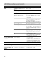
Q2: Web menu settings are not available
Problem
Cannot access the web
menu.
Cause
Remedy
This unit does not recognize the PC. (The
LINK LED above the LAN port does not
turn on.)
Refer to “The LINK LED above the LAN port does not
turn on.” (page 51)
The PC's network settings are incorrect
(other PCs and printers on the LAN are not
functioning).
• Reconfigure the LAN board or LAN card settings and
then reboot the PC.
This unit is malfunctioning.
Initialize this unit and then reconfigure the settings.
(page 56)
The network settings of this unit are
incorrect.
• If connecting to a PC through a LAN port, set the IP
address of the LAN port.
• Reset the IP address of the PC.
• Configure the default gateway setting according to
your environment.
Access to the web menu is not authorized.
If the IP address access limitation feature is enabled, the
following message will be displayed when you try to
connect from an unauthorized host:
"Error503 This server is available to members only. I'm
sorry, your host is not member."
The specified URL is invalid.
When using this unit for the first time or after initializing
this unit, access "http://192.168.100.101/."
The web browser is not configured to
connect via LAN.
If you are using Windows Internet Explorer 6: the
connection settings are found in the "Connection" tab
under "Internet Options". If the connection method is set
to dial-up, the browser will not be able to access the web
menu. Change the connection setting to "Never dial a
connection".
The Web browser is using a proxy server.
If you are using Windows Internet Explorer 6: Select
[Tools] - [Internet Options] - [Connection] tab - [LAN
Settings] and then uncheck the "Use a proxy server for
your LAN" box.
You cannot remember the IP address of this
unit.
• Press INITIALIZE when this unit is turned on to reset
the network settings to the default.
• Turn on this unit while holding down INITIALIZE to
reset all settings of this unit to the default.
• The password is case sensitive. Make sure that the case
is correct for every letter.
Cannot access the web menu
is inaccessible after entering
a password.
The password is incorrect. (The error
message is displayed).
Cannot change the settings
from the web menu.
The web menu settings are not prioritized.
Set the DIP switch (DIP SW) to ETHER. (page 10)
Cannot save a password in
the web browser for logging
in to the web menu.
The user box is blank on the "Network
Password" screen.
Some web browsers require entering your user name to
save the password. In this case, enter "pjp-ec200" as a
username.
A login prompt appears even
though a password has not
been set.
A login prompt will appear even if no
password has been set (normal behavior).
Enter "pjp-ec200" as a username while leaving the
password blank and then click "OK".
52
• A problem may arise if the browser stores incorrect
authentication information (user name and password)
and automatically uses it to access this unit. In this
case, clear the authentication information currently
stored and enter the correct user name and password.
Q3: Have an audio problem
Problem
The audio from the PC or
videoconference system
cannot be heard or is
distorted.
The audio output to the PC or
videoconference system
cannot be heard or is
distorted.
This unit generates echoes.
Cause
Remedy
The input level setting is incorrect.
Configure the input level setting on the device connected
to this unit.
The input level of CONFERENCE IN is too
low.
Increase the input level. (page 30)
The output level setting is incorrect.
Switch between MIC level and LINE level depending on
the device connected to MIC/LINE INPUT. (pages 10
and 29)
The output level of CONFERENCE OUT is
too low.
Increase the output level. (page 30)
The echo canceller setting is improper.
Run the auto analyzer.
The echo reduction level is too low.
Adjust the echo reduction level in the web menu.
The volume level of the speakers is too high.
• Turn the speaker volume level down.
• Keep the speakers away from the microphone.
This unit generates acoustic
feedback noises.
The input gain for MIC/LINE IN is
extremely high.
Adjust the input gain so that the INPUT LEVEL LED
does not turn on in red. (pages 9 and 29)
This unit is used in the environment where
acoustic feedback is frequently generated.
• Change the positions of the microphone and speakers.
The feedback suppressor level is too low.
• Adjust the echo reduction level in the web menu.
• Run the auto analyzer.
• Configure the "Band width" setting in the web menu.
(page 26)
The input gain for MIC/LINE IN is
extremely high.
Adjust the input gain so that the INPUT LEVEL LED
does not turn on in red. (pages 9 and 29)
ADDITIONAL
INFORMATION
53
Q4: Other problems
Problem
Cannot synchronize the
clock with an NTP server.
Cause
The IP address or domain name of the NTP
sever is incorrect.
Remedy
• Check that the settings match the NTP server
information.
• Ping the NTP server to confirm that it is functioning.
A route to connect with the specified NTP
server has not been set.
Check the Internet service provider settings or route
settings.
An incorrect time is not
displayed.
The time zone setting is incorrect.
Set the time zone according to your area.
The clock setting cannot be
saved.
The built-in battery (for clock memory) is
run out.
• Supply the power to this unit for about five hours to
change the built-in battery.
• Have this unit serviced.
The phantom power is not
supplied.
The phantom power setting is incorrect.
Enable the phantom power with the DIP switch or web
menu (depending on the DIP switch setting). (pages 10
and 32)
Cannot output your own
voices from your speakers.
The internal mixer is disabled.
Enable the internal mixer. (pages 10 and 31)
The audio cannot be output.
The mute function is turned on in the web
menu.
Turn off the mute function. (page 30)
Firmware update fails.
Timeout happens because the timeout
period for HTTP revision-up is too short.
Increase the timeout period in the web menu. (page 48)
The download URL setting is incorrect.
Configure the download URL setting correctly.
Cannot update the firmware
by TFTP.
54
The DNS server setting is incorrect.
Configure the address of the DNS server correctly.
The access permission setting is incorrect.
Configure the access permission setting correctly.
(page 49)
List of Error Messages
Patterns of front LEDs
MIC/LINE
IN1
Error type
IN2
CONFERENCE
PHANTOM
GAIN KNOB
DIP SW
Blink green/red
Blink green,
On red
Blink green
Off
Blink green
Blink green
Detects a problem during
system startup.
Blink green/red
Blink green,
On red
Blink green,
On red
Off
Blink green
Blink green
Firmware update failed.
Blink green/red
Blink green/red
Off
Blink green
Blink green
Detects a material error.
Blink green
Blink green
Blink green,
On red
On red
Blink green
Blink green
MIC/LINE IN1 gain is too
small or no device is
connected.
Blink green
Blink green,
On red
Blink green
On red
Blink green
Blink green
MIC/LINE IN1 gain is too
high.
Blink green
Blink green,
On red
Blink green,
On red
Blink green
Blink green
Input to MIC/LINE IN1 is
noisy or test tone is clipped.
Blink green,
On red
Blink green
Blink green
On red
Blink green
Blink green
Delay between LINE
OUTPUT and MIC/LINE
IN1.
Blink green,
On red
Blink green,
On red
Blink green
On red
Blink green
Blink green
Too much acoustic
feedback at MIC/LINE IN1.
Adjust the microphone
orientation, gain or speaker
volume.
Blink green,
On red
Blink green,
On red
Blink green,
On red
On red
Blink green
Blink green
Cannot run the auto
analyzer because the
settings are being
configured.
Blink green
Blink green
Blink green,
On red
Blink red
Blink green
Blink green
MIC/LINE IN2 gain is too
small or no device is
connected.
Blink green
Blink green,
On red
Blink green
Blink red
Blink green
Blink green
MIC/LINE IN2 gain is too
high.
Blink green
Blink green,
On red
Blink green,
On red
Blink red
Blink green
Blink green
Input to MIC/LINE IN2 is
noisy or test tone is clipped.
Blink green,
On red
Blink green
Blink green
Blink red
Blink green
Blink green
Delay between LINE
OUTPUT and MIC/LINE
IN2.
Blink green,
On red
Blink green,
On red
Blink green
Blink red
Blink green
Blink green
Too much acoustic
feedback at MIC/LINE IN2.
Adjust the microphone
orientation, gain or speaker
volume.
Blink green,
On red
Blink green,
On red
Blink green,
Blink red
Blink green
Blink green
The auto analyzer process
quits because the settings
are changed.
On red
On red
55
ADDITIONAL
INFORMATION
Blink green/red
Resetting the Settings of This Unit
Resetting all settings
You can reset the web menu settings and settings internally saved in this unit to the default.
Notes
Please note the followings when you reset the settings of this unit.
• This operation will disconnect all the calls being connected.
• This operation will restore the factory default values (if available).
• This operation will overwrite data stored in the nonvolatile memory.
• You cannot undo the reset operation.
■Initializing using the web menu
■Initializing using the button on the main
unit
1 In the web menu, click "Maintenance"
and then click "Execute" in the [Special
Functions] - [Recover Initial Settings]
field.
1 Turn off this unit.
You do not need to disconnect cables.
2 While holding down INITIALIZE, turn on
2 Click "Apply".
The confirmation screen appears.
3 Click "Close".
The settings of this unit are reset to the default. Since
the configurations you have made are all cleared, you
need to reconfigure this unit.
this unit.
Since the button is located inside the small hole, use a
ballpoint pen or similar object to press the button.
The front LEDs blink several times.
3 3 Release INITIALIZE.
The settings of this unit are reset to the default. Since
the configurations you have made are all cleared, you
need to reconfigure this unit.
Resetting the network settings
In case that you cannot access the web menu (setting an incorrect IP address, etc.), follow the procedure below to reset
the network settings of this unit.
Note
This operation will reset "LAN Port Settings", "Default Gateway Settings" and "DNS Server Settings".
1 Turn on this unit.
2 After this unit is started, press
INITIALIZE.
Since the button is located inside the small hole, use a
ballpoint pen or similar object to press the button.
The front LEDs blink several times.
56
3 Release INITIALIZE.
The network settings (IP address, etc) of this unit are
reset to the default.
Support Information
In case you are in need of support, visit the following website or contact the nearest authorized Yamaha dealer or service
center.
■Checking log information and setting configurations
A Yamaha representative may ask for log (SYSLOG) or configuration (config) information in order to understand the
situation. The problem may be easier to fix if you provide log and configuration information along with a description of
your problem.
For details about how to view the log and configuration information, refer to “Maintenance and Management” (page 35).
■Projectphone website
Please visit the following website for the latest or detailed information.
http://www.yamaha.co.jp/english/product/projectphone/
ADDITIONAL
INFORMATION
57
Specifications
General specifications
Dimensions (W x H x D):
Noise reduction:
270 mm x 42.6 mm x 180 mm
(10-5/8" x 1-3/4" x 7-1/8")
17 dB maximum
Weight:
LINE OUTPUT (L/R): Stereo RCA pin-jacks
CONFERENCE (IN/OUT): Stereo mini jacks
MIC/LINE INPUT: XLR/PHONE combo jacks
2ch (48-V phantom power supply supported)
850 g (1.9 lbs)
Power supply:
AC 100 to 240 V (50/60 Hz)
Power consumption:
6 W maximum
Radio interference standard:
VCCI Class A, KN22, KN24
Operating environment:
Ambient temperature: 0 to 40°C (32 to 104 °F)
Ambient humidity: 15% to 80% (no condensation)
Audio range:
100 to 20,000 Hz
Arrival time of the direct sound:
120 ms maximum
Echo cancelling time:
400 ms maximum
Echo canceling quantity:
60 dB maximum
58
Interfaces:
Supplied accessories:
[Japan model]
AC adapter x 1, Power cable x 1, CD-ROM x 1,
Installation/Setup Manual x 1, Warranty x 1
[Korea model]
AC adapter x 1, Power cable x 1, CD-ROM x 1,
Installation/Setup Manual x 2
[Other models]
AC adapter x 1, Power cable x 1, CD-ROM x 1,
Installation/Setup Manual x 1
Input specifications
Input level
Terminal
Specification
XLR, balanced type IN1&2 (MIC)
Rated input level
Maximum
input level
-60 dBµ to -20 dBµ
-6 dBµ
Input
impedance
3 kΩ
50 to 600 Ω
MIC/LINE INPUT
(IN1/IN2)
XLR, balanced type IN1&2 (LINE)
-30 dBµ to +10 dBµ
+20 dBµ
PHONE, unbalance type IN1&2 (MIC)
-60 dBµ to -20 dBµ
-6 dBµ
PHONE, unbalance type IN 1&2 (LINE)
-30 dBµ to +10 dBµ
+20 dBµ
-7.8 dBµ
0 dBµ
Mics/Lines
2.4 kΩ
CONFERENCE IN
Mini jack, unbalance type
15 kΩ
The XLR jacks are compatible with phantom power (+48 V)
0 dBµ = 0.775 Vrms, 0dBV = 1 Vrms
Output specifications
Output level
Terminal
MAIN OUT
Specification
Output
impedance
Rated output level
Maximum
output level
RCA pin jack, unbalance type
-10 dBV
-3 dBV
600 Ω
Mini jack, unbalance type
CONF.OUT (LINE)
-10 dBV
-3 dBV
600 Ω
Mini jack, unbalance type
CONF.OUT (MIC)
-30 dBV
-23 dBV
600 Ω
CONFERENCE OUT
0 dBµ = 0.775 Vrms, 0dBV = 1 Vrms
ADDITIONAL
INFORMATION
59
(September 2009, 1st edition)