1
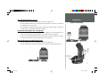
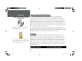
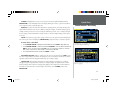
™
StreetPilot III
portable GPS with
auto-routing and voice
d
Rea
This !
t
Firs
real qs.indd
1
quick start
guide
3/16/01, 5:54 PM
Quick Start
Before using your StreetPilot III, check to see that your package includes the following items. If you
are missing any parts, please contact your GARMIN dealer immediately.
Packing List
Standard Package:
• StreetPilot III with Detachable Antenna
• Owner’s Manual
• Quick Start Guide
• Dash Mount Kit
• External Speaker System with 12-volt Adapter
• MapSource City Navigator CD-ROM
Help us better support you by completing your on-line registration today! Why should you register your StreetPilot III?
• USB Programmer
• USB Programmer User’s Manual
• MapSource User’s Manual
• Notification of Product Updates
• Notification of New Products
• Lost or Stolen unit tracking
• 32MB Blank Data Card
• PC Cable
Visit our website (www.garmin.com) and look for the
Product Registration link on the home page. If you have any
questions or comments regarding the use of the StreetPilot III
you can visit our web site or contact our Customer Service
Department M-F, 8:00-5:00 Central Time (except holidays)
at 1-800-800-1020.
• Single DCA Unlock Code Certificate
Optional accessories for the StreetPilot III are listed in the Owner’s Manual, starting on page 48.
2
real qs.indd
2
3/16/01, 5:54 PM
Thank you for purchasing the GARMIN StreetPilot III—the result of our continuing effort to
provide quality, user-friendly automotive navigation systems to suit all your needs. This Quick Start
Guide is designed to introduce the basic functions of the unit. Please take a few moments now to
review the features of your StreetPilot III, as illustrated below. After reading through this guide, if
you have additional questions regarding a particular feature, more information can be found in the
Owner’s Manual.
Power/Data Connector
Detachable Antenna
(Back Side) Connections for
Power, Ground, Serial Data
In and Serial Data Out.
Rotate upright for best
satellite reception.
Quick Start
Unit Features
Power/Backlight Key
Press and hold to turn
on/off. Press momentarily
to adjust screen backlight
and contrast.
16-Color LCD Display
On-screen information is
referred to as a “page”.
Press PAGE key to select
a different screen.
Rocker Keypad
Moves the cursor, pans
the Map Page and
enters data.
Battery Door
Cartridge Door
(Back Side) To open, turn metal D-ring
counterclockwise 1/4 turn and pull
battery door away from unit.
(Bottom) Insert programmed card
for increased map detail and information lookup capability.
3
real qs.indd
3
3/16/01, 5:54 PM
Quick Start
Installing The Batteries
The StreetPilot III uses six (6) AA batteries, which are installed at the back of the unit. Alkaline,
rechargeable, Lithium, or Ni-Cad batteries can be used. Battery life will vary due to a variety of factors,
including surrounding temperature and the use of backlighting. You may find that Lithium batteries
provide longer life in colder conditions. Saved information will not be lost when you replace the
batteries.
I
• Observe correct polarity when installing batteries.
• Replace all batteries at the same time.
• Do NOT mix new and used batteries.
• Do NOT mix Alkaline batteries with Lithium or Ni-Cad
rechargeable batteries.
Immediately after you install new batteries, turn the unit on
to ensure that the unit’s battery strength indicator displays a
fully-charged battery condition.
If the unit does not turn on or the battery level indicator
displays a partially charged battery condition, recheck for
proper battery installation. If, after checking installation,
the battery level indicator continues to indicate a partially
charged condition, the newly installed batteries may be
depleted from long-term storage. Replace with fresh batteries.
WARNING: It is very important to install ALL batteries with the proper polarity, positive (+)
or negative (-), orientation as indicated in the unit’s battery compartment. Batteries can
leak and cause personal injury and property damage if you install them incorrectly.
A power symbol (electrical plug) appears at the bottom of the Main Menu and in the upper left
hand corner of the Trip Information Page (see page 13) when the unit is running on external power.
When the unit is running on AA batteries, instead of the power symbol a green battery strength bar
indicator appears. The bar shortens as the unit uses battery power. To conserve battery life you can
switch to Battery Saver mode (see Owner’s Manual page 41) or you can use the Vehicle Power Cable.
When the battery power falls below a certain level, the bar indicator turns red. You should replace
the batteries when this occurs. In addition, a ‘battery voltage is low’ message appears at the bottom
of the page.
To install the batteries:
1. Lift up the metal D-ring at the back of the unit and turn it ¼ turn counterclockwise to open the
compartment door.
2. Install the batteries (as shown at left and as marked in the battery compartment).
3. Turn the D-ring ¼ turn clockwise to lock the door in place.
4
real qs.indd
4
3/16/01, 5:54 PM
The StreetPilot III is portable, allowing you to easily carry the unit from vehicle to vehicle or take
it with you once you reach your destination. A Dash Mount kit consisting of a mounting bracket,
mounting base, required hardware and adhesive pads is included with the StreetPilot III. Installation
of the mounting bracket should be performed with consideration for the following safety diagram
and warnings:
Do Not Place Unsecured
on the Vehicle Dash
Do Not Mount Where Driver’s
Field of Vision is Blocked
Do Not Mount Over
Airbag Panels
Do Not Mount in Front
of an Airbag Field of
Deployment
Installing the Mounting Base
1. Select a suitable location for installation that allows routing of an external power cord and/or
antenna cable (if needed) to the GPS unit. If you are NOT using a remote antenna, be certain to
select a location where the GPS unit’s antenna has a relatively unobstructed view of the sky.
2. To secure the mounting base to the dash of the vehicle you may choose either the permanent (hole
in disk) or repositionable adhesive options (no hole in disk). Carefully clean the area where the base
is to be placed using an alcohol dampened cloth. Wipe the area dry with a clean, dry cloth. Remove
one side of the protective backing from the adhesive, and place on the bottom of the base. Remove
the remaining backing from adhesive and position the base on the cleaned area. Be certain the
locking lever on the base faces forward for easy access.
Mounting Base
Mounting Surface
Adhesive Disk
(permanent shown)
Secure Mounting Base with Disk Adhesive
real qs.indd
5
Quick Start
Vehicle Installation
WARNING: For use in vehicles, it is the sole responsibility
of the owner/operator to place and secure the GPS unit so
that is will not interfere with the vehicle operating controls
and safety devices, obstruct the driver’s view of driving
conditions, or cause damage or personal injury in the event
of an accident. Do not place this mounting bracket over
airbag panels or in the field of airbag deployment. Airbags
expand with a rapid fire force that can propel objects in
their path towards the vehicle driver or passengers causing
possible injury. Refer to airbag safety precautions contained
in the vehicle owner’s manual. Do not place this mounting
bracket where the driver or passengers are likely to impact
it in an accident or collision. The mounting hardware
provided by GARMIN is not warranted against collision
damage or the consequences thereof.
NOTE: Allow the permanent adhesive to set 24 hours
before using the dash mount. If permanent adhesive is later
removed, use rubbing alcohol to clean any adhesive residue.
Repositionable adhesive should only be used on clean, dustfree surfaces.
5
3/16/01, 5:54 PM
Quick Start
Installing the GPS Unit into the Mounting Bracket
Vehicle Installation
Locking
Knob
Top Tab
1. Locate the tabs on the base/top of the mounting bracket (see figure to the left) and the corresponding notches on the bottom/top of the GPS unit’s case.
2. Align the bottom notches on the GPS unit with the corresponding two tabs on the mounting
bracket base and push the top of the GPS unit back into the bracket until the top notch and tab
snap in place.
3. Secure the GPS unit in the bracket by tightening the locking knob on the top of the mounting
bracket.
Bottom Tabs
Attaching the External Speaker System with 12VDC Adapter to the GPS
1. Locate the power connector on the rear of the StreetPilot III (behind the rubber weather cap). The
connector is “keyed” with a notch located between two of the four pins.
Mounting Bracket
Locking
Knob
Power
Connector
2. Mate the round, 4-pin power plug on the External Speaker System with 12VDC Adapter to this
connector by aligning the notches and pushing the plug into the connector until fully seated. Insert
the 2.5mm speaker plug into the speaker jack located below the antenna (see figure to the left).
Press the speaker cable into the two cable holders on the back of the mounting bracket.
The 2.5mm mini-jack may be used with the External Speaker System or with your own speaker/
headphone (unpowered and rated at 8 ohms). The speaker which is built into the External Speaker
System with 12VDC Adapter will work without the cable being plugged into the vehicle’s power
source.
3. Plug the cigarette lighter portion of the External Speaker System with 12VDC Adapter into an
available cigarette lighter receptacle in your vehicle. Use care when routing the adapter cable being
certain that it does not interfere with vehicle operation in any way.
Speaker Plug
6
real qs.indd
Speaker Cable
Holders
6
3/16/01, 5:54 PM
Quick Start
Attaching Mounting Bracket to Base
1. Slide the locking lever, on the mounting base, to the left (unlocked position).
2. Attach the bracket assembly to the mounting base by sliding the disk on the bottom of the bracket
into the base until it clicks into place.
Vehicle Installation
3. Rotate the bracket assembly left or right until the desired angle is achieved. Slide the locking lever to
the right (lock) to secure the bracket assembly to the base.
Adjusting the Mounting Bracket’s Viewing Angle
1. Tilt the GPS unit forwards or backwards by pressing and holding down on the adjustment button on
the back side of the bracket assembly. Adjust the unit as desired and release the button.
2. Rotate the entire bracket assembly by sliding the locking lever to the left (unlocked position). Adjust
the angle as desired and move the lever back (right) to the locked position.
Unlock to Adjust
Left/Right
Removing the Bracket Assembly from the Base
1. Slide the locking lever, on the mounting base, to the left (unlocked position).
2. Press the release tab downward and slide the bracket assembly to the right (see figure below).
Press Down to
Adjust Tilt
(Unlocked) Press
Down to Release
7
real qs.indd
7
3/16/01, 5:55 PM
Quick Start
MapSource City Navigator CD-ROM Overview
Datacard Installation & Using
MapSource
The MapSource City Navigator CD is designed specifically
for the StreetPilot III and contains detailed street maps for
major North American cities.
A CD-ROM containing all U.S. and Canadian detailed coverage area (DCAs) is included
with your StreetPilot III. The MapSource City Navigator CD is designed specifically for the
StreetPilot III and contains detailed street maps for major cities. This mapping software allows for
automatic routing and the map data also contains turn restrictions and other routing information. By
simply entering an address, intersection or pointing at the map, the StreetPilot III will automatically
plan a route and provide turn-by-turn directions to that location. You can also look up services or
points of interest and view the address, phone number and map location. Be aware that not all areas are
covered in detail by the City Navigator CD. But to get detailed, street-level routing for major cities, you
need to download maps from the City Navigator CD.
The StreetPilot III will also work with MapSource Roads & Recreation, WorldMap, Topo, and
MetroGuide CDs but, with these products, will not provide detailed automatic routing. If you’re using
StreetPilot III without downloaded maps from the City Navigator CD, you’ll still have automatic routing
capabilities along major streets and highways contained in the built-in “basemap”.
Unlock Codes
You’ll need an uplock code (provided on GARMIN web site
or by phone) to download a detailed coverage area from the
City Navigator CD. Unlock codes are a cost effective way to
distribute all available areas on a single CD.
Record your 25-digit Unlock Code here.
8
real qs.indd
The data on the City Navigator CD is protected by unlock codes. Before you can download
maps from a detailed coverage area, you’ll need to “unlock” that region. Additional instructions for
completing these steps are printed on the MapSource Unlock Certificate (provided with the City
Navigator CD). The Certificate directs you to the GARMIN Web site, where you’ll enter your personal
information, the Unit ID number from your StreetPilot III (see Owner’s Manual page 39), and the
code contained on the certificate. From the web site, you’ll also select a coverage area and see what
cities are included. After you’ve completed the information, the website will provide your official 25
digit unlock code. Now you’re ready to install the City Navigator CD-ROM and start downloading
maps from your PC.
8
3/16/01, 5:55 PM
You received one Metro Area DCA unlock code through web (or phone) registration with the
purchase of your StreetPilot III. So what if you plan to use your StreetPilot III when you’re traveling in
a major city that’s outside the detailed coverage area that you have access to? Just purchase an unlock
code for another DCA, or for the entire U.S. and Canada. You can purchase additional unlock codes
from the GARMIN Web site. Then, using the same City Navigator CD that came with your unit, you’ll
have access to more coverage areas. Keep in mind you will always have good map information from
your StreetPilot III’s built-in basemap without using the City Navigator detail.
Transferring City Navigator CD Data to a Data Card (USB Programmer)
Included with your purchase of the StreetPilot III is a Universal Serial Bus (USB) Data Card
Programmer, which allows you to quickly download maps from your PC to a 32-megabyte data card
that is also included with the StreetPilot III. Follow the directions in the USB Data Card Programmer
User’s Manual to install the software, then connect the programmer to your PC’s USB port. Once you’ve
inserted the City Navigator CD and started the MapSource program on your PC, move the cursor to the
pull-down menu at the top of the screen and select “City Navigator.”
Now, select the detailed coverage areas you want to download. You can continue to add map areas
until the total map size reaches 32-megabytes. Click on the download button at the top of the screen,
and the information quickly downloads to the data card. As you load different map areas, MapSource
will overwrite previously stored data.
Installing The Data Card
When you’re finished downloading, remove the Data Card from the USB Programmer and insert it
into the slot-with the label facing toward the front of the StreetPilot III. Make sure the connector end of
the cartridge is inserted into the slot, NOT the handle end. When properly inserted, the cartridge will
protrude slightly from the slot (not flush).
I
real qs.indd
Quick Start
Datacard Installation & Using
MapSource
The USB Programmer will allow you to download City
Navigator Maps very rapidly using your PC. Refer to the
USB Programmer Owner’s Manual for additional instructions.
NOTE: Older model PC’s may not have a USB port or
operating system support for a USB connection. In such
instances, you can program the Data Card directly through
the StreetPilot III. Connect the StreetPilot III to your PC
using the supplied PC Cable. Insert the Data Card into
the SteetPilot III. Then, run the MapSource program (see
MapSource Owners Manual) to transfer map data.
Using this method to program your Data Card is MUCH
slower than a USB connection. Map data that transfers in
minutes using a USB programmer can take 1/2 hour or
longer when programmed through the StreetPilot III.
CAUTION: Incorrect data card installation can result in internal damage to your GPS unit!
9
9
3/16/01, 5:55 PM
Quick Start
POWER (Red Bulb Symbol)- Press and hold to turn the StreetPilot III on and off. Press momentarily while
power is on to display the backlight/contrast adjustment window.
Keypad Usage
PAGE- Switches between main pages and returns display from an option window back to a main page.
QUIT- Returns display to a previous page. When entering data, restores the previous value (cancels
data entry).
ENTER/MARK- Confirms a selected menu option. When entering data, it allows you to initiate entry, and
then to accept the selected value(s). Press and hold to capture your present position and save it as a
waypoint. ENTER/MARK can also capture the location of the panning arrow on the Map Page.
ROCKER KEYPAD- Selects menu options and enters data. Also controls movement of the panning cursor
on the Map Page.
Zoom IN and OUT- Adjusts map scale to show a smaller area (more detail) or a larger area (less detail).
FIND- Searches the database for Cities, Interstate Exits, Waypoints, and Recently found places. If an
optional MapSource City Navigator or MetroGuide map data card is installed, it also searches for Points
of Interest, Addresses, or Intersections. Allows the listed items to be viewed on a map or selected as a
destination (Note: MetroGuide will not provide turn-by-turn navigation or voice commands).
MENU- Displays a menu of options for the current page. Press twice to display System Setup options.
ROUTE- Displays a pop-up window of route navigation features.
VOL/SPEAK- Press and hold to adjust the external speaker volume. Pressing VOL/SPEAK will repeat the
most recent voice instructions when navigating and display the Next Turn pop-up window.
10
real qs.indd
10
3/16/01, 5:55 PM
CURSOR- A highlighted area on the screen which can be moved up/down/left/right with the
Quick Start
ROCKER KEYPAD to select individual fields on the display. Moving the cursor to a given location allows
you to begin data entry or scroll through a list.
Screen Features / Data Entry
DEFAULT- A system-selected format, built into the operating software or the unit’s memory, that
will be followed unless the user chooses a different setting. For example, the default setting for speed
readings is ‘miles per hour’ or but can be changed to ‘kilometers per hour’. Once a setting is changed,
the new setting is retained until another change is made or a ‘Restore Original Settings’ menu option
is selected.
FIELD- The location on a page where a group of characters or an option is entered and displayed.
The cursor is placed on a field (using the ROCKER KEYPAD) to begin data entry or selection of options.
To enter data in a data field:
1. Use the ROCKER KEYPAD to highlight the desired data field. Press ENTER to begin data entry.
An example of an on-screen button—the ‘Route to It’
button on the Waypoint Marked Page.
2. Use the ROCKER KEYPAD to enter the desired data. UP/DOWN to select the desired character and
RIGHT to move to the next character field. LEFT allows you to back up to the previous character
field or, when at the left-most character field, to clear the entire data field.
3. Once the desired data has been entered, press ENTER to confirm.
ON-SCREEN BUTTON- Similar to “Field”. Place the cursor on a button and press ENTER to select
the action corresponding to that button. An example of an on-screen button is the ‘Route to It’ button
appearing at the bottom of the Waypoint Marked Page (see example at right).
SCROLL BAR- When viewing a list of items too long to display on a single page, a scroll bar
will appear along the right-hand side of the list (see example at right). The position of the scroll bar
indicates which portion of the list is currently being displayed. The height of the scroll bar indicates
the number of items in the list. To scroll through a list of items, use the UP/DOWN portion of the
ROCKER KEYPAD.
The scroll bar appears on the right side of a list too long
to fit on a single page.
11
real qs.indd
11
3/16/01, 5:55 PM
Quick Start
Turning the StreetPilot III On and Off
Turning On/Off
Adjusting Backlighting,
Contrast and Volume
Press and hold the POWER key to turn the unit on (a power tone will momentarily sound). The
Welcome Page appears briefly, followed by the MapSource Copyright Page. Press ENTER to acknowledge
the copyright, or wait briefly until the Safe Driving Warning Message appears. Once again, press ENTER
to acknowledge the warning or wait until the Warning Page is replaced by the Map Page. When the
Map Page appears, the unit is ready for operation.
When you are ready to turn the unit off, press and hold the POWER key.
IN POINT THREE MILES
TURN RIGHT
When the external speaker is connected, your StreetPilot
III provides audible prompts during route navigation.
These ‘spoken’ prompts include approaching turn notification (direction of turn and distance), off course notification, and arrival at destination.
Spoken messages are also provided for poor GPS coverage and low battery power.
Automatic voice prompting can be turned off via a
system setup option (but can always be triggered by
pressing the VOL/SPEAK key (see page 40).
Adjusting the Backlight, Contrast, and Speaker Volume
The StreetPilot III display and keys can be illuminated for operation at night or in bright sunlight. Backlight intensity and screen contrast are adjustable. When
operating the StreetPilot III at extreme temperatures,
you may find that minor adjustments are needed to
obtain the clearest screen.
To adjust screen backlighting and contrast:
1. Press the red POWER key momentarily. An on-screen window appears allowing you to adjust the
backlight and contrast levels.
2. Use the ROCKER KEYPAD to adjust the backlight and the contrast to the desired level. (Alternatively, backlighting can be cycled between three settings by repeatedly pressing the red POWER key.)
The backlight and contrast window will disappear after a few seconds of inactivity.
To adjust the external speaker volume:
1. Press and hold the VOL/SPEAK key. A slider adjustment window appears.
2. Adjust the speaker volume by using the ROCKER KEYPAD. The loudest setting is eight, the
softest is one. (Alternatively, volume can be cycled between three settings by repeatedly pressing
VOL/SPEAK.)
12
real qs.indd
12
3/16/01, 5:55 PM
Unit Pages at a Glance
Quick Start
There are three main pages on the StreetPilot III: the Map Page, Trip Information Page, and Current
Route Page. Press the PAGE or QUIT key to sequence through these pages.
Main Page Sequence
Appears only when a destination is selected.
Current Route Page
Map Page
Trip Information Page
QUIT
PAGE
Virtual Tour
Let’s use the StreetPilot III’s built-in simulator to select a destination, plan a route, and see how
the unit would operate in actual use. This simulated trip will involve the use of the FIND key to show
you how the StreetPilot III guides you through every turn with audible directions. First, if you haven’t
already done so, take the StreetPilot III outside and let it determine your current location.
The first time you use your new StreetPilot III, it will
need to search for GPS satellites and determine its location. This process may take several minutes.
To determine your current position:
1. Turn the StreetPIlot III on by pressing the red POWER key. Make sure the antenna is pointing upward
and you are located in an area with a clear view of the sky.
2. Press ENTER to acknowledge the power-on pages. The power-on process is complete when the Map
Page appears (see page 12).
3. Observe the message banner at the top of the Map Page. When the message changes from “Acquiring
Satellites” to “Ready for Navigation” your StreetPilot III has determined your current position.
You can now continue the remainder of the Virtual Tour indoors. Find a comfortable chair, sit
back and enjoy the trip!
real qs.indd
13
StreetPilot III is ready to guide you when the “Ready for
Navigation” message appears.
13
3/16/01, 5:55 PM
Quick Start
To use the StreetPilot III indoors or simulate a trip:
Finding a Destination
1. With the StreetPilot III turned on, press the MENU Key.
2. Select ‘Use Indoors’ using the ROCKER KEYPAD and press ENTER.
3. Press ENTER again to acknowledge the “GPS turned off” message banner. The StreetPilot III is now
in a simulated operation mode.
F
Select ‘Use Indoors’ when you want to use simulate
navigation.
NOTE: In normal use you WILL NOT follow the steps above to enable the built-in simulator.
Simply turn the StreetPilot III on, select a destination (see steps below) and drive!
Your StreetPilot III includes a built-in database of cities and interstate highway exits. If you’ve
already programmed the data card using your City Navigator CD, you’ll also have access to a second
database that includes Points of Interest, Address lookup and road Intersections. In this Virtual Tour
we’ll use examples for cities (built-in) and points of interest (data card). Once you’ve read through these
examples feel free to experiment on your own with other categories.
To find a destination location:
1. Press the FIND key. The Find Window appears asking what type of location you are looking for.
2. Use the ROCKER KEYPAD to select the desired location type (in this case, Cities) and press
ENTER.
3. The StreetPilot III will search its internal database and present a list of nearby cities.
Press FIND and select ‘Cities’ to display a list of nearby
cities and select a destination.
4. Use the ROCKER KEYPAD to highlight a nearby city on the list and press ENTER. An information
page will appear showing the city name, size, direction and distance to the city (from present
position) and several buttons at the bottom of the page.
F
NOTE: You can find cities by name or from the nearest list. We’ll use the nearest list in this
demonstration, but experiment on your own later (see Owners Manual page 27).
14
real qs.indd
14
3/16/01, 5:55 PM
5. To select this city as a destination, use the ROCKER KEYPAD to highlight “Route To It” and press
ENTER. (Otherwise, press QUIT to return to the nearest city list and repeat step #4.)
6. A pop-up window will appear for you to indicate a route preference. Use the ROCKER KEYPAD
to select “Faster Time” (higher speed roads) or “Shorter Distance” according to your driving
preferences. Press ENTER.
Quick Start
Map Page
7. SIMULATED OPERATION ONLY: A second pop-up window will appear asking if you wish to “Simulate
driving this route?” Use the ROCKER KEYPAD to highlight the “Yes” button and press ENTER.
Your current position is symbolized on the Map Page by a pointer arrow moving along the route
(a magenta line).
Vehicle Direction
Route Line
Vehicle Speed
Distance to Go
If you just want to see the route without the unit
simulating navigation, select “No” and press ENTER.
Time to Go
Your Current
Position
Driving Instructions
Map Scale
The Map Page displays turn-by-turn directions as you “drive”. Along the right-hand side of the page
you’ll find your speed, distance travelled or distance to next turn, and the time remaining to the next
turn. The map display also shows the map scale (bottom left corner) and geographic details such as
lakes, rivers, highways and towns. You can use the IN and OUT keys to change the map scale.
To change the map scale:
1. Press the IN zoom key to display more detail for a smaller area.
2. Press the OUT zoom key to display a larger area.
real qs.indd
15
The map can be displayed in a square, wide or full
screeen configuration for custom viewing. The square
configuration is shown to the left, the wide
configuration is shown above. Both square and wide configurations show navigation information along the righthand side of the page.
15
3/16/01, 5:55 PM
Quick Start
Current Route Page
When the StreetPilot III is navigating a route, the Current Route Page is displayed between the
Map Page and the Trip Information Page. The Current Route Page shows a pointer which indicates
the next three turns, and the destination (turn direction arrow, turn description, distance and time
for each).
Driving Instructions
Time to Go
Direction of Turn
Scroll Bar
You can change the displayed time to show arrival times
or time to reach each turn.
Distance to Go
If the Current Route Page is not currently displayed, press PAGE (repeatedly) until the
Current Route Page appears.
The time displayed on the Current Route Page can be time to reach each turn or arrival time
at each turn.
To change the time displayed on the Current Route Page:
1. With the Current Route Page displayed, press MENU.
2. Show Times to Go or Show Arrival Time are displayed. Press ENTER.
F
16
real qs.indd
16
NOTE: The Current Route Page only appears when a destination has been selected.
3/16/01, 5:55 PM
If the Trip Information Page is not currently displayed, press PAGE (repeatedly) until
the Trip Information Page appears.
The last of the main pages is the Trip Information Page. On long trips, you will find the Trip
Information Page very useful. This page indicates your current speed and many helpful statistics about
your trip including:
Quick Start
Trip Information Page
Driving Status Information - Displayed at the top of the page. Shows the next intersection (the
crossroad name) or interstate exit if one is approaching. Otherwise, it shows the road you are on.
Speed - This is the current vehicle speed.
Odometer - A running total of distance traveled, based upon the distance between second-bysecond location readings, since the Trip Computer was last reset.
Current Direction - Displayed to the right of the speed.
Power/Battery - Displayed to the left of the odometer. If the StreetPilot III is using internal AA
batteries, a battery strength bar is shown (and labeled “Battery Power”). Notice the shaded area of
the bar. The farther right the shading extends, the more battery power remains. When operating on
batteries, the bar and the label turn red when power is low (20% or less). When operating from
an external power source, a power plug symbol is shown in place of the bar (and labeled “External
Current Driving
Power”).
Driving Instructions
You can reset the trip information by pressing MENU
and selecting ‘Reset Trip Computer’.
Direction and Time
Battery Level Indicator
Trip Speed
Figures
Battery power is shown in the upper left corner of the
Trip Information Page. When it turns red, its time to
replace the batteries.
Trip Timer FIgures
17
real qs.indd
17
3/16/01, 5:55 PM
Quick Start
Be certain to reset the Trip Computer before beginning your trip. Instructions can be found in
the Owners Manual on page 25. If you make frequent stops, leave the StreetPilot III powered on and
receiving satellites. This will allow the unit to accurately measure elapsed time during the trip. Some
vehicles disconnect power to the cigarette lighter when the ignition is turned off. In such cases, leave a
fresh set of batteries in the StreetPilot III. When external power is lost, a pop-up window will appear
asking if you wish to continue operating from battery power.
Points of Interest
Once you have reached your destination city, a checkered flag replaces the directional arrow telling
you that the destination has been reached. With the external speaker connected, there is also a voice
confirmation that the you have arrived at the destination.
The Virtual Tour thus far has relied on built-in StreetPilot III data. If you’ve programmed the data
card using the City Navigator CD, you can explore your area in more detail—searching for nearby
restaurants, lodging, entertainment, shopping, etc. Let’s take a brief look at how this works.
Both flag and voice (below) confirm that you have arrived.
To search nearby Points of Interest and find a destination:
ARRIVING AT DESTINATION
ON RIGHT
1. Press the FIND key. The Find Window appears asking what type of location you are looking for.
2. Use the ROCKER KEYPAD to select the desired location type (in this case, Points of Interest) and
press ENTER.
3. The StreetPilot III will ask for a Points of Interest
category. Fo r this tour select “Food & Drink” and
press ENTER.
4. StreetPilot III even lets you define the type of restaurant you’re looking for! For this example, select “All
Types” and press ENTER.
With the City Navigator CD-ROM, you can program the
data card and search for Points of Interest.
18
real qs.indd
18
5. The StreetPilot III will search its internal database and present a list of nearby restaurants.
6. Use the ROCKER KEYPAD to highlight a nearby restaurant on the list and press ENTER. An
information page will appear showing the restaurant name, address, phone number and several
buttons at the bottom of the page.
3/16/01, 5:55 PM
7. To select this restaurant as a destination, use the ROCKER KEYPAD to highlight “Route To It” and
press ENTER. (Otherwise, press QUIT to return to the nearby restaurant list and repeat step #6.)
8. A pop-up window will appear for you to indicate a route preference. Use the ROCKER KEYPAD
to select “Faster Time” (higher speed roads) or “Shorter Distance” according to your driving
preferences. Press ENTER.
Quick Start
Additional Reading
9. SIMULATED OPERATION ONLY: A second pop-up window will appear asking if you wish to “Simulate
driving this route?” Use the ROCKER KEYPAD to highlight the “Yes” button and press ENTER.
With your destination restaurant selected, take a few moments to again explore the main pages of
your StreetPilot III and watch as the simulator drives the selected route.
We’ve covered just some of the most important features of your StreetPilot III in this Quick
Start Guide. To learn more, be sure to read the information in the Owner’s Manual. Some suggested
additional reading topics include:
• Searching for cities or points of interest by name (page 27).
• Searching for a particular address (page 31).
By downloading detailed coverage area (DCA) data from
your City Navigator CD-ROM to a data card, your
StreetPilot III can quickly provide a list of nearby points
of interest.
• Using the Next Turn Page (page 21).
• Setting speed/distance measurements to metric units (page 39).
If you need more help with any of the features of the StreetPilot III, visit the GARMIN Web site,
where you’ll find answers to many frequently-asked questions, or feel free to talk to a GARMIN dealer
or technical support representative.
Detailed information is available including name, address
and phone number.
19
real qs.indd
19
3/16/01, 5:55 PM
© 2001 GARMIN Corporation
GARMIN International, Inc.
1200 East 151st Street, Olathe, Kansas 66062, U.S.A.
GARMIN (Europe) Ltd.
Unit 5, The Quadrangle, Abbey Park Industrial Estate, Romsey, SO51 9AQ, U.K.
GARMIN Corporation
No. 68, Jangshu 2nd Road, Shijr, Taipei County, Taiwan
www.garmin.com
Part Number 190-00206-01 Rev. A
real qs.indd
20
3/16/01, 5:55 PM