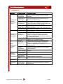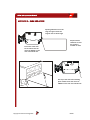
1
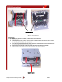
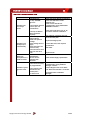
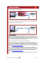
NV10 USB
OPERATIONS
MANUAL
INTELLIGENCE IN VALIDAT
Copyright Innovative Technology Ltd 2009
GA450
NV10 USB Operations Manual
2
CONTENTS
1
2
3
4
4.1
4.2
4.2.1
4.2.2
4.2.3
4.3
4.3.1
4.3.2
4.3.3
4.3.4
4.3.5
4.3.6
4.3.7
4.3.8
4.3.9
4.4
5
5.1.1
5.1.2
5.1.3
5.1.4
5.1.5
5.1.6
5.2
6
7
8
9
9.1
9.2
9.3
9.4
9.5
9.6
9.7
10
Introduction
Environment and power requirements
General description
Machine interfaces
Bezel LED’s
Hardware
Ports & Buttons
Interface connector pin details
Configuration button functions
Protocols
ESSP – Encrypted Smiley® secure protocol
Smiley® secure protocol - SSP
ccTalk® protocol – CCT
Multi-drop bus/internal communications protocol
(MDB/ICP)
Serial input/output – SIO
Parallel input and output
Pulse stream output
Binary output - BIN
Other interfaces available
Using NV10 USB Configuration Cards
Mechanical
Bezel
Bezel Installation into a machine
Cash box interface
Routine maintenance
Cleaning
Belt changing
Fault finding analysis
Re-calibration
Diagnostics
Support
Appendix
Appendix A – How to order an NV10 USB Validator
Appendix B – Extended Bezel
Appendix C – Cash Box Advice
Appendix D – Configuration Cards
Appendix E – Escrow control
Appendix F – Interface tools DA1 – DA2
Appendix G – USB to validator cable assembly
Index
Copyright Innovative Technology Ltd 2009
3
5
6
7
7
8
8
8
9
10
10
10
11
11
12
14
15
16
17
17
18
18
18
19
19
19
21
22
23
24
25
27
27
28
29
30
39
40
41
43
GA450
NV10 USB Operations Manual
3
1 INTRODUCTION
NV10 USB VALIDATOR - THE LATEST GENERATION OF SMILEY BANK NOTE VALIDATORS
This manual describes the operation of the NV10 USB Bank Note Validator as fitted with
Firmware Version 4.00 or greater.
This document is intended for those who will:
· Install the NV10 USB equipment.
· Maintain the NV10 USB equipment.
Although information is included which will allow a degree of fault diagnosis and repair, it is
recommended that for all but simple mechanical repairs, the unit must be returned to an
approved service centre for repair.
For more concise information, addressed primarily to maintenance, please refer for the
concise manual in our website.
CAUTIONS
· This product must be fitted with a 3 A (ampere) fuse before use.
· The NV10 USB validator is pin for pin compatible with NV7/8/9/10, but not pin for pin
compatible with the NV2/3/4/4x or 5 series products.
· Never exceed the recommended environmental and electrical limits.
· Do not attempt to lubricate the mechanisms as this may affect the note transport.
· Do not polish the lens as this may alter the optical characteristics.
· If the NV10 USB validator is disassembled the unit must be re-calibrated and re-initialised,
following re-assembly.
WARNING
· Only suitably trained personnel should carry out any work on this equipment in accordance
with all current local, national and international health and safety regulations.
· We recommend that you study this manual as there are many new features permitting
new uses and more secure applications.
· If you do not understand any part of this manual please contact the factory, contact details
are below, for assistance. In this way we may continue to improve our product.
· The NV10 USB Validator has been designed to minimise any performance variation over time.
Much of this is achieved by careful Hardware and Software design.
· Innovative Technology Ltd has a policy of continual product improvement. As a result the
products supplied may vary from the specification described here.
This manual can be printed in A4 or letter sizes, without loosing the scale.
This is especially important in the Appendix D – Configuration Cards.
Copyright Innovative Technology Ltd 2009
GA450
NV10 USB Operations Manual
GROUP
4
EMAIL CONTACTS
BRAZIL
[email protected]
CHINA
[email protected]
COLOMBIA
[email protected]
GERMANY
[email protected]
UNITED KINGDOM
[email protected]
SPAIN
[email protected]
UNITED STATES OF AMERICA
[email protected]
REST OF THE WORLD
[email protected]
MAIN HEADQUARTERS
Copyright Innovative Technology Ltd 2009
Innovative Technology Ltd
Derker Street – Oldham – England - OL1 4EQ
Tel: +44 161 626 9999 Fax: +44 161 620 2090
E-mail: [email protected]
Web site: www.innovative-technology.co.uk
GA450
NV10 USB Operations Manual
5
2 ENVIRONMENT AND POWER REQUIREMENTS
ENVIRONMENT
Environment
Temperature
Humidity
Minimum
+3ºC
5%
Maximum
+50ºC
95% Non condensing
Table 1 – Environmental Requirements
CAUTION:
Depending upon the environment in which it is used the NV10 USB may at some time
require re-calibration. Please refer to Chapter 6 for details of the re-calibration process.
POWER REQUIREMENTS
Electrical Supply
Supply Voltage (V DC)
Absolute Limits
MDB IF5 Version Supply
Voltage
MDB Hardware version
Supply Ripple Voltage
Supply Currents:
Sleep (Low Power Mode)
Standby
Validating
Peak Motor Stall
Interface Logic Levels
Inputs
Outputs with 2K2Ω pull up
Maximum Current Sink
Minimum
Maximum
+11.5V
+14.2V
+18V
+48V DC or 34V AC
+18V
0V
+48V DC
0.25 V @ 100 Hz
2mA
0.35 A
1A
1.5 A
Table 2 – Power Requirements
Logic Low
Logic High
0 V to + 0.5 V
+3.7 V + 12 V
0.6 V
Pull up voltage of host interface
50mA per output
Table 3 – Interface Logic Levels
CAUTION
· If the input voltage falls below 11.5 V the NV10 USB may not operate correctly (will reject
notes). The front bezel lights will flash to indicate incorrect conditions.
· It is recommended that the power supply used can supply at least 2.5 amperes.
Copyright Innovative Technology Ltd 2009
GA450
NV10 USB Operations Manual
6
3 GENERAL DESCRIPTION
The NV10 USB Bank Note Validator is a compact unit (see Figure 1), suitable for most money
machines. It will accept up to 15 different denominations of notes in the serial control mode.
The NV10 USB is designed for easy installation in most machines. To see the general
dimensions of the NV10 USB, refer to Appendix B - NV10 USB Mechanical Installation.
Figure 1 - The NV10 USB validator
Currency/ Firmware
The currency and firmware files have been combined in the new NV10 USB to simplify the
downloading of files. The NV10 USB Validator leaves the factory preset to at least one currency
so that it is ready for immediate installation. If the currency data set needs to change this may
be done using the PC based Validator Management Software. New currencies and applications
are being tested all the time, please refer to our web site or contact the factory for information
concerning specific currencies if they are not already included on our approved list.
The NV10 USB has been designed for easy installation in most machines. The “Smiliey mouth”
allows insertion of notes with one hand and simplifies the note handling mechanism.
Interface
Interfacing the validator is very simple, with the choice of the following protocols:
SSP
CCTALK
MDB
SIO
PARALLEL
PULSE
BINARY
NIS
Table 4 – Available Interfaces / Protocols
BV100 Operations Manual
For detailed information about the different interfaces see Chapter 4.3.
eSSP
7
Low power option
The NV10 USB has a low power option to reduce the power consumption when idle. To learn
more about the low power option, please refer to the Chapter 5.
PC System Specification
The ITL Validator Software has been tested and verified using Windows 2000/XP/Vista™
on a Pentium™ based PC System (© Microsoft and Intel). Full functionality cannot be
guaranteed on lower specification systems.
NV10 USB Operations Manual
Copyright Innovative Technology Ltd 2009
7
GA450
NV10 USB Operations Manual
7
4 MECHANICAL INSTALLATION
The NV10 validator is supplied with the Universal Bezel-PA231 (see figure 10).
CHANGING OR REMOVING THE BEZELS
•
•
•
Push the red Bezel Release Catch in the centre and top of the NV10.
The bezel can then be unhooked from the 4 locating points on the NV10.
To refit, hook the bezel onto the bottom 2 locating points and then lift to fit
onto the top 2 locating points on the NV10.
•
The bezel will click home into NV10 when fitted correctly.
4.1 BEZEL LEDs
The Bezel LED’s are used to indicate a variety of status signals as described below.
Number of
LONG flashes
1
2
3
4
Number of SHORT flashes
1
Note Path Open
2
Note Path Jam
Cash Box
removed
Firmware
Checksum
PSU too Low
Cash Box Jam
Interface
checksum
PSU too High
3
Unit Not
Initialized
4
EEPROM
Checksum
Dataset
Checksum
Table 5 – Bezel LED status codes
Copyright Innovative Technology Ltd 2009
GA450
NV10 USB Operations Manual
8
4.2 HARDWARE
4.2.1 PORTS AND BUTTONS
The NV10 USB interface connector is located on the left side of the unit; it has 16 pins (see
Figure 2), refer to Table 6 for the pin allocation. Two are used for the 0V and +12V power
supply and there are five outputs and five inputs, the remaining four pins are reserved for
factory use and should not be connected. An example mating connector is Molex type Part
No: 39-51-2160.
It is possible to use the special hardware versions of NV10 USB in machines operating at 110
volts or in machines operating at MDB.
The NV10 USB also has a Configuration Button located on the right hand side of the unit. The
USB cable CN392 fits into the 16 way connector, this can be used to program the NV10 USB and
for communications when used in SSP and SIO modes. When used for programming, no external
power supply is required. When used for the communications, power must be applied to the
NV10 USB cable CN392 via the 16 pin interface connector before connecting the USB cable.
4.2.2 INTERFACE CONNECTOR PIN DETAILS
The connector pin details are described below
(see table 5); they use an IDC 16-pin 0.1" pitch
header with 2 rows of 8 pins.
1
15
2
16
Figure 2 – Pin detail
Pin
1
Name
Vend 1
2
3
4
5
Vend 2
Vend 3
Vend 4
Inhibit 1
6
7
8
9
Inhibit 2
Inhibit 3
Inhibit 4
Busy
10
Escrow
11
12
13
14
15
16
USB
USB
USB
Factory use only
+Vin
0V
Description
Open collector outputs. Function changes depending on
machine interface protocol (see individual interface
descriptions for details.) Also the Pulse Steam output.
Also the Serial Output pin in SSP Serial Mode
and other serial modes.
Open collector outputs. Function changes depending on
machine interface protocol (see individual interface
descriptions for details).
Inhibit channel 1 by holding this pin HIGH. To Enable a
channel the inhibit must be held LOW. Also the serial
Input pin in SSP Serial Mode, and other serial modes.
Inhibit channel 2 by holding this pin HIGH
Inhibit channel 3 by holding this pin HIGH
Inhibit channel 4 by holding this pin HIGH
NV10 USB is validating and stacking output. Active low
while the NV10 USB is reading, transporting or stacking a
note
Operate Escrow function by holding LOW (see Appendix B
– Escrow Control for full details).
Data Plus
Data Minus
-V- Bus
Do Not Connect
Nominal 12V DC supply
0V supply
Table 6 – 16 Pin Connector Details
Copyright Innovative Technology Ltd 2009
GA450
NV10 USB Operations Manual
9
4.2.3 CONFIGURATION BUTTON FUNCTIONS
The functions available via the Configuration Function Button are detailed in Table 7.
Configuration Button
Power Status
Function
Press and Hold (>2 secs)
Powered ON
Sets NV10 USB to
Programming Mode (SSP)
Press Once (<1 sec)
Powered ON
Enables Configuration Card
Programming
Press Twice (within half a
second)
Powered ON
Current Setting Indicator
Powered OFF/ON
Resets ccTalk key to Default
setting
Press and hold as power is
applied
Table 7 – Configuration Button Functions
NV10 USB Programming Mode
Press and Hold the Configuration Button for at least 2 seconds whilst the NV10 USB is
powered up. The Bezel LED will flash rapidly to indicate that SSP is being loaded. Once this
process has finished the NV10 USB will reset. The NV10 USB will now be in Programming Mode
(SSP) and allow connection to a PC via a DA1 or DA2 adapter or connection to a DA3.
Note: This mode can only be cancelled by re-programming with a Configuration Card or via
the Validator Manager Program. Please ensure you are aware of all the NV10 USB programmed
settings before entering this mode. Failure to restore the original setting will stop the
NV10 USB from operating in the Host machine.
Configuration Card Programming Mode
Press the Configuration Button once whilst the NV10 USB is powered up. If done correctly the
Bezel LED will flash every 1 second. This will allow the insertion of a Configuration Card to
change the Firmware Protocol in the NV10 USB. (See chapter 4.4 Using NV10 USB Configuration
Cards for full details). This mode can be cancelled by again pressing the Configuration
Button once.
Current Setting Indicator Mode
Press the Configuration Button twice within half a second whilst the NV10 USB is powered up.
The NV10 USB Bezel LED will then perform a series of flashes to indicate the current settings
within the validator. (See Program Check Procedure, Appendix D - Configuration Cards)
Encryption Key Reset Function (ccTalk®)
Note: This function will only be possible if the NV10 USB is programmed to ccTalk® mode. It is
not possible to reset the key from SSP mode. Press and hold the Configuration Button whilst the
NV10 USB powered is off. Apply the power and keep the button pressed for several seconds. The
ccTalk Encryption key will now be restored to the default setting.
10
Copyright Innovative Technology Ltd 2009
GA450
NV10 USB Operations Manual
10
4.3 PROTOCOLS
ITL strongly recommends the use of an encrypted Serial protocol (Preferably eSSP) to achieve
the highest security.
4.3.1 eSSP - ENCRYPTED SMILEY® SECURE PROTOCOL
We have now developed encrypted SSP for the NV10 USB banknote validator as it is our opinion
that encrypted SSP is now necessary in this advanced technological age. The encryption of SSP
protocol will ensure superior protection and reliability of the data, which is transferred between
validator and host machine. The encryption key is 128 bits long, and is divided into two parts.
The lower 64 bits are fixed and specified by the machine manufacturer, allowing the
manufacturer to control which devices are used in their machines. The higher 64 bits are
securely negotiated by the slave and host at power up, ensuring each machine and each session
are using different keys. This encryption algorithm is approved by the US military for its
advanced security.
We have new hardware interfaces available to enable eSSP banknote validators to be used in
machines without the need of updating the machine software. The interface is mounted close to
the control board, and converts the connection to the banknote validator to serial eSSP, giving
maximum security along the length of the cable.
4.3.2 SMILEY® SECURE PROTOCOL - SSP
NOTE: Please refer to the Smiley® Secure Protocol (SSP) Specification (ITL Drawing GA138) on
the web site for full details of the SSP protocol. To use SSP mode, the SSP interface must be
programmed into the validator via the Configuration Cards (See Appendix D - Configuration
Cards) or via the ITL BNV Currency Manager Program, or by pressing and holding the
Configuration Button for more than 2 seconds.
SSP is a secure serial interface specifically designed to address the problems experienced by
cash systems in gaming machines. Problems such as acceptor swapping, reprogramming
acceptors and line tapping are all addressed. This interface is recommended for all new designs.
The interface uses a master slave model; the host machine is the master and the peripherals
(note acceptor, coin acceptor or coin hopper) are the slaves. Data transfer is over a multi-drop
bus using clock asynchronous serial transmission with simple open collector drivers.
The integrity of data transfers is ensured through the use of 16 bit CRC checksums on all
packets. Each SSP device of a particular type has a unique serial number; this number is used to
validate each device in the direction of credit transfer before transactions can take place.
Commands are currently provided for coin acceptors, note acceptors and coin hoppers. All
current features of these devices are supported.
For detailed information and full protocol specification please refer to SSP Interface
Specification ITL (GA138), this is available from the ITL website www.innovativetechnology.co.uk.
To help in the software implementation of the SSP, ITL can provide DLL controls and Visual
Basic applications on request. Please contact [email protected] for
more information.
Copyright Innovative Technology Ltd 2009
GA450
NV10 USB Operations Manual
NV10 USB Operations Manual
11
11
4.3.3 CCTALK® PROTOCOL – CCT
The NV10 USB supports the ccTalk serial protocol for easy interfacing with host machines that
support this protocol. To use ccTalk® mode, the CCT interface must be programmed into the
validator via the Configuration Cards (See Appendix D - Configuration Cards) or via the ITL BNV
Currency Manager Program.
Pin out connections on NV10 USB for ccTalk are shown
(see Figure 6) looking at the connection pins on the
NV10 USB interface connector as defined
in the ccTalk specification. It is recommended that all
communications with the note validator must be
encrypted using the encryption key, the default
encryption key will be printed on the label
of the NV10 USB. To reset the Encryption key to its
default value sees Chapter 4.2.3. NOTE: For detailed
information and full protocol specification please refer
to www.cctalk.org.
Figure 3– ccTalk connection pins
4.3.4 MULTI-DROP BUS/INTERNAL COMMUNICATIONS PROTOCOL (MDB/ICP)
To use the MDB mode an MDB NV10 USB or an IF5 interface box can be used. The MDB
interface must be programmed into the validator via the Configuration Cards (See Appendix
D - Configuration Cards) or via the ITL BNV Currency Manager program.
Note:
· An IF5 cannot be used with an MDB NV10 USB.
· A standard NV10 USB can only be used in MDB with the addition of an IF5 interface.
· Please refer to the Multi-Drop Bus specification for the suggested current drive circuits
available.
· The NV10 USB supports the MDB protocol version 1, level 1.
· For detailed information and full protocol specification please refer to www.vending.org
MDB defines a serial bus interface used
in electrically controlled vending machines
(see Figure 7).
This is a 9600 Baud Master-Slave system where the NV10
USB Banknote Validator is a slave to a master controller. A
master has the capability of communicating with 32
peripherals or slaves. The master is defined as the
Vending Machine Controller (VMC). The NV10 USB
banknote Validators have a unique address – 00110XXX
binary (30H).
The VMC polls the bus to detect presence
of the NV10 USB Validator or get information on
the current status of the validator.
Figure 4 – MDB Opto Isolated input
output circuits
The validators will respond when asked for activity with an acknowledgment, a negative
acknowledgment or a specific reply, depending on its current status. Bus crashes are
avoided as the Validators respond to being polled only by the VMC.
The international country code must be set for the country in which the Validators will be
operating. This is either the international telephone code for that country, or the country
code taken from ISO4217. The code is represented as two bytes. The initial digit signifies
the source of the code. 0 signifies the telephone code is used, 1 signifies ISO4217 has been used.
Copyright Innovative Technology Ltd 2009
GA450
NV10 USB Operations Manual
12
For the USA the country code is 00 01, or 18 40
For Great Britain the code is 00 44, or 18 26.
The scaling factor must also be specified for each Validator. All accepted note values must
be evenly divisible by this number.
· This number would be set to 100 (Hex 64) for the Euro or Great Britain.
· The number would be set to 1000 (Hex 03E8) for Colombia.
The number of decimal places must also be programmed for each Validator
· The number would be set to 2 for Euro or USA
· The number would be set to 3 for Colombia
Adopting the numbers above.
· £5 would be displayed as 5.00
· £10 would be displayed as 10.00
· $1 would be displayed as 1.00
· 1K Colombia would be displayed as 1.000
4.3.5 SERIAL INPUT/OUTPUT – SIO
Existing Smiley® NV4 - NV10 users may already be using the serial input/output facility
in conjunction with the parallel inputs. The NV10 USB Validator also supports this system.
However this interface is not recommended for new designs, the Smiley® Secure Protocol
SSP interface is recommended.
CAUTION
· The NV10 USB does not support the simple serial data out only mode as available on NV4
and earlier models NV2 and NV3. It only supports the serial data input/output mode.
· The host machine does not echo messages back to the validator.
· The NV10 USB does not operate in true RS232 mode. (Only TTL level).
To use Serial Input/Output mode, the SIO interface must be programmed into the validator
via the Configuration Cards (See Appendix D – Configuration Cards) or via the ITL BNV
Currency Manager Program.
There are 4 different combinations of SIO available:
SIO 300 Baud
SIO 300 Baud (Disabled at Start up) - A software enable must be sent to enable the validator.
SIO 9600 Baud
SIO 9600 Baud (Disabled at Start up) - A software enable must be sent to enable the validator.
Figure 5 – Typical serial output: Transmission of the value 20 (decimal), note not recognized
Figure 6 – Typical serial output: Transmission of the value 20 (decimal), note not recognized
Copyright Innovative Technology Ltd 2009
GA450
13
13
NV10 USB Operations Manual
13
The NV10 USB will receive and transmit the following event codes.
Recognised Receive Codes to
NV10 USB
MESSAGE
Inhibit C1
Inhibit C2
Inhibit C3
Inhibit C4
Inhibit C5
Inhibit C6
Inhibit C7
Inhibit C8
Inhibit C9
Inhibit C10
Inhibit C11
Inhibit C12
Inhibit C13
Inhibit C14
Inhibit C15
Inhibit C16
Un-inhibit C1
Un-inhibit C2
Un-inhibit C3
Un-inhibit C4
Un-inhibit C5
Un-inhibit C6
Un-inhibit C7
Un-inhibit C8
Un-inhibit C9
Un-inhibit C10
Un-inhibit C11
Un-inhibit C12
Un-inhibit C13
Un-inhibit C14
Un-inhibit C15
Un-inhibit C16
Enable serial
escrow mode
Disable serial
escrow mode
Accept escrow
Reject escrow
Status
Enable all
Disable all
Disable escrow timeout
Enable escrow timeout
Request firmware
Request dataset
DECIMAL
VALUE
131
132
133
134
135
136
137
138
139
140
141
142
143
144
145
146
151
152
153
154
155
156
157
158
159
160
161
162
163
164
165
166
170
Transmitted codes from NV10 USB
MESSAGE
Note Accept on C1
Note Accept on C2
Note Accept on C3
Note Accept on C4
Note Accept on C5
Note Accept on C6
Note Accept on C7
Note Accept on C8
Note Accept on C9
Note Accept on C10
Note Accept on C11
Note Accept on C12
Note Accept on C13
Note Accept on C14
Note Accept on C15
Note Accept on C16
Note Not Recognised
Mechanism running slow
Strimming attempted
Channel 5 Note Rejected (fraud channel)
STACKER Full or Jammed
Abort During Escrow
Note may have been taken to clear jam
Validator Busy
Validator Not Busy
Command Error
DECIMAL
VALUE
1
2
3
4
5
6
7
8
9
10
11
12
13
14
15
16
20
30
40
50
60
70
80
120
121
255
171
172
173
182
184
185
190
191
192
193
Table 8 - Receive and Transmit Codes
Copyright Innovative Technology Ltd 2009
GA450
NV10 USB Operations Manual
14
Event
Validator
Note entered into validator
Note accepted channel 2
Validator Busy
Validator Ready
Accept on channel 2
Validator Busy
Validator Ready
Note not recognised
Validator Ready
Inhibit C4
Channel 4 inhibited
Uninhibit C4
Channel 4 inhibited
Note entered into validator
Note not recognised
Validator has returned note
Software Inhibit Channel 4
Software Enable Channel 4
Status Report
3 byte status message
Status Requested
Inhibit status Channels 1-8
Inhibit status Channels 9-16
Escrow On (=1) / Off (=0)
Turn on Escrow Mode
Note accept in Escrow Mode
Note entered into validator
Note Accepted Channel 2
Decimal
Value
120Î
121Î
2Î
120Î
121Î
20Î
121Î
Í134
134Î
Í154
154Î
Í182
182Î
Byte 1Î
Byte 2Î
Byte 3Î
Í 170
Escrow Mode Enabled
170Î
Validator Busy
Validator Ready
Accept on Channel 2
120Î
121Î
2Î
Í172
Accept Escrow
Accept on Channel 2
Host
Inhibit C4
Uninhibit C4
Status Request
Enable Escrow
Mode
Accept Note in
Escrow
172Î
2Î
Example transactions are shown below.
14
NV10 USB Operations Manual
Table 9 – Example Protocols
14
4.3.6 PARALLEL INPUT AND OUTPUT
To use Parallel Output for 4-note/channel acceptance the Parallel interface must be
programmed into the validator via the Configuration Cards (See Appendix D – Configuration Cards)
or via the ITL BNV Currency Manager Program.
Vend Signals: (Pins 1 to 4). The four channels have their own individual outputs. If a note
is recognised then the relevant Vend line is set low for a period of 100 ± 3 ms. Pulses
outside these limits should be rejected as a precaution against false triggering.
Busy Output: (Pin 9). This is a general-purpose busy signal. It is active low while the
NV10 USB is in operation.
Copyright Innovative Technology Ltd 2009
GA450
NV10 USB Operations
NV10 USB Operations Manual
15
Escrow Control: (Pin 10) Hold this pin Low to enable the single note escrow function. (See
Appendix E – Escrow Control). If the host machine aborts the transaction by setting the
corresponding inhibit input high, the note is returned immediately.
The host machine can force the return of the note to the customer by setting the inhibit
line high, at any time before the end of the 30 second time-out. Setting high all the inhibits causes
a note reject.
In the event of a note being forcibly removed from the mouth of the NV10 USB during the 30second interval, the NV10 USB will go out of service for 45 seconds.
Inhibit Operation: (Pins 5 – 8) Channels 1 to 4 have their own inhibit input to allow the
host machine to refuse specified notes. To inhibit a channel, the relevant inhibit input must be held
high. To enable a channel, the corresponding inhibit must be latched low so that notes may be
accepted.
If all four inhibits are high simultaneously then the NV10 USB will be disabled. In this state
the bezel LED will not illuminate and if a note is inserted the motor will run in reverse
preventing the insertion of the note.
All four inhibits may be connected together to create a ‘global’ inhibit. In this way the
NV10 USB may be brought in and out of operation by the host machine.
It is possible to operate the NV10 USB in Low power mode with the Parallel interface. For
further details please see Chapter 5.
4.3.7 PULSE STREAM OUTPUT
To use pulse stream output for acceptance of up to 16 note/channel acceptance, The
Pulse interface must be programmed into the validator via the Configuration Cards (See
Appendix D – Configuration Cards) or via the ITL BNV Currency Manager Program.
Vend Signal: (Pins 1) When a note is recognised vend 1 will pulse a pre set number
of times, the number of pulses can be set via the ITL BNV Currency Manager Program
(and set to default values with supplied dataset). The pulse width can be set either with
the ITL BNV Currency Manager Program or via the Configuration Cards (See Appendix D
- Configuration Cards)
Busy Output: (Pin 9). This is a general-purpose busy signal. It is active low while the
NV10 USB is in operation.
Escrow Control: (Pin 10). No escrow function in this mode
Inhibit Operation: (Pins 5 – 8) Channels 1 to 4 have their own inhibit input to allow the
host machine to refuse specified values of notes. To inhibit a channel, the relevant inhibit
input must be held high. To enable a channel, the corresponding inhibit must be latched
low so that notes may be accepted.
If all four inhibits are high simultaneously then the NV10 USB will be disabled. In this state
The bezel will not illuminate and if a note is inserted the motor will run in reverse preventing the
insertion of the note.
NV10 USB Operations Manual
Copyright Innovative Technology Ltd 2009
16
GA450
NV10 USB Operations Manual
16
Note: Channels higher than four cannot be individually inhibited, but will be globally
inhibited if inhibits 1 to 4 are inhibited.
It is possible to operate the NV10 USB in Low power mode with the Pulse interface. For
further details please see Chapter 5.
Credit Hold Function:
If this function is enabled in pulse mode by Configuration card or ITL BNV Currency
Manager Program, the validator will take the note as normal but then wait until the
escrow line is toggled low/high before. It will then give out the number of pulses per dollar
as set on the programming card. After the pulses have been given, the validator will then
wait for another low/high toggle until the full value of credit pulses are given.
For example with a setting of 2 pulses per dollar, a five dollar bill will give 2 pulses, 5
times.
A Typical use of this option would be for a Pool table with a game price of $1. You
could insert a $5 note and press a button that toggles the escrow line and releases the
pool balls, this would then allow you to play the first game. The Validator holds onto the
remaining credits until the game has finished and the button is pressed again allowing the
next game to begin, this continues until all the credits have been used.
The busy line remains low throughout the whole process and the validator remains
inhibited until all pulses are given.
4.3.8 BINARY OUTPUT – BIN
To use Binary mode the Binary interface must be programmed into the validator via the
Configuration Cards (See Appendix D – Configuration Cards) or via the ITL BNV Currency
Manager Program.
In the event that the machine needs more than 4 notes to be recognised, but the host
machine cannot take advantage of the serial communication methods then the NV10 USB can be
set to give a binary pattern output on the four parallel output pins. If the NV10 USB is set to binary
mode it will issue the vend signals as a binary pattern on the parallel outputs for 100 ± 3 ms. In
this way a maximum of 15 different notes can be accepted and 4 notes individually inhibited.
Vend Signals: (Pins 1 to 4). The four channels have their own individual outputs. If a note
is recognised the binary representation of the channel number will be pulled low for 100
± 3 ms. Pulses outside these limits will be rejected as a precaution against false triggering
due to noise.
Busy Output: (Pin 9). This is a general-purpose busy signal. It is active low while the
NV10 USB is in operation.
Escrow Control: (pin 10). Hold this pin Low to enable the single note escrow function. (See
Appendix E – ESCROW Control).
If the host machine aborts the transaction by setting the corresponding inhibit input high
on pin 10, the note is returned immediately.
The host machine can force the return of the note to the customer by setting the inhibit
line high, at any time before the end of the 30 second time-out. Setting all the inhibits high
causes a note reject.
In the event of a note being forcibly removed from the mouth of the NV10 USB during the
30-second interval, the NV10 USB will go out of service for 45 seconds.
Copyright Innovative Technology Ltd 2009
GA450
NV10 USB Operations Manual
17
Inhibit Operation: (Pins 5 – 8) Channels 1 to 4 have their own individual inhibit input to
allow the host machine to refuse specified values of notes. To inhibit a channel, the
relevant inhibit input must be held high. To enable a channel the corresponding inhibit
must be latched low so that notes may be accepted.
If all four inhibits are high simultaneously then the NV10 USB will be disabled. In this state
the bezel will not illuminate and if a note is inserted the motor will run in reverse
preventing the insertion of the note.
Note: Channels higher than four cannot be individually inhibited, but will be globally
inhibited if inhibits 1 to 4 are inhibited. It is possible to operate the NV10 USB in Low
power mode with the Binary interface. For further details please see the next chapter.
4.3.9 OTHER INTERFACES AVAILABLE BY REQUEST FROM ITL
Any queries regarding interfaces not mentioned in this manual should be made to
[email protected]
4.4 USING NV10 USB CONFIGURATION CARDS
The Configuration Cards offer the following functions:
• Select required Communication Interface (SSP, ccTalk, Parallel etc).
• Adjust the channel and pulse configuration on a pre-programmed NV10 USB to your own
requirements.
Programming the NV10 USB with the configuration cards is enabled via the ‘Configuration
Button’ on the right hand side of the NV10 USB (see Chapter 4.2.3). (For details on how to
complete the configuration cards please see Appendix D – Configuration Cards)
Instructions
1) Press the Configuration button once whilst the validator is powered up.
2) The bezel LEDs will now flash with a steady heartbeat until a Configuration Card is
entered.
3) Once the Configuration Card has been entered the validator reads the card and
immediately returns it.
4) The LEDs then flash rapidly whilst the interface is being changed. If the LEDs flash a
number of times slowly, it is an indication of an error (For details of the Error Flash
Codes please see Appendix D – Configuration Cards).
5) When the changes are complete the validator resets.
If a configuration card is not entered, this function can be cancelled by pressing the button
again once.
It is now possible to check the programmed settings of the NV10 USB by pressing the
Configuration button twice within half a second. (For details see Appendix D – Configuration Cards)
Copyright Innovative Technology Ltd 2009
GA450
NV10 USB Operations Manual
18
18
NV10 USB Operations Manual
5 MECHANICAL
5.1.1 CHANGING OR REMOVING THE BEZELS
•
•
•
Push the red Bezel Release Catch in the centre and top of the NV10.
The bezel can then be unhooked from the 4 locating points on the NV10.
To refit, hook the bezel onto the bottom 2 locating points and then lift to fit
onto the top 2 locating points on the NV10.
•
The bezel will click home into the NV10 USB when fitted correctly
5.1.2 FITTING THE BEZEL INTO A MACHINE
CAUTIONS:
•
ENSURE THERE IS A CLEARANCE AROUND THE INITIAL EXIT (SEE DRG GA334 IN
APPENDIX A) SO THERE IS NO OBSTRUCTION TO THE BANKNOTES AS THEY
ARE BEING READ BY THE NV10.
•
A SUITABLE CASH BOX IS NEEDED SO THAT THE NOTES SECURELY STORE AWAY
FROM THE NOTE EXIT (SEE APPENDIX C), TO PREVENT NOTES ACCUMULATING
AT THE NOTE EXIT.
Note Path
Bezel Release
Access Buttons
Catch
Programming
button
Locking Nuts And
Bolts
PA231 Bezel
Figure 7 – Bezel and NV10 Installation
•
Remove the 4 nuts, 2 metal clamps, star washers and 2 bolts from each side of the
bezel as above (see figure 10).
•
Place PA231 through the aperture in the door of the machine from the front.
•
Fit the two metal clamps and star washers and tighten the nuts onto the bolts
(recommended torque 25cN per metre).
•
Fit the main bezel assembly onto the bolts with the black part to the top. Fit the star
washers and tighten the nuts onto the bolts (recommended torque 25cN per metre).
Copyright Innovative Technology Ltd 2009
GA450
NV10 USB Operations Manual
19
5.1.3 CASH BOX INTERFACE
It is important that there is sufficient space for the ‘’initial exit’’ and ‘’final exit’’ of notes
from the NV10 note path, before entry into the cash box/chute without any obstructions
(see Appendix C). For help on installing the NV10 into a new design please contact:
[email protected].
5.1.4 ROUTINE MAINTENANCE
The NV10 Validator has been designed to minimise any performance variation over time.
Much of this is achieved by careful hardware and software design. However, depending
upon the environment the NV10 may at some time require cleaning, belt changing or
note path clearing.
5.1.5 CLEANING
CAUTION: DO NOT USE SOLVENT BASED CLEANERS SUCH AS ALCOHOL, PETROL,
METHYLATED SPIRITS, WHITE SPIRIT or PCB CLEANER. THIS WILL RESULT IN PERMANENT
DAMAGE TO THE VALIDATOR, ONLY USE A MILD DETERGENT.
Remove the NV10 from its bezel. Push the 2 red Note Path Access Buttons on the sides of
the NV10 downwards and then inwards towards the body of the NV10 (see figure 9) and lift
to expose the note paths, place them on a clean dry surface. The note path will now be exposed
for cleaning, (see figure 11).
Carefully wipe the surfaces with a soft lint free cloth that has been dampened with a water
and mild detergent solution (i.e. household washing up liquid). Take particular care around
all the sensor lenses (see figure 11), ensuring they are clean and dry. Clean any metal debris
that may be attached to the magnetic sensor.
If a lens has become badly scratched do not attempt to polish it. Contact ITL for further advise,
as there may be damage to the optical properties of the lens.
CAUTION: WHEN CLEANING THE ‘’RECESSED’’ FRONT SENSOR, USE A SMALL SOFT BRUSH OR
COTTON WOOL BUD.
Copyright Innovative Technology Ltd 2009
GA450
NV10 Operations Manual
NV10 USB Operations Manual
20
Optical Sensors
Figure 8 – NV10 Sensors
Belt Cleaning
1. Ensure the validator is enabled (i.e. Bezel lights are illuminated)
2. Remove Bezel.
3. Insert a piece of paper, which is narrower than the width between the two belts, in the centre
of the note path to activate the drive motor.
4. Use a lint free cloth dampened with water containing a mild detergent such as dish detergent
and hold it against each drive belt as is turns.
5. Repeat steps 3 and 4 until all dust and debris has been removed from both belts.
6. Repeat step 3 using a DRY lint free cloth to remove any excess moisture.
Insert Paper
Copyright Innovative Technology Ltd 2009
GA450
NV10 USB Operations Manual
21
5.1.6 BELT CHANGING
•
•
•
•
•
•
With the NV10 note paths exposed (see figure 11) place the unit on a clean dry surface.
Remove the lower cover plate by lifting up the retention catch and carefully sliding it
back (see figure 12).
Push the 2 belt tension springs inwards then slide each belt off the drive unit body,
smallest wheels first.
Replace the belts by fitting them over the drive unit body legs, smallest wheels first.
Place the lower cover plate into the locating slots (2 each side) pushing forward and
down, the plate will ‘’click’’ confirming correct insertion.
Connect the upper and lower note path back together.
Belts
Lower Cover Plate
Locating
Slots
Retention Catch
Drive Unit
Body
Drive Belts
Belt Tension Springs
Figure 9 – NV10 Belt Access
NV10 Operations Manual
Copyright Innovative Technology Ltd 2009
GA450
NV10 USB Operations Manual
22
5.2:FAULT FINDING ANALYSIS
PROBLEM
CHECK
Is the Bezel lit?
Are any “STATUS”
lights lit?
Validator will
not accept
notes
Is the problem with all
notes or just one
denomination
Validator runs
slowly and/or
intermittently
Notes are
accepted but no
credit received
Is the Top to Bottom
cable connected
properly?
Check note paths for
foreign objects
Check note path for
damage
Check Voltage level of
supply
Check drive belts are
fitted correctly
Ensure that there is no
grease on the drive
belts
Is the PSU within
specification?
Has the correct
interface been
selected?
Is the correct currency
file programmed?
Validator rejects
genuine notes
Is the required note
contained in the
Currency file?
Are sensors ok
Copyright Innovative Technology Ltd 2009
SOLUTION
Check the Power Supply specification
Check the LED Status codes
(Chapter 4.2).
Check correct interface is
programmed in using VALIDATOR
MANAGER software.
Check the inhibit lines (pins 5 –8)
from Host machine to Validator.
Test cable for continuity and refit.
Clean the note path.
Replace damaged parts
Ensure PSU meets the required
specification
Refit belts
Replace belts
Check Power Supply specification
Check correct Currency is
programmed in using Validator
Manager software
Contact Support with “Issue Date”
and “Note Denomination” for details
Run Diagnostics in Validator
Manager
GA450
BV20 Operations Manual
BV20 Operations Manual
NV10 USB Operations Manual
23
24
23
6 RE-CALIBRATION
The NV10 USB has an in-built self-calibration system that maintains the optical sensors at
their best operating point.
However if the NV10 USB is disassembled for any reason it will need to be re-calibrated.
Re-calibration may only be performed under license from ITL, contact
[email protected] for further details.
This can be performed in conjunction with the diagnostics software option in the ITL BNV
Currency Manager Program and help menus supplied with this program.
Copyright Innovative Technology Ltd 2009
GA450
NV10 USB Operations Manual
24
7 DIAGNOSTICS
Symptom
All notes are
rejected
(Bezel LED’s
are on)
Possible Cause
Incorrect
currency file
programmed
Notes are not
included in the
currency file
Notes are
inhibited by the
host machine
Bill path
obstructed
Reader module is
not fully inserted
No Power
Notes are not
taken in (no
bezel LED’s)
Incorrect
interface is
programmed
Reader module is
not fully inserted
Incorrect
interface is
programmed
Notes
accepted but
no credit
given
Acceptor
runs slowly
or
intermittently
Bezel LED’s
are flashing
Motor
continues to
run
Corrective Action
Check that the required dataset is programmed
into the validator using the validator manager
software.
Check that the required note denomination and
issue is included in the currency file using the
validator manager software.
Ensure the machine is ready to accept notes. If a
coin hopper is in the machine, ensure it is not
empty. Ensure the maximum allowed credit on the
host machine has not been exceeded.
Check for necessary clearance for note ejection
after acceptance.
Ensure the reader module is fully inserted into the
main body of the validator.
Ensure the correct specification of power is applied
to the validator.
Check which interface is programmed into the
validator by double clicking the configuration
button. The displayed code indicates which
interface is programmed as described in Appendix
D – Configuration Cards)
Ensure that the validator reader module is fully
clipped in to the validator housing.
Check which interface is programmed into the
validator by double clicking the configuration
button. The displayed code indicates which
interface is programmed as described in document
number GA713.
Ensure correct supply and sufficient current. Also
check for necessary clearance for note ejection
after acceptance.
Ensure no foreign objects are obstructing the
sensors.
Clean the bill path
Power supply
outside
specification
Rear note detect
sensor obscured
Foreign objects
in the bill path
Incorrect voltage
Ensure correct supply and sufficient current
level of supply
Damage in the
Replace necessary components
unit
See chapter 4.1 for details of LED status signals
Foreign object or
note is stuck in
the note path
Copyright Innovative Technology Ltd 2009
Ensure the note path is clear and reset the
validator. It may also be necessary to reset the
host machine.
GA450
NV10 USB Operations Manual
25
8 SUPPORT
The following support tools are available for use with the NV10 USB Bank Note Validator:
· Configuration Cards.
· ITL Bank Note Validator Currency Manager Software.
· Validator Programming System (DA3)
· Downloads from the Innovative Technology Ltd website: www.innovative-technology.co.uk
· E-mail Support via [email protected]
Configuration Cards
For full details of the use and function of the Configuration Cards please see Appendix D
- Configuration Cards.
ITL Bank Note Validator Currency Manager
Notes:
· The Validator must be set to Programming Mode (SSP) when connected to a computer or
DA3 and then returned to the original Settings when complete (See Chapter 4.2.3).
· ITL BNV Currency Manager 3.2.0 or Higher must be used to access the NV10 USB functions.
· Datasets can only be downloaded to a NV10 USB with the correct bezel width for the
currency. For example a USD dataset can only be downloaded to a 66 mm NV10 USB.
A Euro dataset can only be downloaded to a 72 mm NV10 USB.
The ITL BNV Currency Manager software offers the following functions:
· Program the Validator by downloading pre-prepared currency data via the DA1 or DA2 kit.
· Check the firmware version and currency set already loaded on a NV10 USB unit.
· Adjust the channel and pulse configuration on a pre-programmed NV10 USB to your own
requirements.
· Download a new version of firmware onto the NV10 USB.
· Use diagnostic functions to check Validators operation.
The software will run on an IBM compatible Personal Computer with Pentium™ processor
or equivalent (see the General Description chapter for operating system requirements).
The NV10 USB can be connected directly via the USB port, or with either a DA1 kit fitted to the
serial port or DA2 kit fitted to the USB port. (See Appendix F – Interface Tools DA1 – DA2)
Validator Programming System (DA3)
The DA3 is a programming system designed to enable the programming of ITL Bank Note
Validators in the field without the use of a PC.
Once the DA3 has been programmed the user can:
· Reprogram the validator to accept a different currency using the BNV Override Download
function.
· Test the functionality of the validator away from the Host machine.
For full DA3 operation and functionality details please refer to the DA3 User Manual
(Document number GA339)
Note: When using the DA3 BNV Match Download function, any pulses and channel
allocations programmed into the NV10 USB will not be retained. The user must ensure that
the required dataset options are set and saved before programming the DA3.
When programming a NV10 USB using the DA3 BNV Override Download function, the firmware
interface will not be changed. If a different interface is required, the user must use a configuration
card to select the required interface.
BV100 Operations Manual
Copyright Innovative Technology Ltd 2009
24
GA450
NV10 USB Operations Manual
26
Internet Website Support
The Innovative Technology Ltd website provides the means to download new and updated
currency sets and new versions of firmware for the NV10 USB. You can obtain these along with
technical bulletins by visiting www.innovative-technology.co.uk
E-mail Support
If the data you require is not available over the Internet Innovative Technology supports
an e-mail system to help customers with unusual requirements. The address is:
[email protected]
NV10 USB Operations Manual
Copyright Innovative Technology Ltd 2009
26
GA450
NV10 USB Operations Manual
27
APPENDIX A – HOW TO ORDER A NV10 USB VALIDATOR
To order a validator, please print and fill the order form, presented in the next page, and send it
to our nearest office. You may send it by fax or email. To find our contact information, please go
to our website or refer to the introduction chapter in this document. If you do not know which
office to send the order form, just send it to our main head quarter:
INNOVATIVE TECHNOLOGY LTD
Derker Street – Oldham – England - OL1 4EQ
Tel: +44 161 626 9999 Fax: +44 161 620 2090
E-mail: [email protected]
Web site: www.innovative-technology.co.uk
If you have any questions about the information required for the order form, please see chapter
3 General Description. If you still have any questions, or you want to know more about other
products and possibilities, do not hesitate to contact your nearest dealer. We offer a wide range
of products and accessories such as alternative validators, programming kits, interfaces,
connecting cables, bezels and other elements. Please contact your nearest office for more
information.
NV10 USB
Date:
Customer Details
Company
Phone
Number:
Country:
Contact
Person
Issue No.
Customer
Part No:
NV10
USB
Product
Dataset
Firmware
Version
Firmware
Interface
ccTalk
Encryption
Key
APPROVED
Customer:
Copyright Innovative Technology 2009
Innovative Technology:
GA450
APPENDIX B – EXTENDED BEZEL
Copyright Innovative Technology 2009
GA450
NV10 USB Operations Manual
29
APPENDIX C – CASH BOX ADVICE
Opening dimension must be
large enough to allow the
longest note to fall through
Front face of the cash
box should fit into the
recess of PM397 on the
rear of the NV10 unit.
Depth must be
sufficient to store
the required
number of notes
The top of the cash chute dividing
plate should fit into the recess of
PM397 on the rear of the NV10 unit.
Copyright Innovative Technology 2009
GA450
NV200 Operations Manual
NV10 USB Operations Manual
31
30
APPENDIX D – CONFIGURATION CARDS
The following pages contain the information corresponding to the document number
GA713. To print the cards, ensure that the page scaling is set to ‘none’. Always ensure
that the card has printed with the correct dimensions before use.
BV CONFIGURATION OPTION PROGRAMMING
Instructions for use
1) Select correct width card for bezel. Cut card around outline – check measurements
as printed. Check print options ‘Page scaling’ is set to ‘none’ when printing a pdf file to
ensure correct size.
2) Fill in sections as required. Take care to fill in the selections correctly, keep inside
the lines and fill boxes fully as example below.
3) Power up NV10 USB and allow it to reset.
4) Click ‘function’ button on BV to access Configuration Mode, BV bezel LEDs should be
flashing at 1 second intervals.
5) Enter card into BV in direction indicated by arrows.
6) Card will be returned and if configuration was good the bezel LEDs will flash rapidly
while programming takes place. take care to ensure the power is not removed at this
stage, the bv may suffer permanent damage!! The BV will then reset.
7) If an error occurs has occurred the card will be rejected and the bezel LEDs will flash
slowly a number of times to indicate the cause of the error. (see table below)
8) important check that the configuration requested has been set in the NV10 USB
before use.
Flash
2
3
4
5
6
7
8
9
Error
Invalid card read – card entered wrong way round, card mis-read or card
wrong version
No interface selection was detected on card
Multiple interface selections detected
Invalid interface selected – the selected interface is not available for
this NV
Selected interface not compatable with NV version
Pulse configutration error. Selected pulse options invalid.
ccTalk configuratrion error. Selected cctalk options invalid (ccTalk 8 bit
chk not allowed without ccTalk Plain)
Low power mode not available on this NV version
BV100 Operations Manual
Copyright Innovative Technology 2009
29
GA450
NV10 USB Operations Manual
31
Program check procedure
To check settings on a programmed unit:
1.
2.
3.
Power on unit
Click program set button on unit twice (like double click on mouse)
Monitor bezel led and check flash codes
Flash
count
Pulse
high
Pulse
low
Pulse
per
dollar
SSP
Pulse
1
2
ms/10
ms/10
value
MDB
IF30
IF31
ccTalk
3
4
5
6
SIO
Parallel
spare
NIS
IF32
spare
spare
spare
7
8
9
10
11
12
13
14
High
speed
Disabled
ccTalk
plain
Low
power
Binary
Credit
hold
3
flash
1
flash
1 flash
2
flash
2 flash
1 flash
1 flash
For example
A pulse interface with 50ms high, 100ms low, 2 pulse per dollar will flash 2,5,10,2
A SSP interface will only ever flash once
A ccTalk interface with 16 bit checksum, no encryption will flash 6,1
A ccTalk interface with 8 bit checksum, no encryption will flash 6,1,2
A Binary interface will flash 8,1
Copyright Innovative Technology 2009
GA450
This page is intentionally blank
Copyright Innovative Technology 2009
GA450
Copyright Innovative Technology 2009
GA450
This page is intentionally blank
Copyright Innovative Technology 2009
GA450
Copyright Innovative Technology 2009
GA450
Below are some typical examples of completed Configuration Cards.
Note: These Configuration Cards are samples and should not be copied for programming use.
Please see document GA713 for useable cards.
SSP
Copyright Innovative Technology 2009
Parallel
Binary
GA450
Note: These Configuration Cards are samples and should not be copied for programming use.
Please see document GA713 for useable cards.
Encrypted ccTalk
Copyright Innovative Technology 2009
Unencrypted ccTalk
with 16-bit Checksum
Pulse – Pulse width
50/100 mS
4 Pulses per Dollar
GA450
Note: These Configuration Cards are samples and should not be copied for programming use.
Please see document GA713 for useable cards.
SIO 300-Baud
SIO 300-Baud
Starts Disabled
Copyright Innovative Technology 2009
SIO 9600-Baud
SIO 9600-Baud
Starts Disabled
GA450
NV10 USB Operations Manual
39
9.5 APPENDIX E – ESCROW CONTROL
The NV10 USB has a single note escrow facility (pin 10) used in Parallel and Binary
modes. This allows the Validator to hold onto the note once accepted, and then only
stack the note into a cash box when the host machine confirms that the Vend operation
has been completed. If no confirmation of the Vend is received then the note will be
returned to the customer after 30 seconds, (see Figure 11).
30sec Max.
Do not wait more
than 30 seconds for
the 2nd vend
confirmation signal
Escrow
Vend Signal
100ms
100ms
Escrow
Inhibit rejection can be
at any time during the
30 second decision
period after completion
of the vend
Vend Signal
Inhibit
Figure 10 - Escrow Timing Diagram for Parallel Vends
If the host machine itself aborts the transaction by setting the corresponding inhibit
input high, the note is returned immediately. The sequence of operations is as follows:
· Pin 10 held low awaiting note insertion.
· Note inserted. Validator issues a 100 ms pulse on the appropriate channel.
· The host machine initiates vend process.
· The host machine sets pin 10 high to indicate that it wants the note. If this is not done
within 30 seconds the Validator will return the note.
· The Validator issues a 100 ms pulse on the appropriate channel after pin 10 going
high to indicate final acceptance of the note. If the signal has not been received within
30 seconds it indicates the customer has forcibly retrieved the note and the vend will be
aborted.
· The vend process is completed.
· The host machine sets pin 10 low in expectation of the next vend.
The host machine can force the return of the note to the customer by setting the inhibit
line high, at any time before the end of the 30 second time-out. For channels above 4,
setting all the inhibits high will cause a note reject.
In the event of a note being forcibly removed from the mouth of the NV10 USB during
the 30 second interval, the NV10 USB will go out of service for 45 seconds.
Copyright Innovative Technology 2009
GA450
NV10 USB Operations Manual
40
9.6 APPENDIX F – INTERFACE TOOLS DA1 – DA2
The DA1/2 Kits are designed for the following:
· Connecting of ITL Note Validators to a PC for the upgrade and user option setting of
Currency and Firmware files.
· Testing note acceptance of Note Validators independent of the host machine to
confirm that the validator is working. The DA1and DA2 Kits comprise the following
components:
DA1
DA1 adapter board
DA1 to NV7-NV10 and BV cable
DA1 to NV4 cable
Power cable
ITL support CD-ROM
DA2
DA2 adapter board
USB type A to Type B cable
DA2 to NV7-10 and BV cable
Power cable
ITL support CD-ROM
Table 10 – DA1 and DA2
Connecting a DA1 to a validator and PC
For the PC system specification and set up refer to chapter 3.
Connect the DA1 to the validator as shown below (see Figure 12), using the 16-way to
5-way connector. The supplied 3.5 mm jack plug and 2 banana plugs are used to supply
power to the DA1 when using a variable Bench power supply (Connect the +12 volts to
the red banana plug and GND (0 V) to the black plug). Alternatively a Portable DC Power
Adapter supplying 12 V and 1.5 A minimum can be used.
Plug the 9-way D-type connector into the serial port of the PC and note of the number of
the port, as this will be needed later for configuring the software. Once the connections
have been made install the appropriate software for the validator you are using.
NOTE: The Validator must be in Programming mode when connected to a computer and
then returned to the Original Settings when the download is complete.
DA1 Adapter Board
Validator
PC Serial Port
+12V DC
Figure 11 - Connecting DA1 to NV10 USB and PC for upgrading Validator programs
Copyright Innovative Technology Ltd 2009
GA450
NV10 USB Operations Manual
41
Connecting a DA2 to a validator and PC
PC Serial Port
DA2 Adapter Board
Validator
+12V DC
Figure 12 - Connecting DA2 to a NV10 USB and PC for upgrading Validator Programs
Connecting Host to validator using USB
CN392 cable
Validator
PC Serial Port
+12V DC
Software Installation
DA1 - To install the ITL BNV Download Manager Software insert the CDROM into the
correct PC drive. The CD should automatically run and an installation menu will appear.
Double click the ITL BNV Download Manager and follow the on-screen instructions. You
can also install the Currency files, Firmware files and the Technical Manuals for each
specific product as well as other generic documentation.
The Quick Start Guide for the DA1 is Document number GA151.
DA2 - To install the ITL BNV Download Manager Software insert the CDROM into the
correct PC drive. The CD should automatically run and an installation menu will appear.
Double click DA2 installation guide (GA338) and follow the instructions relating to your
specific Operating System. Note: All files contained on the CD are available from the ITL
Website: www.innovative-technology.co.uk
USB - To install the ITL BNV Download Manager Software insert the CDROM into the
correct PC drive. The CD should automatically run and an installation menu will appear.
Double click USB Installation guide and follow the instructions relating to your specific
Operating System. Note: All files contained on the CD are available from the ITL
Website: www.innovative-technology.co.uk
Please contact [email protected], if you require further assistance.
Copyright Innovative Technology Ltd 2009
GA450
9.7 APPENDIX G - USB TO VALIDATOR CABLE ASSEMBLY
Copyright Innovative Technology Ltd 2009
GA450
NV10 USB Operations Manual
43
10 INDEX
INDEX OF TABLES
Table 1
Table 2
Table 3
Table 4
Table 5
Table 6
Table 7
Table 8
Table 9
Table 10
Environmental requirements
Power requirements
Interface logic levels
Available interfaces / protocols
Bezel LED status codes
16 Pin connector details
Configuration button functions
Receive and transmit codes
Example protocols
DA1 and DA2
5
5
5
6
7
8
9
13
14
40
INDEX OF FIGURES
Figure 1
Figure 2
Figure 3
Figure 4
Figure 5
Figure 6
Figure 7
Figure 8
Figure 9
Figure 10
Figure 11
Figure 12
The NV10 USB validator
Pin detail
CcTalk connection pins
MDB Opto isolated input output circuits
Typical serial output
Typical serial output
Bezel and NV10 installation
NV10 sensors
NV10 belt access
Escrow timing diagram for parallel vends
Connecting DA1 to Nv10 USB and PC upgrading validator
programs
Connecting DA2 to Nv10 USB and PC upgrading validator
programs
Copyright Innovative Technology Ltd 2009
6
8
11
11
12
12
18
20
21
39
40
41
GA450
NV10 USB Operations Manual
44
GENERAL INDEX
bezel
box
button
cash
ccTalk
communication
connector
consumption
credit hold function
escrow
humidity
interface
multi-drop bus
pin
protocol
Smiley Secure Protocol
status
supply
temperature
voltage
Windows
Copyright Innovative Technology Ltd 2009
PAGE
2,5,7,9,15,18,19,20,22,24,25,27,28,30,31,42
2,7,11,18,19,29,30,39
8,9,10,16,17,19,24,30,31,42
2,7,10,19,29,39
2,6,9,11,17,27,30,31,42
2,8,11,16,17
2,8,11,40,42
6
16, 31
2,8,13,14,15,16,39,42
5
2,5,6,7,8,10,11,12,15,16,17,19,22,24,25,27,30,31,40,42
2,10,11
2,8,10,11,15,16,17,22,39,42
2,6,8,9,10,11,12,14,42
10,12
7,9,11,13,14,22,24,42
5,8,22,24,42
5
5,22
6
GA450
DRAWING NUMBER GA705
NV10 USB Operations Manual
45
REVISION HISTORY
INNNOVATIVE TECHNOLOGY LTD
TITLE
NV10 USB OPERATIONS MANUAL
DRAWING NO
AUTHOR
DATE
GA450
DR
16/09/2009
FORMAT
MS Word 2000
ISSUE
1
COMMENTS
First Issue
RELEASE DATE
18/09/09
Copyright Innovative Technology Ltd 2009
MODIFIED BY
DR
GA450