1
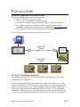
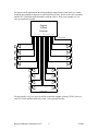
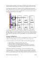
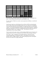
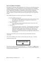
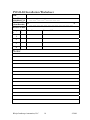
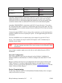
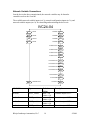
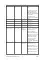
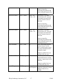
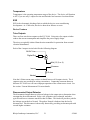
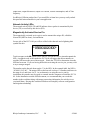
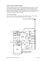
IVC24-04 User’s Manual
Version 1.0
© 2004 Bibaja Landscape Automation, LLC
INTRODUCTION
1
DOCUMENT ORGANIZATION
1
INSTALLATION
2
REQUIRED COMPONENTS FOR A BASIC SYSTEM
24-VOLT AC TRANSFORMER SELECTION
CHOOSING THE INSTALLATION LOCATION AND WIRING TOPOLOGY
CHOOSING THE RIGHT WIRE
DEVICE INSTALLATION WORKSHEET
DEVICE WALL MOUNTING
VALVE BOX INSTALLATION
WIRING THE DEVICE
NETWORK CONFIGURATION
DEVICE COMMISSIONING
NETWORK VARIABLE CONNECTIONS
2
2
3
6
9
11
11
11
12
12
14
IVC24-04 DEVICE SPECIFICATION
20
ELECTRICAL SPECIFICATIONS AND OPERATING CONDITIONS
VSUPPLY
ISUPPLY
VOUT(1,2,3,4)
IOUT(COMBINED)
IMEASURED
IERROR
TEMPERATURE
ESD
DEVICE FEATURES
TRIAC OUTPUTS
DISCONNECTED OUTPUT DETECTOR
CURRENT MEASUREMENT
POWER SUPPLY AND POWER LED
MICROCONTROLLER WITH EMBEDDED POWER LINE COMMUNICATIONS
NETWORK ACTIVITY LEDS
MAGNETICALLY ACTIVATED SERVICE PIN
20
20
20
20
20
20
20
21
21
21
21
21
22
27
27
28
28
APPLICATION EXAMPLES
29
LAWN & GARDEN IRRIGATION SYSTEM WITH MASTER VALVE
REQUIRED COMPONENTS
SYSTEM LAYOUT AND WIRE SELECTION
29
29
31
Bibaja Landscape Automation, LLC
i
© 2004
SYSTEM SETUP AND OPERATION
USING THE IVC24-04 FOR GENERAL 24-VOLT AC DEVICES
CONTACTORS
RELAYS
AIR DUCT DAMPERS
DRIVING DC DEVICES
USING THE IVC24-04 OUTPUTS AS INPUTS
Bibaja Landscape Automation, LLC
ii
33
34
34
34
34
35
35
© 2004
INTRODUCTION
The IVC24-04 is a four-output device useful for remote control of automatic irrigation
valves, relays, contactors, and many other standard 24VAC devices. The versatile triacdriven outputs of the IVC24-04 are well suited for many different applications.
Embedded power line communications and a sealed IP65/NEMA4 enclosure provide
easy system expansion. No need to dig a trench and lay new wires out into the field.
Attach wires to the nearest 24VAC power and add new valves. The IVC24-04 may be
placed into the valve box with the valves.
Integrated output disconnect detection circuitry provides a way to detect when the outputs
have been disconnected. This feature may be used to sense contact closures as well,
making the output of the IVC24-04 function as an input.
This document will present important details regarding how to install the IVC24-04
device and how to select the proper power supply and wiring.
Pay close attention to the specified ratings for the IVC24-04 device. Do not exceed the
maximum ratings to guarantee years of reliable operation.
Detailed specifications are given for the operation of some of the internal circuitry within
the IVC24-04. These circuit details will show you how our device operates and possibly
inspire other ideas for applications using the IVC24-04 device.
We will also attempt to cover a few application ideas for the IVC24-04. Check our
website periodically for new application ideas and updates for the IVC24-04 product.
Document Organization
This document is organized into three major sections:
1) Installation –
Provides a detailed guide for 24VAC transformer selection, wiring topology,
and mounting of the IVC24-04. Also gives a brief guide to installing and
configuring the IVC24-04 using LonWorks network management tools.
2) Device Specification Specifies the voltage and current ratings for the device. Also provides an indepth overview of device operation. These details may be of interest to
people who wish to understand how the circuits operate in more detail.
3) Application Examples –
Application ideas for the IVC24-04 device.
Bibaja Landscape Automation, LLC
1
©2004
INSTALLATION
Required Components for a Basic System
The required components to build a basic system are:
• One IVC24-04 for every 4 zone valves
• One 24-volt AC transformer for supplying power
• One PLC240 to bridge communications across the 24-volt AC transformer
• One USB12-01 power line network interface for your computer or other
compatible LonWorks powerline interface (Available from www.engenuity.com)
• One computer to run the system, log data, and interface with the internet
Here is diagram showing an example system and connections:
House AC
Power
24-volt AC
Transformer
24-volt AC
Power
24-volt AC Transformer Selection
Selecting the right 24-volt AC transformer for your system depends on the system’s
maximum current requirement.
Consider a lawn & garden irrigation system with 10 zones and 1 master valve. This
system will require 3 IVC24-04 units. Two valves will be active at the same time: The
master valve and one zone valve. Typical irrigation valves consume less than 300ma
steady-state current with a maximum inrush current of 700ma. Valves are actuated
sequentially. Therefore only one valve will consume the inrush current, while all other
active valves will consume the steady-state current. Each IVC24-04 device consumes a
Bibaja Landscape Automation, LLC
2
©2004
maximum of 100ma. The rating of the transformer will be the sum of these currents
calculated as follows:
1 master valve steady-state
1 zone valve inrush
3 IVC24-04 @ 100ma
Total
= 300ma
= 700ma
= 300ma
= 1300ma required current
VA Requirement (V*A)
= 24V * 1.3A
= 31.2VA minimum
24VAC transformers of various VA ratings are available online. Here is a short list of
places online where you can order wall plug and wire lead transformers, sorted by
increasing VA ratings:
Vendor Website
Part #
www.digikey.com
MT7116-ND
www.jameco.com
www.jameco.com
VA
Cost
(Estimated)
19.9
$13.05
10102
176356
24
30
$7.95
$10.49
www.smarthome.com
3061
40
$14.99
www.mouser.com
P-8663
96
$24.24
www.mouser.com
P-8665
192
$37.00
www.jameco.com
221410
288
$41.95
Features
Wall plug, screw
terminals
Wall plug, 3.1mm jack
Wall plug, 2.1mm jack
Wall plug, screw
terminals
Transformer, wire
leads
Transformer, wire
leads
Transformer, lugs
Note wire lead transformers are recommended only for those comfortable dealing with
electrical wiring. Wall plug transformers are much more convenient and plug into any
available AC outlet.
Choosing the Installation Location and Wiring Topology
The IVC24-04 enclosure is NEMA4/IP65 rated, so it may be located outdoors or indoors.
The choice of installation location will be determined by the choice of wiring topology.
For retrofit applications of simple 4-zone irrigation controllers, choosing the location is
simple: Put the IVC24-04 in the same location where the old controller was and use the
existing wiring. In some cases, the AC transformer from your old controller may work
to supply the IVC24-04 power as well. You will also need to bridge the power line
communication across the 24VAC transformer using the PLC240 device from Bibaja.
Without the PLC240, the USB12-01 will not be able to communicate with the IVC24-04.
Bibaja Landscape Automation, LLC
3
©2004
For larger retrofit applications involving multiple zones all star-wired back to a central
location, the existing wiring may be reused to bring 24VAC power to the valve locations
and the IVC24-04 units placed outdoors with the valves. Here is an example of a 16zone system before retrofit:
Original
16-Zone
Controller
1 2 3 4 5 6 7 8 9 10 11 12 13 14 15 16 C
COMMON WIRE
1
16
2
15
3
14
4
13
5
12
6
11
7
10
8
9
COMMON WIRE
For the retrofit, every two wires would be connected together to bring 24VAC power to
each IVC24-04 installed with each of the 4 valve groups like this:
Bibaja Landscape Automation, LLC
4
©2004
NEUTRAL
24
VAC
AC
LINE
PLC240
1 2 3
4 5 6 7 8 9 10 11 12 13 14 15 16 C
COMMON WIRE
NOT USED
1
16
2
15
IVC24-04
IVC24-04
C
3
C
14
4
13
5
12
6
11
IVC24-04
7
IVC24-04
C
C
8
10
9
The original valve control wires now carry 24VAC power and control signals to each
IVC24-04. Pairing every two wires insures adequate current and voltage for each IVC2404 and provides a little extra for system expansion. The original common is cut at each
valve group so only 4 valves are on each common (indicated by dashed lines in diagram).
This new 4-valve common is wired to the IVC24-04 corresponding to the valve group.
New controllers may be quickly added in the field by chaining a pair of wires from the
closest 24VAC power feed to the new valve group.
New installations may choose a star or bus topology for the wiring.
For star topology wiring, all of the IVC24-04 devices would be mounted in one location,
such as a garage or utility building wall, with output wires pulled out to each valve group.
One disadvantage with this topology is the cost of the wire. Having long wires from the
IVC24-04 to the valves may cost more than the bus topology. Adding more zones is also
Bibaja Landscape Automation, LLC
5
©2004
difficult with the star topology. New output wires must be routed and buried from the
central controller location to the valves resulting in more digging and more labor costs.
For bus topology wiring, the IVC24-04 devices may be installed in the field near the
valves. One pair of wires carrying 24VAC power would be bussed between each IVC2404. The IVC24-04 would be used to control the nearest 4 valves and could be located
inside one of the valve boxes. For example:
24VAC
VALVE BOX
VALVE BOX
VALVE BOX
VALVE BOX
VALVE BOX
VALVE BOX
VALVE BOX
IVC24-04
VALVE BOX
IVC24-04
One advantage of the bus topology is a reduction in wiring costs compared to the star
topology. Only two wires go out into the field to each valve group. Another advantage is
the ease of adding more devices. Extending your system is as easy as tapping the nearest
24VAC bus wire, connecting an IVC24-04, and adding valves to the nearest water feed
pipe.
Choosing The Right Wire
Choosing the right wire will insure reliable system operation. The right wire will supply
sufficient current and voltage for powering remote IVC24-04 devices and valves.
To choose the right wire, you will need to be able to answer the following questions:
1)
2)
3)
4)
What topology of wiring did you choose, bus or star?
What is the longest wire segment carrying 24VAC power?
How many devices (IVC24-04 and other) are on the longest wire segment?
How many outputs will be active at the same time and what is the maximum
current consumption of each output?
If the answer to questions 1 is star topology, you don’t really need to answer the
remaining questions. For distances less than 100 feet between the 24VAC transformer
and the IVC24-04 devices, 18AWG wire should be sufficient. 14AWG wire should be
used for current consumption greater than 3 amps or distances greater than 100 feet from
Bibaja Landscape Automation, LLC
6
©2004
the 24VAC transformer to the IVC24-04 devices. Typically 18AWG wire is used to
connect from the IVC24-04 to the remote valves. Installers may wish to consider running
a spare 14AWG wire pair carrying 24VAC out in the field. This will provide for easier
expansion in the future.
If the answer to question 1 is bus topology, you must provide estimates for the answers to
questions 2-4. Questions 3 and 4 are used to determine the maximum current
consumption on the longest wire segment. Consider a situation where you have 4
IVC24-04 devices on a 500ft wire segment. This segment has a pump control relay, a
fertigation valve, and zone valves. One and only one zone valve is active at a time. The
pump control relay, one zone valve, and the fertigation valve may all be active
simultaneously. Find the maximum current consumption numbers for each device
attached to the wire segment:
IVC24-04
Pump Relay
Fertigation Valve
Zone Valve
400ma (4 at 100ma each maximum)
4000ma (inrush)
600ma (typical)
700ma (inrush)
300ma (typical)
700ma (inrush)
300ma (typical)
Note the inrush current requirement of the pump relay is 4amps (4000ma). The wire
must be chosen to guarantee this current spike does not cause the voltage to dip beneath
18V or the pump relay may not activate. The maximum inrush current calculation is the
worst device plus the static current drawn by always-on devices like the IVC24-04:
Inrush = 100ma * 4 + 4000ma
Inrush = 4400ma
Since the pump is the first device activated, the current of the fertigation valve and zone
valve do not need to be included in the inrush calculation.
The typical operating current will be the maximum current for the 4 IVC24-04 devices,
the pump relay current, the fertigation valve, and one of the zone valves:
Typical = 100ma * 4 + 600ma + 300ma + 300ma
Typical = 1600ma
Use the larger of the two currents to determine the wire size and the transformer
requirement for your system. In this case, choose the inrush current of 4400ma. If you
plan to expand your system later, add some excess current to account for future devices
as well.
Use the following table to determine the wire gauge based on your longest wire segment
and the current consumption on that wire:
Maximum
Current (ma)
Longest Wire Segment (feet)
<100
<250
<500
<1000
Bibaja Landscape Automation, LLC
7
<1500
©2004
<500
<750
<1000
<1500
<2000
<2500
<3000
<4000
<5000
<7500
<10000
18AWG
18AWG
18AWG
18AWG
18AWG
18AWG
18AWG
14AWG
14AWG
12AWG
10AWG
18AWG
18AWG
18AWG
14AWG
14AWG
14AWG
12AWG
12AWG
10AWG
8AWG
8AWG
18AWG
14AWG
14AWG
12AWG
12AWG
10AWG
10AWG
8AWG
8AWG
14AWG
12AWG
12AWG
10AWG
8AWG
8AWG
12AWG
10AWG
10AWG
8AWG
The criteria for producing this gauge chart was what gauge of wire would produce less
than 3.5 volts of drop at the rated current over the distance in feet.
For our example of 500ft of wire with a current requirement of 4400ma, we would need
8AWG wire.
Note for this example you could eliminate the need for the 8AWG wire by placing the
IVC24-04 that controls the current hungry pump relay close to the 24VAC transformer.
This removes the pump relay from the longest wire segment and places it on an isolated
segment. This is better design practice and may result in wiring cost savings. Placing the
pump relay control close to the 24VAC transformer will allow the 500ft wire segment to
be reduced to 14AWG wire (<1000ma for 500ft). This topology is basically a
combination of the star and bus topology.
If your system requires more current, consider running multiple bus power feeds in a star
topology back to your 24VAC transformer and divide the current among the different
power feeds. Using a combination of star and bus topology wiring may be more
economical than using wire larger than 12AWG. Direct burial wire from 18AWG
through 12AWG is readily available. Also consider placing high current consumption
devices close to the 24VAC supply transformer.
Bibaja Landscape Automation, LLC
8
©2004
Device Installation Worksheet
Recording key information while installing the IVC24-04 devices will make the software
setup much simpler. To assist with this task, we have provided the device installation
worksheet on the following page. Print out copies of this worksheet fore each IVC24-04
device installed and record the device information to make software configuration
simpler. These worksheets will also serve as a record for the installer and the system
owner for what device outputs control what zones and where the devices are physically
located.
The worksheet has spaces to record several key pieces of information:
•
•
•
IVC24-04 NID (From Barcode)
o This is the 12-character unique ID found on the barcode on the side of the
IVC24-04 device. This ID is used to communicate with the device
through the power line network.
Output 1, 2, 3, and 4
o These rows are to record information about what is connected to each
output of the IVC24-04 device
Connected To
o Record what this output is connected to. This information is important for
configuring this output as a zone valve control, fertigation valve control,
master valve control, contact closure sense input, etc. If the device is
attached to a Cutler-Hammer contactor, for example, then record that
information as well since the contactor may require more inrush current to
actuate properly.
The note space should be used to record any other special information about the
connections.
The IVC24-04 NID barcode is found on a label on the side of the device. The label
should look similar to this:
*050001020300*
!
The NID is all numbers and letters between the two “* *” on the label. The ! symbol is
where to touch a magnet for activating the internal service switch to send the unique ID
over the network for installation.
Bibaja Landscape Automation, LLC
9
©2004
IVC24-04 Installation Worksheet
Job:
Install Date:
MM/DD/YYYY
IVC24-04 NID
(from Barcode)
Device Location
__ __ /__ __ /__ __ __ __
* __ __ __ __ __ __ __ __ __ __ __ __ *
Output
#
Zone Name:
Zone
#
Connected To:
1
2
3
4
Notes:
Bibaja Landscape Automation, LLC
10
©2004
Device Wall Mounting
The IVC24-04 provides two screw holes outside of the sealed area for wall mounting.
To attach the IVC24-04 to a wall:
•
•
•
•
•
•
•
•
•
•
•
•
Turn off power to IVC24-04 (if powered)
Loosen the black cable gland nut
Push and turn the 4 screw latches ¼ turn to release the lid
Carefully slide the lid of the IVC24-04 along the cable out of the way
Get a pencil
Hold the base of the IVC24-04 against the wall in the desired location and mark
the two hole locations with the pencil
Set the IVC24-04 aside and pre-drill the screw holes, if necessary
Feed screws into the base of the IVC24-04 unit, being careful not to drop the
screws onto the exposed electronics
Tighten the screws into the holes in the wall just until snug. DO NOT OVER
TIGHTEN MOUNTING SCREWS. Over tightening the screws could warp or
crack the case, compromising the sealed chamber.
Slide the lid back along the cable and onto the base.
Push and turn the 4 screw latches ¼ to secure the lid
Tighten the black cable gland nut
Valve Box Installation
The IVC24-04 devices are in sealed NEMA4/IP65 enclosures enabling installation
outdoors or in below ground valve boxes.
The IVC24-04 may be attached to the underside of the valve box lid following the
procedure for device wall mounting. The preferred method is to simply install the valve
in the bottom of the valve box as normal, attach the wires to the IVC24-04 using
waterproof connections, and lay the IVC24-04 in the valve box resting on top of the valve
assembly. The IVC24-04 comes with about 2 feet of cable, so it makes it easy to lift the
IVC24-04 out of the way if you need to access the valve or replace the valve solenoid.
Wiring the Device
Outdoor connections should use water resistant connections such as wire nuts with grease
caps. Indoor connections may be made using wire nuts, or by crimping quick disconnect
or screw terminal connectors onto the bare wires.
The wires of the IVC24-04 are color coded as indicated on the lid of the device:
24VAC POWER
OUTPUT 1
OUTPUT 2
LINE
NEUTRAL
SUPPLY
COMMON
SUPPLY
Bibaja Landscape Automation, LLC
BROWN
BLUE
ORANGE
YELLOW
11
©2004
OUTPUT 3
OUTPUT 4
COMMON
SUPPLY
COMMON
SUPPLY
COMMON
GRAY
VIOLET
GREEN
RED
BLACK
Attach the LINE/NEUTRAL connections to the 24VAC power wires. Try to keep the
LINE and NEUTRAL connections consistent between devices in the field. Keeping
LINE and NEUTRAL consistent throughout the installation will prevent damage in the
event that commons from two different IVC24-04 devices become shorted together.
Attach the LINE/NEUTRAL connections to the 24VAC power bus wires. Try to keep
the LINE and NEUTRAL connections consistent between devices in the field. This will
prevent damage in the event that commons from two different IVC24-04 devices become
shorted together.
Connect the output SUPPLY wires to valves, relays, contactors, or to the anode (positive
terminal) of diodes for devices requiring DC power. See the applications guide for more
information.
The four COMMON wires are common only to the outputs of a specific IVC24-04
device. One common wire may be used for all 4 outputs, or all 4 commons may be
attached, one per output.
!
Do not connect the commons of different IVC24-04 devices together. This
will cause improper operation of the current sensing circuit and possible failure
of the device.
Once wiring is complete, apply power to the devices and confirm the power LED is
illuminated.
Network Configuration
This section applies to users who are using tools such as Echelon’s LonMaker for
Windows and devices like Echelon’s i.Lon100 to configure and control the IVC24-04
devices.
Bibaja is working to develop our own configuration and control software based on the
USB12-01 device. If you have feedback about features you would like to see in this
software, feel free to provide this information by email to [email protected] with the
subject “Software Feature Request.”
Device Commissioning
For this step, either have the IVC24-04 Installation Worksheet handy or have a magnet
ready to activate the service pin.
Bibaja Landscape Automation, LLC
12
©2004
Choose to commission or install a new device using your chosen software package
(LonMaker for Windows, for example). When you get to the step for identifying the new
device, you have the option to either use service pin installation or manual installation.
For service pin installation, select “Service Pin” and proceed to the point where you are
prompted to press the service pin. Using a magnet, touch it to the + symbol on the side of
the device. Make certain the TX LED flashes at least once to confirm the service pin
message has been sent.
For manual installation, either type or scan the NID from the label from the side of the
device. If you used the IVC24-04 Installation Worksheet form, the NID should be
recorded on the third line “IVC24-04 NID”. Enter the 12 letters and numbers between
the two asterisks “**”.
Here is an example dialog from LonMaker for entering the IVC24-04 NID manually:
Once the device commissioning and installation process has been completed, you are
ready to proceed to making network variable connections and updating the device
configuration properties.
You may also look for “unconfigured” devices. The IVC24-04 device ship uncofigured
from the factory and may be installed this way if your installation tool supports it.
Bibaja Landscape Automation, LLC
13
©2004
Network Variable Connections
One the device has been commissioned, the network variables may be bound to
controllers such as the i.Lon100.
The available network variable inputs (nvi’s), network configuration inputs (nci’s), and
network variable outputs (nvo’s) for controlling and monitoring the device are:
IVC24-04
nvi
nviOut1
nvoState1
nvo
nvi
nviOut2
nvoState2
nvo
nvi
nviOut3
nvoState3
nvo
nvi
nviOut4
nvoState4
nvo
nvoDisconnect1
nvo
nvoDisconnect2
nvo
nvoDisconnect3
nvo
nvoDisconnect4
nvo
nvoOverCurrent1
nvo
nvoOverCurrent2
nvo
nvoOverCurrent3
nvo
nvoOverCurrent4
nvo
nvoCurrentRaw
nvo
nvoCurrentMil
nvo
nvoACFreq
nvo
nci
nciMaxRcvTime
NV/NC Name
Type
nviOut1
SNVT_switch
nviOut2
SNVT_switch
nviOut3
SNVT_switch
nviOut4
SNVT_switch
Bibaja Landscape Automation, LLC
Default
Value
state = off
value = 0.0
state = off
value = 0.0
state = off
value = 0.0
state = off
14
Description
Controls output OUT 1
Controls output OUT 2
Controls output OUT 3
Controls output OUT 4
©2004
nciMaxRcvTime
SCPTmaxRcvTi
me
value = 0.0
60.0 seconds
Output automatic shutoff
timer.
If no update is received on
nviOut1 through nviOut4
within the configured time
nciMaxRcvTime, the outputs
will be shutoff.
nvoState1
SNVT_switch
nvoState2
SNVT_switch
nvoState3
SNVT_switch
nvoState4
SNVT_switch
nvoDisconnect1
SNVT_switch
state = off
value = 0.0
state = off
value = 0.0
state = off
value = 0.0
state = off
value = 0.0
depends on
connection
This helps to prevent
flooding in case of controller
failure.
Feedback for the state of
output OUT 1
Feedback for the state of
output OUT 2
Feedback for the state of
output OUT 3
Feedback for the state of
output OUT 4
Feedback to monitor output
connection for OUT 1.
May also be used as a
contact closure input sensor.
Set to state = off, value = 0.0
when output is connected.
(When contact is closed)
nvoDisconnect2
SNVT_switch
depends on
connection
Set to state = on, value =
100.0 when output is
disconnected. (When contact
is open)
Feedback to monitor output
connection for OUT 2.
May also be used as a
contact closure input sensor.
Set to state = off, value = 0.0
when output is connected.
(When contact is closed)
Set to state = on, value =
Bibaja Landscape Automation, LLC
15
©2004
nvoDisconnect3
SNVT_switch
depends on
connection
100.0 when output is
disconnected. (When contact
is open)
Feedback to monitor output
connection for OUT 3.
May also be used as a
contact closure input sensor.
Set to state = off, value = 0.0
when output is connected.
(When contact is closed)
nvoDisconnect4
SNVT_switch
depends on
connection
Set to state = on, value =
100.0 when output is
disconnected. (When contact
is open)
Feedback to monitor output
connection for OUT 4.
May also be used as a
contact closure input sensor.
Set to state = off, value = 0.0
when output is connected.
(When contact is closed)
nvoOverCurrent1
nvoOverCurrent2
SNVT_switch
SNVT_switch
Bibaja Landscape Automation, LLC
state = off
value = 0.0
state = off
value = 0.0
16
Set to state = on, value =
100.0 when output is
disconnected. (When contact
is open)
Set to state = on, value =
100.0 when OUT 1 was the
last output activated before
an over current event was
detected.
State be cleared by
correcting the problem and
reactivating the output or by
resetting the device.
Set to state = on, value =
100.0 when OUT 2 was the
last output activated before
an over current event was
detected.
©2004
nvoOverCurrent3
nvoOverCurrent4
nvoCurrentRaw
nvoCurrentMil
nvoACFreq
SNVT_switch
SNVT_switch
SNVT_count
SNVT_amp_mil
SNVT_freq_hz
Bibaja Landscape Automation, LLC
state = off
value = 0.0
state = off
value = 0.0
State be cleared by
correcting the problem and
reactivating the output or by
resetting the device.
Set to state = on, value =
100.0 when OUT 3 was the
last output activated before
an over current event was
detected.
State be cleared by
correcting the problem and
reactivating the output or by
resetting the device.
Set to state = on, value =
100.0 when OUT 4 was the
last output activated before
an over current event was
detected.
State be cleared by
correcting the problem and
reactivating the output or by
resetting the device.
Raw count output from the
current sensor. See the
device specification section
for more information about
using this output.
0
Output is updated once per
second when non-zero.
RMS current in milliamps
converted from raw current
using a 5-segment piecewise
linear fit.
0
Output is updated once per
second when non-zero.
Depends on
Output from the line
line frequency frequency detector for status.
Reports either 50.0 or
60.0Hz.
17
©2004
nviOut1 – nviOut4
Connect nviOut1 through nviOut4 to the controller to turn outputs 1 through 4 on and off.
!
Do not bind nviOut[1-4] if the corresponding output[1-4] is used as an input to
sense a contact closure. This may result in an over current event and possibly
damage the contacts of the attached sensor.
nciMaxRcvTime
By default, nciMaxRcvTime is set to 60 seconds. This configuration parameter sets the
timeout from the automatic shutoff timer. When one of the network variable inputs
nviOut1-nviOut4 is updated, the timer will be initialized to this value and begin counting
down. When the timer reaches 0, the output will be turned off. If the network variable
input is updated before the timeout, the output will remain active.
This shutoff timer helps to prevent flooding in the event that the computer or controller
responsible for turning the output off fails. You may choose this timeout value based on
the maximum run time for the 4 attached zones or based on the amount of traffic on your
power line network.
If your controller is fairly simple and does not support “heartbeat” updates of network
variables, then the timeout value should be configured to the maximum run time of the
attached irrigation zones or devices.
nvoState1 - nvoState4
These four network variable outputs indicate the state of the device outputs 1-4. In a
polled system, these outputs may be monitored to determine if the output properly
activated.
These network variable outputs do not reflect the state of the corresponding network
input nviOut1-nviOut4. Instead they reflect the actual output status. After activating an
output using one of nviOut1-nviOut4, you must wait at least 10 AC Cycles to guarantee
the corresponding nvoState1-nvoState4 feedback has set. The maximum wait time is
200ms.
These status outputs may be bound to a datalogger or to lights on a status panel to
provide system status.
nvoDisconnect1-nvoDisconnect4
These four network variable outputs indicate whether an output has been disconnected. If
the output is disconnected, the network variable output will assume the state “on” and
value=100%. Connected outputs will assume the state “off” and value=”0%”.
These nvo’s may be used to sense contact closures if the outputs are used as inputs.
When the contact attached to an output is closed, the corresponding nvo will assume the
“off” state.
Bibaja Landscape Automation, LLC
18
©2004
When the corresponding network variable input nviOut1-4 is set to “on” and a non-zero
value, nvoDisconnect1-4 will assume the “off” and “0%” setting.
nvoOverCurrent1-nvoOverCurrent4
These four network variable outputs indicate which output caused the last over current
event. Over current events happen when the combined current draw of all outputs
exceeds about 1.3amps for 6 AC cycles in a row. The IVC24-04 is capable of providing
brief inrush currents of up to about 10amps to start devices like contactors.
These outputs latch state and may be reset in any of the following ways:
• Reset the IVC24-04 device (clears all status)
• Correct the problem and reactivate the output
• Cause an over current event on another output
If the combined current of all active outputs is greater than 1.2amps, consider moving
some active outputs to another IVC24-04.
If the current drawn from a single output exceeds 1.2amps, then it is recommend that an
intermediate relay be used to drive the external load. Relatively low cost relays are
available from Digikey (www.digikey.com) with 24VAC coils that consume around
130ma of current.
nvoCurrentMil and nvoCurrentRaw
Most users interested in datalogging the current will use network variable output
nvoCurrentMil. This output reflects the combined current consumption of all outputs in
milliamps from 340.0ma up through 3276.7ma. The accuracy of the current
measurement is +/- 6%. Current below 340.0ma will not register and will be reported as
0.0ma.
This sensor should be monitored to detect increasing current consumption over time.
Increasing current consumption may be an indicator that a valve solenoid or other
attached device is failing.
When the current consumption is non-zero and greater than 340ma, this output will be
updated at most once per second. With a large network of these devices, therefore, you
will quickly exceed the channel capacity if these connections are bound. Instead of
binding, it is recommended to periodically poll nvoCurrentMil on all devices with active
outputs.
For instructions on using nvoCurrentRaw, see the device specification in this manual.
nvoACFreq
This network variable output indicates the line frequency. It is updated when the device
is reset. The line frequency reported will be either 50Hz or 60Hz. If the line frequency is
100Hz, for some reason, it will therefore report 60Hz. 40Hz will report as 50Hz. This
output is not an indicator of the precise line frequency.
Bibaja Landscape Automation, LLC
19
©2004
IVC24-04 DEVICE SPECIFICATION
Electrical Specifications and Operating Conditions
Parameter
Vsupply
Isupply
Vout(1,2,3,4)
Min
18
--93% of
Vsupply
Iout (combined) --Imeasured
354
Ierror
-6
Temperature
-25
ESD
---
Typ
24
70
---
Max
28
100
---
Units
VAC (RMS)
ma (RMS)
VAC (RMS)
300
----25
---
1200
1300
+6
70
15
ma (RMS)
ma (RMS)
% error
C
kV
Vsupply
Vsupply is the supply voltage applied to the 24VAC power supply input. Note the
outputs require AC supply voltage for proper operation.
Isupply
Isupply is the current drawn, in milliamps RMS, from the 24VAC power supply input.
Vout(1,2,3,4)
Vout(1,2,3,4) is the output voltage when output 1, 2, 3, or 4 is activated. The figure 93%
of Vsupply assumes the supply has at least 1.3amps of current available.
Iout(combined)
Iout(combined) is the maximum output current allowed on all 4 outputs combined. If this
current limit is exceeded for more than 6 AC cycles in a row, all outputs will be turned
off and the last output turned on will be flagged as the one that caused the over current
condition.
Imeasured
Imeasured is the range of the current measurement circuit. Currents below 354 milliamps
RMS do not cross the voltage reference used to perform the current measurement. Above
1300 milliamps RMS, the over current detector will turn all outputs off.
Ierror
Ierror is the range of error for the piecewise linear fit used to calculate the network
variable output nvoCurrentMil. It is possible to achieve higher accuracy by trimming the
piecewise linear model or by using the network variable output nvoCurrentRaw to create
your own best-fit model for the current. See the “Current Measurement” section for more
information.
Bibaja Landscape Automation, LLC
20
©2004
Temperature
Temperature is the operating temperature range of the device. The device will function
to 85C if you use only 1 output at a time and limit the load current to less than 600ma.
ESD
ESD is the electrostatic discharge limit to which the devices were tested during
development. At 15 kilovolts, the device showed no failures or resets.
Device Features
Triac Outputs
There are four triac driven outputs on the IVC24-04. Using triacs for output switches
reduces the current consumption and simplifies the power supply design.
The triacs are optically isolated from the microcontroller for protection from external
electrical disturbances.
Each of the 4 output circuits looks like the following diagram:
24VAC Line
Digital Out
Opto
Out(1,2,3, or 4)
Common
Isense
0.5 ohm
Neutral
Note the 0.5ohm current sense resistor is shared between all 4 output circuits. The 4
common wires are provided for wiring convenience. Connecting commons between
different IVC24 devices will cause improper operation of the current sense circuit. See
the section “Current Measurement” for more details.
Disconnected Output Detector
The disconnected output detector relies on leakage in the output triac to determine when
an output has been disconnected. Relay coils, irrigation valve solenoids, and other
typical loads have a resistance much less than 1k ohms. This load will provide a path for
the leakage current back to Neutral. The path to Neutral is broken when the load is
disconnected. This disconnect is then easily detected by providing an alternate path with
a much higher resistance.
Bibaja Landscape Automation, LLC
21
©2004
The following circuit diagram shows the disconnect detect sense resistor connected to the
output:
24VAC Line
Digital Out
Opto
Disconnect
Detect
Out(1,2,3, or 4)
Common
Isense
0.5 ohm
Neutral
When the output is disconnected, a square wave (due to clamp diodes in the digital input
of the microcontroller) is present on the digital logic side of the disconnect detect sense
resistor. The microcontroller watches for this toggling input. If the input toggles for
more than 6 cycles in a row, the output will be marked as disconnected. At 50Hz,
therefore, it will take 6 AC line cycles, or 6 * 20ms = 120ms to detect a disconnected
output.
When driving a DC load (by adding a single diode, for example), connect the diode as
shown below for proper operation of the disconnected output detector:
24VAC Line
Digital Out
Opto
Disconnect
Detect
Out
LOAD
Common
Isense
0.5 ohm
Neutral
Connecting the diode with this orientation drives the load using the positive half cycle.
This allows the load to sink the leakage current on the positive half cycle, which allows
the disconnect detect circuit to sense the output is connected.
Current Measurement
Current measurement is accomplished by comparing the voltage across a sense resistor to
a reference voltage and then measuring the time the sense resistor voltage is above the
reference voltage.
Bibaja Landscape Automation, LLC
22
©2004
The circuit below shows the connection of the current measurement comparator to create
the Imeasure signal:
24VAC Line
Digital Out
Opto
Disconnect
Detect
Imeasure
+
Out(1,2,3, or 4)
Isense
Vref
Common
0.5 ohm
Neutral
The output Imeasure will only trigger when the signal Isense is larger than the voltage
reference Vref. Vref is set to approximately 0.25 volts with some hysteresis to reject
noise. This means the minimum trip current will be:
I=V/R
(Ohm’s Law)
I = 0.25 V / 0.5 ohm (Plug in Vref and current sensor resistor values)
I = 0.5 amps
(Minimum peak trip current)
I = 0.5 / sqrt(2)
(Divide by sqrt(2) to find RMS current)
I =~ 0.354 amps RMS (Minimum RMS trip current)
At around 354 milliamps, therefore, the current sensor will begin to measure current.
The Imeasure pulse from the comparator will be relatively short and will resemble the
following graph:
Bibaja Landscape Automation, LLC
23
©2004
Imeasure for 1 AC Cycle
Current (amps)
0.6
0.4
0.2
Current
Imeasure
0
-0.2
-0.4
0.
00
0
0.
00
3
0.
00
5
0.
00
8
0.
01
0
0.
01
3
0.
01
5
0.
01
7
0.
02
0
-0.6
Time (seconds)
Imeasure is an active low digital signal shown in yellow and is scaled & overlaid on top
of the current waveform. The peak of the current is around 0.5amps and is just enough to
trip the comparator.
Note the current sensor does not operate in the negative half cycle of the AC waveform.
Outputs are activated at the beginning of a positive AC half cycle. This guarantees the
minimum time between output activation and over current detection.
At 1.3amps RMS, the Imeasure pulse will almost cover the entire positive half cycle as
shown in the following graph:
Bibaja Landscape Automation, LLC
24
©2004
2.5
2
1.5
1
0.5
0
-0.5
-1
-1.5
-2
-2.5
Current
Imeasure
0.
00
0
0.
00
3
0.
00
5
0.
00
8
0.
01
0
0.
01
3
0.
01
5
0.
01
7
0.
02
0
Current (amps)
Imeasure for 1 AC Cycle
Time (seconds)
Two network variable outputs are provided from the current measurement circuit. The
first, named “nvoCurrentRaw”, is type SNVT_count and is the duration in 400ns ticks
that the signal Imeasure was low. For example, if the value of nvoCurrentRaw is 6500,
the duration of the Imeasure pulse was:
Duration = nvoCurrentRaw * 400ns
Duration = 6500 * 400 ns
Duration = 2600000 ns = 2.6 ms
Using nvoCurrentRaw, a function may be derived that more accurately converts the
Imeasure time duration into an RMS current value.
The second current measurement network variable output, named “nvoCurrentMil”, is
type SNVT_amp_mil. “nvoCurrentMil” uses a piecewise linear function to convert the
Imeasure pulse time into RMS current in milliamps. The following graph shows the
measured current vs. the piecewise linear current for an IVC24-04 unit across the current
measurement range:
Bibaja Landscape Automation, LLC
25
©2004
Measured Current vs. Piecewise Linear Fit
1.4
1.2
Current (amps)
1
0.8
DMM Current
nvoCurrentMil
0.6
0.4
0.2
0
0
5000
10000
15000
20000
nvoCurrentRaw (400ns counts)
The X-axis is the raw network variable output “nvoCurrentRaw”. The blue line is the
current as measured by a DMM. The yellow line is the network variable output
“nvoCurrentMil”.
The current measurement circuit serves two purposes:
1) To detect the over current condition and shut off outputs
2) To monitor increases in current consumption over time
The first function helps protect the IVC24-04 and the irrigation network in the event that
an output becomes shorted. When the current exceeds the limit for 6 AC cycles in a row
on one or a combination of outputs, all outputs will be turned off. The network variable
outputs “nvoOverCurrent1” through “nvoOverCurrent4” will indicate the last output
activated before the over-current condition was detected. When designing your system,
remember to take into account the number of outputs that will be activated
simultaneously and the current consumption of those outputs. The total current
consumption of all active outputs should not exceed 1.2amps for continuous operation.
The second function allows tracking trends in current consumption over time in valve
solenoids. Sometimes the current consumption of a solenoid will increase before failing.
Monitoring the current consumption of a solenoid while it is activated may give an early
warning allowing a solenoid to be replaced before it fails.
Bibaja Landscape Automation, LLC
26
©2004
Power Supply and Power LED
The power supply requires AC power, 50 or 60Hz, from 18 up to 28Vrms. Typical input
voltage is 24Vrms. The power supply is non-isolated, fuse protected, and has an MOV
for protection from voltage spikes and other momentary transients on the 24V power line.
It is a good idea to wire Line and Neutral consistently throughout the network, just in
case accidental connections are made between different IVC24-04 devices.
The Power LED is connected to the first DC stage of the power supply. This stage varies
from 25 to 40 volts DC proportional to input power. Brief high current drain, such as
packet transmissions, will cause fluctuations in the Power LED brightness.
Microcontroller With Embedded Power Line Communications
The microcontroller with embedded power line communications that makes this device
possible is the Echelon PL3120-E4T10. This 10MHz microcontroller packs 3 processors
and a powerful DSP based power line transceiver into a tiny 38-pin TSSOP package.
Communication on the power line network is two way, request and acknowledge. This
two way acknowledged communication provides much more robust communication
compared with X10. Sure, X10 has two way communication, but X10 still lacks robust
forward error correction, an alternate carrier frequency in case the primary one is
blocked, and the ability to perform remote diagnostics, remote application upgrades, and
the ability to transfer a variety of rich data types.
The PL3120-E4T10 microcontroller communicates using two carrier frequencies. The
primary carrier frequency is approximately 132kHz. The secondary is approximately
115kHz. The secondary frequency is only used if the first two attempts on the primary
carrier are not acknowledged.
Remote diagnostics are possible with the microcontroller. Application firmware keeps
statistics for number of packets received, CRC errors, missed messages, last error logged,
last cause of reset, and other useful information for remote diagnosis of problems.
The application firmware is stored in electrically erasable programmable memory, or
EEPROM for short. This memory may be rewritten 10,000 times. New application
firmware may be downloaded into the unit without removing it from the field. New
features, customer requested features, and bug fixes are all possible using this remote
upgrade capability.
Rich data types are available above and beyond simple on/off/dim controls. Soil
moisture, date & time, wind speed and direction, current consumption, and water flow
rate are all examples of data that may be transferred across the network and logged in the
central controller. The IVC24-04 uses these flexible data types to provide feedback for
Bibaja Landscape Automation, LLC
27
©2004
output state, output disconnect, output over current, current consumption, and AC line
frequency.
See Bibaja’s IOPoint product line if you would like to learn how you may easily embed
this powerful microcontroller in your own application.
Network Activity LEDs
The network activity LEDs TX and RX indicate when a packet is transmitted by this
device (TX) or received by this device (RX).
Magnetically Activated Service Pin
The magnetically activated service pin is used to transmit the unique ID, called the
Neuron ID (NID for short), for installation.
On one side of the IVC24-04 you will see a label with a barcode and a lightning bolt
symbol like this:
*050001020300*
!
Touch a magnet to the ! symbol on the label to activate the service pin and transmit the
NID. A magnetic reed switch inside the IVC24-04 will trigger the microcontroller to
send the NID across the power line network. Watch the TX LED to determine when the
NID has been sent. If you are having difficulties activating the service pin, you may wish
to try a stronger magnet.
The number on the barcode between the ** is the NID. In the example label, the NID is
“05 00 01 02 03 00”. The unique NID on the barcode is always 12 numbers and letters in
the range 0 to 9 and from A to F. As an alternative to using the service pin for
installation, this number may be typed or scanned into the computer to install the IVC2404. In the installation section of this document, we recommend that you record this
number in the worksheet along with output connection information for each device as
you install them. Having this worksheet filled out will simplify software configuration
and irrigation scheduling.
Bibaja Landscape Automation, LLC
28
©2004
APPLICATION EXAMPLES
This section gives several application examples utilizing the IVC24-04. If you have an
application idea you would like to submit, send an email documenting your application
idea to [email protected]. We will periodically publish new applications on our
website.
Lawn & Garden Irrigation System with Master Valve
Using Bibaja’s basic system components, it is possible to build a simple lawn & garden
irrigation system with the following features:
•
•
One master valve to shut off all water
11 irrigation zone valves
This application example with go step by step through the process of designing the
system for a home such as this one:
Layout and choice of sprinklers and drip emitters are beyond the scope of this example.
Work with a professional licensed irrigation contractor to design your system. Specify
Bibaja irrigation controls in advance so your contractor can plan the wiring and layout.
Required Components
The following components are required to build this system:
• Three (3) IVC24-04 devices
• One (1) PLC240 device
• One (1) USB12-01 device
Bibaja Landscape Automation, LLC
29
©2004
•
•
•
One (1) Computer
24-volt AC transformer
Wire for 24-volt AC power bus
The devices are connected together like this:
House AC
Power
24-volt AC
Transformer
24-volt AC
Power
The computer communicates with the network through Bibaja’s USB12-01 power line
network interface. For this system, the computer is always on and runs a scheduler
program to trigger zones in the irrigation system. The computer may also provide
remote access to your irrigation system. Email, paging or other notifications may be
enabled based on status feedback from the IVC24-04 devices to alert you to problems.
The sooner you know something has gone wrong, the sooner the problem may be
repaired saving your investment in landscape plants.
From the USB12-01, communication signals travel through the house AC power to the
PLC240. The 24-volt AC transformer will block power line communications. The
PLC240 is necessary to bridge communications across the 24-volt AC transformer from
the house AC power to the 24-volt AC irrigation power.
From the PLC240, power line communications travel to the IVC24-04 devices attached
to the 24-volt AC power. The computer may turn outputs on and off and check device
status to confirm everything is operating properly.
Bibaja Landscape Automation, LLC
30
©2004
System Layout and Wire Selection
For this example system, the contractor has decided the front yard requires 3 zones, the
back yard and sides require 4 zones, and the garden & orchard areas requires 4 zones.
One master valve will be installed to handle all zones. The valves will be placed in 3
groups. One group will be placed behind the shrubbery in the front of the home, another
group in the back yard shrubbery, and the garden & orchard valves will be placed in
valve boxes near where the zones are needed.
Choose Wiring Topology
First we need to choose the wiring topology and installation location. The following
picture shows where the contractor chose to place the 3 valve groups:
ORCHARD/GARDEN ZONES
BACKYARD/SIDE ZONES
FRONT YARD ZONES
MASTER VALVE
Bibaja Landscape Automation, LLC
31
©2004
Based on the contractor’s choices for valve locations, the simplest topology will be bus
topology for the wire. Bury the wire along the water main line for the irrigation system.
The water main line is the thick black line connecting the checker-patterned valve
location markers. One IVC24-04 device will be located at each valve group. The total
distance for the 24VAC bus wire will be around 150 feet.
The 24VAC transformer and the PLC240 will be installed inside the garage on the wall
near the first valve group. If you live in a colder climate, the irrigation contractor may
choose to install a manual shutoff valve and a port for connecting a compressor to blow
out the water for winterizing your system.
Selecting the Wire
The wire for the 24-volt AC power should be selected according to the section “Choosing
The Right Wire”. There are 4 questions to be answered:
1)
2)
3)
4)
What topology of wiring did you choose, bus or star?
What is the longest wire segment carrying 24VAC power?
How many devices (IVC24-04 and other) are on the longest wire segment?
How many outputs will be active at the same time and what is the maximum
current consumption of each output?
For this system, the wiring topology is bus topology. The longest wire segment is about
150 feet. There are 3 IVC24-04 devices on the longest wire segment. Finally, for
question 4, there are two outputs active at the same time: master valve and zone valve.
The maximum current consumption will be the steady state current for the master valve
and the inrush for one of the zone valves plus the current consumption of the 3 IVC24-04
units:
Master Valve
Zone Valve
3 IVC24-04 Devices
Total
300ma
700ma
300ma
1300ma
Maximum Steady-state Current
Inrush Current
Maximum Steady-state Current
Maximum required current
From the chart in the installation section, the example system falls in the column <250ft
and the row <1500ma making the wire selection 14AWG wire.
Installing the system
Now you have defined:
• The location for the 24VAC transformer and PLC240 (In the Garage)
• The location for the IVC24-04s (At each valve group)
• The wiring topology (Bus topology, 150 feet)
• The type of wire (14AWG, direct burial)
The irrigation contractor may now proceed with the installation. Make certain all outdoor
connections are water resistant.
Bibaja Landscape Automation, LLC
32
©2004
Make certain to use the worksheet to record the NIDs of each device and the attached
zone. This will make software setup much simpler.
System Setup and Operation
The software to run the system must now be configured. There are three basic tasks to be
completed:
1) Install and configure the IVC24-04 devices
2) Define the irrigation system and zones for the software
3) Define the irrigation schedules
Install and Configure IVC24-04 Devices
Depending on your software, you should have a way to easily add new devices. Refer to
your software manual on how to install a new device. You will need the NID from the
worksheets to communicate with and install the IVC24-04 devices.
Once the IVC24-04 devices are installed, either use the IVC24-04 device plug-in or a
device browser to configure the configuration property nciMaxRcvTime for your system.
This variable sets the automatic shutoff timers. If the computer loses communication
with the IVC24-04, this shutoff timer will turn off the outputs. For simplicity, simply
choose the maximum run time for the attached zones. If you have a drip zone that needs
to run for 30 minutes, then set the value for nciMaxRcvTime to 1800.
Define the Irrigation System and Zones
The example irrigation system consists of the master valve and the zone valves. The
controller for the system needs to know where the master valve and zone valves are
attached to be able to run the system properly.
If you are using software such as LonMaker for Windows, you will have to bind the
controller you use to guarantee the master valve is activated first, then the zone valves are
activated in sequence, and then the master valve is turned off. Heartbeats or multiple
updates must be configured to keep the master valve open for the duration of the
irrigation cycle.
From the worksheets, find which IVC24-04 outputs are connected to what devices in the
network. Bind the master valve to the control output that will activate for the duration of
each irrigation cycle. Then bind each zone valve to an output on your controller.
Define the Schedules
Once the connections are established, schedules must be defined to open the valves
regularly to meet the landscape’s water requirements. Make certain you know how
many minutes each zone requires. The irrigation contractor should be able to tell you
how long to run each zone in the system.
The sequence to run the system may look like the following:
Bibaja Landscape Automation, LLC
33
©2004
Start at 3:00am, Tuesday and Friday
Activate Master Valve
Activate Zone 1, 20 minutes
Activate Zone 2, 15 minutes
Activate Zone 5, 20 minutes
Activate Zone 6, 30 minutes
Deactivate Master Valve
Finish at 4:25am
Other sequences of zones may run on different days or may be programmed to run every
other day.
Using the IVC24-04 For General 24-volt AC Devices
The outputs of the IVC24-04 are useful for a variety of different devices other than
automatic irrigation valves. This application note will give a variety of different devices
and manufacturers and suggest some possible uses for them.
Contactors
Contactors are typically used to control large AC loads and devices with significantly
higher voltages. Large three phase pumps and roof-top air handler units are examples of
devices that may be controlled using a contactor.
The IVC24-04 may be used to control devices up to 1.2amps. Check the ratings on the
24VAC coil of the contactor you choose to see how much current it draws. It is possible
to control up to two Cutler Hammer 40amp contactors, for example.
Relays
Relays, like contactors, may be used to drive larger AC loads and higher voltages.
Typical uses for relays attached to an IVC24-04 are:
•
•
•
•
•
120VAC landscape lighting control
Irrigation pump control
12V low voltage lighting control
Greenhouse ventilation fan control
Heating cable controls
Potter & Brumfield makes a very economical panel mount double pole/double throw
relay with a contact rating of 30amps. The part number is T92S11A22-24 and is
available from www.digikey.com.
Air Duct Dampers
Air duct dampers, or air valves, may be used to turn off the conditioned air to a room in
your home that isn’t in use. Using the IVC24-04, you can save money by turning off the
air to unoccupied or unused rooms. This provides more heat or air conditioning to the
rooms that need it.
Bibaja Landscape Automation, LLC
34
©2004
These 24-volt activated dampers are part number 3080 available from SmartHome:
http://www.smarthome.com/3080.html
Driving DC Devices
Certain devices may require direct current or DC. Driving these devices is as simple as
adding a diode in series with the output terminal of the IVC24-04. This will provide halfwave rectified DC voltage for driving a motor or other device attached to the output.
By attaching a full-wave bridge rectifier to the output, more energy may be applied to the
DC load. Attach the output and common to the ~ inputs of the bridge. Attach the +/outputs from the bridge to your device. Measure the output voltage from the rectifier to
be sure it is within the ratings of the device you are trying to drive.
Using the IVC24-04 Outputs as Inputs
It is possible to use the IVC24-04 disconnected output detector to turn the IVC24-04
outputs into inputs.
Certain device types with cold-contact outputs may be attached to the IVC24-04 outputs.
When the contacts are closed, the IVC24-04 will think that an output is attached. The
corresponding network variable output nvoDisconnect[1-4] will then change to the state
“off” with value = 0. When the contacts are open, the nvoDisconnect[1-4] network
variable will change to state “on” with value = 1.
The following are a few examples of device types that may be attached:
•
•
•
PIR Motion Detectors (example: Slimline PIR Detector from
www.smarthome.com)
Float Switches (example: LVK-10 switch from www.omega.com)
Trip wires to detect when someone walked through an area (when wire breaks)
Note: Do not activate an output that has one of these devices attached. The IVC24-04
will detect the over current condition after 6 AC cycles and automatically turn off.
However, it may do damage to the attached device.
Bibaja Landscape Automation, LLC
35
©2004