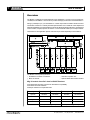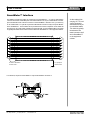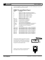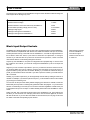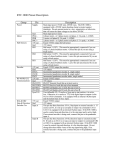
1
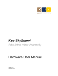
USER’S
Defining the Future in Motion Control
MANUAL
1
DINIO7
user ’s manual
Overview
The DINIO7 is a DIN-rail mounted peripheral for the SmartMotor™ versions 3 and 4 product lines.
Hereafter, the SmartMotor™ version 3 and 4 products will simply be referred to as the SmartMotor™.
Wiring Input/Output up to your SmartMotor™ is made simple with the DINIO7 breakout board.
The DINIO7 has slots for 7 Industry standard Opto Modules. This is a DIN rail mount adapter that
allows the SmartMotor™ to easily interface to popular I/O blocks like those produced by manufacturers
such as Gordos, Grayhill, Opto-22 and others. It can be used with either input or output modules.
These block I/O are application specific and must be purchased separately from the DINIO7.
The DINIO7 has four primary functions:
SmartMotor™ interface connections
Block I/O sockets
Animatics expansion bus
Optional differential encoder interface
Mfg. I/O module Cross Ref. chart for DINIO7 Breakout
All modules listed are 5VDC logic side for SmartMotor compatability
All modules have LED indication
All Output modules have replacable fuses
Mfg.
DC Input
DC Output
AC Input
AC Output
Opto-22
G4-IDC5
G4-ODC5
G4-IAC5
G4-OAC5A
Grahill
70G-IDC5
70G-ODC5A
70G-IAC5A
70G-OAC5A
Crydom
X4IDC5
X4ODC5
X4IAC5
X4OAC5
Gordos/Crouzet
C4-IDC5
C4-ODC5
C4-IAC5
C4-OAC5
(3-32VDC high side)
Fax: (408) 748 8725
(120VAC high side )
Tel: (408) 748 8721
www.animatics.com
DINIO7
user ’s manual
2
SmartMotor™ Interface
The DINIO7 provides two means of connecting to the SmartMotor™ – a 15 pin D subminiature
connector and a bank of standard pitch screw terminal blocks. The 15 pin D subminiature connector
pinout is identical to that of the I/O connector on the SmartMotor™ D series. Thus, you need only
to use a male-male 1-to-1 pinned 15 pinned D subminiature connector to fully hook up the DINIO7
to the SmartMotor™. These cables can be purchased from various companies. As the cable will
be carrying 5V TTL level signals, Animatics recommends that you use shielded cables. The shield
is typically terminated to the metal connector shell at the SmartMotor™ or the equipment cabinet.
1
9
2
10
3
11
4
12
5
13
6
14
7
15
8
1
9
2
10
3
11
4
12
5
13
6
14
7
15
8
DB15
Tie shield to SmartMotor
Connector shell ...
... or to equipment
cabinet chassis.
For reference, the pinout of the DINIO7’s 15 pin D subminiature connector is
8
15
Fax: (408) 748 8725
Tel: (408) 748 8721
1
9
www.animatics.com
As the cable will be
carrying 5V TTL level
signals, Animatics
recommends that you
use shielded cables.
The shield is typically
terminated to the
metal connector shell
at the SmartMotor™
or the equipment
cabinet.
3
DINIO7
user ’s manual
The second SmartMotor™ interface on the DINIO7 is the bank of standard pitch screw terminal
blocks. From right to left, these connections are:
DINIO7 Terminal Block Pinout
Signal
Description
A
B
C
D
E
F
G
ENC A OUT
ENC B OUT
RS232 TXD
RS232 RXD
+5V
S16 GND
PWR GND
PWR
NC
ENC A+ OUT
ENC A- OUT
ENC B+ OUT
ENC B- OUT
ENC A+ IN
ENC A- IN
ENC B+ IN
ENC B- IN
Digital input or output A / Encoder input A / Step input
Digital input or output B / Encoder input B / Direction input
Digital input or output C / Positive Limit input
Digital input or output D / Negative Limit input
Digital input or output E / RS-485 + / AniLink
Digital input or output F / RS-485 - / AniLink
Digital input or output G / Sync
Encoder A output from SmartMotor™
Encoder B output from SmartMotor™
RS-232 transmit from SmartMotor™
RS-232 receive to SmartMotor™
+5V, 210 mA source from SmartMotor™
Signal ground, tied to PWR GROUND within SmartMotor™
Power ground, tied to GROUND within SmartMotor™
20 to 48VDC input power to SmartMotor™
No connection
Optional differential encoder A+ output from SmartMotor™
Optional differential encoder A- output from SmartMotor™
Optional differential encoder B+ output from SmartMotor™
Optional differential encoder B- output from SmartMotor™
Optional differential encoder A+ input from SmartMotor™
Optional differential encoder A- input from SmartMotor™
Optional differential encoder B+ input from SmartMotor™
Optional differential encoder B- input from SmartMotor™
When all of the connections on the 15 pin I/O connector
are carried back to the SmartMotor™, the user has
direct access to the AniLink and channel 0 RS-232 port
from the DINIO7. Serial communication is accessible
through the connector labeled “RS-232”:
Similarly, the AniLink network is accessible through the
RJ-6 modular connector. Its pinout is given here:
Fax: (408) 748 8725
Tel: (408) 748 8721
www.animatics.com
DINIO7
user ’s manual
4
The ratings for the interface to the SmartMotors are given below. Absolute maximum ratings are
levels beyond which damage may occur.
Absolute maximum voltage:
5.5VDC
Absolute minimum voltage:
-0.3VDC
Absolute maximum current sourced/sunk by SmartMotor™:
30 mA
Recommended operating voltage (source or sink):
4.75-5.25VDC
Valid logical high signal:
2.0VDC
Valid logical low signal to SmartMotor™:
0.4VDC
Valid logical low signal from SmartMotor™:
0.8VDC
Block Input/Output Sockets
The DINIO7 has 7 block I/O sockets, one for each of the 7 general purpose I/O on the SmartMotor™.
These sockets are compatible with both 24VDC and 110VAC I/O modules from Opto-22, Crouzet
and Grayhill. When issuing commands from the SmartMotor™, note that the logical interface to
the I/O block is active low. That is, a port value of 0 would turn an output block, on closing its
contacts. If you read the value of a port that is connected to an input block, a value of 0 would
mean that the there is current flowing through the I/O block.
At power up, the SmartMotor™ I/O ports are configured as an input pulled high. In order to close
the contacts on an I/O block, you must both configure the SmartMotor™ port as an output and
set it low.
Suppose you have a 24VDC output block in port A. If you want the I/O block contacts to close,
you must first define port A as an output by using the UAO command. You then set port A to a
logical low state by using the UA=0 command. Similarly, if you needed to activate the relay on
port B, you would use the UB=0 command. If you want to open the contacts, you would issue the
UB=1 command.
Similarly, if you had an input block, you would generally read its state by stuffing its value into a
variable. For example, if you had an input block in port C, you would stuff its value into the variable
g by issuing the command g=UCI.
You can also use the port value directly without assigning port value into a variable, but this has
limited utility and may lead to confusing timing interaction within the program - so you have been
warned. It is interesting to note that you can issue this command regardless of whether the port
is configured as an input or an output. For further details, please refer to the SmartMotor™ User’s
Guide.
Please note that, due to the multi-functional nature of the SmartMotor™ I/O, some features are
lost when you use I/O blocks. For example, ports E and F can be used as digital I/O, as well as
RS-485 and AniLink. If you use either the RS485 or AniLink functions, do not plug an I/O block
into either of the slots corresponding to ports E and F.
Fax: (408) 748 8725
Tel: (408) 748 8721
www.animatics.com
When issuing commands
from the SmartMotor™,
note that the logical
interface to the I/O block
is active low.
5
DINIO7
user ’s manual
Animatics Expansion Bus
The Animatics Expansion Bus provides a convenient way to connect several SmartMotors and
their DIN-rail mount expansion modules without using any additional cable. Every Animators DINrail mount expansion module has two expansion bus connectors for receiving signals from modules
on either end of it. The bus passes through the module without any direct connection to any
SmartMotor™ I/O or expansion module function. To make use of the bus, it has to be connected
to some SmartMotor™ I/O or expansion bus card through the jumpers.
For example, let us suppose that your machine has six SmartMotors and you have a DINIO7
connected to each. If you wanted to connect port A on SmartMotors #1 and #4 together, you do
not have to run a cable between the two motors. Instead, you would install the expansion bus
bridge and the jumpers marked User A on their respective DINIO7s.
The Expansion Bus also allows for certain specialized connections. Every Expansion Bus is
equipped with 7 auxiliary lines that allow you to connect the SmartMotor™ I/O in various ways.
The DINIO7 allows you to connect the SmartMotor™ I/O A, B and encoder outputs to auxiliary
connections on the Expansion Bus. This allows you to hook up SmartMotors in a mode follow
(gearing) configuration without using any cables.
Fax: (408) 748 8725
Tel: (408) 748 8721
www.animatics.com
DINIO7
user ’s manual
Specifically, to hook up two SmartMotors for mode follow, simply set the following jumper connections:
Master motor:
Motor ENC A to Bus AUX 1
Motor ENC B to Bus AUX 3
Slave motor:
Motor A to Bus AUX1
Motor B to Bus AUX3
A schematic of the Animatics expansion bus and the DINIO7 jumpers is shown below:
Optional Differential Encoder Interface
If your DINIO7 is equipped with the optional electronics to interface with differential encoder I/O,
these signals can be interface through the Animatics expansion bus, as well as the screw terminal
expansion bus. These signals are not isolated from the SmartMotor™, so the user is cautioned
to avoid ground loops.
Fax: (408) 748 8725
Tel: (408) 748 8721
www.animatics.com
6
7
DINIO7
user ’s manual
Application
The DINIO7 is intended to provide a convenient interface to 24VDC and 110VAC block I/O modules.
These block I/O modules come in four forms: DC input, DC output, AC input and AC output. The
diagrams below show the functional representation of an example of each.
SmartMotor +5V
I/O +
SmartMotor I/O Port
I/O SmartMotor Signal GND
Typical DC Input Module
SmartMotor +5V
I/O +
4
SmartMotor I/O Port
2
I/O SmartMotor Signal GND
Typical AC Input Module
I/O +
SmartMotor +5V
SmartMotor I/O Port
I/O SmartMotor Signal GND
Typical DC Output Module
SmartMotor +5V
I/O +
SmartMotor I/O Port
SmartMotor Signal GND
I/O Typical AC Output Module
These are given for reference only. Your specific I/O module may or may not function as shown
in these diagrams.
Fax: (408) 748 8725
Tel: (408) 748 8721
www.animatics.com
DINIO7
user ’s manual
The diagram below shows a typical interconnect to a combination of some PLC inputs and outputs,
sensors, and both 110VAC and 24V relays and I/O blocks.
Fax: (408) 748 8725
Tel: (408) 748 8721
www.animatics.com
8
9
DINIO7
user ’s manual
You control the I/O in the same way as if you were using the local SmartMotor™ I/O. For example,
suppose that, in our example, you want to engage relay #3 for 0.1 second. Noting that relay #3
is wired to SmartMotor™ Port D, you would need to set up port E as an output with default high,
and turn it on by commanding the output low:
UD=1
UDO
UD=0
WAIT=407
UD=1
‘Before establishing that port E is an output,
‘predefine it to be default high
‘Define port E as an output
‘Turn on relay by setting port E low
‘Delay 0.1 second
‘Turn relay off by setting port E high
To read an input, you can either stuff its value into a variable or read it directly. Suppose that you
wanted to read the ouput #1 from the PLC. Note that output #1 is connected to SmartMotor™ port B.
You would typically set up port B as an input and then assign the port value to a variable – let’s
say we use variable bb:
UBI
bb=UBI
‘Setup port B as an input
‘stuff the port value of B into the variable bb
You can also read the port directly. This is generally used only when you are using it in an evaluation
expression, such as IF and WHILE. For example, if want to do something if port A is low, the IF
statement would be:
IF UAI
.
.
.
ENDIF
A while statement would look like:
WHILE UAI
.
.
.
ENDIF
For further details about the IF and WHILE statements, please refer to the SmartMotor™ Users
Guide.
Fax: (408) 748 8725
Tel: (408) 748 8721
www.animatics.com