1
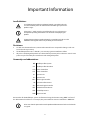
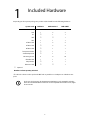
ReefKeeper Elite V2
Advanced Aquarium Controller
USER GUIDE
Copyright © 2010 Dynon Instruments DBA Digital Aquatics. All rights reserved, no part of this manual
may be reproduced, copied, transmitted, disseminated or stored in any storage medium, for any
purpose without the express written permission of Digital Aquatics. Digital Aquatics hereby grants
permission to download a single copy of this manual and of any revision to this manual onto a hard
drive or other electronic storage medium to be viewed for personal use, provided that such electronic
or printed copy of this manual or revision must contain the complete text of this copyright notice and
provided further that any unauthorized commercial distribution of this manual or any revision hereto is
strictly prohibited.
Information in this document is subject to change without notice. Digital Aquatics reserves the right
to change or improve its products and to make changes in the content without obligation to notify any
person or organization of such changes. Visit the Digital Aquatics website (www.DigitalAquatics.com)
for current updates and supplemental information concerning the use and operation of this and other
Digital Aquatics products.
1
Table of Contents
Important Information . . . . . . . . . . . . . . . . . . . . . . . . .4
1. Included Hardware . . . . . . . . . . . . . . . . . . . . . . . . . .5
2. Getting to Know the ReefKeeper Elite . . . . . . . . . . . . . . . . .6
2.1 Care and Maintenance . . . . . . . . . . . . . . . . . . . . . . . 6
2.2 Installation and Setup . . . . . . . . . . . . . . . . . . . . . . . 7
2.2.1 Startup . . . . . . . . . . . . . . . . . . . . . . . . . . . . 7
2.2.2 Connecting Modules . . . . . . . . . . . . . . . . . . . . . 7
2.2.3 Mounting . . . . . . . . . . . . . . . . . . . . . . . . . . 7
2.3 Updating Firmware . . . . . . . . . . . . . . . . . . . . . . . . . 7
2.4 How to Navigate the System Guide . . . . . . . . . . . . . . . . . 8
2.4.1 Instructions. . . . . . . . . . . . . . . . . . . . . . . . . . 8
2.4.2 Understanding the Interface . . . . . . . . . . . . . . . . . 9
2.4.3 General Notes . . . . . . . . . . . . . . . . . . . . . . . 10
3. Home Screen . . . . . . . . . . . . . . . . . . . . . . . . . . . . 11
3.1 The Home Screen . . . . . . . . . . . . . . . . . . . . . . . . . 11
3.1.1 Home Data . . . . . . . . . . . . . . . . . . . . . . . . . 11
3.1.2 Quick Data . . . . . . . . . . . . . . . . . . . . . . . . . 11
3.1.3 Icons . . . . . . . . . . . . . . . . . . . . . . . . . . . . 11
4. System Menu . . . . . . . . . . . . . . . . . . . . . . . . . . . . 13
4.1 Settings . . . . . . . . . . . . . . . . . . . . . . . . . . . . . 13
4.1.1 General “Gen”. . . . . . . . . . . . . . . . . . . . . . . . 13
4.1.2 System “Sys” . . . . . . . . . . . . . . . . . . . . . . . . 15
4.1.3 Display “Disp”. . . . . . . . . . . . . . . . . . . . . . . . 17
4.1.4 Timers (1 – 63) “Timr” . . . . . . . . . . . . . . . . . . . . 18
4.1.5 Alarms (1 – 63) “Alrm” . . . . . . . . . . . . . . . . . . . . 20
5. Inputs Menu . . . . . . . . . . . . . . . . . . . . . . . . . . . . 22
5.1 Input Screen . . . . . . . . . . . . . . . . . . . . . . . . . . . 22
5.2 Input Options . . . . . . . . . . . . . . . . . . . . . . . . . . 23
5.2.1 Calibrate . . . . . . . . . . . . . . . . . . . . . . . . . . 23
5.2.2 Enable Graph . . . . . . . . . . . . . . . . . . . . . . . . 24
5.2.3 Show Graph . . . . . . . . . . . . . . . . . . . . . . . . 24
6. Outputs Menu . . . . . . . . . . . . . . . . . . . . . . . . . . . 25
6.1 Output Screen . . . . . . . . . . . . . . . . . . . . . . . . . . 25
2
6.2 Output Options . . . . . . . . . . . . . . . . . . . . . . . . . 26
6.2.1 Channel Mode . . . . . . . . . . . . . . . . . . . . . . . 26
6.2.2 New Function . . . . . . . . . . . . . . . . . . . . . . . 26
6.2.3 Edit Function . . . . . . . . . . . . . . . . . . . . . . . . 26
6.2.4 Enable Graph . . . . . . . . . . . . . . . . . . . . . . . . 26
6.2.5 Show Graph . . . . . . . . . . . . . . . . . . . . . . . . 27
6.3 Setting up a Channel . . . . . . . . . . . . . . . . . . . . . . . 27
6.3.1 Pump . . . . . . . . . . . . . . . . . . . . . . . . . . . 27
6.3.2 Controller . . . . . . . . . . . . . . . . . . . . . . . . . 28
Controller Function Examples . . . . . . . . . . . . . . . . . . . 29
6.3.3 Multi-Timer . . . . . . . . . . . . . . . . . . . . . . . . . 31
6.3.4 Light . . . . . . . . . . . . . . . . . . . . . . . . . . . . 31
6.3.5 Advanced Light “Adv. Light” . . . . . . . . . . . . . . . . . 32
6.3.6 Lunar. . . . . . . . . . . . . . . . . . . . . . . . . . . . 32
6.3.7 Switch . . . . . . . . . . . . . . . . . . . . . . . . . . . 33
7. Data Logging and Graphing . . . . . . . . . . . . . . . . . . . . 34
7.1 Using Graphs . . . . . . . . . . . . . . . . . . . . . . . . . . . 34
8. Product Guide . . . . . . . . . . . . . . . . . . . . . . . . . . . 35
9. Troubleshooting . . . . . . . . . . . . . . . . . . . . . . . . . . 36
10. Notes . . . . . . . . . . . . . . . . . . . . . . . . . . . . . . . 37
3
Important Information
Icon Definitions
A exclamation point within an equilateral triangle is intended to alert the
user of a cautionary notice to which attention should be given prior to the
products usage.
A lowercase “i” within a circle is intended to alert the user to the presence
of important operating information in the literature accompanying the
product.
A jagged arrow within an equilateral triangle is intended to alert the user of a
hazardous warning that involves the possibility of electrical shock.
Disclaimers
•
•
•
As with most electronic devices, contact with water will cause unrepairable damage and is not
covered under any warranty.
The ReefKeeper Elite carries a limited 1 year warranty against manufacturer defect.
All probes sold by Digital Aquatics have a limited 90 day warranty unless otherwise stated. Some
probes may be covered by the manufacture and not Digital Aquatics.
Commonly used abbreviations
RKE
ReefKeeper Elite System
GC1
ReefKeeper Elite Headunit
PC4
Power Controller 4
PC1
Power Controller 1
SL1
System Lab 1
SL2
System Lab 2
MLC
Moon Light Controller
SID
System Interface Device
ALC
Advanced Light Controller
NET
Network Interface Device
SW5
Switch Expansion 5
HUB
Expansion Hub
Part numbers for the ReefKeeper systems are formatted using the character string “RKM-” in front of
the abbreviations listed above. For example, the part number for a Power Controller 4 is “RKM-PC4”.
Please note that the part numbers and a products abbreviation are both used within this
user guide.
4
Included Hardware
1
Depending on what system package was purchased, the kit will have the following hardware.
System Level
RKE Basic
RKE Standard
RKE w/NET
RKE Headunit (GC1)
1
1
1
PC4
1
2
2
1
1
SL1
NET
1
SID*
1
1
1
1ft Bus Cable
1
2
2
3ft Bus Cable
2
2
6ft Bus Cable
1
1
Temperature Probe
1
1
Switch Adapter Kit
1
1
Mounting Screws
4
8
10
6ft USB Cable
1
1
1
1
1
DA pH Probe
Ethernet Cable
1
Optional
Numbers indicate quantity included
* The SID is the device used to update the RKE and any modules via a USB port on a Windows computer.
At the time of this printing, the Programming Application is only compatible with Windows XP 32-bit and Windows Vista 32-bit. It is not compatible with 64-bit versions, Apple
OS or Linux OS.
5
Getting to Know the
ReefKeeper Elite
2
2.1 Care and Maintenance
The ReefKeeper Elite, as a system, is relatively maintenance free. Do not use water to clean any part of
the unit. Simply wiping down the surfaces of the modules should be all that’s needed.
If it’s found that there is excessive salt buildup or water splashing, the module affected should be
relocated. Not addressing this type of issue can result in a failure of that module and is not covered
under warranty.
Use a soft cloth such as that for eyeglasses to clean the face of the head unit to avoid scratches.
ReefKeeper Elite Headunit
RKM-SL1
Bus
Status
RKM-SL1
pH
Temp
Switch
ORP
RKM-PC4
1
1
2
3
4
Bus
Max Current Per Channel
2
1
1
2
3
4
Bus
Max Current Per Channel
2
RKM-PC4
Figure 2a: Example of a possible wiring configuration
6
2.2 Installation and Setup
2.2.1 Startup
When starting up the ReefKeeper Elite, make sure to not touch the key pad. The key pad must
remain untouched during boot so it can calibrate correctly.
This procedure is not required when using a V2 Headunit. These keys are mechanical and do not
require calibration.
2.2.2 Connecting Modules
While most customers may never approach 252 outlets or 63 pH probes, many will put together
systems beyond a basic setup. When adding modules to an RKE system, there are a number of
things to take into consideration.
Limitations of the ReefKeeper Elite
• 63 total modules
• 100’ total bus cable length. Some systems may be affected by electrical noise or environmental interference.
Modules for the ReefKeeper Elite system are plug and play and do not require the user to manually reconfigure the system like with other controllers. Also because of the type of bus we use,
modules can be hooked up in any order that a system requires within the stated limitations.
2.2.3 Mounting
Mounting the RKE can be done in several different ways depending on the needs and likes of the
customer.
ReefKeeper Elite head unit
There are several convenient options for mounting the RKE headunit.
1.
2.
3.
Side tabs with screws.
Slots on the back panel allow the head unit to mout by sliding it down over two screws. For
an increased cosmetic appearance the side mounting tabs can be broken off and removed.
Flush mounting. The head unit will fit nicely in a cabinet, wall or through any panel. The
side tabs on the head unit can be attached to the back side of the surface securing it to the
panel providing a clean, professional looking installation.
Two screws have been included with the RKE system to be used for mounting the
headunit.
Modules
Modules have been designed with convenient mounting tabs and include two mounting screws.
As with all electronic devices it is important to make sure to mount them as high as you can away
from water. Use drip loops for device and probe cords to prevent water from being introduced to
sensitive electronics. Take care to secure loose wires up out of the way to avoid potential hazards.
Make sure to review each module’s user guide for any special instructions that must be followed.
2.3 Updating Firmware
See the RKE Firmware Update Instructions for more information.
7
2.4 How to Navigate the System Guide
2.4.1 Instructions
This user guide has been written with every attempt to make the information and instructions as
easy to understand as possible. This section will explain some of the syntaxes and conventions
used to do this.
Square brackets([ ]) with a word or symbol inside indicate a key. The RKE has 11 keys as follows:
Menu [Menu]
Inputs [In]
Outputs [Out]
Back
[Back]
Function [FN]
Standby
[SB]
Up Arrow
[Up]
Down Arrow [Down]
Right Arrow [Right]
Left Arrow [Left]
Enter
[Enter]
Whenever an instruction calls for a key press the required key will be indicated as above.
Quotations(“ “) are used when the exact word, phrase or abbreviation is being used that the user
will see on the screen.
Words such as up, down, left and right will also be used without the square brackets when simple
directional instructions are being given. It is implied that the user will need to use the [Up],
[Down], [Left] and [Right] keys to follow these steps.
Saving
In most menus there is a “Save” selection at the bottom of the screen. All settings must be saved
to retain the changes and make them permanent.
Also note that when navigating a menu the user can press [FN] to quickly jump to the save option. Press [Enter] and the changes will be stored.
8
2.4.2 Understanding the Interface
Figure 2b: Front of the ReefKeeper Elite Head unit
11 Key Interface
The RKE has grown from the traditional three button interface that most controllers on the market use. Our new 11 key interface gives the user a more direct overall experience that allows for
faster and easier navigation.
Menu
Pressing the [Menu] key enters into the menu system where the user is able to manipulate most
of the settings of the ReefKeeper Elite system.
Inputs
Pressing the [In] key enters into the Inputs Menu where the user is able to see and configure the
input devices and probes that are currently connected to the ReefKeeper Elite system.
Outputs
Pressing the [Out] key enters into the Outputs Menu where the user is able to see and configure
the output channels/devices that are currently connected to the ReefKeeper Elite system.
Arrow Pad
The Arrow Pad is used for navigating through the system, changing views and manipulating settings.
Enter
The [Enter] key allows the user to confirm a selection when making changes.
Back
[Back] allows the user to back out of a selection without saving the changes. The [Back] key is also
used to back out or cancel certain actions such as Standby.
Function
The [FN] or function key is a dynamic key that allows for any number of functions to be assigned
depending on what screen the user is on.
9
Function Hot keys
1.
While in a settings screen, pressing [FN] will jump the highlighted selection to “Save”. This
is quite handy when working in long menus and the user wants to quickly make a single
change and save it.
2.
When a device is highlighted press [FN] to quickly view it’s graph. If the selected item is not
currently being graphed a message will appear.
3.
Pressing the [FN] key while an alarm is present will acknowledge the alarm.
Standby
While on the Home Screen, [SB] functions as quick access to either of the four standby modes.
The user can toggle through all of the standbys and then press [Enter] to select one. Before or
after a standby mode has been invoked, pressing the [Back] button will cancel the standby action
and return the user to the home screen.
The [SB] key is only active on the home screen.
2.4.3 General Notes
The following are general notes for the ReefKeeper Elite controller and intended to apply to
numerous entries in this user guide.
Device
When the word “Device” is used it refers to any probe, switch, or outlet. This allows a program to
use almost any item to control another.
The notation for a Device is in the following format:
##: Name
Value
## = Module number
Name = Device name such as “ORP”
Value = Current value of the device
Timeout
If the controller is left with no interaction from the user for 3 minutes it will time out and return to
the home screen.
Due to the specific process required during calibration, the timeout period will not
take affect when in the calibration menu.
Scrolling
Holding [Up] or [Down] will continuously scroll through values. While the key is being pressed,
the speed of the scroll will increase as the duration increases. This allows the user to more quickly
increment or decrement a value.
10
Home Screen
3
3.1 The Home Screen
The Home Screen is the primary screen that a user will see. It is the screen that all other screens time
out to after a period of inactivity. This screen is designed to give the user access to the most important
system data.
Date
Time
Home Data
Type A
Wavemaker
Sound
Battery
Key Lock
NET Communication
Wireless
Figure 3a: The Home Screen
Day / Night Mode
The date and time are displayed across the top of the home screen. There are two types of home
screen that the user can select from. See “Gen” settings for more information.
3.1.1 Home Data
Home Data is the large sized font on the home screen that displays the current value of the
selected probe. The Home Data is user selectable in the System settings and can display any port
that the user selects.
3.1.2 Quick Data
Quick Data is the smaller sized font on the home screen just below the Home Data. By pressing
[Up] or [Down] the user can quickly scroll through all available ports and their data.
3.1.3 Icons
The Home Screen has eight icons along the bottom of the page. These icons are intended to give
the user feedback on a variety of system parameters.
Wavemaker icon
Shows the current wavemaker mode of the system.
Day Mode icon
Shows the current state of the time system; day mode displays a sun and night mode displays an
animated moon (pausing at the current lunar phase.)
11
Sound icon
Displays the current audible setting.
Wireless icon
Intended for future use.
Battery icon
Intended for future use.
RKM-NET Communication icon
Shows network activity when a RKM-NET Network Interface Device is plugged into the RKE
system.
Key Lock icon
Displays the current status of the key lock.
12
System Menu
4
4.1 Settings
To enter into the settings menu, press the [Menu] key. A list will appear on the left side of the screen
with the menu options below. Use the [Up] and [Down] arrows to scroll through the selections, press
[Enter] when the menu item is highlighted.
During general navigation the [Right] and [Left] button can be used to quickly navigate through
menus and selections in the same way as [Enter] and [Back].
4.1.1 General “Gen”
Figure 4a: The General menu
Wave Maker A/B and C/D
This defines the wavemaker paired timers that set the opposing time period of an oscillation.
This is used in conjunction with power heads in a tank to create turbulent flow that simulates the
natural environment caused by wave action.
Setting wavemaker A’s duration and then B’s duration will set up a complimentary relationship
between the two cycles. Such that A is on when B is off and B is on when A is off.
They do not have to be of equal lengths; this allows the user to create a custom cycle.
The range for a wavemaker is from 11:59:00 to 00:00:01.
To have seconds resolution hours can not be set and if you want hour+ durations,
seconds can not be set. Either selection will go to 00 if the other is altered as shown
below.
Item
Description
Options
W.M. A
Wavemaker A Duration
HH:MM:00 or
00:MM:SS
W.M. B
Wavemaker B Duration
HH:MM:00 or
00:MM:SS
W.M. C
Wavemaker C Duration
HH:MM:00 or
00:MM:SS
13
Item
Description
Options
W.M. D
Wavemaker D Duration
HH:MM:00 or
00:MM:SS
HomeData
HomeData can be set to any channel, probe, or input, and will be displayed in large text on the
home screen. While in HomeData type A the quick data is not settable but is meant to be quickly
scrolled through with the [Up] and [Down] keys.
Item
Description
Options
Type
A: The default screen setting, HomeData Type
A, has the large home data and the smaller
quick data.
A/B
B: If HomeData Type B is selected the user can
select up to four probes, channels, or inputs
to view on the home screen at one time. Note
there is no quick data if this option is selected.
A/B1
Select this option for use in both HomeData
Type A and B.
All inputs and outputs
B2
Select this option for use with HomeData Type B
All inputs and outputs
B3
Select this option for use with HomeData Type B
All inputs and outputs
B4
Select this option for use with HomeData Type B
All inputs and outputs
Standby
Standby is a user settable mode that will stall/halt channels as defined by the user to perform
feedings, maintenance or any other tasks as needed.
Standby can be set from 00:01 to 59:59.
Item
Description
Options
SB 1
Standby 1 Duration
MM:SS
SB 2
Standby 2 Duration
MM:SS
SB 3
Standby 3 Duration
MM:SS
SB 4
Standby 4 Duration
MM:SS
Night Mode
Night Mode is a special timer that allows the user to establish a global time period that effects all
devices associated with it such as pumps, moonlights, and other devices the user would like to
have special attributes at night.
Item
Description
Options
On
Night Mode Start time
HH:MM
Off
Night Mode Stop time
HH:MM
Night mode is typically set such that it’s “on” or starts sometime in the evening and is “off ” or stops
sometime in the morning.
14
4.1.2 System “Sys”
Figure 4b: The System menu
Time/Date
This section is where the systems time and date are set. There is also a selection for 12 or 24 hour
clock modes.
Item
Description
Options
Time
Press [Left] and [Right] to highlight a field and
then use [Up] and [Down] to change a value.
HH:MM:SS
Clock
The “Clock” option allows the user to set either
12 or 24 hour clock modes for the system clock.
12 / 24
Date
Press [Left] and [Right] to highlight a field and
then use [Up] and [Down] to change a value.
MM/DD/YY
Sound
Here the user can turn off the sounds associated with key presses.
Item
Description
Options
Sound
This option only applies to the keypad sound.
ON / OFF
Units
This section is where the selection can be made for unit options. The RKE can display units in
either Fahrenheit or Celsius.
Item
Description
Options
Temp
Temperature Type
°C/°F
Lock Keys
The key pad of the RKE can be locked to help prevent unwanted access to the system. Enter the
Lock Keys menu in the Sys settings and select “On”. Once locked the RKE will exit to the Home
Screen and the unlock code must be entered to release the lock.
Item
Description
Options
Lock
Key Lock Toggle
ON / OFF
The unlock code: [Up], [Down], [Left], [Down]
15
Info
Item
Description
Options
Rev:
Displays the current firmware revision. Pressing
[Enter] with “Rev:” selected will update and
display the current value.
N/A
Detached
Displays the number of modules that have been
registered with the system but are not currently
connected.
N/A
Factory Defaults
Factory Defaults have been split into seperate sections. This allows certain areas and settings to
be reset while other remain intact. Running a complete Factory Reset will cause the RKE headunit
to re-register the modules connected to the system. This may cause new IDs to be assigned to
each module.
Figure 4c: The Factory Defaults
Factory resets will not affect the calibration data on the individual modules.
Item
Description
Options
Menus
This will reset the stored settings within the
General menu, System menu and Display menu.
YES / NO
Both Wavemaker settings and the system time
will not be reset using this option.
Functions
This will reset all of the stored settings for
Functions.
YES / NO
Timers
This will reset all of the stored settings for
Timers. This reset includes both of the Wavemaker settings.
YES / NO
Alarms
This will reset all of the stored settings for
Alarms
YES / NO
Logs
This will erase all stored logging data.
YES / NO
Reset All
This will completely reset all settings, programs
and logs. This should only be used as a last
resort in the event the ReefKeeper Elite settings
are unusable.
YES / NO
16
Factory Defaults and the RKM-NET
The RKM-NET relies on continuous communcation with the RKE headunit of the system. Many of
the configurations on the RKM-NET are built off the module list on the headunit. A factory reset
of the headunit will in most cases cause the module list to rearrange itself and thus the configurations on the RKM-NET are no longer valid. Becuase of this, a complete factory reset on the RKE
headunit will initiate a reset of both the Logging / RSS settings and the Custom Naming settings.
This includes a complete reset of the following:
•
•
•
•
Custom Module Names
Custom Port Names
All logged port data
All Logging / RSS slots
All other configurations and settings will remain untouched.
4.1.3 Display “Disp”
The Display menu is where the user can take advantage of all the display options of the RKE. Here
is where color, contrast, screen brightness and inversion can all be set.
Figure 4d: The Display menu
Color
There are 30 color options for the backlight of the display. Depending on the look of the tank,
fish room or just personal preference the RKE can be customized to the individual user.
Item
Description
Options
Color
Backlight Color
00 - 29
Contrast
The screen appearance can vary depending on mounting or viewing angle. Adjusting the contrast of the display can maximize the viewing experience.
Item
Description
Options
Contrast
Display Contrast
00 - 31
17
Brightness
Brightness is a setting that’s dependant on time of day. The display can be set to different brightness levels while in day mode and in night mode. The level will automatically change when the
system transitions from day to night and back again.
Item
Description
Options
Day
Brightness when not in Night Mode
00 - 10
Night
Brightness when in Night Mode
00 - 10
Item
Description
Options
Invert
Invert Display
ON / OFF
Invert Screen
4.1.4 Timers (1 – 63) “Timr”
There are 63 timers that can be set up by the user. Timers are used in conjunction with certain
programming options like the Multi-Timer and the Adv. Light function.
Figure 4e: The Timers menu
All the timers have the same layout and options.
Item
Description
Options
DoW
DoW is set by toggling the seven options to
either “-“or the leading letter of the day. “S - T W
T - -” would represent Sun, Tue, Wed, Thr to be
on and would represent Mon, Fri, Sat to be off .
Toggle “SMTWTFS”
Start At
This is the time for any of the selected days that
the timer will start.
HH:MM
Note: This time is applied to each day that’s
been selected for this one timer.
Time ON
Here is where the ON duration is set for the
timer event.
The range for an ON time is from 11:59:00 to
00:00:01.
18
HH:MM:00 or
00:MM:SS
Item
Description
Options
Time OFF
Here is where the OFF duration is set for the
timer event.
HH:MM:00 or
00:MM:SS
The range for an OFF time is from 11:59:00 to
00:00:01.
Repeat
The number of times a timer is repeated in a
single day can be set to 0 (meaning it will happen once) to 62 times in a single day.
0 - 62
If a timer is set to repeat any number of times
that will push the event past the next start time
for that timer, it will skip passed that START
point and miss the cycle for that occurrence.
Oscillate
If Oscillation is set to “Yes” the start time and repeat will be ignored and the cycle will continue
indefinitely.
YES / NO
To have seconds resolution, hours can not be set and if you want hour+ durations,
seconds can not be set. Either selection will go to 00 if the other is altered.
Example Settings for a Timer
The following settings will result in an error and the results will not be as expected. The On Duration and Off Duration will result in combined 8 hour cycle. When the cycle starts on Monday,
it will repeat this 8 hour cycle four times pushing it into Tuesday. Therefore the Tuesday cycle
will not start and the function will be stalled until Wednesday’s start time. This setup would
also affect Thursday in the same fashion.
DOW
-MTWTF-
Start At
10am
Time ON
04:00:00
Time OFF
04:00:00
Repeat
4
Oscillate
Off
19
4.1.5 Alarms (1 – 63) “Alrm”
There are 63 Alarms that can be set and used to initiate a change or an alert. All alarms can be
triggered by one of three criteria. While up to three criteria can be set, only one is needed. An
alarm does not need to be associated with a function to be useful. They can be used strictly as an
audible/visual alert to a set condition.
Figure 4f: The Alarms menu
To set up an Alarm, scroll to the desired alarm and press [Enter]. Then scroll through the options
setting up all the parameters as desired.
Once an alarm is set, it can be attached to any number of control functions. A single alarm can be
used as many times as desired.
Example
If Alarm #12 is triggered by a low water level and all the pumps in a system are to
shut off when alarm #12 is triggered, that one alarm can be associated with any and
all control functions where it’s needed.
Figure 4g: Example of Alarm usage
Device 1, Device 2 and Device 3
Item
Description
Options
Device
The Device selection allows any item in the
system to be selected as a trigger.
All inputs and outputs
Value
Indicates the value at which the trigger occurs.
Specific to each device
Trip
This selection indicates if the alarm is to trip
above or below the value.
Above
Below
20
Logic
This setting controls the form of logic used when more than one device has been set.
Item
Description
Options
Logic
The AND logic choice implements logical
conjunction. An alarm will be activated only if
all configured devices are triggered. If less than
the total number of configured devices are triggered, the alarm will not be activated.
AND
The OR logic choice implements logical disjunction. An alarm will be activated if any or all
configured devices are triggered. If none of the
configured devices are triggered, the alarm will
not be activated.
OR
Alert
Mode determines how the system will inform the user when the alarm is tripped. None of the
modes affect how an alarm is associated with a function and is strictly meant for notification.
Item
Description
Options
Alert
Alerts are set by toggling the three options to
either “-“or the leading letter for each option.
Toggle “FBE”
Flash is depicted by an “F” and will cause the
headunit’s display to flash a red backlight after
an alarm has been activated.
Beep is depicted by a “B” and will cause the
headunit to make an audible beep after an
alarm has been activated.
Email is depicted by an “E” and will cause email
notifications to be sent via the RKM-NET. This
function requires additional configurations on
the NET module as well.
21
Inputs Menu
5
This section contains information on how to access and configure inputs with the ReefKeeper Elite system. An Input is typically a probe or device that monitors a parameter in your system like temperature,
pH, and ORP.
5.1 Input Screen
To access the Input Screen, press the [In] key.
Figure 5a: Displays the available inputs for the selected device
Figure 5a above is composed of two windows. The left window shows any module in the system that
has an input. Once a module is highlighted, the right window shows its inputs and the current values
for those inputs.
While cycling through the connected modules the selected modules status LED will flash.
This will assist in identifying the selected module.
22
5.2 Input Options
To access the Input options navigate with the arrow keys to the input of interest. Press the [Enter] key
to view the input menu options for that item. This menu is used to calibrate and setup/view the graph
for the selected input.
The right window will display a list of options.
Figure 5b: The Input options
5.2.1 Calibrate
If calibration is not possible for the selected device this option will not be available.
Figure 5c: Example calibration screen
There are two types of calibrations that can be done depending on the probe, single point or
double point calibration.
Single Point Calibration (Temperature, ORP)
When doing a single point calibration, follow the steps below:
1.
2.
3.
Set the target data using the [up] and [down] arrows. In most calibrations where a reference
solution is used, adjusting the target data is not required.
Once the target data has been set, press [Enter] and place the probe in the calibration
solution.
Once the “Raw Data” value has stabilized, press [Enter] to save the calibration.
In some cases the “Raw Data” value will not completly settle on a single value. Also, the
“Raw Data” value is used internally and does not reflect a value in a probes input range.
23
Double Point Calibration (pH)
When doing a double point calibration, follow the steps below:
1.
2.
3.
4.
5.
6.
Set the target data using the [up] and [down] arrows. In most calibrations where a reference
solution is used, adjusting the target data is not required.
Once the target data has been set, press [Enter] and place the probe in the calibration
solution indicated by the Target value.
Once the “Raw Data” value has stabilized, select “Next” and press [Enter] to continue to the
next calibration point.
Rinse the probe in RO water.
Transition the probe to the second packet of calibration solution.
Repeat steps 1 through 3 for the second calibration point.
In some cases the “Raw Data” value will not completly settle on a single value. Also, the
“Raw Data” value is used internally and does not reflect a value in a probes input range.
Pressing [Back] will cancel any changes made during calibration. If the probe has more
than one calibration point, pressing [Back] will go back to the previous calibration point.
5.2.2 Enable Graph
Graph
Selects whether or not this port should be
logged.
YES / NO
If “No” is selected and saved all graphed history from that device is lost and can not be
retrieved.
5.2.3 Show Graph
Please see Chapter 7 for a more detailed explanation of the graphing.
24
6
Outputs Menu
This section contains information on how to access and configure outputs with the ReefKeeper Elite
system. An Output can be called a channel and typically will be associated with an outlet that will
control a device that is plugged into it.
6.1 Output Screen
To access the Output screen, press the [Out] key from the Home Screen
Figure 6a: The Outputs Screen
The left window shows any module in the system that has an output. The right window shows a module’s output once that module is highlighted.
While cycling through the connected modules the selected modules status LED will flash.
This will assist in identifying the highlighted module.
Figure 6b: The available outputs for the selected device
In Figure 6b an output device has been selected. The right window now shows a list of outputs associated with the current module and their current values.
6.2 Output Options
To access the Output options, navigate to the output of interest. Press the [Enter] key to view the output menu options for that item. This menu is used to configure, program, edit and graph the selected
output.
25
Figure 6c: The Output options
6.2.1 Channel Mode
There are three “modes” that a channel can be set to, Auto, On and Off. When any mode is selected other then Auto, the original function/program for that channel is not lost; it is ignored and
the override state is set.
Item
Description
Options
Mode
AUTO: Setting a channel to “Auto” puts the
channel under the control of the function assigned to it.
AUTO
ON
OFF
ON: Setting a channel to “On” will override that
channels function to an on state and it will not
follow the program.
OFF: Setting a channel to “Off ” will override that
channel to an off state and it will not follow the
program.
6.2.2 New Function
New Function allows the user to assign a new function to a channel. If the new function is not
saved the channel will retain its old function. New Function must also be used if the user is
changing the type of function that’s assigned to that channel.
6.2.3 Edit Function
Edit Function allows the user to edit the function that is currently assigned to that channel. If the
type of function assigned to the channel is being changed the user must use the NEW function
option.
6.2.4 Enable Graph
Graph
Selects whether or not this port should be
logged.
YES / NO
If “No” is selected and saved all graphed history from that device is lost and can not be
retrieved.
6.2.5 Show Graph
Please see Chapter 7 for a more detailed explanation of the graphing.
26
6.3 Setting up a Channel
The following is a list of options for programming an output. When dealing with timers and alarms be
sure to reference sections 4.1.4 and 4.1.5 if needed. Each Function has unique features that differentiate it from the others. While functions have names such as pump or light, they can be used however
the user would like or for any particular operation or feature desired. The function names are intended
to help assist the user in quickly setting up there ReefKeeper Elite system.
Function options
• Pump
• Controller
• Multi-Timer
• Light
• Advanced Light
• Lunar
• Switch
Setting up a channel using the key pad is intended to be as straight forward as possible.
To complete an entry, press the [Enter] key once the desired selection or modification is
made. As with most options the “Save” option must be selected once setup is complete.
Failure to save the settings and backing out of the menu will result in the loss of all
changes or settings made.
6.3.1 Pump
Pumps can be set with several options, all of which can be affected by entering a standby mode
or the triggering of an alarm.
Pump can also have a post standby delay. This delay will postpone the change in the state of the
pump when your system is taken out of standby. If a pump is set to turn off, the delay will hold it
for that duration beyond the triggering event. This can be extremely useful when coming out of
a standby mode used for feeding. A user can set the skimmer to come on after a delay so not to
over skim food from the system.
Figure 6d: The available outputs for the selected device
More programming examples can be found on our support forum at:
www.forum.digitalaquatics.com
27
Item
Description
Options
Pump
Active during wavemaker A
W.M. A
Active during wavemaker B
W.M. B
Active during wavemaker C
W.M. C
Active during wavemaker D
W.M. D
Sump/Skim: This option is active all the time
however standbys and alarms can be associated
with it to pause or delay its activity.
Sump/Skim
Night
A pump can be set to turn off in Night Mode.
This allows for the system to simulate the
calmer water in the evening hours.
ON/OFF
Delay
Defines the time delay after the function is
triggered.
HH:MM:00 or
00:MM:SS
Standby
Select whether this function should be affected
by Standby. This can be set by toggling the four
options to either “-“ or the Standby number.
Toggle “1234”
If SB
Operation to occur based on the standby option ON/OFF
selected.
Alarm
Select whether this function should be affected
by an alarm.
None,
Alarm 1 - 63
If Alarm
Operation to occur based on the alarm selected.
ON/OFF
6.3.2 Controller
The Controller function will change the state of an output based on the current state of an input
device. The user can select any of the available input or output devices such as a pH probe, temperature probe, or channel as an input device.
The controller function is often used for devices such as, Heaters, Chillers, Fans, Dosing pumps,
Auto top off (ATO) pumps and Calc reactors.
Item
Description
Options
Device
The Device selection allows any item in the
system to be selected as the trigger for the
output state.
All inputs and outputs
Target
The target value will depend on the probe
selected. If a temperature probe is selected the
user will select a temperature.
Specific to each device
Hysteresis
The hysteresis of the function, as used by the
ReefKeeper Elite, is a set window, equally divided above and below the set point. The user
sets the value of the hysteresis as so.
Specific to each device
More programming examples can be found on our support forum at:
www.forum.digitalaquatics.com
28
Item
Description
Options
ON when
This sets the condition for when the channel
should power the device plugged into it.
High / Low
A heater for example would be set to come on
“below” whereas a chiller or fan would be set to
come on “above”.
Standby
Select whether this function should be affected
by Standby. This can be set by toggling the four
options to either “-“ or the Standby number.
Toggle “1234”
If SB
Operation to occur based on the standby option ON/OFF
selected.
Alarm
Select whether this function should be affected
by an alarm.
None,
Alarm 1 - 63
If Alarm
Operation to occur based on the alarm selected.
ON/OFF
Controller Function Examples
These examples have been designed to give a breif description of the settings required to generate an intended result using the controller function.
Example Settings for a Heater
This example covers the basic function of turning on a heater when the temperature has
reached a low point.
Device
Temp (any temp probe can be used)
Set Point
78.0
Hysteresis
0.1
* 0.1 is a the smallest useable hysteresis that can be set for temp and
is suggested.
On When
Below
No alarms or standby are needed to operate a heater.
More programming examples can be found on our support forum at:
www.forum.digitalaquatics.com
29
Example Settings for a Fan or Chiller
This example covers the basic function of turning on a chiller when the temperature has
reached a high point.
Device
Temp (any temp probe can be used)
Set Point
78.0
Hysteresis
0.1
* 0.1 is a the smallest useable hysteresis that can be set for temp and is
suggested.
On When
Above
No alarms or standby are needed to operate a fan or chiller.
Example Settings for a pH Controller
This example covers raising pH and it should be noted that an SL1 is needed to monitor pH.
Device
pH
Set Point
8.25
Hysteresis
0.05
On When
Below
Example of Hysteresis
This example shows a temperature graph for a common setup utilizing the controller function
to turn on and off a heater. When using the Controller function for a heater, the function setting for “On When” should be set to “Below”. Hysteresis is abbreviated by H.
Off when greater than or equal to Set Point + H
Set Point + H
Temperature
Set Point
Set Point - H
On when less than or equal to Set Point - H
More programming examples can be found on our support forum at:
www.forum.digitalaquatics.com
30
6.3.3 Multi-Timer
The Multi-Timer allows the user to combine up to four timers to create a custom function.
If no Timers have been selected, the output of this function will be off.
Item
Description
Options
Timer
First timer
None
Timer 1 - 63
Timer
Second timer
None
Timer 1 - 63
Timer
Third timer
None
Timer 1 - 63
Timer
Fourth timer
None
Timer 1 - 63
Standby
Select whether this function should be affected
by Standby. This can be set by toggling the four
options to either “-“ or the Standby number.
Toggle “1234”
If SB
Operation to occur based on the standby option ON/OFF
selected.
Alarm
Select whether this function should be affected
by an alarm.
None,
Alarm 1 - 63
If Alarm
Operation to occur based on the alarm selected.
ON/OFF
6.3.4 Light
The light program allows the user to control different kinds of lighting with certain parameters
that are unique to that lighting such as Sure-on.
Sure-on is automatically active if Metal Halide (MH) is selected as the light type. This feature will
delay the power up of a MH in the event of a power outage or other power interruption for 15
minutes to give the bulb time to cool down so that it can refire.
Item
Description
Options
Light
Light Type
MH / Other
Time ON
Time when this light is to turn on.
HH:MM
Time OFF
Time when this light is to turn off.
HH:MM
Standby
Select whether this function should be affected
by Standby. This can be set by toggling the four
options to either “-“ or the Standby number.
Toggle “1234”
If SB
Operation to occur based on the standby option ON/OFF
selected.
Alarm
Select whether this function should be affected
by an alarm.
None,
Alarm 1 - 63
More programming examples can be found on our support forum at:
www.forum.digitalaquatics.com
31
Item
Description
Options
If Alarm
Operation to occur based on the alarm selected.
ON/OFF
6.3.5 Advanced Light “Adv. Light”
The Advanced Light Function can be used to program the MLC (Moon Light Controller,) or the
ALC (Advanced Light Controller.) Either module has the ability to control certain types of lighting
fixtures such as Aqua Illuminations LED lighting arrays, dimmable T5 ballast and our own Lunar
Pods. See the manuals for the listed modules for more information.
The information and features in this section are subject to updates and modifications as
the development process continues.
Item
Description
Options
Ramp
Sets the ramp duration in minutes.
0 - 250
Intensity
Light Intensity
0-100
Temp
Light Temperature in Thousands of Kelvin.
6K, 10K, 12K, 15K, 20K,
25K
Timer
First timer
None
Timer 1 - 63
Standby
Select whether this function should be affected
by Standby. This can be set by toggling the four
options to either “-“ or the Standby number.
Toggle “1234”
If SB
Operation to occur based on the standby option ON/OFF
selected.
Alarm
Select whether this function should be affected
by an alarm.
None,
Alarm 1 - 63
If Alarm
Operation to occur based on the alarm selected.
ON/OFF
6.3.6 Lunar
The Lunar option applies to the MLC and ALC. The Lunar function will set the output to follow the
nightly intensity of the moon.
This function has the option of being configured to any output on the system. Please
remember that only the MLC and ALC can vary the output intensity of a channel and
thus other types of outputs configured to this function may give unwanted results.
Intensity
Sets a scaling factor for the moonlight intensity.
This feature is most commonly used for users
that would like to reduce the overal intensity of
their moonlight pods.
0 - 100
Standby
Select whether this function should be affected
by Standby. This can be set by toggling the four
options to either “-“ or the Standby number.
Toggle “1234”
More programming examples can be found on our support forum at:
www.forum.digitalaquatics.com
32
If SB
Operation to occur based on the standby option ON/OFF
selected.
Alarm
Select whether this function should be affected
by an alarm.
None,
Alarm 1 - 63
If Alarm
Operation to occur based on the alarm selected.
ON/OFF
6.3.7 Switch
The Switch function allows a device to be controlled based on a standard boolean port. This
function will turn on the output channel once the device has triggered and will keep the channel
on until the configured Timer has finished.
The Switch function has the option of being configured using any port on the system.
Please remember that only boolean devices such as a switch or output channel will operate correctly. Configuring a Switch function using other types of types of inputs such
as Temp and pH may give unexpected results.
Device
The Device selection allows any item in the
system to be selected as the trigger for the
output state.
All inputs and outputs
ON when
This sets the condition for when the channel
should power the device plugged into it.
High / Low
Timer
Timer to be initiated once the device has triggered.
None
Timer 1 - 63
Standby
Select whether this function should be affected
by Standby. This can be set by toggling the four
options to either “-“ or the Standby number.
Toggle “1234”
If SB
Operation to occur based on the standby option ON/OFF
selected.
Alarm
Select whether this function should be affected
by an alarm.
None,
Alarm 1 - 63
If Alarm
Operation to occur based on the alarm selected.
ON/OFF
More programming examples can be found on our support forum at:
www.forum.digitalaquatics.com
33
Data Logging and
Graphing
7
7.1 Using Graphs
The ReefKeeper Elite has been designed to incorporate internal data logging of up to 32 unique devices. Any single data log can contain up to one week of data, stored at a 10 minute resolution.
Selecting “Show Graph” and pressing [Enter] will show the current graphed history of the selected port.
The Graph window was changed to give increased functionality in V1.10.
Figure 7a: Example graph of pH set to a range of 1-Day
1.
2.
3.
4.
5.
Pressing up and down will cycle through 1-Day and 5-Day mode respectivly.
Displays the port type.
Displays the current port value based on the location of the cursor.
Displays the current port average value. This is calculated from the entire logging buffer for the
port.
The cursor is used to find the value at different locations within the data.
If “No” is selected and saved, all graphed history from that device is lost.
34
8
Product Guide
This senction outlines the current Digital Aquatics product lineup.
System Modules
Part Number
Product Name
30-0014-001
RKM-PC4
30-0028-001
RKM-PC1
30-0015-001
RKM-SL1
30-0013-001
RKM-SL2
30-0018-001
RKM-MLC (White)
30-0018-002
RKM-MLC (Blue)
30-0023-001
RKM-ALC
30-0024-001
RKM-NET
30-0006-000
Expansion Socket
30-0026-001
RKM-SW5
30-0030-001
RKM-HUB
System Probes
Part Number
Product Name
30-0007-XXX
Digital Aquatics Temp Probe
30-0008-002
Digital Aquatics pH Probe Kit
30-0020-002
Digital Aquatics ORP Probe Kit
30-0031-000
Digital Aquatics Salinity Probe Kit
30-0008-000
Pinpoint pH Probe Kit
30-0020-000
Pinpoint ORP Kit
System Accessories
Part Number
Product Name
30-0019-000
MLC Pod (White)
30-0019-001
MLC Pod (Blue)
30-0008-001
pH Callibration Packets
30-0017-000
Switch Adapter Kit
30-0022-000
Bus Cables (3 x 1')
30-0022-001
Bus Cables (2 x 3')
30-0022-002
Bus Cables (2 x 6')
30-0022-003
Bus Cables (1 x 10')
30-0022-004
Bus Cables (1 x 20')
30-0022-005
Bus Cables (1 x 30')
30-0022-006
Bus Cables (1 x 50')
35
9
Troubleshooting
In order to offer our customers the highest level of support, Digital Aquatics has opened a public forum
dedicated to the support of our products. This forum allows us to offer the most up to date information and support of our products as well as building a knowledge base for the aquarium industry. Our
forum can be found at www.forum.digitalaquatics.com.
36
10
Notes
37
38
Digital Aquatics
19825 141st PL NE
Woodinville, WA 98072
www.DigitalAquatics.com
3/29/2010 - Rev 4