1
User's
Manual
Model GD402
Gas Density Meter
IM 11T3E1-01E
IM 11T3E1-01E
Yokogawa Electric Corporation
6th Edition (YK)
PREFACE
PREFACE
The Model GD402 gas density meter and Model GD40 detector not only provide continuous measurement of gas density, but also several other valuable parameters, including
specific gravity and molecular weight. The GD40 detector is designed for intrinsically safe
and flame-proof, explosion protected applications. It is designed to be virtually maintenance free for all accepted applications.
The Model GD402 is a rugged microprocessor-based converter designed in two versions to meet both general area and explosion-proof application requirements. In addition
to the display of several key data items, the converter also provides the choice of three different means for calibration: automatic; semi-automatic and one-touch manual operation.
Safety Precautions
This instrument is an IEC safety class 1 instrument ( provided with terminal for protective grounding).
The following general safety precautions must be observed during all phases of operation, service and repair of this instrument. If this instrument is used in a manner not specified in this manual, the protection provided by this instrument may be impaired. Also,
YOKOGAWA Electric Corporation assumes no liability for the customer's failure to comply with these requirements.
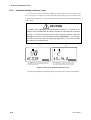
The following symbols are used on this instrument.
To avoid injury, death of personnel or damage to the instrument, the operator
must refer to an explanation in the User's Manual or Service Manual.
Danger, risk of electric shock.
Alternating current.
Direct current.
ON (power)
OFF (power)
Protective grounding terminal.
Function grounding terminal. This terminal should not be used as a "Protective
grounding terminals".
Make sure to comply with the following safety precautions. Not complying might result
in injury, death of personnel or damage to the instrument.
IM 11T3E1-01E
1
PREFACE
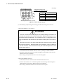
WARNING
●Power Supply
Ensure the power supply voltage matches instrument before turning ON the power.
●Protective grounding
Make sure to connect the protective grounding to prevent an electric shock before turning ON the power.
●Necessity of protective grounding
Never cut off the internal or external protective grounding wire or disconnect the wiring
of protective grounding terminal. Doing so poses a potential shock hazard.
●Defect of Protective Grounding and Fuse
Do not operate the instrument when protective grounding or fuse might be defective.
●Fuse
To prevent a fire, make sure to use fuses with specified standard (voltage, current, type).
Before replacing the fuses, turn off the power and disconnect the power source.
Do not use a different fuse or short-circuit the fuse holder.
●Do not Remove any Covers
There are some areas with high voltages. Do not remove any cover if the power supply
is connected. The cover should be removed by qualified personnel only.
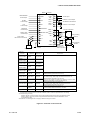
●Cross-Checking the Specifications
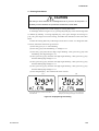
CAUTION
GD402 gas density meter is shipped after adjusting the both of detector and
converter in pairs. When installation, confirm wheter the serial number on both
of converter and detector are in pairs or not. If mismatched in pairs, converter is
to be out of order. When converter or detector supplied individually, enter the
detector constants, described on inside the lid of GD40, into converter so that
GD402 is going to be well.
In detail, please refer to Figure 5.30 on page 5-36, Figure 6.31 on page 6-35
or Figure 7.28 on page 7-32.
Upon delivery of the purchased product, unpack it carefully and make sure it is completely free from damage that may have occurred during transport. It must be shipped in
strict conformance to the purchaser's specifications. By way of precaution, confirm that
the equipment is the exact model you ordered. Also check that all accessory components are included. When confirming the specifications, refer to the model and suffix
codes indicated on the nameplate on the equipment. For a description of the model and
suffix codes, refer to Chapter 1, "Specifications."
2
IM 11T3E1-01E
PREFACE
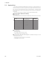
●Consideration of Operation Parameters
The GD402 meter operates with the same parameters set when it was delivered (default data) , when it is put into operation under these conditions.
Before starting measurement, check whether or not the default data meets your operating conditions. If necessary, re-set the parameters to suit your operating requirements.
To check the defaults, make use of the sheet, "Records of GD402's Operation Parameter
Settings," in the back of this manual. It is advisable that, if any of the operation parameter settings have been changed, the new data be noted in this record.
●Information Covered in This Manual
This manual covers all of the information for handling the GD402 converter and
GD40 detector, including instructions on installation, operation, setting of operation parameters, inspection and maintenance.
[Notational Conventions Specific to This Manual]
The following notational conventions apply to the representations of operation keys, information shown on the display, and information indicated on the product itself when they
are discussed specifically in the text of this manual.
●Operation Keys
Indicated with brackets [ ] as:
[YES] Key
●Information Shown on Display
Indicated with braces [ ] as:
[HOLD], meaning the status
[YES], meaning the indicator on an operation key
[CALIB], meaning a message
[205](lit) or [205] (blinking), meaning the data item shown along with its state
●Information Indicated on Product
Indicated with angle brackets < > as:<■>(lit) or <■
■ > (unlit), meaning the contact output indicator lamp along with its state
<MEASURE>mode, meaning the mode of measurement
●Information on the State of Blinking
Indicated in shaded typography as:
(blinking)
IM 11T3E1-01E
, in contrast to (lit)
3
PREFACE
r After-sales Warranty
d Do not modify the product.
d During the warranty period, for repair under warranty carry or send the product to the
local sales representative or service office. Yokogawa will replace or repair any
damaged parts and return the product to you.
d Before returning a product for repair under warranty, provide us with the model name
and serial number and a description of the problem. Any diagrams or data explaining
the problem would also be appreciated.
d If we replace the product with a new one, we won’t provide you with a repair report.
d Yokogawa warrants the product for the period stated in the pre-purchase quotation.
Yokogawa shall conduct defined warranty service based on its standard. When the
customer site is located outside of the service area, a fee for dispatching the maintenance engineer will be charged to the customer.
d In the following cases, customer will be charged repair fee regardless of warranty
period.
• Failure of components which are out of scope of warranty stated in instruction
manual.
• Failure caused by usage of software, hardware or auxiliary equipment, which
Yokogawa Electric did not supply.
• Failure due to improper or insufficient maintenance by user.
• Failure due to modification, misuse or outside-of-specifications operation which
Yokogawa does not authorize.
• Failure due to power supply (voltage, frequency) being outside specifications or
abnormal.
• Failure caused by any usage out of scope of recommended usage.
• Any damage from fire, earthquake, storms and floods, lightning, disturbances, riots,
warfare, radiation and other natural changes.
d Yokogawa does not warrant conformance with the specific application at the user site.
Yokogawa will not bear direct/indirect responsibility for damage due to a specific
application.
d Yokogawa Electric will not bear responsibility when the user configures the product
into systems or resells the product.
d Maintenance service and supplying repair parts will be covered for five years after the
production ends. For repair for this product, please contact the nearest sales office
described in this instruction manual.
4
IM 11T3E1-01E
Contents
Contents
PREFACE ................................................................................................................................ 1
◆ After-sales Warranty .......................................................................................................... 4
1. SPECIFICATIONS ..............................................................................................................1-1
1.1 Specifications of GD402 Gas Density Meter ............................................................................. 1-1
1.1.1 General Specifications ........................................................................................................ 1-1
1.1.2 GD40G, T, V, R Detector ................................................................................................... 1-5
1.1.3 GD402G,T, V, R Converter ................................................................................................ 1-6
1.2 Model Specifications .................................................................................................................. 1-8
1.2.1 Gas Density Converter ........................................................................................................ 1-8
1.2.2 Gas Density Detector .......................................................................................................... 1-8
1.2.3 Hardware for Connection with External Cables (For Explosion-Proof use) ...................... 1-9
1.2.4 Two-Core, Double-Shielded Cable ................................................................................... 1-10
1.2.5 Brain Terminal (Optional) ................................................................................................. 1-10
1.2.6 Pressure transmitter (Optional) .......................................................................................... 1-10
1.3 External Views and Dimensions ............................................................................................... 1-11
1.3.1 GD402G Converter (Non-Explosion-Proof) ..................................................................... 1-11
1.3.2 Pipe- and Wall-Mounting Hardware (Optional) ................................................................ 1-12
1.3.3 GD402T, V, R Converter (Explosion-proof) ..................................................................... 1-13
1.3.4 GD40 Detector ................................................................................................................... 1-14
1.3.5 Detector Unit ..................................................................................................................... 1-15
1.3.6 Surge protector: K9215LP ................................................................................................. 1-16
2. INSTALLATION, WIRING AND PIPING ............................................................................ 2-1
2.1 Installing the Detector ................................................................................................................ 2-2
2.1.1 Selecting the Location ........................................................................................................ 2-2
2.1.2 GD40T (FM Explosion-proof with Intrinsically Safe Approval) ....................................... 2-3
2.1.3 GD402T (FM Explosion-proof Approval) ......................................................................... 2-4
2.1.4 GD40V (CSA Explosion-proof with Intrinsically Safe Approval) .................................... 2-5
2.1.5 GD402V (CSA Explosion-proof Approval) ....................................................................... 2-6
2.1.6 Mounting the Detector ........................................................................................................ 2-7
2.2 Installing the Converter .............................................................................................................. 2-8
2.2.1 Selecting the Location ........................................................................................................ 2-8
2.2.2 Mounting the Converter ...................................................................................................... 2-9
2.3 Piping ......................................................................................................................................... 2-11
2.4 Wiring ........................................................................................................................................ 2-13
2.4.1 Wiring Procedure ............................................................................................................... 2-13
2.4.2 Cable Wired to Power Supply ........................................................................................... 2-17
2.4.3 Cables Wired to Outputs .................................................................................................... 2-18
2.4.4 Cables Wired to Contact I/Os ............................................................................................ 2-19
2.4.5 Cable Wired to GD40■
■ Detector ...................................................................................... 2-20
2.4.6 Cables Wired to the Ground .............................................................................................. 2-21
3. OPERATION .......................................................................................................................3-1
3.1 Preparation for Operation ........................................................................................................... 3-1
6th Edition : Sep. 2008(YK)
All rights Reserved Copyright © 1998, Yokogawa Electric Corporation
IM 11T3E1-01E
Contents
3.1.1 Inspecting Installation, Piping and Wiring Workmanship ................................................. 3-1
3.1.2 Supplying Power ................................................................................................................ 3-2
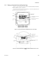
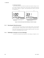
3.1.3 Display on Operation Panel and Operation Keys ............................................................... 3-3
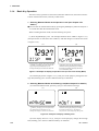
3.1.4 Basic Key Operation ........................................................................................................... 3-4
3.1.5 Checking the Setting Parameters ........................................................................................ 3-6
3.1.6 Calibrating the Analyzer for Correct Readings .................................................................. 3-6
3.1.7 Checking the Analyzer for Performance ............................................................................ 3-7
3.2 Normal Operation ....................................................................................................................... 3-8
3.2.1 Starting Operation ............................................................................................................... 3-8
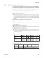
3.2.2 Corrective Actions in Case of Failure ................................................................................ 3-9
3.2.3 Inspection and Maintenance ............................................................................................... 3-9
3.3 Shutdown and Restart ................................................................................................................ 3-10
3.3.1 Measures for Shutdown ..................................................................................................... 3-10
3.3.2 Measures for Restarting ..................................................................................................... 3-10
4. FUNCTIONS .......................................................................................................................4-1
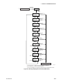
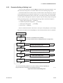
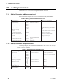
4.1 Summary of Setting Operations ................................................................................................. 4-1
4.1.1 Measurement, Operation, Setting and Service ................................................................... 4-1
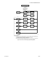
4.1.2 Key Operations ................................................................................................................... 4-2
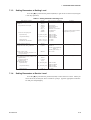
4.1.3 Points to Be Noted When Making Settings ........................................................................ 4-3
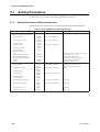
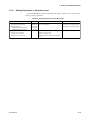
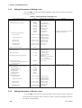
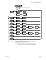
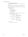
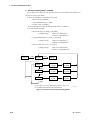
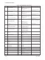
4.2 Setting Lists ............................................................................................................................... 4-4
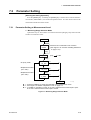
5. DENSITY / PARAMETER SETTING .................................................................................. 5-1
5.1 Setting Parameters ...................................................................................................................... 5-2
5.1.1 Setting Parameters at Measurement Level ......................................................................... 5-2
5.1.2 Setting Parameters at Operation Level ............................................................................... 5-3
5.1.3 Setting Parameters at Setting Level .................................................................................... 5-4
5.1.4 Setting Parameters at Service Level ................................................................................... 5-4
5.2 Parameter Setting ........................................................................................................................ 5-6
5.2.1 Parameter Setting at Operation Level ................................................................................. 5-6
5.2.2 Parameter Setting at Setting Level .................................................................................... 5-10
5.2.3 Parameter Setting at Service Level .................................................................................... 5-16
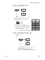
6. CALORIE / PARAMETER SETTING ................................................................................. 6-1
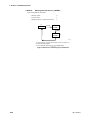
6.1 Setting Parameters ...................................................................................................................... 6-2
6.1.1 Setting Parameters at Measurement Level ......................................................................... 6-2
6.1.2 Setting Parameters at Operation Level ............................................................................... 6-3
6.1.3 Setting Parameters at Setting Level .................................................................................... 6-4
6.1.4 Setting Parameters at Service Level ................................................................................... 6-4
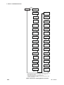
6.2 Parameter Setting ........................................................................................................................ 6-6
6.2.1 Parameter Setting at Operation Level ................................................................................. 6-6
6.2.2 Parameter Setting at Setting Level .................................................................................... 6-11
6.2.3 Parameter Setting at Service Level .................................................................................... 6-15
7. HYDROGEN PURITY SETTING ........................................................................................ 7-1
7.1 Setting Parameters ...................................................................................................................... 7-2
7.1.1 Setting Parameters at Measurement Level ......................................................................... 7-2
7.1.2 Setting Parameters at Operation Level ............................................................................... 7-2
7.1.3 Setting Parameters at Setting Level .................................................................................... 7-3
IM 11T3E1-01E
Contents
7.1.4 Setting Parameters at Service Level ................................................................................... 7-3
7.2 Parameter Setting ........................................................................................................................ 7-5
7.2.1 Parameter Setting at Measurement Level ........................................................................... 7-5
7.2.2 Parameter Setting at Operation Level ................................................................................. 7-8
7.2.3 Parameter Setting at Setting Level ..................................................................................... 7-9
7.2.4 Parameter Setting at Service Level .................................................................................... 7-13
8.DENSITY / CALIBRATION PROCEDURE .......................................................................... 8-1
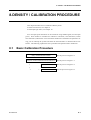
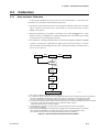
8.1 Basic Calibration Procedure ....................................................................................................... 8-1
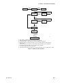
8.2 Preparation for Calibration ......................................................................................................... 8-2
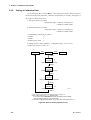
8.2.1 Setting Type of Calibration and Checking Valve Operation .............................................. 8-2
8.2.2 Setting of Calibration Data ................................................................................................. 8-4
8.3 Calibration .................................................................................................................................. 8-5
8.3.1 Semi-automatic Calibration ................................................................................................ 8-5
8.3.2 Manual Calibration ............................................................................................................. 8-6
8.3.3 Automatic Calibration ........................................................................................................ 8-7
9.CALORIE / CALIBRATION PROCEDURE ......................................................................... 9-1
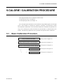
9.1 Basic Calibration Procedure ....................................................................................................... 9-1
9.2 Preparation for Calibration ......................................................................................................... 9-2
9.2.1 Setting Type of Calibration and Checking Valve Operation .............................................. 9-2
9.2.2 Setting Calibration Data ..................................................................................................... 9-4
9.3 Calibration .................................................................................................................................. 9-6
9.3.1 Semi-automatic Calibration ................................................................................................ 9-6
9.3.2 Manual Calibration ............................................................................................................. 9-7
9.3.3 Automatic Calibration ........................................................................................................ 9-9
10. HYDROGEN PURITY / CALIBRATION PROCEDURE .................................................. 10-1
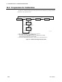
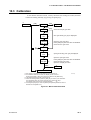
10.1 Basic Calibration Procedure .................................................................................................... 10-1
10.2 Preparation for Calibration ...................................................................................................... 10-2
10.3 Calibration ............................................................................................................................... 10-3
11. INSPECTION AND MAINTENANCE ............................................................................... 11-1
11.1 Routine Inspection and Maintenance ...................................................................................... 11-1
11.1.1 Checking Readings and Calibrating the Analyzer ........................................................... 11-1
11.1.2 Checking the Flowrate of Sample Gas ............................................................................ 11-1
11.1.3 Periodical Replacement of the Detector's O-rings ........................................................... 11-1
11.1.4 Replacing the Fuse ........................................................................................................... 11-2
11.1.5 Cleaning ........................................................................................................................... 11-2
11.2 Inspection in Case of Failure ................................................................................................... 11-3
11.2.1 Inspecting the Analyzer in an Alarm Status .................................................................... 11-3
11.2.2 Inspecting the Analyzer in a FAIL Status ....................................................................... 11-4
Customer Maintenance Parts List ......................................................................... CMPL 11T3E1-01E
Customer Maintenance Parts List ......................................................................... CMPL 11T3E1-02E
Customer Maintenance Parts List ......................................................................... CMPL 11T3E1-03E
Revusion Record ................................................................................................................... 1
IM 11T3E1-01E
1. SPECIFICATIONS
1. SPECIFICATIONS
1.1 Specifications of GD402 Gas Density Meter
The specifications of the Model GD402 gas density meter are as describedbelow.
Certificate is approved for model GD402G, GD40G.
1.1.1
General Specifications
1.1.1.1 System Components
(1) GD40G, T, V, R Detector:Rainproof for outdoor use (equivalent to IP65/
NEMA4X)
(see note under "1.1.2.2 Ambient conditions" on page1-5.)
Ambient Temperature :-10 to 60˚C
Ambient Humidity : 5 to 95%RH
GD40T :
FM Explosion-proof and Intrinsically safe Approval.
Explosion-proof for Class I, Division 1, Groups B, C and D;
Dust Ignition-proof for Class II, III, Division 1, Groups E, F and G
with Intrinsically Safe sensor for Class I, II, III, Division 1, Groups
B, C, D, E, F and G.
Enclosure : NEMA Type 4X
Temperature Code : T5
Electrical connection : 1/2NPT female
Process connection : 1/4NPT female
GD40V :
CSA Explosion-proof and Intrinsically safe Approval.
Explosion-proof for Class I, Division 1, Groups B, C and D;
Dust Ignition-proof for Class II, III, Division 1, Groups E, F and G
with Intrinsically Safe sensor for Class I, II, III, Division 1, Groups B,
C, D, E, F and G.
Enclosure : Type 4X
Temperature Code : T5
Electrical connection : 1/2NPT female
Process connection : 1/4NPT female
GD40R :
TIIS Explosion-proof and Intrinsically safe Approval.
Explosion-proof code : Exd [ia] IIB+H2T5
Temperature Code : T5
Electrical connection : G1/2 female
Process connection : Rc1/4 female
(2) GD402G, T, V, R Converter : Rainproof for outdoor use (equivalent to
IP65 / NEMA 4X)
Ambient Temperature : -10 to 55˚C
Ambient Humidity : 5 to 95%RH
IM 11T3E1-01E
1-1
1. SPECIFICATIONS
GD402G :
General purpose converter. (Non Explosion-proof)
Electrical connection : 21mm (0.9inch) in diameter. Pg13.5 cable
glands included
GD402T :
FM Explosion-proof Approval.
Explosion-proof for Class I, Division 1, Groups B, C and D;
Dust Ignition-proof for Class II, III, Division 1, Groups E, F and G.
Enclosure : NEMA Type 4X
Temperature Code : T6
Electrical connection : 1/2NPT female
GD402V :
CSA Explosion-proof Approval.
Explosion-proof for Class I, Division 1, Groups B, C and D;
Dust Ignition-proof for Class II, III, Division 1, Groups E, F and G.
Enclosure : Type 4X
Temperature Code : T6
Electrical connection : 1/2NPT female
GD402R :
TIIS Explosion-proof Approval.
Explosion-proof code : Exd IIB+H2T6
Temperature Code : T6
Electrical connection : G3/4 female
(3) EJA310 Absolute press transmitter (optional)
FM Explosion-proof Approval:
Explosion-proof for Class I, Division 1, Groups B, C and D;
Dust Ignition-proof for Class II, III, Division 1, Groups E, F and G.
Hazardous(classified locations, indoors and outdoors (NEMA 4X)
Temperature Code : T6
Ambient Temperature : -40 to 60˚C
Ambient Humidity : 5 to 100%RH (at 40˚C)
Electrical connection : 1/2NPT female
Process connection : 1/4NPT female
CSA Explosion-proof Approval:
Explosion-proof for Class I, Division 1, Groups B, C and D;
Dust Ignition-proof for Class II, III, Division 1, Groups E, F and G.
Division2 'SEALS NOT REQUIRED'
Enclosure : Type 4X
Temperature Code : T4, T5, T6
Max. Process Temp.: T4 120˚C, T5 100˚C, T6 85˚C
Ambient Temperature : -40 to 80˚C
Ambient Humidity : 5 to 100%RH (at 40˚C)
Electrical connection : 1/2NPT female
Process connection : 1/4NPT female
1-2
IM 11T3E1-01E
1. SPECIFICATIONS
TIIS Explosion-proof Approval:
Explosion-proof code : Ex do IIC T4X
Temperature Code : T4
Ambient Temperature : -20 to 60 ˚C
Ambient Humidity : 5 to 100%RH (at 40˚C)
Electrical connection : G1/2 female
Process connection : Rc1/4 female
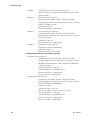
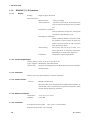
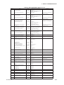
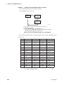
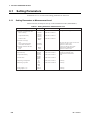
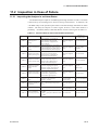
1.1.1.2 Characteristics
GD402 specification list
Item
Density
lb/ft3
Specific Gravity
Molecular Weight
Concentration vol%
0-5
0 - 140
0.1
0.1
4
approx. 5 sec
+/-1 % FS
+/- 0.001
or +/-0.5%FS *
approx. 5 sec
+/-1 % FS
+/- 0.0001
or +/-0.5%FS*
approx. 5 sec
approx. 5 sec
+/-1 % FS
+/- 0.001
or +/-0.5%FS*
+/-1 % FS
+/- 0.02
or +/-0.5%FS*
+/- 1
+/- 0.5% or Concentration
equivalent to
+/-0.001kg/m3 *
+/- 0.003/month
+/- 0.002/month
+/- 0.003/month
+/- 0.07/month
Concentration equivalent
to +/- 0.003 kg/m3/month
0-6
Response Time 90%
Linearity
Long term stability
Density
0 - 0.4
0.01
Range
Minimum Range
Repeatability
kg/m3
0 - 100
Concentration equivalent
to 100 kg/m3
approx. 5 sec
T2_01A.eps
*: Whichever is greater
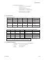
Density is the basic measurement, the other representations are derived from the Density data.
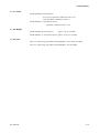
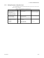
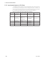
Item
Range
Minimum Range
H2 in Air vol% H2 in CO2 vol% Air in CO2 vol%
85 - 100
0 - 100
0 - 100
Response Time 90%
Linearity
Repeatability
approx. 5 sec
+/- 1
+/- 0.5
approx. 5 sec
+/- 1
+/- 0.5
approx. 5 sec
+/- 1
+/- 0.5
Drift
+/- 0.5/month
+/- 0.5/month
+/- 0.5/month
Caloric value MJ/m3
0 - 130
Caloric value equivalent to
0.100 kg/m3
approx. 5 sec
+/- 1 % FS
+/- 0.5%FS or Caloric value
equivalent to 0.001kg/m3*
Caloric value equivalent to
+/- 0.003kg/m3 /month
Caloric Value and BTU are possible representations of the Density.
GD402 does not contain table information, only a single mathematical equation.
British Thermal Unit KBTU/ft3
0 - 3.5
Caloric value equivalent to
0.100 kg/m3
approx. 5 sec
+/- 1 % FS
+/- 0.5%FS or Caloric value
equivalent to 0.001kg/m3 *
Caloric value equivalent to
+/- 0.0025/month
*: Whichever is greater
T2-01B.eps
1.1.1.3 Sample gas conditions
Sample gas: All gases except for corrosive gas and acetylene gas
IM 11T3E1-01E
Temperature:
-10 to 50˚C (non-condensing)
Pressure:
Max. 588.4kPa (abs)
Gas flow:
0.1 to 1 l/min
1-3
1. SPECIFICATIONS
1.1.1.4 Output Signals
Output 1:
4-20 mA DC
Isolated from inputs; load resistance: 600Ω maximum
(Load resistance of 250-550Ω required when in the BRAIN communication mode)
Output 2:
4-20 mA DC
Isolated from inputs; load resistance: 600Ω maximum
1.1.1.5 Power Supply
Rated voltage range:
100 to 240 V AC, 24V DC
Allowable voltage range:
85 to 264 V AC, 21.6 to 26.4V DC
Rated frequency:
50 or 60 Hz
Allowable frequency range: 47 to 63 Hz
1.1.1.6 Power Consumption
Max. 12 W
1.1.1.7 Safety and EMC Compliance
Safety Standards: EN61010-1
●
Altitude at installation site: Max. 2000 m above sea level
●
Installation category based on IEC1010: Overvoltage category II*1
●
Pollution degree based on IEC1010: Pollution degree 2*2
EMC Standards:
(Achieved only when GD402G converter is used with GD40G detector.)
Emission:
EN61326 Class A
EN61000-3-2
EN61000-3-3
AS/NZS CISPR11
Immunity: EN61326 Annex A and F
Influence in the immunity environment signal input: Within ±50 g/m3 at
physical density output.
*1 "II" applies to electrical equipment which is supplied from the fixed
installation like distribution board.
*2 "Pollution degree" describes the degree to which a solid, liquid, or gas which
deteriorates dielectric strength or surface resistivity is adhering. "2" applies
to a normal indoor atmosphere.
1-4
IM 11T3E1-01E
1. SPECIFICATIONS
1.1.2
GD40G, T, V, R Detector
1.1.2.1 Material exposed to gas
SUS316 stainless steel , Acrylonitrile Butadiene Rubber and Fluorine-contained
Rubber (o-ring)
1.1.2.2 Ambient conditions
Temperature:
-10 to 60˚C (14 to 140˚F)
Humidity:
5 to 95% RH
Installation:
Pipe-mounted or on panel
Construction:
Explosion-proof and Intrinsically safe.
(See 1.1.1.1 "System Components")
Though the detector construction makes it relatively insensitive to sudden changes in
the gas temperature, extra precision can be achieved by keeping ambient temperature conditions as constant as possible. In measurements where optimum precision is required it is
therefore not recommended to install the detector in an outdoors environment, especially
not if such installation is prone to direct sunlight.
1.1.2.3 Finish
Cover:
equivalent to Munsell 0.6GY3.1/2.0
Case:
equivalent to Munsell 2.5Y8.4/1.2
1.1.2.4 Weight
Approx. 7kg (with pipe mounting bracket)
1.1.2.5 Detector unit
When the system is ordered to be used as a hydrogen purity analyzer an optional pressure analyzer is required for pressure compensation.
•If /EJAJ1 or /EJAF2, /EJAF3, /EJAF4 are ordered, the detector unit and the pressure
transmitter and the tubing in between will all be integrated on a single mounting plate. This
allows the space where the pressure transmitter is normally mounted to be used effectively
for other purposes.
IM 11T3E1-01E
1-5
1. SPECIFICATIONS
1.1.3.
1.1.3.1
GD402G,T, V, R Converter
Display
Reading:
Digital (5 digits maximum)
Data items shown:
Measured value:
Always on display.
Alarm indications:
Abnormal concentration, abnormal pressure
range of input and abnormal value of calibration .
Parameters for calibration:
Time of calibration, settling time, starting time
of calibration and calibration cycle
Self-diagnostic indications:
Sensor oscillation shutdown, abnormal oscillation frequency of sensor, failure in sensor temperature detection, failure in A/D conversion
stage and memory failure
Alarm settings:
The contact state can be set to either "normally open (NO)" or "normally closed (NC)"
depending on the needs of the application.
Temperature:
Temperature of gas being measured
1.1.3.2 Contact Outputs/Input
Contact capacity: 250 V AC at 3A or 30 V DC at 3A
Types of signals: Maintenance, Fail, Hi/Lo alarms
Contact input:
Signal for switching between the Hydrogen Purity meter and the Replacement meter
1.1.3.3 Calibration
Manual (one touch), Semi automatic, Automatic calibration
1.1.3.4 Communication
Protocol:
BRAIN communication
Data items that can be transmitted by the hand-held terminal are numerical data, such as concentration, temperature and pressure, alarm
setpoint and self-diagnostic parameters.
1.1.3.5 Ambient Conditions
Temperature:
-10 to 55˚C (14 to 131˚F)
Humidity:
5-95% RH
1.1.3.6 Installation
Non-explosion-proof models:
Pipe-, panel- or wall-mounted
Explosion-proof models: Pipe-mounted
1-6
IM 11T3E1-01E
1. SPECIFICATIONS
1.1.3.7 Finish
Model GD402G (general purpose):
Front cover:equivalent to Munsell 0.6GY3.1/2.0
Case:equivalent to Munsell 2.5Y8.4/1.2
Model GD402T, V, R (explosion-proof):
equivalent to Munsell 0.6GY3.1/2.0
1.1.3.8 Weight
Model GD402G (general purpose):
Approx. 3 kg (6.6 pounds)
Model GD402T, V, R (explosion-proof): Approx. 15 kg (33.1 pounds)
1.1.3.9 Fuse
250V 1A quick acting type authorized VDE/SEMCO 100 to 240V AC Model
250V 2A quick acting type authorized VDE/SEMCO 24V DC Model
IM 11T3E1-01E
1-7
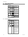
1. SPECIFICATIONS
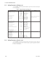
1.2
1.2.1.
Model Specifications
Gas Density Converter
Model
Basic code
Option
code
Description
GD402G
General purpose model, 6
cable glands included.
GD402T
FM certified explosion proof
model. Gland threads
1/2NPT. No cable glands
included.
CSA certified explosion
proof model. Gland threads
1/2NPT. No cable glands
included.
GD402V
TIIS certified explosion proof
model. Gland threads G3/4.
No cable glands included.
GD402R
Power
supply
24V DC
100-240V AC
-D
-A
Label and
approval
English label
TIIS approval, English label
(only GD402R)
-E
-J
English
Instruction Manual -E
Options
(only GD402G)
/PA
/U
Panel mounting
Universal (Pipe and Wall)
Mounting
[Note] Explosion -proof models, GD402T, V, R have only pipemounting hardware as standard.
T01.EPS
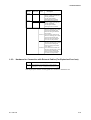
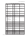
1.2.2.
Gas Density Detector
Model
Basic code
Option
code
Description
GD40G
General purpose detector.
1/4NPT gas threads and
1/2NPT gland threads. No cable
gland included.
Mounting hardware included.
GD40R
TIIS certified explosion proof
detector. Rc1/4 gas threads and
G1/2 gland threads.
Cable gland included.
Mounting hardware included.
Label
approval
-E
English label, no approval (only
GD40G)
TIIS approval, English label
(only GD40R)
-J
Options
/EJAJ1
TIIS certified EJA mounted with
detector on mounting plate. Rc1/4
gas threads and G1/2 gland thread.
Cable gland included.(only GD40R)
/EJAJ1T TIIS certified EJA mounted with
detector on mounting plate. Rc1/4
gas threads and G1/2 gland thread.
Cable gland included.
EJA with TAG (only GD40R)
/EJAF2 EJA mounted with detector on
mounting plate.1/4NPT gas threads
and 1/2NPT gland threads. No cable
gland included.(only GD40G)
/EJAF2T EJA mounted with detector on
mounting plate.1/4NPT gas threads
and 1/2NPT gland threads. No cable
gland included.
EJA with TAG (only GD40G)
T02-1.EPS
1-8
IM 11T3E1-01E
1. SPECIFICATIONS
Model
Basic code
Option
code
GD40T
FM certified explosion proof
detector. 1/4NPT gas threads and
1/2NPT gland thread.
No cable gland included.
Mounting hardware included
CSA certified explosion proof
detector. 1/4NPT gas threads and
1/2NPT gland thread.
No cable gland included.
Mounting hardware included.
GD40V
Options
Description
/EJAF3
FM certified EJA mounted with
detector on mounting plate.1/4NPT
gas threads and 1/2NPT gland
thread. No cable gland included.
(only GD40T)
EJAF3T FM certified EJA mounted with
detector on mounting plate.1/4NPT
gas threads and 1/2NPT gland
thread. No cable gland included.
EJA with TAG (only GD40T)
CSA certified EJA mounted with
/EJAF4
detector on mounting plate. 1/4NPT
gas threads and 1/2NPT gland
thread. No cable gland included.
(only GD40V)
/EJAF4T CSA certified EJA mounted with
detector on mounting plate. 1/4NPT
gas threads and 1/2NPT gland
thread. No cable gland included.
EJA with TAG (only GD40V)
T02-2.EPS
1.2.3.
Hardware for Connection with External Cables (For Explosion-Proof use)
Part No.
Description
L9811LL
G3/4 explosion proof cable gland. Cable's outside
diameter 8 to 16 mm. Used for the GD402R converter.
T03.EPS
Note: Specify the number of cable glands for converter in hazardous area
IM 11T3E1-01E
1-9
1. SPECIFICATIONS
1.2.4
Two-Core, Double-Shielded Cable
Normally two conductor shielded cable can be used, but when failure arises from noises
disturbance, this cable is recommended for connection between the GD402 converter and
GD40 detector.
Model
Basic code
Description
GDW
Two core, double shielded
cable, both ends finished with
cable pins.
Length
-L
Length in meters, 500 meter
maximum.
T04.EPS
1.2.5.
Brain Terminal (Optional)
Model
Suffix Codes
Option
code
BT200
Description
Brain terminal [Note]
-N
-P
Printer
–
Standard type (without printer)
With printer
00
Always 00
/
Options
[Note] BT200 has following accessories, two communication cables, one with
IC clips and another with alligator clips, handy carrying case and five
AA 1.5 V dry batteries.
T05.EPS
OPTIONS FOR BT200
Options
Description
Communication cable
(Note 1)
With a 5-pin connector
(for the signal conditioner)
Intrinsically safe type
CSA Intrinsically safe approval
(Note 1)(Note 2)
Class I, Groups A, B, C and D Temp.
(Note 1) Optional code /C1 can not be combined with /CS1.
(Note 2) Applicable only for Model BT200-N00.
Option
codes
/C1
/CS1
T06.EPS
See GS 1C0A11-E for "BT200" brain terminal in detail.
1.2.6.
Pressure transmitter (Optional)
/EJAJ1 means TIIS certified EJA310.
/EJAF2 means general purpose model EJA310.
/EJAF3 means FM certified EJA310.
/EJAF4 means CSA certified EJA310.
See GS 01C221D01-00E for "EJA310" pressure transmitter in detail if a different selection from pre-selected options seems necessary.
1-10
IM 11T3E1-01E
1. SPECIFICATIONS
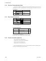
1.3
External Views and Dimensions
1.3.1
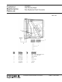
GD402G Converter (Non-Explosion-Proof)
Unit: mm (in.)
Weight: approximately 3 kg (6.6 pounds)
Four holes, 6 mm (0.24) in dia.,
8 mm (0.31) deep M6
80 (3.1)
144 (5.7)
80 (3.1)
144 (5.7)
23
112 (4.4)
(0.9)
38
(1.4)
36
(1.4)
Cable inlet (21 mm (0.9) in dia.)
Compatible with a Pg13.5 cable gland
36
36
(1.4) (1.4)
Grounding terminal (4 mm (0.16) screws)
IM 11T3E1-01E
Cable gland
Connection
A, B
•Pressure transmitter
•Analog output •Contact Input
C
•Detector
D, E
•Contact Output
F
•Power Supply
GD402G.EPS
1-11
1. SPECIFICATIONS
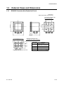
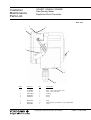
1.3.2.
Pipe- and Wall-Mounting Hardware (Optional)
• Hardware for Pipe Mounting: GD402G -
-
-
Unit: mm (in.)
Weight: approximately 3 kg (6.6 pounds)
/U
Four holes,
6 mm (0.2) in dia.
50 (2)
200 (7.9)
174 (6.9)
188 (7.4)
Optional
hardware
100 (4)
Mounting pipe of JIS 50 A nominal size
(60.5 mm in outer dia.)
-
/U
Four holes,
6 mm (0.2) in dia.
15 35
Optional
hardware
(0.6) (1.4)
224 (8.8)
13 (0.51)
Three holes,
10 mm (0.4) in dia.
• Hardware for Panel Mounting: GD402G -
-
/PA
12 mm (0.5) maximum
(panel thickness)
Four holes,
6 mm (0.2) in dia.
100 (4)
Weight: approximately 3 kg (6.6 pounds)
Optional
hardware
Dimensions of panel cutout
139
+2
0
100 (4)
23
(0.9)
-
70 (2.8)
(5.47 +0.08
)
0
-
135 (5.3)
224 (8.8)
• Hardware for Wall Mounting: GD402G -
139 +2
0
178 (7)
1-12
(5.47 +0.08
)
0
IM 11T3E1-01E
1. SPECIFICATIONS
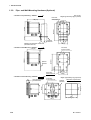
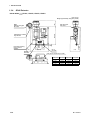
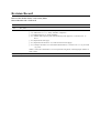
1.3.3.
GD402T, V, R Converter (Explosion-proof)
Unit: mm (in.)
Weight: approximately 15 kg (33.1 pounds)
Approx. 200 (7.9)
Approx. 212 (8.3) in dia.
Approx. 209 (8.2)
Approx. 173 (6.8)
Approx. 182 (7.2)
Approx.
36 (1.4)
140 (5.5)
Approx. 242 (9.5)
A
Side view from arrow A direction
Cable glands not included
54 39 24 (0.9)
(2.1) (1.5)
200 (7.9)
Grounding terminal
(5 mm (0.2) screw)
Two holes, 8 mm (0.3) in dia.,
one on each side
of JIS 50 A nominal size
(60.5 mm (2.4) in outer dia.)
(Used to fix the
pipe-mounting hardware)
Pipe-mounting hardware
A
B
C
D
E
F
56
(2.2)
Cable gland
Mounting pipe
Six wiring holes, G3/4 threaded (GD402R)
1/2NPT threaded (GD402V, T)
56
(2.2)
Connection
A
•Power Supply
B, C
•Contact Output
D
•Detector
E, F
•Pressure from Transmitter,
•Analog Output, •Contact Input
■ GD402■
■ Standard Accessory List
Model
GD402G
GD402R
GD402T
GD402V
IM 11T3E1-01E
Item
Qty
Part Number
Fuse
1
A1109EF (Power Supply: 100-240 V AC)
A1111EF (Power Supply: 24 V DC)
Universal Mount Set
1
K9171SS
Panel Mount Set
Surge Protector
1
Fuse
1
K9171ST
K9215LP
A1109EF (Power Supply: 100-240 V AC)
A1111EF (Power Supply: 24 V DC)
Bracket
1
Bracket
U-Bolt Assy
Bolt
1
2
1
Bolt
2
1
K9214HD
K9214HE
D0177XL-A
Y9835NU
Y9820NU
1-13
1. SPECIFICATIONS
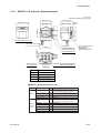
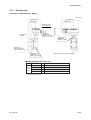
1.3.4
GD40 Detector
• Model GD40■
■ -■
■ /EJAJ1, /EJAF2, /EJAF3, /EJAF4
(120)
Unit: mm (in.)
Weight: approximately 15 kg (27.8 pounds)
GD40
Detector wiring port
See Table
(350 (13.8))
Cable gland is included
only in EJAJ1
EJA wiring port
See Table
35
(93)
Gas out
See Table
85
(350 (13.8))
5
Four panel-mounting
holes, 12 mm in
diameter
Approx.
26
Approx.
105
(40
(1.6))
(35)
Gas in
See Table
Cable gland is included only in /EJAJ1
Option code GD40 wiring EJA wiring
/EJAJ1
G1/2
G1/2
/EJAF2
1/2NPT
1/2NPT
/EJAF3
1/2NPT
1/2NPT
/EJAF4
1/2NPT
1/2NPT
1-14
(196)
Gas out/in
Rc1/4
1/4NPT
1/4NPT
1/4NPT
IM 11T3E1-01E
1. SPECIFICATIONS
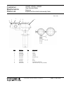
1.3.5
Detector Unit
• Hardware for Pipe Mounting : GD40■
■
Unit: mm (in.)
Approx. 191 (7.5)
Approx. 264 (10.4)
Approx. 92 (3.6)
Approx. 193 (7.6)
Wiring hole,
GD40R: G1/2
GD40G, T, V: 1/2NPT
Pipe-mounting
hardware
Approx. 117 (4.6)
Grounding terminal
(3 mm (0.11) screw)
Sample gas inlet
GD40R: Rc1/4
GD40G, T, V: 1/4NPT
Mounting pipe
(JIS 50 A (60.5 mm in
outer dia.) nominal size)
Sample gas outlet
GD40R: Rc1/4
GD40G, T, V: 1/4NPT
Note: Cable gland is included only in GD40R.
■ GD40■
■ Standard Accessory List
Model
GD40G
GD40R
GD40T
GD40V
Item
U-Bolt Assy*1
Bracket*1
Qty
Part Number
4
1
D0177XL-A
Bracket*1
1
K9214HE
Gland*2
1
G9601AM
K9214HD
*1: Not supplied when option code "/EJAF2," "/EJAF3," or "/EJAF4" is specified.
*2: Supplied only for GD40R.
IM 11T3E1-01E
1-15
1. SPECIFICATIONS
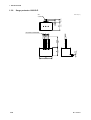
1.3.6
Surge protector: K9215LP
Unit: mm (In.)
11
(0.43)
28.5
(1.12)
5.5
(0.22)
Ø4.2
(0.17)
200
(7.86)
28
4.5
2
(0.18)
1
(1.1)
M4 SCREW TERMINAL
41
(1.61)
1-16
IM 11T3E1-01E
2. INSTALLATION, WIRING AND PIPING
2. INSTALLATION, WIRING AND PIPING
The Model GD402 Gas Density Meter is thoroughly inspected at the factory and carefully packed to ensure the equipment does not suffer any damage during transportation.
The package should also be handled with care when unpacking to prevent the equipment
from undergoing severe mechanical shock. After unpacking, visually check the equipment
to ensure that it is free from any damage.
Although the detector has no controls on it, it may need to be accessed for inspection or
for other reasons. Install the detector in a location as close as possible to where the gas is
sampled and where maintenance can be easily carried out. The converter has a display
with controls on it; thus, you should install it so that the keys are positioned directly in
front of you when working.
Note that there must be a clearance of at least 400 mm at the back of the converter
Model GD402G, GD402T, GD402V and GD402R since cables are wired to the back by
removing the screwed rear cover.
IM 11T3E1-01E
2-1
2. INSTALLATION, WIRING AND PIPING
2.1
Installing the Detector
The GD40 ■ detector is a explosion-proof with intrinsically safe sensor instrument (explosion-protection code: Refer to 1.1.1.1). Install the detector in a location where the following conditions are satisfied.
2.1.1
Selecting the Location
● Explosion-protection construction
Before installing the detector in an explosion-hazardous area, ensure that the area
conforms to the explosion-protection code noted above.
● No corrosive gases
Corrosive gases are not desirable because they may damage the electrical components in
the detector.
● Slight mechanical vibration
Although the detector is vibration-resistant, vibration may loosen the connections of the
external wiring.
● No exposure to direct sunlight
Exposure to direct sunlight may raise the temperature in the detector to abnormal levels,
and should therefore be avoided. Note that such abnormal temperature levels can also
result from heat radiated from high-temperature equipment around the detector.
● Humidity maintained between 5% and 95% RH
Avoid choosing a location that is likely to be exposed to abnormally high or low
humidity over a prolonged period. It is recommended that the converter be used at a
humidity between 25% and 85% RH.
● No exposure to rain water
Even though the detector is rainproof, whenever possible install it where it is protected
from water splashes. The reasoning for this is that the detector cover may need to be
removed for maintenance or for other reasons.
● Altitude of installation site is lower than 2,000 m.
2-2
IM 11T3E1-01E
2. INSTALLATION, WIRING AND PIPING
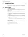
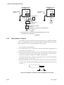
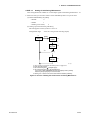
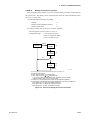
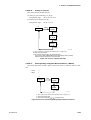
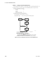
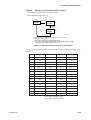
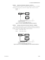
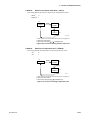
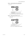
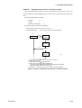
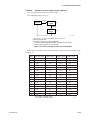
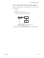
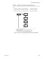
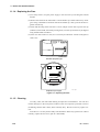
2.1.2
GD40T (FM Explosion-proof with Intrinsically Safe Approval)
NON-HAZARDUS
LOCATIONS
HAZARDUS
LOCATIONS
475mm (18") Max.
Sealing Fitting
Conduit
GD40T
Fig. 2.0.1
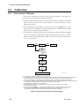
1. GD40T Gas density detector for use in hazardous (classified) locations:
* Explosion-proof for Class I, Dividion 1, Groups B, C, and D;
Dust-Ignitionproof for Class II, III, Division 1, Groups E, F, and G with Intrinsically
Safe sensor for Class I, II, III, Division 1, Groups B, C, D, E, F and G.
* Enclosure Rating: NEMA 4X
* Temperature Code: T5
* Ambient Temperature: -10 to 60°C
2. Wiring
* All wiring shall comply with National Electric Code ANSI/NAPA 70 and Local
Elecrical Codes.
* Seal all conduits within 18 inches. Refer to Fig 2.0.1
3. Operation
* Note a warning label worded as follows.
WARNING:
OPEN CIRCUIT BEFORE REMOVING COVER.
* Take care not to generate mechanical spark when access to the instrument and peripheral
devices in hazardous locations.
4. Maintenance and Repair
* The instrument modification or parts replacement by other than authorized
representative of Yokogawa Electric Corporation is prohibited and will void the
approval of Factory Mutual Research Corportation.
IM 11T3E1-01E
2-3
2. INSTALLATION, WIRING AND PIPING
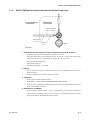
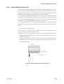
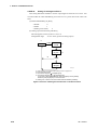
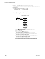
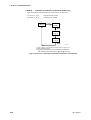
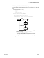
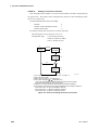
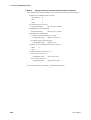
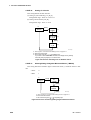
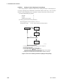
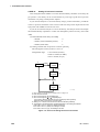
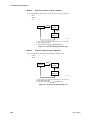
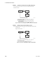
2.1.3
GD402T (FM Explosion-proof Approval)
GD402T
Conduit
HAZARDUS
LOCATIONS
475mm (18") Max.
Sealing Fitting
NON-HAZARDUS
LOCATIONS
Fig. 2.0.2
1. GD402T gas density meter converter for use in hazardous (classified) location:
* Explosionproof for Class I, Division 1, Groups B, C, and D;
Dust-ignitionproof for Class II, III, Division 1, Groups E, F and G
* Enclosure Rating: NEMA 4X
* Temperature Code: T6
* Ambient Temperature: -10 to 55°C
2. Wiring
* All wiring shall comply with National Electrical Code ANSI/NFPA 70 and Local
Electrical Codes.
* Seal all conduits within 18 inches. Refer to Fig 2.0.2.
3. Operation
* Note a warning label worded as follows.
WARNING:
OPEN CIRCUIT BEFORE REMOVING COVER.
* Take care not to generate mechanical spark when access to the instrument and peripheral
devices in hazardous locations.
4. Maintenance and Repair
* The instrument modification or parts replacement by other than authorized
representative of Yokogawa Electric Corporation is prohibited and will void the
approval of Factory Mutual Research Corporation.
2-4
IM 11T3E1-01E
2. INSTALLATION, WIRING AND PIPING
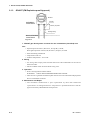
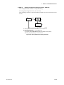
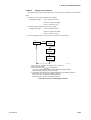
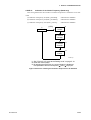
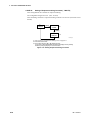
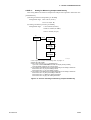
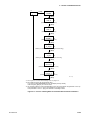
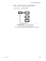
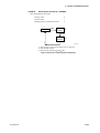
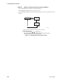
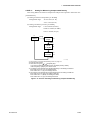
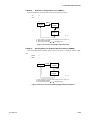
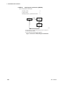
2.1.4
GD40V (CSA Explosion-proof with Intrinsically Safe Approval)
NON-HAZARDUS
LOCATIONS
HAZARDUS
LOCATIONS
500mm (20") Max.
Sealing Fitting
Conduit
GD40V
Fig. 2.0.3
1. GD40V Gas density detector for use in hazardous locations:
* Explosion-proof for class I, Division 1, Groups B, C, andD;
Dust-Ignitionproof for Class II, III, Division 1, Groups E, F, and G with Intrinsically
Safe sensor for Class I, II, III, Division 1, Groups B, C, D, E, F and G.
* Enclosure Rating: Type 4X
* Temperature Code: T5
* Ambient Temperature: -10 to 60°C
2. Wiring
* All wiring shall comply with Canadian Electrical and Local Elecrical codes.
* Note a warning label worded as follows.
WARNING:
A SEAL SHALL BE INSTALLED WITHIN 50cm OF THE
ENCLOSURE. Refer to Fig. 2.0.3.
3. Operation
* Note a warning label worded as follows.
WARNING:
OPEN CIRCUIT BEFORE REMOVING COVER.
WARNING:
SUBSTITUTION OF COMPONENTS MAY IMPAIR INSTRINSIC
SAFETY.
* Take care not to generate mechanical spark when access to the instrument and peripheral
devices in hazardous locations.
4. Maintenance and Repair
* The instrument modification or parts replacement by other than authorized
representative of Yokogawa Electric Corporation is prohibited and will void the
certification of CSA International.
IM 11T3E1-01E
2-5
2. INSTALLATION, WIRING AND PIPING
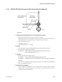
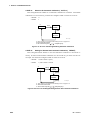
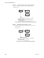
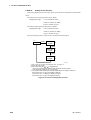
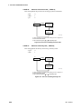
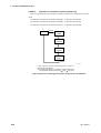
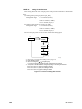
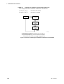
2.1.5
GD402V (CSA Explosion-proof Approval)
GD402V
HAZARDUS
LOCATIONS
Conduit
500mm (20") Max.
Sealing Fitting
NON-HAZARDUS
LOCATIONS
Fig. 2.0.4
1. GD402V gas density meter converter for use in hazardous locations:
* Explosion-Proof for Class I, Division 1, Groups B, C, andD;
Dust-ignitionproof for Class II, III, Division 1, Groups E, F, and G
* Enclosure Rating: Type 4X
* Temperature Code: T6
* Ambient Temperature: -10 to 55°C
2. Wiring
* All wiring shall comply with Canadian Electrical Code and Local Elecrical Codes.
* Seal all conduits within 50cm of the enclosure. Refer to Fig.2.0.4.
* Note a warning label worded as follows.
WARNING:
A SEAL SHALL BE INSTALLED WITHIN 50cm OF THE
ENCLOSURE.
3. Operation
* Note a warning label worded as follows.
WARNING:
OPEN CIRCUIT BEFORE REMOVING COVER.
* Take care not to generate mechanical spark when access to the instrument and peripheral
devices in hazardous locations.
4. Maintenance and Repair
* The instrument modification or parts replacement by other than authorized
representative of Yokogawa Electric Corporation is prohibited and will void the
certification of CSA International.
2-6
IM 11T3E1-01E
2. INSTALLATION, WIRING AND PIPING
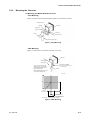
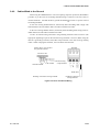
2.1.6
Mounting the Detector
The detector is designed for pipe mounting.
Unit : mm(in.)
Approx. 191 (7.5)
Approx. 264 (10.4)
Approx. 92 (3.6)
Approx. 193 (7.6)
Wiring hole,
GD40R: G1/2
GD40V: 1/2NPT
GD40T: 1/2NPT
GD40G: 1/2NPT
Pipe-mounting
hardware
Approx. 117 (4.6)
Grounding terminal
(3 mm (0.11) screw)
Sample gas inlet
GD40R: Rc1/4
GD40V: 1/4NPT
GD40T: 1/4NPT
GD40G: 1/4NPT
Mounting pipe
(JIS 50 A (60.5 mm in
outer dia.) nominal size)
Sample gas outlet
GD40R: Rc1/4
GD40V: 1/4NPT
GD40T: 1/4NPT
Note: Cable gland is included only in GD40R.
Figure 2.1 Vertical Mounting
IM 11T3E1-01E
2-7
2. INSTALLATION, WIRING AND PIPING
2.2
Installing the Converter
The GD402 converter comes in either the non-explosion-protected Model GD402G or
explosion-protected Model GD402T, V, R (explosion-protection code: Refer to 1.1.1.1).
Choose the Model GD402T or V or R if the converter is to be used in a hazardous area.
2.2.1
Selecting the Location
● Ease of operation
A location where you can easily view the readings on the display and work with the
keys. Installing the converter closer to the detector will ease your maintenance work,
including calibration.
● Explosion-protection construction
When installing the converter in an explosion-hazardous area, ensure that the area
conforms to the explosion-protection code noted above.
● No corrosive gases
Corrosive gases are not desirable because they may damage the electrical components in
the detector.
● Slight mechanical vibration
Although the detector is vibration-resistant, vibration may loosen the connections of the
external wiring.
● No exposure to direct sunlight
Exposure to direct sunlight may raise the temperature in the converter to abnormal
levels, and should therefore be avoided. Note that such abnormal temperature levels can
also result from heat radiated from high-temperature equipment around the converter.
● Humidity maintained between 5% and 95% RH
Avoid choosing a location that is likely to be exposed to abnormally high or low
humidity over a prolonged period. It is recommended that the converter be used at a
humidity between 25% and 85% RH.
● No exposure to rainwater
Even though the converter is rainproof, whenever possible install it where it is protected
from water splashes. The reasoning for this is that the converter cover may need to be
removed for maintenance or for other reasons.
● Altitude of installation site is lower than 2,000 m.
2-8
IM 11T3E1-01E
2. INSTALLATION, WIRING AND PIPING
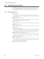
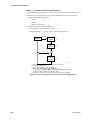
2.2.2
Mounting the Converter
(1) Mounting the Model GD402G Converter
· Pipe Mounting
Figure 2.2 shows the mounting hardware and how to mount the converter.
Bracket setscrew
Converter
Bracket
Bracket for
pipe moounting
Nuts (two)
U-bolt
Waschers (two)
Stanchion (50A pipe)
Figure 2.2 Pipe Mounting
· Wall Mounting
Figure 2.3 shows how to mount the converter on a wall.
Converter
Mounting hole
(three places)
M8 bolt (not supplied)
Note : The converter for wall
mounting comes with the same
mounting hardware as that of a
pipe-mounting model.
When installing the converter on
a wall, use the bracket only.
Use a bolt long enough to fit into
the mounting hole.
Bracket
Unit : mm
144
102
Center of
the converter
35
70
3-M8 screw-hole or
3-Ø10 thoufh-hple
Dimension of cutout for wall mounting
Figure 2.3 Wall Mounting
IM 11T3E1-01E
2-9
2. INSTALLATION, WIRING AND PIPING
• Panel Mounting
Figure 2.4 shows how to mount the converter on a panel.
Unit : mm
Panel
139 +2
0
Converter
Bracket
139 +2
0
Insert the converter in
the panel cutout before
attaching the brackets.
Setscrew (two)
Dimensions of cutout for panel mounting
Figure 2.4 Panel Mounting
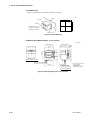
(2) Mounting the Model GD402T, V, R Converter
Unit: mm (in.)
Approx. 200 (7.9)
Approx. 209 (8.2)
Approx.
36 (1.4)
Approx. 173 (6.8)
200 (7.9)
Mounting pipe
Two holes, 8 mm (0.3) in dia.,
one on each side
of JIS 50A nominal size
(60.5 mm (2.4) in outer dia.)
(Used to fix the
pipe-mounting hardware)
Approx. 242 (9.5)
182 (7.2)
A
140 (5.5)
Approx. 212 (8.3) in dia.
Side view from arrow A direction
Cable glands not included
Pipe-mounting hardware
Figure 2.5 Mounting Explosion-proof Converter
2-10
IM 11T3E1-01E
2. INSTALLATION, WIRING AND PIPING
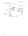
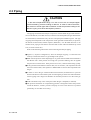
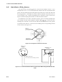
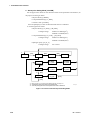
2.3 Piping
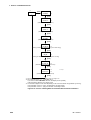
CAUTION
In the case of replacement range, H2 in CO2 or Air in CO2, the output happen
to be fluctuated by pressure loading to detector. In order to reduce the effect,
flow meter is to be set upper side of detector so that the pressure loading to the
detector is going to be about atmospheric pressure.
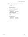
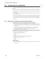
The piping connected to the analyzer comprises a line that feeds the gas under measurement to the detector, a line that returns (or releases to the atmosphere) the gas exhausted after measurement, and lines that carry the zero- and span-point calibration gases. The type
of piping chosen depends on the composition of the gas under measurement, its pressure,
the amount of dust mixed, and the response (dead time). It is advisable however to use
stainless-steel piping of sizes from 6 mm and 4 mm in outer and inner diameters up to JIS
15A (21.7mm in outer dia.).
Refer to the following instructions when connecting the analyzer piping.
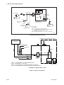
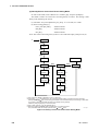
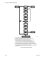
● Figure 2.6, "System Configuration," shows an example of piping. Connect the lines
securely to ensure that there is no gas leakage in the system.
● Make sure the pressure of the sampled gas is no greater than 0.5 MPa when measured at
the detector inlet. If the pressure is too high, use a pressure-reducing valve to regulate
the pressure to a normal level. If the pressure is too low, it must be raised using a pump.
● If the gas under measurement contains dust, mist or moisture, such impurities must be
removed. Install a filter, mist separator or dehumidifier to remove these impurities from
the gas.
● In order to return the gas exhausted after measurement, the difference in pressure
between the detector inlet and the point of returning the gas must be 0.5 kPa minimum.
Choose piping with a large inner diameter to minimize pressure loss in the return gas
line.
● ALWAYS install a stop valve at the point where the gas is sampled (or returned).
● The pressure transmitter for compensating pressure is designed to detect the pressure
inside the detector; install a pressure lead pipe as close to the detector as possible
(preferably, no more than 0.5 m away).
IM 11T3E1-01E
2-11
2. INSTALLATION, WIRING AND PIPING
Switching valve
Note 1
P1
Sample gas line
EJA (Explosion-proof
pressure transmitter)
Filter
Flowmeter
Note 3
Note 2
P2
Note 4
Gas for zero point
calibration
Detector unit (EJA and GD40 detector
mounted on plate)
(Supplied by Yokogawa)
Note 4
Gas for span
point calibration
Pressure regulator
for gas cylinder
Supplied by customer.
< Max. 0.5 MPa (71psi)
Note 1: P1 (inlet pressure) =
> 0.5 kPa (0.071psi)
Note 2: P1 (inlet pressure) - P2 (outlet pressure) =
(depending on the size and length of the pipe)
Note 3: Flow rate = 0.1 to 1 l/min
Note 4: The cylinder pressure must be reduced to P1 (inlet pressure).
Fig 5-04.eps
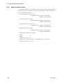
(1) Example of density and calorie
Explosion proof pressure transmitter
P
Generator
Calibration gas
CO2
Note 4
AIR
Note 3
P2
Note 1
P1
Vent
Flow meter
Note 2
Note 1 : P1 (inlet pressure ) <
= Max 0.5884 MPa (abs.)
Note 2 : The flowrate = 0.1 to 1 l/min
Note 3 : P1 (Input pressure ) - P2 (Output pressure ) >
= 0.5 kPa
Note 4 : The cylinder pressure must be reduced to P1(inlet pressure).
Detector unit
(2) Example of Hydrogen purity meter
Figure 2.6 System Configuration
2-12
IM 11T3E1-01E
2. INSTALLATION, WIRING AND PIPING
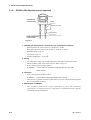
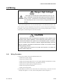
2.4 Wiring
Danger High Voltage!
Some parts of the analyzer's internal assembly have high voltages. Inadvertent contact with those parts may result in electrical
shock or injury. ALWAYS turn off the power to the analyzer before removing the rear or front cover by using external circuit
breaker.
This section explains how to wire the GD402 analyzer. Note that this document is limited to the basic system configuration only (detector, converter and pressure transmitter).
For details on the wiring of instruments used to receive analog output signals or contact
output signals, see their respective instruction manuals.
CAUTION
GD402 gas density meter is shipped after adjusting the both of detector and
converter in pairs. When installation, confirm wheter the serial number on both
of converter and detector are in pairs or not. If mismatched in pairs, converter is
to be out of order. When converter or detector supplied individually, enter the
detector constants, described on inside the lid of GD40, into converter so that
GD402 is going to be well.
In detail, please refer to Figure 5.30 on page 5-36, Figure 6.31 on page 6-35
or Figure 7.28 on page 7-32.
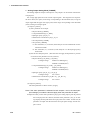
2.4.1
Wiring Procedure
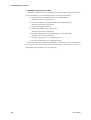
(1) The types of cables wired to the GD402 analyzer are:
• Cable wired to power supply
• Cable wired to detector input
• Cables wired to output signals (two)--or one signal if BRAIN communication is used
• Cables wired to contact outputs (five)--provided as necessary
• Cable wired to contact input--provided as necessary
• Cables wired to pressure transmitter
• Cables wired to the ground
(2) The GD402 converter has six cable inlets for external wiring. Wire the converter
through cable glands. As a rule, choose cable glands as shown in Figure 2.7.
IM 11T3E1-01E
2-13
2. INSTALLATION, WIRING AND PIPING
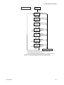
Unit : mm(in.)
Cable inlet (21 mm (0.9) in dia.)
Compatible with a Pg13.5 cable gland
38
(1.4)
36
(1.4)
Cable gland
36
36
(1.4) (1.4)
Grounding terminal (4 mm (0.16) screws)
Connection
A, B
•Pressure transmitter
•Analog output •Contact Input
C
•Detector
D, E
•Contact Output
F
•Power Supply
Figure 2.7 Choice of Cable Glands
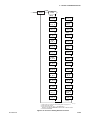
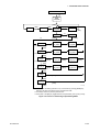
(3) The following explains the general wiring procedure for each type of converter.
<Wiring the GD402T, V, R converter>
CAUTION
The rear cover and the metal plugs at the external-wiring connections are
fixed onto the converter case with hex setscrews. Before removing the cover,
be SURE to loosen the setscrews. If you rotate the cover or a plug without loosening the setscrews, their threads may be severed, making the cover unremovable.
When the rear cover or any of the cable glands or plugs are removed, handle
them with utmost care so that the threads are not damaged. When re-attaching
it onto the converter, clean the threads so they will not be damaged due to such
foreign matters as dust.
• Loosen the setscrews and remove the rear cover by rotating it counterclockwise.
• Guide the required external-wiring cables through the cable glands to the converter.
Beware of the correct polarities.
• After wiring, securely fasten the rear cover and cable glands.
<Wiring the GD402G converter>
• Loosen the setscrews in the four corners and remove the front cover.
• Remove the terminal cover. Guide the required external-wiring cables through the
cable glands to the converter. Beware of the correct polarities.
• After wiring, reinstall the terminal cover and front cover in place.
2-14
IM 11T3E1-01E
2. INSTALLATION, WIRING AND PIPING
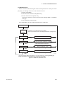
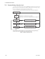
GD402
Converter
14
MAINTENANCE
Contact output
15
MAINT
16
ALARM
Contact output
17
19
+
-
ANLG
OUT1
+
ALM
+
FAIL
ANLG
OUT2
SNSR
PWR
+
18
FAIL
Contact output
CONT
INP
-
1
Contact input
2
3
Isolated 4 - 20 mA Output
with BRAIN Communication
4
5
Isolated 4 - 20 mA Output
6
20
SPAN/FUNC
22
SELECT GAS
Contact output
23
24
Power supply
100 to 240V AC or 24V DC
25
26
ZERO/SEL GAS
SNSR
INP
L or +
-
8
+
9
-
10
Pressure Transmitter
+
N or -
GD40
11
DET +
INP - 12
G
SHIELD
✽
Surge protector 1
7
Case-grounding
terminal
Case-grounding
terminal
Detector
+
21
-
FUNCTION
Contact output
13
Case-grounding
terminal
Intrinsic safety
Grounding ✽2
Class A grounding
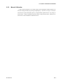
Cable List
Terminal
Indication
Shield
Requirement
MAINTENANCE
Contact output
MAINT
Unshielded
ALARM
Contact output
ALM
Unshielded
FAIL
Contact output
FAIL
Unshielded
FUNCTION
Contact output
SPAN
Unshielded
SELECT GAS
Contact output
ZERO
Unshielded
Contact input
CONT IN
Shielded
Analog output1
ANLG OUT1
Shielded
Analog output2
ANLG OUT2
Shielded
Pressure
transmitter input
SNSR PWR
SNSR INP
Shielded
Detector input
DET INP
SHIELD
Shielded
Supply
L, N, G
Unshielded
Requirement
For outdoor wiring, cable length should be less than 30 m ✽3 .
Shield should be grounded at one end only.
Total resistance should not exceed 50 ‰.
For outdoor wiring, cable length should be less than 30 m ✽3 .
Shield should be grounded at one end only.
Maximum load resistance including wire resistance is 600 ‰. When
BRAIN communication is used, it is 250 to 550 ‰.
Total resistance should not exceed 50 ‰.
For outdoor wiring, cable length should be less than 30 m ✽3 .
Shield should be grounded at one end only.
Total resistance should not exceed 50 ‰.
For outdoor wiring, cable length should be less than 30 m ✽3 .
Connect shield to SHIELD terminal on converter.
✽1
Surge protector is not provided with GD402T/V/R type converter as standard.
Surge protector and terminal box should be installed in order to meet the requirements of CE marking.
✽2 Intrinsic safety grounding
GD402V, GD40V; All wiring should comply with Canadian Electrical Code and Local Electrical Codes.
GD402T, GD40T; All wiring should comply with National Electrical Code and ANSI/NFPA 70 and
Local Electrical Codes.
✽3 Restriction on cable length does not apply to GD402T/V/R type converter.
Figure 2.8 Terminals on the Converter
IM 11T3E1-01E
2-15
2. INSTALLATION, WIRING AND PIPING
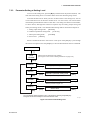
CAUTION
The following instructions should be observed for the GD402G converter to meet the
CE marking requirements.
1. Connect the supplied surge protector to the power supply.
2. The length of the following cables should be less than 30 m. However, this
restriction does not apply when both detector and converter stay indoors and their
cables do not run outdoors. For details, read Subsection 2.4.1, "Wiring Procedure."
1) Detector input
2) Pressure transmitter input
3) Analog output1, 2
4) Contact input
Electrical Noise Protection
If a malfunction due to noise occurs, strengthen measures against noise.
For example, ground the detector body or use a double-shielded cable. If a doubleshielded cable is used, ground shields of each conductor at one end. Ground one end of the
outer shield on the detector side to the detector case and connect the other end on the converter side to terminal 13. See the User's Manual for more instructions on cable installation.
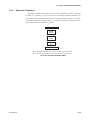
Contact Input Function of the Hydrogen Purity Meter
For hydrogen purity meter, the contact input is used for range selection.
Open: Concentration measurement for air in carbon dioxide
Close: Concentration measurement for hydrogen in carbon dioxide
Contact Output Specifications
Specification
Contact Type:
Voltage free, dry contact (mechanical relay contact output)
Contact rating:
250 V AC 3A or 30 V DC 3A
Contact arrangement: NO/NC, selectable
Contact Type:
Voltage free, dry contact (mechanical relay contact output)
Contact rating:
250 V AC 3A or 30 V DC 3A
Contact arrangement: NC, fixed
MAINT
ALM
FAIL
SPAN/FUNC
ZERO/SEL GAS
Function contact; use distinguish between H2 purity meter and Replacement meter.
Select gas contact; use distinguish measuring ranges in Replacement meter.
Contact Type:
Voltage free, dry contact (mechanical relay contact output)
Contact rating:
250 V AC 3A or 30 V DC 3A
Contact arrangement: NO/NC, selectable
NOTE ; The following cable with an OD size between instruments is used.
Converter
2-16
Instrument
Detector
GD40R
GD402R
Explosion-proof
Ø 10 to Ø 13.5
GD402G
Non-Explosion-proof
Ø 10 to Ø 12
Pressure transmitter
EJA310
Output signal
Contact input/output
Ø 8 to Ø 16
Ø 8 to Ø 16
Ø 6 to Ø 12
Ø 6 to Ø 12
Ø 8.5 to Ø 11
IM 11T3E1-01E
2. INSTALLATION, WIRING AND PIPING
2.4.2
Cable Wired to Power Supply
The GD402G bears the CE marking. When using the meter in a place where the CE
marking is obligatory, or when performance meeting the CE marking requirements is
needed, the following wiring is required. (Note that the following wiring is not required
when the power supply is 24 V DC.)
●
Install en external switch or circuit breaker to the power supply of the converter.
●
Use an external switch or circuit breaker that is rated at 5 A and conforms to IEC 947-1
or IEC 947-3.
●
Install the external switch or circuit breaker in the same room as the converter is in
stalled.
●
The external switch or circuit breaker should be installed in a location that allows
operator access and should be marked a power supply switch to the converter.
●
Connect the supplied surge protector to the power supply. This protects the power
supply circuit of the converter from surge.
CAUTION
The GD402R converter contains a power switch and a fuse. The switch cannot be operated however, if the converter is installed in an explosion-hazardous
area; it must be left placed in the ON position. When Power ON/OFF, use external cuicuit breaker.
Wiring is for supplying power supply that meets specifications to the GD402 converter.
Use a 3-conductor cable with a size of 1.25 to 2.5 mm2 and an outside diameter of 8 to 16
mm for 100-240 VAC type and a 2-conductor cable for 24 V DC type. A surge protector
is not provided with GD402T/V/R type converter.
Wire the cable as instructed below:
(1) Strip the sheath 7 mm at the cable end to be connected to the converter.
(2) Connect the cable to terminals, L, N, and G or terminals + and - on the converter.
Loosen the terminal screw, insert the stripped part of the wire into the terminal hole,
and fix the cable by tightening the screw. (adequate tightening torque: 0.4 N•m)
(3) The length of wire between the converter and a connecting device for the surge pro
tector should not exceed 1 m.
(4) To connect the surge protector, use a terminal box or relevant device. Wires of the
surge protector have a M4 ring terminal crimped.
(5) Connect black cables of the surge protector to terminals L and N, and the green cable
to terminal G. (Terminal G is internally connected to the case-grounding terminal.)
IM 11T3E1-01E
2-17
2. INSTALLATION, WIRING AND PIPING
GD402■ Converter
24V DC type
GD402■ Converter
100-240V AC type
SUPPLY
LN G
Case-grounding
terminal
Case-grounding
terminal
Surge Protector
SUPPLY
+ -G
✼1
1m
max
Green cable
24V DC
Terminal box ✽1
External circuit breaker
Rating: 5A
Use IEC947-1 or IEC947-3 compliant product.
100 to 240V AC
50/60Hz
✽1
Surge protector and terminal box should be installed in order to meet
the requirements of CE marking.
Figure 2.9
2.4.3
Cables Wired to Outputs
These cables are used to transmit 4-20 mA DC signals and carry out BRAIN communication. Use shielded cables of 8 to 16 mm in finished outer diameter and 0.75 mm2 minimum in thickness (or a two-core shielded cable for single output).
Wire the cables as instructed below:
(1) Use cables that are 0.75 to 2.5 mm2 thick. Treat the cable ends by stripping the core
wires back 7 mm (see Figure 2.10).
(2) Wire the cable for output 1 to terminals 3 and 4 on the block and the cable for output 2
to terminals 5 and 6 on the block. Beware of the correct polarities. Note that only terminals 3 and 4 (output 1) are effective for BRAIN communication.
Loosen the terminal screws, insert the stripped ends of the core wires into the terminals,
and fasten the screws to fix the cable.
(3) Ground the shielding wire at a given terminal on the converter; do not ground the other
end of the cable. (The appropriate tightening torque for the internal wiring terminals is
0.4 N•m.)
7mm
Figure 2.10 Examples of Treatment on Cable End Wired to the Converter
2-18
IM 11T3E1-01E
2. INSTALLATION, WIRING AND PIPING
2.4.4
Cables Wired to Contact I/Os
The contact I/Os of the GD402 converter comprise the start-of-calibration contact (input), the FAIL, ALARM and MAINTENANCE contacts, and the contacts for operating the
solenoid valves for span and zero calibrations. Choose the type of cables for a group of
calibration-purpose contacts and for a group of other contacts separately.
For wiring to the calibration contact output, use a cable of 8 to 16 mm in finished outer
diameter and 1.25 mm2 minimum in thickness. For wiring to other contacts, use a cable of
8 to 16 mm in finished outer diameter and 0.13 to 1.25 mm2 in thickness, while choosing
the number of core wires depending on the number of contacts used.
Since the contact outputs are voltage-free, driving such devices as alarm lamps requires
a separate power supply. For the contact input (start of calibration), provide a voltage-free
signal.
Wire the cables as instructed below:
(1) Use cables 0.13 to 1.25 mm2 thick. Treat the cable ends by stripping back the core
wires to 7 mm from the end (see Figure 2.10).
(2) Wire the cables to their respective given terminals on the block, being careful not to
mistake one terminal for another. For terminal numbers assigned to the respective contacts I/Os, see Figure 2.8.
Loosen the terminal screws, insert the stripped ends of the core wires into the terminals,
and fasten the screws to fix the cables. (The appropriate tightening for the internal wiring terminals is 0.4N•m)
Terminal
Tightening screw
Cable inlet
Cable
Figure 2.11 Connection between terminal and cable
IM 11T3E1-01E
2-19
2. INSTALLATION, WIRING AND PIPING
2.4.5
Cable Wired to GD40■
■ Detector
The cable wired to the GD40■
■ detector comes from the GD402 converter. Use a
shielded cable of 10 to 13.5 mm in finished outer diameter that suits the dedicated cable
gland. Wire the cable through the cable gland, being careful not to connect the cable with
the wrong polarities. Attach M4-size (4-mm) crimp-on terminals to the ends of the core
wires (see Figure 2.10). Connect the shielding wire to terminal 13 on the converter (see
Figure 2.8). When crimping the terminals, use tools that fit the terminals.
If a malfunction occurs and it is assumed to be due to noise, use a double-shielded cable
(for example, the cable with Yokogawa's number GDW-■
■ ■ ■).
■ Connect the outer
shielding wire to terminal 13 on the converter and the other end of the wire to the grounding terminal on the detector. Connect the inner shielding wires to the grounding terminal
on the converter (see Figure 2.13).
Class A
grounding terminal
Terminals for
wiring to converter
Figure 2.12 Configuration of Detector Terminals
GD40T, V, R
Detector
GD402G, T, V, R
Converter
Class A
grounding terminal
11 12 13
Inner shielding
wires
Outer shielding wire
Outer shielding
wire
Do not connect the inner shielding wires here.
Figure 2.13 Connection Between Detector and Converter When Using a Double-Shielded
Cable
2-20
IM 11T3E1-01E
2. INSTALLATION, WIRING AND PIPING
2.4.6
Cables Wired to the Ground
When using the GD40R detector in an area requiring explosion protection, BE SURE to
ground it as per the Class A Grounding Standard using a conductor of at least 2 mm2 in
nominal thickness. Also BE SURE to ground the GD402■
■ converter as per the Class D
Grounding Standard.
In the case of using GD40T detector, Intrinsically Safe Grounding shall comply with
National Electrical Code ANSI / NFPA 70 and Local Electrical Codes.
In the case of using GD40V detector, Intrisically Safe Grounding shall comply with Canadian Electrical Code and Local Electrical Codes.
Use No. 26 internal wiring terminals or the grounding terminals of the converter. (The
appropriate tightening torque for the internal wiring terminals is 0.4 Nm.) When using the
detector's grounding terminals, attach M4 crimp terminals to the ends of the grounding
cables. When crimping the terminals, use tools that fit the terminals.
Terminal
Joining advice of Converter
case ground terminal
Converter case
Ground terminal
Lock washer
Ground wiring
crimp terminal
Earth cable
Earthing of enclosure wiring terminal
Earthing of internal
wiring terminal
Figure 2.14 Power and Ground Wiring
IM 11T3E1-01E
2-21
3. OPERATION
3. OPERATION
This chapter explains how to operate the Model GD402 Gas Density Analyzer.
3.1
Preparation for Operation
CAUTION
(1) DO NOT supply power to the analyzer when inspecting it.
(2) Leave the power switch which is built in the converter, in the ON position.
(3) DO NOT open the terminal box cover with the power turned on, if the analyzer is
installed in an explosion-hazardous area.
(4) When using the converter under high ambient temperatures, be careful as the metal
parts of the converter will also be hot.
3.1.1
Inspecting Installation, Piping and Wiring Workmanship
Before turning the power on, inspect workmanship with regards to installation, piping
and wiring as instructed below:
● Examine how the GD402 gas density meter and its peripheral equipment are installed.
● Check the sample-gas line, which feeds the GD40■
■ detector, for any gas leakage.
● Inspect the system to ensure that the GD402 analyzer and its peripheral equipment are
wired correctly. After inspection, shut the terminal box cover securely.
● Place the power switch built in the GD402T, GD402V, GD402R converter (explosionprotected) in the ON position.
IM 11T3E1-01E
3-1
3. OPERATION
3.1.2
Supplying Power
First make sure that when the GD402 analyzer is turned on, no control instruments connected to the analyzer will come into operation by the signals transmitted from the analyzer. Next, turn on the external power switch to start the analyzer. At that point, make
sure the internal power switch is in the ON position if the converter is an explosion-protected model.
After power-on, the analyzer will begin to operate in the measurement mode.
[Major Items Shown in Measurement Mode]
● Measured Values
In the Message Selection mode under the DISP mode, choose the item you want to
show.
Item
No. of Digits and Position
of Decimal Point
Message
Physical density
X.XXXX
KG/M3
Physical density
X.XXXXX
LB/FT3
Compensated density
X.XXXX
X.XXXXX
KG/M3
LB/FT3
XXX.XXX
X.XXXX
MJ/M3
Compensated density
Calorific value
Calorific value
Specific gravity
X.XXXX
KBTU
Molecular weight
XXX.XX
SP GR
MOL
Concentration
XXX.X
VOL%
T3.1.ai
● Types of Messages
• Measurement units
• Error number (shown if an error occurs)
• Alarm number (shown if an alarm occurs)
● HOLD and FAIL Indications (shown regardless of whether the analyzer is in the
measurement mode or not)
• HOLD appears when the analyzer is in a hold state.
• FAIL appears if an error occurs.
3-2
IM 11T3E1-01E
3. OPERATION
3.1.3
Display on Operation Panel and Operation Keys
Figures 3.1 and 3.2 illustrate the operation panels of the Model GD402G and GD402T,
GD402V, GD402R Converters, respectively.
The operation panel has a display and operation keys. Use the seven operation keys on
the panel to set operation parameters, and so on.
Case
Operation level
display panel
Display
unit
Setting level / Service level
display panel
Operation
key
Setting level / Service level
selection switch
Figure 3.1 Functional Description of GD402G Converter (Cover Open)
Display
unit
Case
Operation
key
Operation level
display panel
Setting level / Service level
display panel
Setting level / Service level
selection switch
Figure 3.2 Functional Description of GD402T, GD402V, GD402R Converter (Cover
Open)
IM 11T3E1-01E
3-3
3. OPERATION
3.1.4
Basic Key Operation
The basics of key operation are the selection between modes/levels, the selection and execution of the function/action, and entry of data values.
1. Selecting Between Modes at the Operation Level (See Chapter 4 for
details.)
●You can enter the measurement mode by pressing the [MODE] key while the analyzer is
in a mode other than the measurement mode.
When switching between modes, note the following two points:
(1) Press the [MODE] key once. The message field first shows "DISP" in Figure 3.3-(1)
(then password is not selected in first condition). And then changes to look like one shown
in Figure 3.3-(2).
(1)
When password is selected, the message field shows
<*PASSW>, prompting you to enter a passwords.
Type [XXX] and press the [ENT] key. The
message field changes to look like one shown left.
(2)
In the display shown left, the [YES] and [NO]
fields blink. Pressing the [YES] key will change
the message to [KG/M3], indicating the analyzer
is now in the density mode.
Figure 3.3 Examples of Display at Operation Level (In case of the Density Meter)
(2) In the display shown in Figure 3.3-(1), each press of the [NO] key changes the message field, enabling you to choose a different mode by its indication.
2. Selecting Between Modes at the Setting Level(See Chapter 4 for details.)
(1) In the measurement mode, press the [*] key (to select between settings).
(1)
When password is selected, the message field shows
<*PASSW>, prompting you to enter a passwords.
Type [XXX] and press the [ENT] key. The
message field changes to look like one shown left.
(2)
In the display shown left, the [YES] and [NO]
fields blink. Pressing the [YES] key will change
the message to read [OUT1] , indicating the
analyzer is now in the analog output setting mode.
Figure 3.4 Examples of Display at Setting Level
(2) In the display shown in 3.4-(1), each press of the [NO] key changes the message
field, enabling you to choose a different mode by its indication.
3-4
IM 11T3E1-01E
3. OPERATION
3. Entering Data Values
CAUTION
The data you have entered do not disappear even if you turn off the power. If
the data you have entered are provisional, reenter the normal data.
The following explains how to make changes to existing data entries.
In the display shown in Figure 3.4-(2), pressing the [YES] key causes the message field
to default to[*DENS]. Pressing the[YES] key once again changes the message to
[*Z_CAL], the range's lower limit setting, and makes the indication of the lower limit
blink.
Assume the existing data entry of the range's lower limit is 1.2927. To change the value
to 2.0535, follow the instructions given below:
(1) Press the [>] key so "1" starts blinking.
(2) Press the [^] key until the blinking "1" changes to "2".
(3) Press the [>] key until the next digit begins blinking. Then, press the [^] key until
the blinking 'tens' digit changes to "0".
(4) Next, press the [>] key until the next digit begins blinking. Then, press the [^] key
until the blinking digit changes to "5".
(5) Next, press the [>] key until the next digit begins blinking. Then, press the [^] key
until the blinking digit changes to "3".
(6) Next, press the [>] key until the next digit begins blinking. Then, press the [^] key
until the blinking digit changes to "5".
(7) Press the [ENT] key. This confirms the value "2.0535".
(1)
(2)
Pressing the [ENT] key enters the value shown
in the data field.
In the display shown in Figure 3.4 (2), pressing the
[YES] key will change the display to look like this.
Figure 3.5 DisplayDuring Data Setting
IM 11T3E1-01E
3-5
3. OPERATION
4. Entering a Password
If you need, a password can be entered to proceed into the operation, setting or service
level. When you attempt to enter that level, a password-entry message (password prompt)
like one shown in Figure 3.6-(1) appears. The required password is "XXX". (See section
"4.2 Setting Lists".)
(1)
When password is selected, pressing the [MODE]
key, then the [✽] key, changes the display to
look like this.
(2)
Type the password (XXX) and then press the
[ENT] key. If you type a wrong password,
you cannot enter the level.
Figure 3.6 Password Prompt and the Reading of a Password Typed
3.1.5
Checking the Setting Parameters
Set up the relevant parameters, display unit, analog output and others, to meet individual
operating requirements. GD402 gas density meter is designed to changed into density,
calorific meter and hydrogen purity meter according to application. (Select "50" in Service
code, page 5-34 and change parameter you need.)
3.1.6
Calibrating the Analyzer for Correct Readings
For details on the calibration of the analyzer for correct readings, see Chapter 8, 9 or 10.
3-6
IM 11T3E1-01E
3. OPERATION
3.1.7
Checking the Analyzer for Performance
When the required parameters have been completely set, bring into operation all equipment composing the measurement loop. Keep this equipment operating for a while. After
making sure there is no problem with the equipment, go into normal operation.
For reference, the following summarizes the setting functions (related to signals) of the
GD402 analyzer that are used to obtain the optimum operating conditions.
[Functions Related to the Output Signal]
●The output signal can be held at a value immediately before calibration or at a desired
value during calibration or at the setting/service level. This is to prevent the output
signal from adversely affecting the operation of the equipment configuring the
measurement loop (default setting: the output signal is held at the value immediately
before).
[Functions Related to the High/Low-Limit Alarm Contact Output]
●Select the parameters for which the alarms are raised, and then set their respective
high/low-limit setpoints. The analyzer transmits an alarm contact signal if any of
these setpoints is exceeded. (Define the voltage-free contacts and the state of contacts
at the service level.)
[Functions Related to the FAIL Contact Signal]
●If a FAIL state occurs, an appropriate message appears on the LCD display. For
details on these functions, see Chapter 11.
[Contact output of H2 purity / Replacement meter]
●According to switching of Replacement meter, the statas of contact and display (LED)
is changed as following. (The statas of contact output are to be set in Service level,
CODE 05. See page 7-19.)
•
Hydrogen purity meter
RANGE
Replacement
Meter
H2 in CO2
AIR in CO2
Hydrogen Purity?
Replacement Meter
H2 in AIR
H2 in CO2
AIR in CO2
FUNC
NORMAL
ACTIVE
ACTIVE
SEL GAS
LED
ACTIVE
NORMAL
ON
OFF
NORMAL
ACTIVE
NORMAL
OFF
ON
OFF
FUNC: Identification signal of Hydrogen Purity?Replacement Meter. (contact)
SEL GAS: Range identification signal of Replacement Meter. (contact)
T3.2.ai
[The status of contact output]
Power Supply
OFF
Power Supply
ON
FAIL
SEL
OPEN
CLOSE
NORMAL: CLOSE
FAILURE: OPEN
FUNC CLOSE
MAINT
CLOSE
ALM
CLOSE
The states of contact are to be set in Service level, CODE 05.
T3.3.ai
IM 11T3E1-01E
3-7
3. OPERATION
3.2
Normal Operation
In normal operation, there is no need for working with the GD402 analyzer except when
calibrating it. Unless there is any failure found, carry out maintenance, inspection, and so
on at the same time the analyzer is calibrated. The analyzer is designed to prohibit you
from calibrating it or setting each parameter unless you have entered the password (XXX).
(See section "4.2 Setting Lists".)
3.2.1
Starting Operation
Follow the procedure below to start operation.
Turn on the external power switch.
➝
Set the operating parameters.
➝
Calibration the analyzer for correct zero and span setpoints.
➝
Completing these steps return to the <MEASURE> mode.
The following details the operations required in this procedure.
(1) The analyzer, when turned on, indicates the density value. See Figure 5.3, 6.3 or 7.3
for the operations used to change to the required unit of density.
(2) Set the relevant operating parameters by checking and modifying their default values in
order to meet individual operating requirements.
(3) Supply the zero and span gases to check readings. If the readings contain errors, the
analyzer must be calibrated. For details on calibration, see Chapter 8, 9 or 10.
(4) When calibration is complete, the analyzer returns to the <MEASURE> mode.
3-8
IM 11T3E1-01E
3. OPERATION
3.2.2
Corrective Actions in Case of Failure
If the GD402 analyzer senses a failure, it sends out a FAIL contact output signal through
terminals 18 and 19. In such a case, the output signal is held at either the value held immediately before or at the preset value for each setting.
The message field indicates the type of error by the error code. Should a failure occur,
check the nature of the failure and take corrective action without delay. Table 3.1 summarizes the numeric codes of errors that may occur in the measurement mode. For details on
each type of error, see Table 11.2 on page 11-4.
Table 3.1 Errors that May Occur in the Measurement Mode
Error No.
Err. 01
Err. 02
Err. 03
Err. 04
Err. 05
Nature of Failure
Corrective Actions
Sensor shutdown
Faulty oscillation frequency of sensor
Sensor's failure to detect temperature
Failure in A/D converter
Failure in memory
Reset the power and contact service personnel.
Reset the power and contact service personnel.
Contact service personnel.
Contact service personnel.
Contact service personnel.
T3.3.ai
3.2.3
Inspection and Maintenance
Due to the operating principle (multi-mode self-excited oscillation circuitry), the sensor
has only the slightest marginal drift, which is, in fact, generated by the detector itself or a
result of contamination from dust, etc. Therefore, the GD402 analyzer basically does not
have to undergo any inspection or maintenance. Periodical inspection and maintenance are
recommended however, to ensure optimum performance. For details on inspection and
maintenance, see Chapter 11.
IM 11T3E1-01E
3-9
3. OPERATION
3.3
Shutdown and Restart
3.3.1 Measures for Shutdown
Data set in the converter are retained even when the power is turned off. If the system
needs to be shut down over a prolonged period, turn off the power. Any foreign matter that
accumulates and hardens on the detector or any corrosive substance that condenses on the
detector can be the cause of problems. Fully purge the sensor with fresh air (instrument
air). Cleaning of the sensor is also recommended where it is appropriate; consult
Yokogawa.
3.3.2
Measures for Restarting
Visually check all component equipment of the analyzer before you resume measurement after a long-term shutdown of the analyzer. Make sure the wiring and piping connections have not loosened.
3-10
IM 11T3E1-01E
4. FUNCTIONS
4. FUNCTIONS
When using the GD402 meter, set data and select functions according to the measuring
conditions. This chapter describes the structures of function.
4.1
4.1.1
Summary of Setting Operations
Measurement, Operation, Setting and Service
Parameters can be set by selecting the appropriate mode. These modes are classified
into four levels: measurement, operation, setting, and service.
[Measurement Level]
This level is used to view various measured values.
[Operation Level]
This is basically a level used to select between items to be viewed in the measurement
mode and a parameter to be measured, and to perform operations relating to routine inspection and/or maintenance such as calibration.
[Setting Level]
At this level, there are modes for setting data related to analog outputs, calibration data
and alarm contact outputs.
[Service Level]
The GD402 analyzer has numerous functions. At this level, there are modes for selecting the functions necessary for system operation.
IM 11T3E1-01E
4-1
4. FUNCTIONS
4.1.2
Key Operations
Keys can be operated in an "interactive" manner. Operate the keys according to the information in the data or message field, information pointed to by the pointer (mode indication), and/or information in the key operation indicators. For basic key operations, see
Subsection 3.1.4.
[Interactions]
● Flashing pointer
This inquires whether you want to go to the mode being pointed at or move the pointer
to the next mode. When the system indicates the modes for the setting or service level, the
message is preceded by an asterisk (*). When you enter one of the modes, the pointer stops
flashing and remains continuously lit.
● Flashing key operation indicators
This prompts you to choose an indicator from the indicators flashing on the display and
press the corresponding key.
● Flashing numerals in data field
This asks whether you want to change the flashing numeral or move to the next digit and
have it flash. Press the appropriate key. If neither of these actions is required, press the
[ENT] key.
[Aborting the Setting Operation]
Press the [MODE] key. Normally, the[MODE] key is used to move from the measurement (<MEASURE>) mode to a mode at the operation level. It is also used to return to the
measurement mode from other modes.
4-2
IM 11T3E1-01E
4. FUNCTIONS
4.1.3
Points to Be Noted When Making Settings
(1) Password
Password is not selected in first condition. When password is necessary, refer to Section
"4.2 Setting Lists" and selected password what you need. If password is selected, you are
not allowed to access any mode unless you enter the given password (XXX).
A password prompt appears when:
● at the operation level, the [MODE] key is pressed during the measurement mode, or
● at the setting level, the [✽] key is pressed during the measurement mode.
● at the service level, the[YES] key is pressed with [*SERV] displayed.
(2) Related Parameters
If any change has been made to a particular parameter, check its relationship with parameters set in other modes so that there will not be any inconsistency.
[Parameters to Check When the Analog Output Settings Are Changed]
a. High/low-limit alarm setpoints and contact outputs
b. Fixed value for held output signal
[Parameters to Check When High/Low-limit Alarm Setpoints Are Changed]
a. Alarm actions (low-limit alarm or high-limit alarm operation)
b. Analog output settings
IM 11T3E1-01E
4-3
4. FUNCTIONS
4.2 Setting Lists
● The GD402 Gas Density meter comes in 3 different models (and model codes) to meet
several measurement conditions: (1) Density meter, (2) Calorie meter, and (3) Hydrogen
purity meter.
The values measured by the different models are as follows.
(1) Density meter :
Density, compensated density, specific gravity, molecular
weight, concentration and calorie.
(2) Calorie meter :
Density, compensated density, and calorie
(3) Hydrogen meter : Density, compensated density, H2 in air, Air in CO2, and H2 in
CO2.
● The following describes the conditions required when using the GD402 Gas Density
meter.
After following the procedure below, set a model code and select a password.
(1) Select a model code for each service in "Selecting the instruments" function of each
service code. For example, if you select model 1, you can use the analyzer as a calorie meter. (See Fig 5.29 on page 5-34, Fig 6.30 on page 6-33 or Fig 7.27 on page 730.)
code 0 : Density meter
1 : Calorie meter
2 : Hydrogen purity meter
(2) Next, set a password, if you need. (See Fig 5.27 on page 5-33, Fig 6.28 on page 6-32
or Fig 7.25 on page 7-29.)
(3) Other parameter settings can now be set.
Set parameters according to the selected model code and password.
(1) Density meter:See Chapter 5.
(2) Calorie meter: See Chapter 6.
(3) Hydrogen purity meter: See Chapter 7.
4-4
IM 11T3E1-01E
5. DENSITY / PARAMETER SETTING
5. DENSITY / PARAMETER SETTING
CAUTION
Password is not selected in first condition. When password is necessary,
refer to Section "4.2 Setting Lists".
This chapter describes how to set parameters of Density meter.
If select Calorie meter, see Chapter 6.
If select Hydrogen meter, see Chapter 7.
Conversion Table
1 lb/ft3
= 16.01847 kg/m3
1 kBTU/ft3
= 37.25901232 MJ/m3
X degF
= (X-32)/1.8
1 psi
= 6.894756794 kPa
Density of Air
= 1.2928 kg/Nm3
= 0.08070684 lb/ft3
IM 11T3E1-01E
5-1
5. DENSITY / PARAMETER SETTING
5.1
Setting Parameters
Subsections 5.1.1 to 5.1.4 show the setting parameters for each level.
5.1.1
Setting Parameters at Measurement Level
When turned on, the analyzer starts up in the measurement mode (<MEASURE>).
Table 5.1 Setting Parameters at Measurement Level
Mode/Setting parameter
Measurement mode
Indication of measurement value
Physical density
Compensated density
Specific gravity
Calorific value
Molecular weight
Concentration
Indication of message
Unit
Error symbol and number
Alarm mark and number
Indication of HOLD and FAIL
HOLD
FAIL
DISP mode
Physical density
Compensated density
Specific gravity
Calorific value
Molecular weight
Concentration
Measured gas temperature
Measured gas pressure
Analog output 1 (%)
Analog output 2 (%)
5-2
Display
Data to be Set (or Conditions)
Remarks
See Figure 5.2 for key operation.
KG/M3
LB/FT3
KG/M3
LB/FT3
SP GR
MJ/M3
KBTU
MOL
VOL%
Set the unit in CODE 21.
Set the unit in CODE 21.
Set the unit in CODE 22.
ERR.NO
ALM.NO
HOLD
FAIL
DISP
KG/M3
LB/FT3
KG/M3
LB/FT3
SP GR
MJ/M3
KBTU
MOL
VOL%
°C
°F
KPA
MPA
PSI
MA1%
MA2%
Set the unit in CODE 21.
Set the unit in CODE 21.
The unit is the one set in the service level.
Appears if an error occurs.
Appears if an alarm occurs.
Appears even during other modes.
Appears during a HOLD state.
Appears if a failure occurs.
See Figure 5.2 for key operation.
Selection of parameters to be
measured in the measurement
mode.
Set the unit in CODE 22.
Set the unit in CODE 23.
Read-only
Set the unit in CODE 20.
Read-only
Read-only
Read-only
IM 11T3E1-01E
5. DENSITY / PARAMETER SETTING
5.1.2
Setting Parameters at Operation Level
Press the [MODE] key and enter the password (XXX) to gain access to this level (see
Figure 5.1 for key operation).
Table 5.2 Setting Parameters at Operation Level
Mode/Setting parameter
Calibration mode
Semi-automatic calibration
Manual calibration
Setting of zero-point density
Setting of span-point density
Zero/span-gas valve operation
Zero-gas valve operation
Span-gas valve operation
Sample-gas valve operation
IM 11T3E1-01E
Display
Data to be Set (or Conditions)
Remarks
SEM.CAL One-touch calibration
See Figure 8.3 for key operation.
MAN.CAL
See Figure 8.4 for key operation.
*Z_DNS
*S_DNS
VALVE No setting is required for manual calibration. See Figure 8.1 for key operation.
Control of zero-gas valve
Control of span-gas valve
Switching between sample and calibration
gases
5-3
5. DENSITY / PARAMETER SETTING
5.1.3
Setting Parameters at Setting Level
Press the [✽] key and enter the password (XXX) to gain access to this level (see Figure
5.4 for key operation).
Table 5.3 Setting Parameters at Setting Level
Mode/Setting parameter
Display
*RANGE
*OUT1
*DENS
*C_DNS
*SP_GR
*CALRY
*MOL
*CONCT
*TEMP
*PRESS
Analog output setting
Output 1
Set a parameter to be output.
Set the zero and span points.
Physical density
Specific gravity
Calorific value
Molecular weight
Concentration
*OUT2
*CAL.DT
*Z_DNS
Output 2 (same as output 1)
Setting of calibration data
Zero-point density
Span-point density
*S_DNS
Output hold value during calibration
*C_HLD
Setting of preset value
(Only if the preceding parameter is set
to 2 (preset value))
Alarm-point setting
Select a parameter for which an alarm is set.
Physical density
Compensated density
Specific gravity
Calorific value
Molecular weight
Concentration
Set the high/low limits.
Physical density
Specific gravity
Calorific value
Molecular weight
Concentration
5.1.4
Remarks
See Figure 5.4 for key operation.
Physical density
Compensated density
Specific gravity
Calorific value
Molecular weight
Concentration
Gas temperature
Gas pressure
No setting is required if the parameter
is temperature or pressure.
*Z_DNS,*S_DNS 0.0000 to 6.0000
0.00000 to 4.00000
*Z_CP.D,*S_CP.D 0.0000 to 6.0000
0.00000 to 0.40000
*Z_SPC,*S_SPC 0.0000 to 5.0000
*Z_CAL,*S_CAL 0.000 to 133.000
0.0000 to 3.5000
*Z_MOL,*S_MOL 0.00 to 140.00
*Z_CON,*S_CON 0.0 to 100.0
Compensated density
Compensated density
Data to be Set (or Conditions)
*PR.SET
See Figure 8.2 for key operation.
0.0000 to 6.0000
0.00000 to 0.40000
0.0000 to 6.0000
0.00000 to 0.40000
• Disable: 0
• Enable (value immediately
before) : 1
• Enable (preset value) : 2
-10.0 to 110.0
*ALARM
See Figure 5.5 for key operation.
*DENS
*C_DNS
*SP_GR
*CALRY
*MOL
*CONCT
*L_DNS,*H_DNS 0.0000 to 6.0000
0.00000 to 4.00000
*L_CP.D,*H_CP.D 0.0000 to 6.0000
0.00000 to 0.40000
*L_SPC,*H_SPC 0.0000 to 5.0000
*L_CAL,*H_CAL 0.000 to 133.000
0.0000 to 3.5000
*L_MOL,H_MOL 0.00 to 140.00
*L_CON,*H_CON 0.0 to 100.0
Setting Parameters at Service Level
Press the [✽] key and enter the password (XXX) to select the service level. When you
select this level, the analyzer shows a Code No. prompt. Type the appropriate code number and press the [ENT] key.
5-4
IM 11T3E1-01E
5. DENSITY / PARAMETER SETTING
Table 5.4 Setting Parameters at Service Level
Code No.
01
02
Item
*M_HLD
Setting of the preset hold value
*PR.SET
Setting of hold against errors
Hold enable/disable
Setting of the preset hold value
04
05
10
11
12
Display
Setting of hold during maintenance
Hold enable/disable
Setting of output-smoothing constants
Setting of contact outputs' states
Setting of pressure correction
Enable/disable/fixed value
Setting of fixed value for pressure
correction
Setting for measuring compensated
density
Setting of reference temperature
Setting of reference pressure
*E_HLD
*PR.SET
*SMOTH
*CNTCT
*P.COMP
*P.FIX
*Z_PRS
Setting of span-gas pressure
*S_PRS
See Figure 5.8 for key operation.
• Disable : 0
• Enable (value immediately before) : 1
• Enable (preset value) : 2
If "preset value" is selected in the
-10.0 to 110.0
preceding parameter.
See Figure 5.9 for key operation.
00 to 60
See Figure 5.10 for key operation.
00 to 15
See Figure 5.11 for key operation.
• Disable: 0
• Enable (measured value) : 1
• Enable (fixed value) : 2
If "fixed value" is selected in the
0.10 to 999.99kPa, 0.0001 to
preceding parameter.
9.9999MPa, 0.015 to 99.999 psi
See Figure 5.12 for key operation.
See Figure 5.13 for key operation.
Selection for automatic calibration
*AUTO.C
14
Setting for remote semi-automatic
calibration
Setting of data for automatic/semiautomatic calibration
Selection of calibration item
*REMOT
Calibration interval
• Disable : 0
• Enable (value immediately before) : 1
• Enable (preset value) : 2
-10.0 to 110.0
If "preset value" is selected in the
preceding parameter.
*C.D.TMP -20.0 to 80.0 °C, -4.0 to 176.0 °F
*C.D.PRS 0.10 to 999.99kPa, 0.0001 to
9.9999MPa, 0.015 to 99.999 psi
Setting of gas pressure
Setting of zero-gas pressure
Calibration time
Stabilization time
Starting time of calibration
Setting of year/month/day
Setting of hour/minute
Setting of unit of calibration interval
0.10 to 999.99kPa, 0.0001 to
9.9999MPa, 0.015 to 99.999 psi
0.10 to 999.99kPa, 0.0001 to
9.9999MPa, 0.015 to 99.999 psi
• Disable : 0
• Enable : 1
• Disable : 0
• Enable : 1
*CAL.P
*CAL.T
*STAB.T
*Y_M_D 00.01.01 to 99.12.31
*H_M
00.00 to 23.59
*CYCL.U Hour : 0
Day : 1
*CYCL.T Hour : 00 to 23
Day : 000 to 255
*PRES.U
• kPa : 0
• MPa : 1
• psi : 2
*DENS.U
• kg/m3 : 0
• lb/ft3 : 1
*CAL.U
• MJ/m3 : 0
• kBTU/ft3 : 1
*TEMP.U
• °C : 0
• °F : 1
21
Selection of density unit
22
Selection of calorific value unit
23
Selection of temperature unit
30
42
Setting of calendar
Setting of year/month/day
Setting of hour/minute
Showing/hiding of negative measured
value (-)
Indication of calibration coefficients
(read-only)
Zero
Span
Indication of oscillation frequency
(read-only)
Frequency F2
Frequency F4
Frequency ratio
Indication of software version (read-only)
*F2.KHZ
*F4.KHZ
*F2/F4
*REV
X.XXXXX
X.XXXXX
X.XXXXX
X.XX
43
Setting of high-resolution mode
*S_CYC
44
Setting of password
*PASS
• Normal resolution : 0
• High resolution : 1
0.0.0 to 9.9.9
45
Selecting Battery alarm detection
*BAT
50
Selecting the instruments
82
Setting Detector Constant
41
IM 11T3E1-01E
See Figure 5.15 for key operation.
Zero and span : 0
Zero : 1
Span : 2
00 to 60
00 to 60
Selection of pressure unit
40
See Figure 5.14 for key operation.
See Figure 5.16 for key operation.
20
31
Remarks
See Figure 5.7 for key operation.
13
15
Data to be Set (or Conditions)
*Y_M_D
*H_M
*MINUS
00.01.01 to 99.12.31
00.00 to 23.59
• Show : 0
• Hide : 1
See Figure 5.17 for key operation.
See Figure 5.18 for key operation.
See Figure 5.19 for key operation.
See Figure 5.20 for key operation.
See Figure 5.21 for key operation.
For leap years, the setting can cope
with 'February 29'.
See Figure 5.22 for key operation.
See Figure 5.23 for key operation.
*C_K_Z
*C_K_S
SX.XXXX
X.XXXX
See Figure 5.24 for key operation.
*MODEL
• Non detection : 0
• Detection : 1
• Density meter : 0
• Calorie meter : 1
• Hydrogen purity, replacement : 2
See Figure 5.25 for key operation.
See Figure 5.26 for key operation.
See Figure 5.27 for key operation.
See Figure 5.28 for key operation.
See Figure 5.29 for key operation.
See Figure 5.30 for key operation.
5-5
5. DENSITY / PARAMETER SETTING
5.2
Parameter Setting
[Aborting the Setting Operation]
Press the [MODE] key. Normally, the [MODE] key is used to move from the measurement mode (<MEASURE>) to a mode at the operation level. It is also used to return to the
measurement mode from other modes.
5.2.1
Parameter Setting at Operation Level
To move to the operation level, press the [MODE] key and then enter the password
(XXX). Password is not selected in first condition. When password is necessary, refer to
Section 4.2 "Setting Lists" and selected password what you need.
The operation level offers two mode categories: the measurement and calibration operation modes.
Note that the function for which you have set a data value at the setting level does not
work at all if that function is turned off at another level. For this reason, care must be taken
when dealing with modes that relate to each other.
This subsection explains the operating procedures for the levels/modes noted below.
The calibration operation mode is discussed in Chapter 8.
(1) Operation level
(2) Message display/setting mode (DISP mode)
5-6
IM 11T3E1-01E
5. DENSITY / PARAMETER SETTING
(1) Operation Level
Select a mode from the following four choices of the operation level. Each press of the
[NO] key cycles through the choices in the order shown below:
1. Display mode [DISP]
2. Semi-automatic calibration mode [SEM.CAL]
3. Manual calibration mode [MAN.CAL]
4. Valve operation mode [VALVE]
Press the [YES] key to enter the desired mode when it is indicated.
Measurement Mode
[MODE]
XXX
*PASSW
Password is not selected in first condition
(See "Figure 5.27 Process of Setting Password" on page 5-33.)
[ENT]
DISP mode
DISP
[YES]
[NO]
SEM.CAL
[YES]
See the process in Figure 8.3.
Manual calibration mode
MAN.CAL
[YES]
[NO]
[NO]
[YES]
Semi-automatic calibration mode
[YES]
[NO]
VALVE
See the process in Figure 5.2.
See the process in Figure 8.4.
[YES]
Valve operation mode
[YES]
[YES]
See the process in Figure 8.1.
F5.1.EPS
You can abort the setting operation in any of the modes by pressing [MODE] key.
Doing this will return the analyzer to the measurement mode.
Figure 5.1 Modes of Operation Level
IM 11T3E1-01E
5-7
5. DENSITY / PARAMETER SETTING
(2) Message Display/Selection Mode
Select one of the following ten parameters to be shown in the message field. Each press
of the [NO] key cycles through the choices in the order shown below:
1. Physical density [X.XXXX KG/M3] or [X.XXXXX LB/FT3]
(depends on the setting of CODE 21)
2. Compensated density [X.XXXX KG/M3] or [X.XXXXX LB/FT3]
(depends on the setting of CODE 21)
3. Specific gravity [X.XXXX SP GR]
4. Calorific value [XXX.XXX MJ/M3] or [XX.XXXX KBTU]
(depends on the setting of CODE 22)
5. Molecular weight [XXX.XX MOL]
6. Concentration [XXX.X VOL%]
7. Temperature [XXX.X °C] or [XXX.X °F]
(depends on the setting of CODE 23)
8. Pressure [XXX.XX KPA] or [X.XXXX MPA] or [XX.XXX PSI]
(depends on the setting of CODE 20)
9. Current for analog output 1 (%) [XXX.X MA1%]
10. Current for analog output 2 (%) [XXX.X MA2%]
Show the desired choice and press the [YES] key. That choice is set as a parameter to
be measured in the measurement mode (<MEASURE>). Parameters 1 to 6 are
configurable, while parameters 7 to 10 are read-only.
5-8
IM 11T3E1-01E
5. DENSITY / PARAMETER SETTING
[MODE]
*1
Measurement Mode
DISP
[YES]
X.XXXX
KG/M3
[YES] * 2,* 3
(Physical density)
[NO]
X.XXXX
KG/M3
[YES] * 2,* 3
(Corrected density)
[NO]
X.XXXX
SP GR
[YES] * 3
(Specific gravity)
[NO]
XXX.XXX
MJ/M3
[YES] * 2,* 3
(Calorific value)
[NO]
XXX.XX
MOL
[YES] * 3
(Molecular weight)
[NO]
XXX.X
VOL%
[YES] * 3
(Concentration)
[NO]
XXX.X
8C
[YES] * 2
(Measured gas temperature)
[NO]
XXX.XX
KPA
[YES] * 2
(Read only)
(Measured gas pressure)
[NO]
XXX.X
MA1%
[YES]
(Read only)
(Current for analog output1(%))
[NO]
XXX.X
MA2%
[YES]
(Read only)
(Current for analog output2(%))
[NO]
Measurement Mode
F5.2.eps
*1: See "Figure 5.1 Models of Operation Level" on page 5-7.
*2: The unit is the one set in the service level.
*3: Press the [YES] key to show the parameter in the measurement mode.
Figure 5.2 Message Display/Selection Mode (DISP Mode)
IM 11T3E1-01E
5-9
5. DENSITY / PARAMETER SETTING
5.2.2
Parameter Setting at Setting Level
To move to the setting level, press the [✽] key and then enter the password (XXX). The
main task at the setting level is to set data values such as the measuring range values.
Note that the function for which you have set data values at the setting level, will not
work if that function is turned off at another level. For this reason, care must be taken
when dealing with modes that relate to each other. The setting level has four levels/modes,
as shown below, although this subsection explains only the analog output setting and
alarm-point setting modes. The calibration data setting mode is discussed in Chapter 8.
1. Analog output setting mode
[*RANGE]
2. Calibration parameter setting mode
3. Alarm-point setting mode
4. Service level
[*CAL.DT]
[*ALARM]
[*SERVC]
Select a mode from the above four choices. Each press of the [NO] key cycles through
the choices in sequence. Press the [YES] key to enter the desired mode when it is indicated.
Measurement Mode
[ ]
*
XXX
*PASSW
Password is not selected in first condition.
(See "Figure 5.27 Process of Setting Password" on page 5-33.)
[ENT]
*RANGE
[YES]
[NO]
Analog output setting mode
[ENT]
See the process in Figure 5.4.
*CAL.DT
[NO]
[YES]
Calibratuon parameter setting mode
[ENT]
See the process in Figure 8.2.
*ALARM
[NO]
[YES]
Alarm-point setting mode
[ENT]
See the process in Figure 5.5.
*SERVC
[YES]
[NO]
Service level
[ENT]
See the process in Figure 5.7 to 5.30.
F5.3.eps
You can abort the setting operation in any of the modes by pressing the [MODE] key.
Doing this will return the analyzer to the measurement mode.
Figure 5.3 Process at the Setting Level
5-10
IM 11T3E1-01E
5. DENSITY / PARAMETER SETTING
1. Analog Output Setting Mode [ *RANGE]
The analog output has output 1 and output 2. Only output 1 can be used for communication purposes.
Set a range appropriate for 4-20 mA DC output signals. The range has two setpoints:
the lower limit (zero point) of the range corresponding to the minimum (0%) of a given
output signal and the upper limit (span point) of the range corresponding to the maximum
(100%) of the given output signal.
(1) Output 1 [*OUT1]
(a) Set a parameter to be output.
• Physical density [*DENS]
• Compensated density [*C_DNS]
• Specific gravity [*SP_GR]
• Calorific value [*CALRY]
• Molecular weight [*MOL]
• Concentration [*CONCT]
• Gas temperature [*TEMP]
• Gas pressure [*PRESS]
(b) Set the zero and span points. (This item does not apply if temperature or pressure
are chosen as the parameter in item (a) above.)
• Physical density [*Z_DNS] , [*S_DNS]
Configure range:
0.0000 to 6.0000 (kg/m3),
0.00000 to 4.00000 (lb/ft3)
• Compensated density [*Z_CP.D] , [*S_CP.D]
Configure range:
0.0000 to 6.0000 (kg/m3),
0.00000 to 0.40000 (lb/ft3)
• Specific gravity [*Z_SPC] , [*S_SPC]
Configure range:
0.0000 to 5.0000
• Calorific value [*Z_CAL] , [*S_CAL]
Configure range:
0.000 to 133.000 (MJ/m3),
0.0000 to 3.5000 (kBTU/ft3)
• Molecular weight [*Z_MOL] , [*S_MOL]
Configure range:
0.00 to 140.00
• Concentration [*Z_CON] , [*S_CON]
Configure range:
0.0 to 100.0
(2) Output 2 [*OUT2]
The same parameters as those of item (1) apply.
IM 11T3E1-01E
5-11
5. DENSITY / PARAMETER SETTING
(3) Entries for Calorie and Concentration Measurement
Measuring the calorific value (or concentration) requires the density to be correlated
with the calorific value (or concentration) by a linear equation (linear proportion).
Therefore, use the gas calorie meter in order to measure the calorific value as accurately as possible.
The relationship must be given by Y = aX + b , where Y is the calorific value (MJ/
m3) and X is the density (kg/m3 ).
•Example of Entries for Calorie Measurement
Assuming the relationship is given by "calorific value = 58✕density + 6 (MJ/m3)",
the density ranges from 0.5 to 0.7 kg/m3 while the calorific value ranges from 35 to
46.6 MJ/m3. The entries for the [*CALRY] parameter (see Figure 5.4) therefore are:
*Z_CAL:35
*S_CAL: 46.6
*Z_CL.D: 0.5
*S_CL.D 0.7
•Example of Entries for Concentration Measurement
Assume we measure the concentration of hydrogen mixed with nitrogen and the relationship is given by:
D = aX + b
where,
D = density of gas being measured (hydrogen: 0.0899 kg/m3; nitrogen: 1.2504 kg/m3),
and
X = volume percent (vol%) of hydrogen gas,
then the equation above is calculated as:
D = (0.0899 - 1.2504)(X/100) + 1.2504
= -1.1605 (X/100) + 1.2504.
1.2504
Density
X
H2
(D)
N2
(1-X)
0.0899
0
100
F5.4.eps
Volume percent (VOL%)
The entries for the [*CONCT] parameter (see Figure 5.4) therefore are:
*Z_CON: 0
*S_CON:100
*Z_CN.D: 1.2504
*S_CN.D: 0.0899
5-12
IM 11T3E1-01E
5. DENSITY / PARAMETER SETTING
Measurement mode
[*]
XXX
Password is not selected in first condition.
*PASSW
[ENT]
[NO]
[NO]
*RANGE
*SERVC
*CAL.DT
[YES]
*3
*OUT1
[YES]
*2
*DENS
[YES]
X.XXXX
[YES]
*OUT2
[NO]
*Z_DNS
(Physical density Range)
X.XXXX
[ENT]
*S_DNS
[ENT]
[NO]
*C_DNS
X.XXXX
[YES]
*Z_CP.D
X.XXXX
[ENT]
*S_CP.D
[ENT]
(Corrected density Range)
[NO]
*SP_GR
X.XXXX
[YES]
(Specific gravity Range)
*Z_SPC
X.XXXX
[ENT]
*S_SPC
[ENT]
[NO]
*CALRY
XXX.XXXX
XXX.XXXX
[YES]
(Calorific value Range)
*Z_CAL
[ENT]
*S_CAL
X.XXXX
[ENT]
*Z_CL.D
X.XXXX
[ENT]
*S_CL.D
[ENT]
[NO]
*MOL
XXX.XXXX
XXX.XXXX
[YES]
*Z_MOL
[ENT]
*S_MOL
[ENT]
*S_CON
[ENT]
(Molecular weight Range)
[NO]
*CONCT
(Concentration Range)
XXX.X
XXX.X
[YES]
*Z_CON
X.XXXX
[ENT]
*Z_CN.D
X.XXXX
[ENT]
*S_CN.D
[ENT]
[NO]
*TEMP
(Gas temperature)
[YES]
[NO]
*PRESS
(Gas pressure)
[YES]
[NO]
*1: You can abort the setting operation in any of the modes by pressing [MODE] key.
Doing this will return the analyzer to the measurement mode.
*2: The display shows the previous parameter first.
*3: Each press of the [NO] key toggles between the parameters [OUT1] and [OUT2].
F5.4.eps
Figure 5.4 Process of the Analog Output Setting Mode
IM 11T3E1-01E
5-13
5. DENSITY / PARAMETER SETTING
2. Alarm-point Setting Mode [ *ALARM]
Set the upper/lower limits for the measured values of the parameters noted below, for
the purpose of raising an alarm.
a. Select a parameter for which alarms are raised.
• Physical density [*DENS]
• Compensated density [*C_DNS]
• Specific gravity [*SP_GR]
• Calorific value [*CALRY]
• Molecular weight [*MOL]
• Concentration [*CONCT]
Press the [YES] key to enter the desired mode when it is indicated.
b. Set the upper/lower limits.
• Physical density [*L_DNS] , [*H_DNS]
Configure range:
0.0000 to 6.0000 (kg/m3),
0.00000 to 4.00000 (lb/ft3)
• Compensated density [*L_CP.D] , [*H_CP.D]
Configure range:
0.0000 to 6.0000 (kg/m3),
0.00000 to 0.40000 (lb/ft3)
• Specific gravity [*L_SPC] , [*H_SPC]
Configure range:
0.0000 to 5.0000
• Calorific value [*L_CAL] , [*H_CAL]
Configure range:
0.000 to 133.000 (MJ/m3),
0.0000 to 3.5000 (kBTU/ft3)
• Molecular weight [*L_MOL] , [*H_MOL]
Configure range:
0.00 to 140.00
• Concentration [*L_CON] , [*H_CON]
Configure range:
5-14
0.0 to 100.0
IM 11T3E1-01E
5. DENSITY / PARAMETER SETTING
*1
*CAL.DT
[NO]
[NO]
*ALARM
*SERVC
[YES]
X.XXXX
*DENS
(Physical density)
[YES]
*L_DNS
X.XXXX
[ENT]
*H_DNS
[ENT]
[NO]
*C_DNS
(Corrected density)
X.XXXX
[YES]
*L_CP.D
X.XXXX
[ENT]
*H_CP.D
[ENT]
[NO]
*SP_GR
(Specific gravity)
*2
X.XXXX
[YES]
*L_SPC
X.XXXX
[ENT]
*H_SPC
[ENT]
[NO]
XXX.XXXX
*CALRY
(Calorific value)
[YES]
*L_CAL
XXX.XXXX
[ENT]
*H_CAL
[ENT]
[NO]
*MOL
(Molecular weight)
XXX.XXXX
[YES]
*L_MOL
XXX.XXXX
[ENT]
*H_MOL
[ENT]
[NO]
*CONCT
(Concentration)
[NO]
XXX.X
[YES]
*L_CON
XXX.X
[ENT]
*H_CON
[ENT]
F5.5.eps
*1: See "Figure 5.3 Process at the Setting Level" on page 5-10.
*2: The display shows the previous parameter first.
Figure 5.5 Process of the Alarm-point Setting Mode
IM 11T3E1-01E
5-15
5. DENSITY / PARAMETER SETTING
5.2.3
Parameter Setting at Service Level
To move to the service level, show [*SERVC] at the setting level and press the [YES]
key. (see Figure 5.3 on page 5-10.) The main task at the setting level is to set data values
such as a measuring range. To go into each mode of the service level, enter the appropriate
code number.
CAUTION
DO NOT enter codes other than those listed in Table 5.4. A change to the
settings of any unlisted code can result in the failure of the analyzer to operate
properly. If you have entered a wrong code number by mistake, press the
[MODE] key to return to the measurement mode (<MEASURE>). You may exit
the mode of that wrong code by pressing the [ENT] key, if you haven't made
any change to the relevant data.
(1)
When [✽SERVC] is shown on the display, press
[YES] key. The message field changes to look
like the one shown left.
(2)
Press the [ENT] key with code number 01 shown
on the display, for example. The analyzer enters
the mode for setting the parameters of that code.
Figure 5.6 Entry of Code Number at Service Level
The following explains the parameter setting procedures in the order of code numbers.
5-16
IM 11T3E1-01E
5. DENSITY / PARAMETER SETTING
CODE 01:
Setting of Hold During Maintenance
This setting determines whether or not the output signal is held during maintenance. As
a value to be held, you can select either a value immediately before or a preset value.
(a) Hold enable/disable [*M_HLD]
• Disable:
0
• Enable:
1
• Enable (preset value):
2
(b) Setting of preset hold value [*PR.SET]
This item applies if item (a) above is set to "2".
Configurable range:
-010.0 to 110.0 (percent of analog output)
*1
[YES]
*SERVC
01
*CODE
*2
[ENT]
X
*M_HLD
*5
*3
[ENT]
XXX.X
*PR.SET
*4
[ENT]
F5.7.eps
*1: See "Figure 5.3 Process at the Setting Level" on page 5-10.
*2: Enter the code number.
*3: Set a value using the [ ] and [ENT] keys.
*4: Set a value using the [ ], [ ] and [ENT] keys.
If you enter a value that exceeds the limits, the display shows [*OVER].
Press the [YES] or [NO] key to re-set the value.
*5: Setting 0 or 1 returns to the service level with the indication [*SERVC].
Figure 5.7 Process of Setting the Hold Function for During Maintenance
IM 11T3E1-01E
5-17
5. DENSITY / PARAMETER SETTING
CODE 02:
Setting of Hold Against Errors
This setting determines whether or not the output signal is held if an error occurs. You
can select either the value immediately prior to the error or a preset value as the value to be
held.
(a) Hold enable/disable [*E_HLD]
• Disable:
0
• Enable:
1
• Enable (preset value):
2
(b) Setting of preset hold value [*PR.SET]
This item applies if item (a) above is set to "2".
Configurable range:
-10.0 to 110.0 (percent of analog output)
*1
[YES]
*SERVC
02
*CODE
*2
[ENT]
X
*E_HLD
*5
*3
[ENT]
XXX.X
*PR.SET
*4
[ENT]
F5.8.eps
*1: See "Figure 5.3 Process at the Setting Level" on page 5-10.
*2: Enter the code number.
*3: Set a value using the [ ] and [ENT] keys.
*4: Set a value using the [ ], [ ] and [ENT] keys.
If you enter a value that exceeds the limits, the display shows [*OVER].
Press the [YES] or [NO] key to re-set the value.
*5: Setting 0 or 1 returns to the service level with the indication [*SERVC].
Figure 5.8 Process of Setting the Hold Function in the Event of Error
5-18
IM 11T3E1-01E
5. DENSITY / PARAMETER SETTING
CODE 04:
Setting of Output-smoothing Constants [ *SMOTH]
This setting defines the constants for output smoothing.
The configurable rangeis 00 to 60. (unit : second)
This smoothing constants is output-smoothing constants of converter (electrical circuit
boards).
*1
[YES]
*SERVC
04
*CODE
*2
[ENT]
XX
*SMOTH
[ENT]
*3
F5.9.eps
*1: See "Figure 5.3 Process at the Setting Level" on page 5-10.
*2: Enter the code number.
*3: Set a value using the [ ], [ ] and [ENT] keys.
If you enter a value that exceeds the limits, the display shows [*OVER]
Press the [YES] and [NO] key to re-set the value.
Figure 5.9 Setting Output-smoothing Constants
IM 11T3E1-01E
5-19
5. DENSITY / PARAMETER SETTING
CODE 05:
Setting of Contact Outputs' States [ *CNTCT]
This setting defines the states of the contact outputs.
The configurable range is 00 to 15.
*1
[YES]
05
*SERVC
*2
*CODE
[ENT]
XX
*3
*CNTCT
[ENT]
F5.10.eps
*1: See "Figure 5.3 Process at the Setting Level" on page 5-10.
*2: Enter the code number.
*3: Set a value using the [ ], [ ] and [ENT] keys.
If you enter a value that exceeds the limits, the display shows [*OVER]
Press the [YES] or [NO] key to re-set the value.
Figure 5.10 Process of Setting the State of Contact Outputs
Each contact output takes either of the following two states (in table), depending on the
value you set.
Value
Zero contact
SPAN contact
MAINT contact
0
NO
NO
NO
NO
1
NO
NO
NO
NC
2
NO
NO
NC
NO
3
NO
NO
NC
NC
4
NO
NC
NO
NO
5
NO
NC
NO
NC
6
NO
NC
NC
NO
7
NO
NC
NC
NC
8
NC
NO
NO
NO
9
NC
NO
NO
NC
10
NC
NO
NC
NO
11
NC
NO
NC
NC
12
NC
NC
NO
NO
13
NC
NC
NO
NC
14
NC
NC
NC
NO
15
NC
NC
NC
NC
NO: means "normally open"
NC: means "normally closed"
5-20
ALM contact
T4.5.ai
IM 11T3E1-01E
5. DENSITY / PARAMETER SETTING
CODE 10:
Setting of Pressure Correction
This setting determines whether or not the measured density should be compensated by
the gas pressure. The density can be compensated to either the value immediately before
the error or a fixed value.
(a) Enable/disable/fixed value [*P.COMP]
• Disable:
0
• Enable (value immediately before):
1
• Enable (fixed value):
2
(b) Setting of fixed value for pressure correction [*P.FIX]
This item applies if item (a) above is set to "2".
Configurable range:
0.10 to 999.99 (for kPa),
0.0001 to 9.9999 (for MPa),
0.015 to 99.999 (for psi )
*1
[YES]
*SERVC
10
*2
*CODE
[ENT]
X
*3
*P.COMP
*5
[ENT]
XXX.XX
*6
*P.FIX
*4
[ENT]
F5.11.eps
*1: See "Figure 5.3 Process at the Setting Level" on page 5-10.
*2: Enter the code number.
*3: Set a value using the [ ] and [ENT] keys.
*4: Set a value using the [ ], [ ] and [ENT] keys.
If you enter a value that exceeds the limits, the display shows [*OVER].
Press the [YES] or [NO] key to re-set the value.
*5: Setting 0 or 1 returns to the service level with the indication [*SERVC].
*6: The position of the decimal point changes depending on the setting of CODE 20.
If the code is set to "0" (kPa), the reading is XXX.XX;
if the code is set to "1" (MPa), the reading is X.XXXX;
if the code is set to "2" (psi), the reading is XX.XXX.
Figure 5.11 Process of Setting the Pressure Correction
IM 11T3E1-01E
5-21
5. DENSITY / PARAMETER SETTING
CODE 11:
Setting for Measuring Compensated Density
This setting defines the reference temperature and pressure required to obtain the compensated density.
(a) Setting of reference temperature [*C.D.TMP]
Configurable range:
-20.0 to 80.0 ( for °C),
-4.0 to 176.0 (for °F )
(b) Setting of reference pressure [*C.D.PRS]
Configurable range:
0.10 to 999.99 (for kPa),
0.0001 to 9.9999 (for MPa),
0.015 to 99.999 (for psi )
*1
[YES]
*SERVC
11
*CODE
*2
[ENT]
XX.X
*4
*C.D.TMP
*3
[ENT]
XXX.XX
*5
*C.D.PRS
*3
[ENT]
F5.12.eps
*1: See "Figure 5.3 Process at the Setting Level" on page 5-10.
*2: Enter the code number
*3: Set a value using the [ ], [ ] and [ENT] keys.
If you enter a value that exceeds the limits, the display shows [*OVER].
Press the [YES] or [NO] key to re-set the value.
*4: The position of the decimal point changes depending on the setting of CODE 21.
If the code is set to "0" (°C), the reading is XX.X;
if the code is set to "1" (°F), the reading is XXX.X.
*5: The position of the decimal point changes depending on the setting of CODE 20.
If the code is set to "0" (kPa), the reading is XXX.XX;
if the code is set to "1" (MPa), the reading is X.XXXX;
if the code is set to "2" (psi), the reading is XX.XXX.
Figure 5.12 Process of Setting for Measuring Compensated Density
5-22
IM 11T3E1-01E
5. DENSITY / PARAMETER SETTING
CODE 12:
Setting of Gas Pressure
This setting defines the zero and span points of the pressure transmitter's measurement
range.
(a) Setting of zero-point gas pressure [*Z_PRS]
Configurable range:
0.01 to 999.99 (for kPa),
0.0001 to 9.9999 (for MPa),
0.015 to 99.999 (for psi )
(b) Setting of span-point gas pressure [*S_PRS]
Configurable range:
0.10 to 999.99 (for kPa),
0.0001 to 9.9999 (for MPa),
0.015 to 99.999 (for psi )
The zero and span points set here are also used for the analog output.
*1
[YES]
*SERVC
12
*CODE
*2
[ENT]
XXX.XX
*Z_PRS
*4
*3
[ENT]
XXX.XX
*4
*S_PRS
*3
[ENT]
F5.13.eps
*1: See "Figure 5.3 Process at the Setting Level" on page 5-10.
*2: Enter the code number
*3: Set a value using the [ ]. [ ] and [ENT] keys.
If you enter a value that exceeds the limits, the display shows [*OVER].
Press the [YES] or [NO] key to re-set the value.
*4: The position of the decimal point changes depending on the setting of CODE 20.
If the code is set to "0" (kPa), the reading is XXX.XX;
if the code is set to "1" (MPa), the reading is X.XXXX;
if the code is set to "2" (psi), the reading is XX.XXX.
Figure 5.13 Process of Setting Gas Pressure
IM 11T3E1-01E
5-23
5. DENSITY / PARAMETER SETTING
CODE 13:
Selection for Automatic Calibration [ *AUTO.C]
This setting determines whether or not automatic calibration is carried out. If automatic
calibration is to be carried out, you must also configure CODE 15 at the service level.
• Disable:
0
• Enable:
1
*1
*SERVC
YES
13
*2
*CODE
ENT
X
*3
*AUTO.C
ENT
F5.14.eps
*1: See "Figure 5.3 Process at the Setting Level" on page 5-10.
*2: Enter the code number.
*3: Set a value using the [ ], [ ] and [ENT] keys.
Figure 5.14 Process of Enabling/Disabling Automatic Calibration
CODE 14:
Setting for Remote Semi-automatic Calibration [ *REMOT]
This setting determines whether or not semi-automatic calibration is carried out remotely. If remote semi-automatic calibration is to be carried out, you must wire the contact input. You must also configure CODE 15 at the service level.
• Disable:
0 (The contact is open.)
• Enable:
1 (The contact is closed.
*1
*SERVC
[YES]
14
*CODE
*2
[ENT]
X
*REMOT
*3
[ENT]
F5.15.eps
*1: See "Figure 5.3 Process at the Setting Level" on page 5-10.
*2: Enter the code number
*3: Set a value using the [ ], [ ] and [ENT] keys.
Figure 5.15 Process of Enabling/Disabling Remote Semi-automatic Calibration
5-24
IM 11T3E1-01E
5. DENSITY / PARAMETER SETTING
CODE 15:
Setting of Data for Automatic/Semi-automatic Calibration
This setting defines the data needed to carry out automatic/semi-automatic calibration.
(a) Selection of calibration item [*CAL.P]
• Zero and span:
0
• Zero:
1
• Span:
2
(b) Calibration time [*CAL.T]
Configurable range: 00 to 60 (unit : minute)
(c) Stabilization time [*STAB.T]
Configurable range: 00 to 60 (unit : minute)
(d) Starting time of calibration
(1) Setting of year/month/day [*Y_M_D]
Configurable range:
00.01.01 to 99.12.31
(2) Setting of hour/minute [*H_M]
Configurable range:
00.00 to 23.59
(e) Setting of unit of calibration interval [*CYCL.U]
• Hour:
0
• Day:
1
(f) Calibration interval [*CYCL.T]
Item (e) above is set to "0".
Configurable range:
00 to 23 (for hour)
Item (e) above is set to "1".
Configurable range:
000 to 225 (for day)
For more information, see Chapter 8, "Calibration Procedure".
IM 11T3E1-01E
5-25
5. DENSITY / PARAMETER SETTING
*1
[YES]
*SERVC
15
*CODE
*2
[ENT]
X
*CAL.P
*2
(Selection of calibration item)
[ENT]
XX
*CAL.T
*2
(Setting of calibration time)
[ENT]
XX
*STAB.T
*2
(Setting of stabilization time)
[ENT]
XX.XX.XX
*Y_M_D
*2
(Setting of calibration starting time [year/ month/ day])
[ENT]
XX.XX
*H_M
*2
(Setting of calibration starting time [hour/ minute])
[ENT]
X
*CYCL.U
*2
(Selection of calibration interval unit)
[ENT]
XXX
*CYCL.T
*3
F5.16.eps
*2
(Selection of calibration interval)
[ENT]
*1: See "Figure 5.3 Process at the Setting Level" on page 5-10.
*2: Set a value using the [ ]. [ ] and [ENT] keys.
If you enter a value that exceeds the limits, the display shows [*OVER]
Press the [YES] or [NO] key to re-set the value.
*3: The number of digits on LCD varies depending on the unit of the interval unit (parameter [*CYCL.U]).
If the parameter is set to "0" (hour), the indication is two digit number.
If the parameter is set to "1" (day), the indication is three digit number.
Figure 5.16 Process of Setting Data for Automatic/Semi-automatic Calibration
5-26
IM 11T3E1-01E
5. DENSITY / PARAMETER SETTING
CODE 20:
Selection of Pressure Unit [ *PRES.U]
This setting defines the pressure unit for the gas pressure transmitter.
• kPa :
0
• MPa :
1
• psi :
2
*1
*SERVC
[YES]
20
*CODE
*2
[ENT]
X
*PRES.U
*3
[ENT]
F5.17.eps
*1: See "Figure 5.3 Process at the Setting Level" on page 5-10.
*2: Enter the code number.
*3: Set a value using the [ ]. [ ] and [ENT] keys.
Figure 5.17 Process of Setting Pressure Unit
CODE 21:
Selection of Desnity Unit [ *DENS.U]
This setting defines the density unit for the gas density meter.
• kg/m3 :
3
• lb/ft :
0
1
*1
*SERVC
[YES]
21
*CODE
*2
[ENT]
X
*DENS.U
*3
[ENT]
F5.18.eps
*1: See "Figure 5.3 Process at the Setting Level" on page 5-10.
*2: Enter the code number.
*3: Set a value using the [ ]. [ ] and [ENT] keys.
Figure 5.18 Process of Setting Density Unit
IM 11T3E1-01E
5-27
5. DENSITY / PARAMETER SETTING
CODE 22:
Selection of Calorific Value Unit [ *CAL.U]
This setting defines the calorific value unit for the gas density meter.
• MJ/m3 :
0
3
• kBTU/ft : 1
*1
*SERVC
[YES]
22
*CODE
*2
[ENT]
X
*CAL.U
*3
[ENT]
F5.19.eps
*1: See "Figure 5.3 Process at the Setting Level" on page 5-10.
*2: Enter the code number.
*3: Set a value using the [ ]. [ ] and [ENT] keys.
Figure 5.19 Process of Setting Calorific Value Unit
CODE 23:
Selection of Temperature Unit [ *TEMP.U]
This setting defines the temperature unit for the gas density meter.
• °C :
0
• °F :
1
*1
*SERVC
[YES]
23
*CODE
*2
[ENT]
X
*TEMP.U
*3
[ENT]
F5.20.eps
*1: See "Figure 5.3 Process at the Setting Level" on page 5-10.
*2: Enter the code number.
*3: Set a value using the [ ]. [ ] and [ENT] keys.
Figure 5.20 Process of Setting Temperature Unit
5-28
IM 11T3E1-01E
5. DENSITY / PARAMETER SETTING
CODE 30:
Setting of Calendar
This setting defines the date and time.
(a) Setting of year/month/day [*Y_M_D]
Configurable range :
00.01.01 to 99.12.31
(b) Setting of hour/minute [*H_M]
Configurable range :
*1
00.00 to 23.59
[YES]
30
*SERVC
*2
*CODE
[ENT]
XX.XX.XX
*Y_M_D
*3
[ENT]
XX.XX
*3
*H_M
[ENT]
F5.21.eps
*1: See "Figure 5.3 Process at the Setting Level" on page 5-10.
*2: Enter the code number
*3: Set a value using the [ ], [ ] and [ENT] keys.
If you enter a value that exceeds the limits, the display shows [*OVER].
Press the [YES] or [NO] key to re-set the value.
Figure 5.21 Process of Setting Calendar
CODE 31:
Showing/Hiding of Negative Measured Values [ *MINUS]
This setting determines whether negative measured values (-) should be shown or hidden.
• Show:
0
• Hide:
1
*1
*SERVC
YES
31
*CODE
*2
ENT
X
*MINUS
*3
ENT
F5.22.eps
*1: See "Figure 5.3 Process at the Setting Level" on page 5-10.
*2: Enter the code number.
*3: Set a value using the [ ], [ ] and [ENT] keys.
Figure 5.22 Process of Showing/Hiding Negative Measured Values
IM 11T3E1-01E
5-29
5. DENSITY / PARAMETER SETTING
CODE 40:
Indication of Calibration Coefficients (Read-only)
This setting determines the calibration coefficients to be indicated.
(a) Zero [*C_K_Z]:
indicated as SX.XXXX
(b) Span [*C_K_S]:
indicated as X.XXXX
*1
*SERVC
[YES]
40
*CODE
*2
[ENT]
SX.XXXX
*C_K_Z
*3
[ENT]
X.XXXX
*C_K_S
[ENT]
F5.23.eps
*1: See "Figure 5.3 Process at the Setting Level" on page 5-10.
*2: Enter the code number
*3: By pressing the [ENT] key, the next indication is displayed.
This parameter does not accept the [ ] and [ ] key input.
Figure 5.23 Process of Setting the Calibration Coefficients to be Indicated
5-30
IM 11T3E1-01E
5. DENSITY / PARAMETER SETTING
CODE 41:
Indication of Oscillation Frequency (Read-only)
This setting determines the F2 and F4 oscillation frequencies coefficients to be indicated.
(a) Indication of frequency F2 (kHz) [*F2.KHZ] :
indicated as X.XXXXX
(b) Indication of frequency F4 (kHz) [*F4.KHZ] :
indicated as X.XXXXX
(c) Indication of frequency ratio (kHz) [*F2/F4] :
indicated as X.XXXXX
*1
*SERVC
[YES]
41
*CODE
*2
[ENT]
X.XXXXX
*F2.KHZ
*3
[ENT]
X.XXXXX
*F4.KHZ
*3
[ENT]
X.XXXXX
*F2/F4
*3
[ENT]
F5.24.eps
*1: See "Figure 5.3 Process at the Setting Level" on page 5-10.
*2: Enter the code number
*3: By pressing the [ENT] key, the next indication is displayed.
This parameter does not accept the [ ] and [ ] key input.
Figure 5.24 Process of Setting the Oscillation Frequencies to be Indicated
IM 11T3E1-01E
5-31
5. DENSITY / PARAMETER SETTING
CODE 42:
Indication of Software Version [ *REV] (Read-only)
This setting allows the software version to be confirmed (indicated).
Indicated as X.XX
*1
[YES]
*SERVC
42
*CODE
*2
[ENT]
X.XX
*REV
*3
[ENT]
F5.25.eps
*1: See "Figure 5.3 Process at the Setting Level" on page 5-10.
*2: Enter the code number.
*3: Pressing the [ENT] key returns to the service level with
the indication [*SERVC].
This parameter does not accept the [ ] and [ ] key input.
Figure 5.25 Process of Setting the Software Version to be Indicated
CODE 43:
Setting of High-resolution Mode [ *S_CYC]
This setting selects between the normal mode and the high-resolution mode.
• Normal resolution:
0
• High-resolution:
1
*1
*SERVC
[YES]
43
*CODE
*2
[ENT]
X
*S_CYC
*3
[ENT]
F5.216.eps
*1: See "Figure 5.3 Process at the Setting Level" on page 5-10.
*2: Enter the code number.
*3: Set a value by using the [ ] and [ ] key
Figure 5.26 Process of Selecting the High-resolution Mode
5-32
IM 11T3E1-01E
5. DENSITY / PARAMETER SETTING
CODE 44:
Setting of PASSWORD [ *PASS]
This setting defines the password.
*1
[YES]
44
*SERVC
*CODE
*2
[ENT]
X.X.X
*PASS
*3
[ENT]
F5.27
*1: See "Figure 5.3 Process at the Setting Level" on page 5-10.
*2: Enter the code number.
*3: Set a value by using the [ ], [ ] and [ENT] keys.
X.X.X
Password
X
(Setting)
Contents
(0)
1
2
3
4
5
6
7
8
9
(No setting)
111
333
777
888
123
957
331
546
847
Service level
Setting level
Operation level
Note: Password entry request ( if a password is set)
At the operation level, a request is issued when the
[MODE] key is pressed in the measurement mode. At the
setting level, it is issued when the [ ∗ ] key is pressed. At
the service level, it is issued when the [YES] key is
pressed with [∗SERV] displayed.
Figure 5.27 Process of Setting Password
CODE 45:
Selecting Battery alarm detection [ *BAT]
This setting determines whether or not battery alarm is detection.
• Non detection:
0
• Detection:
1
*1
*SERVC
[YES]
45
*CODE
*2
[ENT]
X
*BAT
*3
[ENT]
F5.28
*1: See "Figure 5.3 Process at the Setting Level" on page 5-10.
*2: Enter the code number.
*3: Set a value by using the [ ], [ ] and [ENT] keys.
Figure 5.28 Process of Selecting Battery alarm detection
IM 11T3E1-01E
5-33
5. DENSITY / PARAMETER SETTING
CODE 50:
Selecting the instruments [ *MODEL]
This setting defines the model.
• Density meter:
0
• Calorie meter:
1
• Hydrogen purity, replacement meter :
2
*1
*SERVC
[YES]
50
*CODE
*2
[ENT]
X
*MODEL
*3
[ENT]
F5.29
*1: See "Figure 5.3 Process at the Setting Level" on page 5-10.
*2: Enter the code number.
*3: Set a value by using the [ ], [ ] and [ENT] keys.
Figure 5.29 Process of Selecting the instruments
5-34
IM 11T3E1-01E
5. DENSITY / PARAMETER SETTING
CODE 82:
Setting Detector Constant
This setting defines the detector constant.
CAUTION
The instruments may not only work improperly but also big problems occur
unless the detector constants entered incorrectly. Do carefully and precisely
when enter the detector constants into converter.
1. GD402 gas density meter is shipped after adjusting the detector and converter in pairs. When installation, confirm the converter serial number described
on the label of detector so that combines converter and detector correctly. If
mismatched in pairs, converter may be out of order. If combined correctly, no
need to enter the detector constants again, as converter has been adjusted with
the constants in factory.
2. When supply converter or detector individually, enter the detector constants, described on inside the lid of GD40, into the converter so that GD402 is
going to be well.
IM 11T3E1-01E
5-35
5. DENSITY / PARAMETER SETTING
*1
[YES]
*SERVC
82
*CODE
*2
[ENT]
020
*4
*PASSW
XXXX
*T2L_H
[ENT]
[ENT]
XXXX
*K_A_H
*3
[ENT]
XXXX
*K_A_L
*3
XXXX
*K_C_H
*3
*3
*3
*3
*3
*3
*3
*3
[ENT]
*3
XXXX
*T2H_L
*3
XXXX
*T3H_H
*3
XXXX
*T3H_L
*3
XX.XX
*M_T1
*3
XX.XX
*M_T2
*3
XX.XX
*C_T
*3
[ENT]
*3
[ENT]
[ENT]
*3
[ENT]
[ENT]
XXXX
*T1L_L
XXXX
*T2H_H
[ENT]
XXXX
*3
*K_CH.H
XXXX
*T1L_H
*3
[ENT]
[ENT]
XXXX
*K_CH.L
XXXX
*T1H_L
*3
[ENT]
[ENT]
XXXX
*K_BH.L
XXXX
*T1H_H
[ENT]
[ENT]
[ENT]
XXXX
*K_BH.H
*3
[ENT]
[ENT]
XXXX
*K_AH.L
XXXX
*T3L_L
[ENT]
[ENT]
XXXX
*K_AH.H
*3
[ENT]
[ENT]
XXXX
*K_C_L
XXXX
*T3L_H
[ENT]
[ENT]
XXXX
*K_B_L
[ENT]
*3
[ENT]
[ENT]
XXXX
*K_B_H
XXXX
*T2L_L
*3
XX.XXX
*TMP_Z
*3
[ENT]
*3
XX.XXX
*TMP_S
*3
[ENT]
F5.30
*1: See "Figure 5.3 Process at the Setting Levle" on page 5-10.
*2: Enter the code number.
*3: Set a value using the [ ], [ ] and [ENT] keys.
Detector Constants are described inside the lid of detector GD40.
*4: Set the PASSWORD.
Figure 5.30 Process of Setting Detector Constant
5-36
IM 11T3E1-01E
6. CALORIE / PARAMETER SETTING
6. CALORIE / PARAMETER SETTING
CAUTION
Password is not selected in first condition. When password is necessary, refer to Section "4.2 Setting Lists".
This chapter describes how to set parameters of Calorie meter.
If select Density meter, see Chapter 5.
If select Hydrogen meter, see Chapter 7.
Conversion Table
1 lb/ft3
= 16.01847 kg/m3
1 kBTU/ft3
= 37.25901232 MJ/m3
X degF
= (X-32)/1.8
1 psi
= 6.894756794 kPa
Density of Air
= 1.2928 kg/Nm3
= 0.08070684 lb/ft3
IM 11T3E1-01E
6-1
6. CALORIE / PARAMETER SETTING
6.1
Setting Parameters
Subsections 6.1.1 to 6.1.4 show the setting parameters for each level.
6.1.1
Setting Parameters at Measurement Level
When turned on, the analyzer starts up in the measurement mode (<MEASURE>).
Table 6.1 Setting Parameters at Measurement Level
Mode/Setting parameter
Measurement mode
Indication of measurement value
Physical density
Compensated density
Calorific value
Indication of message
Unit
Error symbol and number
Alarm mark and number
Indication of HOLD and FAIL
HOLD
FAIL
DIPS mode
Physical density
Compensated density
Calorific value
Measured gas temperature
Measured gas pressure
Analog output 1 (%)
Analog output 2 (%)
6-2
Display
Data to be Set (or Conditions)
Remarks
See Figure 6.3 for key operation.
KG/M3
LB/FT3
KG/M3
LB/FT3
MJ/M3
KBTU
Set the unit in CODE 21.
Set the unit in CODE 21.
Set the unit in CODE 22.
The unit is the one set in the service level.
Appears if an error occurs.
Appears if an alarm occurs.
Appears even during other modes.
Appears during a HOLD state.
Appears if a failure occurs.
ERR.NO
ALM.NO
HOLD
FAIL
DISP
KG/M3
LB/FT3
KG/M3
LB/FT3
MJ/M3
KBTU
°C
°F
KPA
MPA
PSI
MA1%
MA2%
Set the unit in CODE 21.
Set the unit in CODE 21.
See Figure 6.3 for key operation.
Selection of parameters to be
measured in the measurement
mode.
Set the unit in CODE 22.
Set the unit in CODE 23.
Read-only
Set the unit in CODE 20.
Read-only
Read-only
Read-only
IM 11T3E1-01E
6. CALORIE / PARAMETER SETTING
6.1.2
Setting Parameters at Operation Level
Press the [MODE] key and enter the password (XXX) to gain access to this level (see
Figure 6.1 for key operation).
Table 6.2 Setting Parameters at Operation Level
Mode/Setting parameter
Calibration mode
Semi-automatic calibration
Manual calibration
Setting of zero-point calorific value
Setting of zero-point density
Setting of span-point calorific value
Setting of span-point density
Zero/span-gas valve operation
Zero-gas valve operation
Span-gas valve operation
Sample-gas valve operation
Display
Data to be Set (or Conditions)
SEM.CAL One-touch calibration
MAN.CAL
*Z_CAL
*Z_DNS
*S_CAL
*S_DNS
VALVE No setting is required for manual calibration.
Control of zero-gas valve
Control of span-gas valve
Switching between sample and calibration
gases
Density/calorie conversion factor setting ADJUST The decimal point can be repositioned for
AT_ADJ this setting only.
Automatic zero-point adjustment
SET_K
Factor setting
K0_ADJ Range : -99999 to 99999
Zero point
K0
Range : -99999 to 99999
Factor K0
K1
Range : -99999 to 99999
Factor K1
IM 11T3E1-01E
Remarks
See Figure 9.3 for key operation.
See Figure 9.4 for key operation.
See Figure 9.1 for key operation.
See Figure 6.2 for key operation.
(Floating-point)
6-3
6. CALORIE / PARAMETER SETTING
6.1.3
Setting Parameters at Setting Level
Press the [✽] key and enter the password (XXX) to gain access to this level (see Figure
6.5 for key operation).
Table 6.3 Setting Parameters at Setting Level
Mode/Setting parameter
Analog output setting
Output 1
Set a parameter to be output.
Set the zero and span points.
Physical density
Corrected density
Calorific value
Data to be Set (or Conditions)
*CAL.DT
*Z_CAL
*Z_DNS
Span-point calorific value
*S_CAL
Span-point density
*S_DNS
Output hold value during calibration
*C_HLD
*PR.SET
Remarks
See Figure 6.5 for key operation.
Physical density
Compensated density
Calorific value
Gas temperature
Gas pressure
*Z_DNS,*S_DNS 0.0000 to 6.0000
0.00000 to 4.00000
*Z_CP.D,*S_CP.D 0.0000 to 6.0000
0.00000 to 0.40000
*Z_CAL,*S_CAL 0.000 to 133.000
0.0000 to 3.5000
*OUT2
Output 2 (same as output 1)
Setting of calibration data
Zero-point calorific value
Zero-point density
Setting of preset value
(Only if the preceding parameter is set
to 2 (preset value))
Alarm-point setting
Select a parameter for which an alarm is set.
Physical density
Corrected density
Calorific value
Set the high/low limits.
Physical density
Corrected density
Calorific value
6.1.4
Display
*RANGE
*OUT1
*DENS
*C_DNS
*CALRY
*TEMP
*PRESS
No setting is required if the parameter
is temperature or pressure.
See Figure 9.2 for key operation.
0.000 to 133.000
0.0000 to 6.0000
0.00000 to 0.40000
0.000 to 133.000
0.0000 to 3.5000
0.0000 to 6.0000
0.00000 to 0.40000
• Disable: 0
• Enable (value immediately
before) : 1
• Enable (preset value) : 2
-10.0 to 110.0
*ALARM
See Figure 6.6 for key operation.
*DENS
*C_DNS
*CALRY
*L_DNS,*H_DNS 0.000 to 6.000
*L_CP.D,*H_CP.D 0.0000 to 6.0000
*L_CAL,*H_CAL 0.000 to 133.000
Setting Parameters at Service Level
Press the [✽] key and enter the password (XXX) to select the service level. When you
select this level, the analyzer shows a Code No. prompt. Type the appropriate code number and press the [ENT] key.
6-4
IM 11T3E1-01E
6. CALORIE / PARAMETER SETTING
Table 6.4 Setting Parameters at Service Level
Code No.
01
02
Item
Setting of the preset hold value
*PR.SET
Setting of hold against errors
Hold enable/disable
11
12
Setting of output-smoothing constants
Setting of contact outputs' states
Setting of pressure correction
Enable/disable/fixed value
Setting of fixed value for pressure
correction
Setting for measuring compensated
density
Setting of reference temperature
Setting of reference pressure
*PR.SET
*SMOTH
*CNTCT
*P.COMP
*P.FIX
• Disable : 0
• Enable (value immediately before) : 1
• Enable (preset value) : 2
-10.0 to 110.0
If "preset value" is selected in the
preceding parameter.
See Figure 6.9 for key operation.
• Disable : 0
• Enable (value immediately before) : 1
• Enable (preset value) : 2
-10.0 to 110.0
If "preset value" is selected in the
preceding parameter.
See Figure 6.10 for key operation.
00 to 60
See Figure 6.11 for key operation.
00 to 15
See Figure 6.12 for key operation.
• Disable : 0
• Enable (measured value) : 1
• Enable (fixed value) : 2
0.10 to 999.99kPa, 0.0001 to
If "fixed value" is selected in the
9.9999MPa, 0.015 to 99.999 psi
preceding parameter.
See Figure 6.13 for key operation.
See Figure 6.14 for key operation.
*Z_PRS
Setting of span-gas pressure
*S_PRS
Selection for automatic calibration
*AUTO.C
14
Setting for remote semi-automatic
calibration
Setting of data for automatic/semiautomatic calibration
Selection of calibration item
*REMOT
Calibration interval
0.10 to 999.99kPa, 0.0001 to
9.9999MPa, 0.015 to 99.999 psi
0.10 to 999.99kPa, 0.0001 to
9.9999MPa, 0.015 to 99.999 psi
• Disable : 0
• Enable : 1
• Disable : 0
• Enable : 1
*CAL.P
*CAL.T
*STAB.T
*Y_M_D 00.01.01 to 99.12.31
*H_M
00.00 to 23.59
*CYCL.U Hour : 0
Day : 1
*CYCL.T Hour : 0 to 23
Day : 0 to 255
*PRES.U • kPa : 0
• MPa : 1
• psi : 2
*DENS.U • kg/m3 : 0
• lb/ft3 : 1
*CAL.U
• MJ/m3 : 0
• kBTU/ft3 : 1
*TEMP.U • °C : 0
• °F : 1
21
Selection of density unit
22
Selection of calorific value unit
23
Selection of temperature unit
30
42
Setting of calendar
Setting of year/month/day
Setting of hour/minute
Showing/hiding of negative measured
value (-)
Indication of calibration coefficients
(read-only)
Zero
Span
Indication of oscillation frequency
(read-only)
Frequency F2
Frequency F4
Frequency ratio
Indication of software version (read-only)
*F2.KHZ
*F4.KHZ
*F2/F4
*REV
X.XXXXX
X.XXXXX
X.XXXXX
X.XX
43
Setting of high-resolution mode
*S_CYC
• Normal resolution : 0
• High resolution : 1
0.0.0 to 9.9.9
41
See Figure 6.16 for key operation.
Zero and span : 0
Zero : 1
Span : 2
00 to 60
00 to 60
Selection of pressure unit
40
See Figure 6.15 for key operation.
See Figure 6.17 for key operation.
20
31
Remarks
*C.D.TMP -20.0 to 80.0 °C, -4.0 to 176.0 °F
*C.D.PRS 0.10 to 999.99kPa, 0.0001 to
9.9999MPa, 0.015 to 99.999 psi
Setting of gas pressure
Setting of zero-gas pressure
Calibration time
Stabilization time
Starting time of calibration
Setting of year/month/day
Setting of hour/minute
Setting of unit of calibration interval
IM 11T3E1-01E
*E_HLD
13
15
Data to be Set (or Conditions)
See Figure 6.8 for key operation.
*M_HLD
Setting of the preset hold value
04
05
10
Display
Setting of hold during maintenance
Hold enable/disable
*Y_M_D
*H_M
*MINUS
00.01.01 to 99.12.31
00.00 to 23.59
• Show : 0
• Hide : 1
See Figure 6.18 for key operation.
See Figure 6.19 for key operation.
See Figure 6.20 for key operation.
See Figure 6.21 for key operation.
See Figure 6.22 for key operation.
For leap years, the setting can cope
with 'February 29'.
See Figure 6.23 for key operation.
See Figure 6.24 for key operation.
*C_K_Z
*C_K_S
SX.XXXX
X.XXXX
See Figure 6.25 for key operation.
44
Setting of password
*PASS
45
Selecting Battery alarm detection
*BAT
50
Selecting the instruments
82
Setting Detector Constant
*MODEL
• Non detection : 0
• Detection : 1
• Density meter : 0
• Calorie meter : 1
• Hydrogen purity, replacement : 2
See Figure 6.26 for key operation.
See Figure 6.27 for key operation.
See Figure 6.28 for key operation.
See Figure 6.29 for key operation.
See Figure 6.30 for key operation.
See Figure 6.31 for key operation.
6-5
6. CALORIE / PARAMETER SETTING
6.2
Parameter Setting
[Aborting the Setting Operation]
Press the [MODE] key. Normally, the [MODE] key is used to move from the measurement mode (<MEASURE>) to a mode at the operation level. It is also used to return to the
measurement mode from other modes.
6.2.1
Parameter Setting at Operation Level
To move to the operation level, press the [MODE] key and then enter the password
(XXX). Password is not selected in first condition. When password is necessary, refer to
Section 4.2 "Setting Lists" and selected password what you need.
The operation level offers two mode categories: the measurement and calibration operation modes.
Note that the function for which you have set a data value at the setting level does not
work at all if that function is turned off at another level. For this reason, care must be taken
when dealing with modes that relate to each other.
This subsection explains the operating procedures for the levels/modes noted below.
The calibration operation mode is discussed in Chapter 9.
(1) Operation level
(2) Density/calorie conversion factor setting mode
(3) Message display/setting mode (DISP mode)
6-6
IM 11T3E1-01E
6. CALORIE / PARAMETER SETTING
(1) Operation Level
Select a mode from the following four choices of the operation level. Each press of the
[NO] key cycles through the choices in the order shown below:
1. Display mode [DISP]
2. Semi-automatic calibration mode [SEM.CAL]
3. Manual calibration mode [MAN.CAL]
In the mode, "Density / Calorie Conversion Factor Setting Mode" is included in
next page.
4. Valve operation mode [VALVE]
Press the [YES] key to enter the desired mode when it is indicated.
Measurement Mode
[MODE]
XXX
*PASSW
Password is not selected in first condition
(See "Figure 6.28 Process of Setting Password" on page 6-32.)
[ENT]
DISP mode
DISP
[YES]
[NO]
SEM.CAL
[YES]
See the process in Figure 9.3.
Manual calibration mode
MAN.CAL
[YES]
[NO]
[NO]
[YES]
Semi-automatic calibration mode
[YES]
[NO]
VALVE
See the process in Figure 6.3.
See the process in Figure 9.4.
[YES]
Valve operation mode
[YES]
[YES]
See the process in Figure 9.1.
F6.1.eps
You can abort the setting operation in any of the modes by pressing [MODE] key.
Doing this will return the analyzer to the measurement mode.
Figure 6.1 Modes of Operation Level
IM 11T3E1-01E
6-7
6. CALORIE / PARAMETER SETTING
(2) Density/Calorie Conversion Factor Setting Mode
In order to this mode, select "MAN.CAL" in before page, and press [YES] key.
This mode is used to set a factor for converting density to calorie. This setting is mandatory when measuring the calorie.
(a) Automatic zero-point adjustment [AT_ADJ] : 0 to 133.000, 0 to 3.5000
(b) Factor setting [SET_K] :
• Zero point [K0_ADJ] :
-99999 to 99999
• K0 [K0] :
-99999 to 99999
• K1 [K1] :
-99999 to 99999
Note: The result of executing item (a) above is also reflected on [K0_ADJ] in item (b).
*1
MAN.CAL
[YES]
ZERO
[NO]
SPAN
[NO]
Measurement mode
ADJUST
[YES]
[YES]
[NO]
AT_ADJ
SET_K
[YES]
[YES]
XXX.XXX
VALVE
END
[NO]
X.XXXX
*3
K0_ADJ
[ENT]
XXX.XXX
CAL.SET
[NO]
*2
[ENT]
X.XXXX
*4
K0
*2
[ENT]
[ENT]
X.XXXX
K1
*2
[ENT]
*1: See "Figure 6.1 Moles of Operation Level" on page 6-7.
*2: Using the [ ], [ ] and [ENT] keys, set a value (numeral position of the decimal point and sign).
Each press of the [ ] key moves through the fields of the numeral decimal point and sign in this order.
If you enter a value that exceeds the limits, the display shows [*OVER]
Press the [YES] or [NO] key to re-set the value.
*3: Set a value using the [ ], [ ] and ENT keys.
*4 When the reading stabl1izes, press the [ENT] key to confirm the factor.
F6.2.eps
This parameter does not accept input from the [ ] and [ ] keys.
Figure 6.2 Density / Calorie Conversion Factor Setting Mode
6-8
IM 11T3E1-01E
6. CALORIE / PARAMETER SETTING
(3) Message Display/Selection Mode
Select one of the following seven parameters to be shown in the message field. Each
press of the [NO] key cycles through the choices in the order shown below:
1. Physical density [X.XXXX KG/M3] or [X.XXXXX LB/FT3]
(depends on the setting of CODE 21)
2. Compensated density [X.XXXX KG/M3] or [X.XXXXX LB/FT3]
(depends on the setting of CODE 21)
3. Calorific value [XXX.XXX MJ/M3] or [XX.XXXX KBTU]
(depends on the setting of CODE 22)
4. Temperature [XXX.X °C] or [XXX.X°F]
(depends on the setting of CODE 23)
5. Pressure [XXX.XX KPA] or [X.XXXX MPA] or [XX.XXX PSI]
(depends on the setting of CODE 20)
6. Current for analog output 1 (%) [XXX.X MA1%]
7. Current for analog output 2 (%) [XXX.X MA2%]
Show the desired choice and press the [YES] key. That choice is set as a parameter to
be measured in the measurement mode (<MEASURE>). Parameters 1, 2 and 3 are
configurable, while parameters 4 to 7 are read-only.
IM 11T3E1-01E
6-9
6. CALORIE / PARAMETER SETTING
[MODE]
*1
Measurement Mode
DISP
[YES]
X.XXXX
KG/M3
[YES] * 2,* 3
(Physical density)
[NO]
X.XXXX
KG/M3
[YES] * 2,* 3
(Corrected density)
[NO]
XXX.XXX
MJ/M3
[YES] * 2,* 3
(Calorific value)
[NO]
XXX.X
8C
[YES] * 2
(Read only)
(Measured gas temperature)
[NO]
XXX.XX
KPA
[YES] * 2
(Read only)
(Measured gas pressure)
[NO]
XXX.X
MA1%
[YES]
(Read only)
(Current for analog output1(%))
[NO]
XXX.X
MA2%
[YES]
(Read only)
(Current for analog output2(%))
[NO]
Measurement Mode
F6.3.eps
*1: See "Figure 6.1 Models of Operation Level" on page 6-7.
*2: The unit is the one set the service level.
*3: Press the [YES] key to show the parameter in the measurement mode.
Figure 6.3 Message Display/Selection Mode (DISP Mode)
6-10
IM 11T3E1-01E
6. CALORIE / PARAMETER SETTING
6.2.2
Parameter Setting at Setting Level
To move to the setting level, press the [✽] key and then enter the password (XXX). The
main task at the setting level is to set data values such as the measuring range values.
Note that the function for which you have set data values at the setting level, will not
work if that function is turned off at another level. For this reason, care must be taken
when dealing with modes that relate to each other. The setting level has four levels/modes,
as shown below, although this subsection explains only the analog output setting and
alarm-point setting modes. The calibration data setting mode is discussed in Chapter 9.
1. Analog output setting mode
[*RANGE]
2. Calibration parameter setting mode
3. Alarm-point setting mode
4. Service level
[*CAL.DT]
[*ALARM]
[*SERVC]
Select a mode from the above four choices. Each press of the [NO] key cycles through
the choices in sequence. Press the [YES] key to enter the desired mode when it is indicated.
Measurement Mode
[ ]
*
XXX
*PASSW
Password is not selected in first condition.
(See "Figure 6.28 Process of Setting Password" on page 6-32.)
[ENT]
*RANGE
[YES]
[NO]
Analog output setting mode
[ENT]
See the process in Figure 6.5.
*CAL.DT
[NO]
[YES]
Calibration parameter setting mode
[ENT]
See the process in Figure 8.2.
*ALARM
[YES]
[NO]
Alarm-point setting mode
[ENT]
See the process in Figure 6.6.
*SERVC
[YES]
[NO]
Service level
[ENT]
See the process in Figure 6.7 to 6.31.
You can abort the setting operation in any of the modes by pressing the [MODE] key.
Doing this will return the analyzer to the measurement mode.
F6.4.eps
Figure 6.4 Process at the Setting Level
IM 11T3E1-01E
6-11
6. CALORIE / PARAMETER SETTING
1. Analog Output Setting Mode [ *RANGE]
The analog output has output 1 and output 2. Only output 1 can be used for communication purposes.
Set a range appropriate for 4-20 mA DC output signals. The range has two setpoints:
the lower limit (zero point) of the range corresponding to the minimum (0%) of a given
output signal and the upper limit (span point) of the range corresponding to the maximum
(100%) of the given output signal.
(1) Output 1 [*OUT1]
(a) Set a parameter to be output.
• Physical density [*DENS]
• Compensated density [*C_DNS]
• Calorific value [*CALRY]
• Gas temperature [*TEMP]
• Gas pressure [*PRESS]
(b) Set the zero and span points. (This item does not apply if temperature or pressure
are chosen as the parameter in item (a) above.)
• Physical density [*Z_DNS] , [*S_DNS]
Configure range:
0.0000 to 6.0000 (kg/m3),
0.00000 to 4.00000 (lb/ft3)
• Compensated density [*Z_CP.D] , [*S_CP.D]
Configure range:
0.0000 to 6.0000 (kg/m3),
0.00000 to 0.40000 (lb/ft3)
• Calorific value [*Z_CAL] , [*S_CAL]
Configure range:
0.000 to 133.000 (MJ/m3),
0.0000 to 3.5000 (kBTU/ft3)
(2) Output 2 [*OUT2]
The same parameters as those of item (1) apply.
6-12
IM 11T3E1-01E
6. CALORIE / PARAMETER SETTING
Measurement mode
[*]
XXX
*PASSW
[ENT]
[NO]
[NO]
*RANGE
*SERVC
*CAL.DT
[YES]
*3
*OUT1
[YES]
*2
*DENS
(Physical density Range)
[YES]
X.XXXX
[YES]
*Z_DNS
*OUT2
[NO]
X.XXXX
[ENT]
*S_DNS
[ENT]
[NO]
*C_DNS
(Corrected density Range)
X.XXXX
[YES]
*Z_CP.D
X.XXXX
[ENT]
*S_CP.D
[ENT]
[NO]
*CALRY
(Calorific value Range)
XXX.XXX
XXX.XXX
[YES]
*Z_CAL
[ENT]
*S_CAL
[ENT]
[NO]
*TEMP
(Gas temperature)
[YES]
[NO]
*PRESS
(Gas pressure)
[YES]
[NO]
F6.5.eps
*1: You can abort the setting operation in any of the modes by pressing [MODE] key.
Doing this will return the analyzer to the measurement mode.
*2: The display shows the previous parameter first.
*3: Each press of the [NO] key toggles between the parameters [OUT1] and [OUT2].
Figure 6.5 Process of the Analog Output Setting Mode
IM 11T3E1-01E
6-13
6. CALORIE / PARAMETER SETTING
2. Alarm-point Setting Mode [ *ALARM]
Set the upper/lower limits for the measured values of the parameters noted below, for
the purpose of raising an alarm.
a. Select a parameter for which alarms are raised.
• Physical density [*DENS]
• Compensated density [*C_DNS]
• Calorific value [*CALRY]
Press the [YES] key to enter the desired mode when it is indicated.
b. Set the upper/lower limits.
• Physical density [*L_DNS] , [*H_DNS]
Configure range:
0.0000 to 6.0000 (kg/m3),
0.00000 to 4.00000 (lb/ft3)
• Compensated density [*L_CP.D] , [*H_CP.D]
Configure range:
0.0000 to 6.0000 (kg/m3),
0.00000 to 0.40000 (lb/ft3)
• Calorific value [*L_CAL] , [*H_CAL]
Configure range:
0.000 to 133.000 (MJ/m3),
0.0000 to 3.5000 (kBTU/ft3)
*1
*CAL.DT
[NO]
[NO]
*ALARM
*SERVC
[YES]
X.XXXX
*DENS
(Physical density)
[YES]
*L_DNS
X.XXXX
[ENT]
*H_DNS
[ENT]
[NO]
*C_DNS
(Corrected density)
X.XXXX
[YES]
*L_CP.D
X.XXXX
[ENT]
*H_CP.D
[ENT]
[NO]
*2
XXX.XXX
*CALRY
(Calorific value)
[YES]
*L_CAL
XXX.XXX
[ENT]
*H_CAL
[ENT]
[NO]
*1: See "Figure 6.4 Process at the Setting Level" on page 6-11.
*2: The display shows the previous parameter first.
F6.6.eps
Figure 6.6 Process of the Alarm-point Setting Mode
6-14
IM 11T3E1-01E
6. CALORIE / PARAMETER SETTING
6.2.3
Parameter Setting at Service Level
To move to the service level, show [*SERVC] at the setting level and press the [YES]
key. (see Figure 6.4 on page 6-11.) The main task at the setting level is to set data values
such as a measuring range. To go into each mode of the service level, enter the appropriate
code number.
CAUTION
DO NOT enter codes other than those listed in Table 6.4. A change to the
settings of any unlisted code can result in the failure of the analyzer to operate
properly. If you have entered a wrong code number by mistake, press the
[MODE] key to return to the measurement mode (<MEASURE>). You may exit
the mode of that wrong code by pressing the [ENT] key, if you haven't made
any change to the relevant data.
(1)
When [✽SERVC] is shown on the display, press
[YES] key. The message field changes to look
like the one shown left.
(2)
Press the [ENT] key with code number 01 shown
on the display, for example. The analyzer enters
the mode for setting the parameters of that code.
Figure 6.7 Entry of Code Number at Service Level
The following explains the parameter setting procedures in the order of code numbers.
IM 11T3E1-01E
6-15
6. CALORIE / PARAMETER SETTING
CODE 01:
Setting of Hold During Maintenance
This setting determines whether or not the output signal is held during maintenance. As
a value to be held, you can select either a value immediately before or a preset value.
(a) Hold enable/disable [*M_HLD]
• Disable:
0
• Enable:
1
• Enable (preset value):
2
(b) Setting of preset hold value [*PR.SET]
This item applies if item (a) above is set to "2".
Configurable range:
-10.0 to 110.0 (percent of analog output)
*1
[YES]
*SERVC
01
*CODE
*2
[ENT]
X
*M_HLD
*3
*5
[ENT]
XXX.X
*PR.SET
*4
[ENT]
F4.8.ai
*1: See "Figure 6.4 Process at the Setting Level" on page 6-11.
*2: Enter the code number.
*3: Set a value using the [ ] and [ENT] keys.
*4: Set a value using the [ ], [ ] and [ENT] keys.
If you enter a value that exceeds the limits, the display shows [*OVER].
Press the [YES] or [NO] key to re-set the value.
*5: Setting 0 or 1 returns to the service level with the indication [*SERVC].
Figure 6.8 Process of Setting the Hold Function for During Maintenance
6-16
IM 11T3E1-01E
6. CALORIE / PARAMETER SETTING
CODE 02:
Setting of Hold Against Errors
This setting determines whether or not the output signal is held if an error occurs. You
can select either the value immediately prior to the error or a preset value as the value to be
held.
(a) Hold enable/disable [*E_HLD]
• Disable:
0
• Enable:
1
• Enable (preset value):
2
(b) Setting of preset hold value [*PR.SET]
This item applies if item (a) above is set to "2".
Configurable range:
*1
-10.0 to 110.0 (percent of analog output)
[YES]
*SERVC
02
*2
*CODE
[ENT]
X
*3
*E_HLD
*5
[ENT]
XXX.X
*PR.SET
*4
[ENT]
F6.9.eps
*1: See "Figure 6.4 Process at the Setting Level" on page 6-11.
*2: Enter the code number.
*3: Set a value using the [ ] and [ENT] keys.
*4: Set a value using the [ ], [ ] and [ENT] keys.
If you enter a value that exceeds the limits, the display shows [*OVER].
Press the [YES] or [NO] key to re-set the value.
*5: Setting 0 or 1 returns to the service level with the indication [*SERVC].
Figure 6.9 Process of Setting the Hold Function in the Event of Error
IM 11T3E1-01E
6-17
6. CALORIE / PARAMETER SETTING
CODE 04:
Setting of Output-smoothing Constants [ *SMOTH]
This setting defines the constants for output smoothing.
The configurable rangeis 00 to 60. (unit : second)
This smoothing constants is output-smoothing constants of converter (electrical circuit
boards).
*1
*SERVC
[YES]
04
*CODE
*2
[ENT]
XX
*SMOTH
[ENT]
*3
F6.10.eps
*1: See "Figure 6.4 Process at the Setting Level" on page 6-11.
*2: Enter the code number.
*3: Set a value using the [ ] , [ ] and [ENT] keys.
If you enter a value that exceeds the limits, the display shows [*OVER].
Press the [YES] or [NO] key to re-set the value.
Figure 6.10 Setting Output-smoothing Constants
6-18
IM 11T3E1-01E
6. CALORIE / PARAMETER SETTING
CODE 05:
Setting of Contact Outputs' States [ *CNTCT]
This setting defines the states of the contact outputs.
The configurable range is 00 to 15.
*1
[YES]
*SERVC
05
*CODE
*2
[ENT]
XX
*CNTCT
*3
[ENT]
F6.11.eps
*1: See "Figure 6.4 Process at the Setting Level" on page 6-11.
*2: Enter the code number.
*3: Set a value using the [ ], [ ] and [ENT] keys.
If you enter a value that exceeds the limits, the display shows [*OVER].
Press the [YES] or [NO] key to re-set the value.
Figure 6.11 Process of Setting the State of Contact Outputs
Each contact output takes either of the following two states (in table), depending on the
value you set.
Value
ZERO contact
SPAN contact
MAINT contact
ALM contact
00
NO
NO
NO
NO
01
NO
NO
NO
NC
02
NO
NO
NC
NO
03
NO
NO
NC
NC
04
NO
NC
NO
NO
05
NO
NC
NO
NC
06
NO
NC
NC
NO
07
NO
NC
NC
NC
08
NC
NO
NO
NO
09
NC
NO
NO
NC
10
NC
NO
NC
NO
11
NC
NO
NC
NC
12
NC
NC
NO
NO
13
NC
NC
NO
NC
14
NC
NC
NC
NO
15
NC
NC
NC
NC
NO : means "normally open"
NC : means "normally closed"
IM 11T3E1-01E
6-19
6. CALORIE / PARAMETER SETTING
CODE 10:
Setting of Pressure Correction
This setting determines whether or not the measured density should be compensated by
the gas pressure. The density can be compensated to either the value immediately before
the error or a fixed value.
(a) Enable/disable/fixed value [*P.COMP]
• Disable:
0
• Enable (value immediately before):
1
• Enable (fixed value):
2
(b) Setting of fixed value for pressure correction [*P.FIX]
This item applies if item (a) above is set to "2".
Configurable range:
0.10 to 999.99 (for kPa),
0.0001 to 9.9999 (for MPa),
0.015 to 99.999 (for psi )
*1
[YES]
*SERVC
10
*CODE
*2
[ENT]
X
*P.COMP
*5
*3
[ENT]
XXX.XX
*6
*P.FIX
*4
[ENT]
F6.12.eps
*1: See "Figure 6.4 Process at the Setting Level" on page 6-11.
*2: Enter the code number.
*3: Set a value using the [ ] and [ENT] keys.
*4: Set a value using the [ ], [ ] and [ENT] keys.
If you enter a value that exceeds the limits, the display shows [*OVER].
Press the [YES] or [NO] key to re-set the value.
*5: Setting 0 or 1 returns to the service level with the indication [*SERVC].
*6: The position of the decimal point changes depending on the setting of CODE 20.
If the code is set to "0" (kPa), the reading is XXX.XX;
if the code is set to "1" (MPa), the reading is X.XXXX;
if the code is set to "2" (psi), the reading is XX.XXX.
Figure 6.12 Process of Setting the Pressure Correction
6-20
IM 11T3E1-01E
6. CALORIE / PARAMETER SETTING
CODE 11:
Setting for Measuring Compensated Density
This setting defines the reference temperature and pressure required to obtain the compensated density.
(a) Setting of reference temperature [*C.D.TMP]
Configurable range: -20.0 to 80.0 ( for °C),
-4.0 to 176.0 (for °F )
(b) Setting of reference pressure [*C.D.PRS]
Configurable range:
0.10 to 999.99 (for kPa),
0.0001 to 9.9999 (for MPa),
0.015 to 99.999 (for psi )
*1
[YES]
*SERVC
11
*CODE
*2
[ENT]
XX.X
*4
*C.D.TMP
*3
[ENT]
XXX.XX
*5
*C.D.PRS
*3
[ENT]
F6.13.eps
*1: See "Figure 6.4 Process at the Setting Level" on page 6-11.
*2: Enter the code number.
*3: Set a value using the [ ], [ ] and [ENT] keys.
If you enter a value that exceeds the limits, the display shows [*OVER]
Press the [YES] or [NO] key to re-set the value.
*4: The position of the decimal point changes depending on the setting of CODE 20.
If the code is set to "0" (°C), the reading is XX.X;
if the code is set to "1" (°F), the reading is XXX.X.
*5: The position of the decimal point changes depending on the setting of CODE 20.
If the code is set to "0" (kPa), the reading is XXX.XX;
if the code is set to "1" (MPa), the reading is X.XXXX;
if the code is set to "2" (psi), the reading is XX.XXX.
Figure 6.13 Process of Setting for Measuring Compensated Density
IM 11T3E1-01E
6-21
6. CALORIE / PARAMETER SETTING
CODE 12:
Setting of Gas Pressure
This setting defines the zero and span points of the pressure transmitter's measurement
range.
(a) Setting of zero-point gas pressure [*Z_PRS]
Configurable range:
0.10 to 999.99 (for kPa),
0.0001 to 9.9999 (for MPa),
0.015 to 99.999 (for psi )
(b) Setting of span-point gas pressure [*S_PRS]
Configurable range:
0.10 to 999.99 (for kPa),
0.0001 to 9.9999 (for MPa),
0.015 to 99.999 (for psi )
The zero and span points set here are also used for the analog output.
*1
[YES]
*SERVC
12
*CODE
*2
[ENT]
XXX.XX
*Z_PRS
*4
*3
[ENT]
XXX.XX
*4
*S_PRS
*3
[ENT]
F6.14.eps
*1: See "Figure 6.4 Process at the Setting Level" on page 6-11.
*2: Enter the code number
*3: Set a value using the [ ]. [ ] and [ENT] keys.
If you enter a value that exceeds the limits, the display shows [*OVER].
Press the [YES] or [NO] key to re-set the value.
*4: The position of the decimal point changes depending on the setting of CODE 20.
If the code is set to "0" (kPa), the reading is XXX.XX;
if the code is set to "1" (MPa), the reading is X.XXXX;
if the code is set to "2" (psi), the reading is XX.XXX.
Figure 6.14 Process of Setting Gas Pressure
6-22
IM 11T3E1-01E
6. CALORIE / PARAMETER SETTING
CODE 13:
Selection for Automatic Calibration [ *AUTO.C]
This setting determines whether or not automatic calibration is carried out. If automatic
calibration is to be carried out, you must also configure CODE 15 at the service level.
• Disable:
0
• Enable:
1
*1
[YES]
*SERVC
13
*CODE
*2
[ENT]
X
*AUTO.C
*3
[ENT]
F6.15
*1: See "Figure 6.4 Process at the Setting Level" on page 6-11.
*2: Enter the code number.
*3: Set a value using the [ ], [ ] and [ENT] keys.
Figure 6.15 Process of Enabling/Disabling Automatic Calibration
CODE 14:
Setting for Remote Semi-automatic Calibration [ *REMOT]
This setting determines whether or not semi-automatic calibration is carried out remotely. If remote semi-automatic calibration is to be carried out, you must wire the contact input. You must also configure CODE 15 at the service level.
• Disable:
0 (The contact is open.)
• Enable:
1 (The contact is closed.
*1
*SERVC
[YES]
14
*CODE
*2
[ENT]
X
*REMOT
*3
[ENT]
F6.16.eps
*1: See "Figure 6.4 Process at the Setting Level" on page 6-11.
*2: Enter the code number.
*3: Set a value using the [ ], [ ] and [ENT] keys.
Figure 6.16 Process of Enabling/Disabling Remote Semi-automatic Calibration
IM 11T3E1-01E
6-23
6. CALORIE / PARAMETER SETTING
CODE 15:
Setting of Data for Automatic/Semi-automatic Calibration
This setting defines the data needed to carry out automatic/semi-automatic calibration.
(a) Selection of calibration item [*CAL.P]
• Zero and span: 0
• Zero:
1
• Span:
2
(b) Calibration time [*CAL.T]
Configurable range:
00 to 60 (unit : minute)
(c) Stabilization time [*STAB.T]
Configurable range:
00 to 60 (unit : minute)
(d) Starting time of calibration
(1) Setting of year/month/day [*Y_M_D]
Configurable range:
00.01.01 to 99.12.31
(2) Setting of hour/minute [*H_M]
Configurable range:
00.00 to 23.59
(e) Setting of unit of calibration interval [*CYCL.U]
• Hour:
0
• Day:
1
(f) Calibration interval [*CYCL.T]
Item (e) above is set to "0".
Configurable range:
00 to 23 (for hour)
Item (e) above is set to "1".
Configurable range:
000 to 225 (for day)
For more information, see Chapter 9, "Calibration Procedure".
6-24
IM 11T3E1-01E
6. CALORIE / PARAMETER SETTING
*1
[YES]
*SERVC
15
*CODE
*2
[ENT]
X
*CAL.P
*2
(Selection of calibration item)
[ENT]
XX
*CAL.T
*2
(Setting of calibration time)
[ENT]
XX
*STAB.T
*2
(Setting of stabilization time)
[ENT]
XX.XX.XX
*Y_M_D *2
(Setting of calibration starting time [year/month/day] )
[ENT]
XX.XX
*H_M
*2
(Setting of calibration starting time [hour/minute] )
[ENT]
X
*CYCL.U
*2
(Selection of calibration interval unit)
[ENT]
XXX
*CYCL.T
*3
*2
(Selection of calibration interval)
F6.17.eps
[ENT]
*1: See "Figure 6.4 Process at the Setting Level" on page 6-11.
*2: Set a value using the [ ], [ ] and [ENT] keys.
If you enter a value that exceeds the limits, the display shows [*OVER].
Press the [YES] [NO] key to re-set the value.
*3: The number of digits on LCD varies depending on the unit of the interval unit (parameter *CYCL.U).
If the parameter is set to "0" (hour), the indication is two-digit number.
If the parameter is set to "1" (day), the indication is three-digit number.
Figure 6.17 Process of Setting Data for Automatic/Semi-automatic Calibration
IM 11T3E1-01E
6-25
6. CALORIE / PARAMETER SETTING
CODE 20:
Selection of Pressure Unit [ *PRES.U]
This setting defines the pressure unit for the gas pressure transmitter.
• kPa :
0
• MPa :
1
• psi :
2
*1
[YES]
*SERVC
20
*CODE
*2
[ENT]
X
*PRES.U
*3
[ENT]
F6.18.eps
*1: See "Figure 6.4 Process at the Setting Level" on page 6-11.
*2: Enter the code number.
*3: Set a value using the [ ]. [ ] and [ENT] keys.
Figure 6.18 Process of Setting Pressure Unit
CODE 21:
Selection of Desnity Unit [ *DENS.U]
This setting defines the density unit for the gas density meter.
• kg/m3 :
3
• lb/ft :
0
1
*1
*SERVC
[YES]
21
*CODE
*2
[ENT]
X
*DENS.U
*3
[ENT]
F6.19.eps
*1: See "Figure 6.4 Process at the Setting Level" on page 6-11.
*2: Enter the code number.
*3: Set a value using the [ ]. [ ] and [ENT] keys.
Figure 6.19 Process of Setting Density Unit
6-26
IM 11T3E1-01E
6. CALORIE / PARAMETER SETTING
CODE 22:
Selection of Calorific Value Unit [ *CAL.U]
This setting defines the calorific value unit for the gas density meter.
• MJ/m3 :
0
3
• kBTU/ft : 1
*1
*SERVC
[YES]
22
*CODE
*2
[ENT]
X
*CAL.U
*3
[ENT]
F6.20.eps
*1: See "Figure 6.4 Process at the Setting Level" on page 6-11.
*2: Enter the code number.
*3: Set a value using the [ ]. [ ] and [ENT] keys.
Figure 6.20 Process of Setting Calorific Value Unit
CODE 23:
Selection of Temperature Unit [ *TEMP.U]
This setting defines the temperature unit for the gas density meter.
• °C :
0
• °F :
1
*1
*SERVC
[YES]
23
*CODE
*2
[ENT]
X
*TEMP.U
*3
[ENT]
F6.21
*1: See "Figure 6.4 Process at the Setting Level" on page 6-11.
*2: Enter the code number.
*3: Set a value using the [ ]. [ ] and [ENT] keys.
Figure 6.21 Process of Setting Temperature Unit
IM 11T3E1-01E
6-27
6. CALORIE / PARAMETER SETTING
CODE 30:
Setting of Calendar
This setting defines the date and time.
(a) Setting of year/month/day [*Y_M_D]
Configurable range : 00.01.01 to 99.12.31
(b) Setting of hour/minute [*H_M]
Configurable range : 00.00 to 23.59
*1
[YES]
*SERVC
30
*2
*CODE
[ENT]
XX.XX.XX
*Y_M_D
*3
[ENT]
XX.XX
*3
*H_M
[ENT]
F6.19.eps
*1: See "Figure 6.4 Process at the Setting Level" on page 6-11.
*2: Enter the code number.
*3: Set a value using the [ ], [ ] and [ENT] keys.
If you enter a value that exceeds the limits, the display shows [*OVER]
Press the [YES] or [NO] key to re-set the value.
Figure 6.22 Process of Setting Time on Realtime Clock
CODE 31:
Showing/Hiding of Negative Measured Values [ *MINUS]
This setting determines whether negative measured values (-) should be shown or hidden.
• Show:
0
• Hide:
1
*1
*SERVC
[YES]
31
*CODE
*2
[ENT]
X
*MINUS
*3
[ENT]
F6.23.eps
*1: See "Figure 6.4 Process at the Setting Level" on page 6-11.
*2: Enter the code number.
*3: Set a value using the [ ], [ ] and [ENT] keys.
Figure 6.23 Process of Showing/Hiding Negative Measured Values
6-28
IM 11T3E1-01E
6. CALORIE / PARAMETER SETTING
CODE 40:
Indication of Calibration Coefficients (Read-only)
This setting determines the calibration coefficients to be indicated.
(a) Zero [*C_K_Z] :
indicated as SX.XXXX
(b) Span [*C_K_S] :
indicated as X.XXXX
*1
*SERVC
[YES]
40
*CODE
*2
[ENT]
SX.XXXX
*C_K_Z
*3
[ENT]
X.XXXX
*C_K_S
[ENT]
F6.24.eps
*1: See "Figure 6.4 Process at the Setting Level" on page 6-11.
*2: Enter the code number.
*3: By pressing the [ENT] key, the next indication is displayed.
This parameter does not accept the [ ] and [ ] key input.
Figure 6.24 Process of Setting the Calibration Coefficients to be Indicated
IM 11T3E1-01E
6-29
6. CALORIE / PARAMETER SETTING
CODE 41:
Indication of Oscillation Frequency (Read-only)
This setting determines the F2 and F4 oscillation frequencies coefficients to be indicated.
(a) Indication of frequency F2 (kHz) [*F2.KHZ] : indicated as X.XXXXX
(b) Indication of frequency F4 (kHz) [*F4.KHZ] : indicated as X.XXXXX
(c) Indication of frequency ratio (kHz) [*F2/F4] : indicated as X.XXXXX
*1
*SERVC
[YES]
41
*2
*CODE
[ENT]
X.XXXXX
*F2.KHZ
*3
[ENT]
X.XXXXX *3
*F4.KHZ
[ENT]
X.XXXXX *3
*F2/F4
[ENT]
F6.25.eps
*1: See "Figure 6.4 Process at the Setting Level" on page 6-11.
*2: Enter the code number.
*3: By pressing the [ENT] key, the next indication is displayed.
This parameter does not accept the [ ] and [ ] key input.
Figure 6.25 Process of Setting the Oscillation Frequencies to be Indicated
6-30
IM 11T3E1-01E
6. CALORIE / PARAMETER SETTING
CODE 42:
Indication of Software Version [ *REV] (Read-only)
This setting allows the software version to be confirmed (indicated).
Indicated as X.XX
*1
[YES]
*SERVC
42
*CODE
*2
[ENT]
X.XX
*REV
*3
[ENT]
F6.26.eps
*1: See "Figure 6.4 Process at the Setting Level" on page 6-11.
*2: Enter the code number.
*3: Pressing the [ENT] key returns to the service level with the
indication [*SERVC].
This parameter does not accept the [ ] and [ ] key input.
Figure 6.26 Process of Setting the Software Version to be Indicated
CODE 43:
Setting of High-resolution Mode [ *S_CYC]
This setting selects between the normal mode and the high-resolution mode.
• Normal resolution:
0
• High-resolution:
1
*1
*SERVC
[YES]
43
*CODE
*2
[ENT]
X
*S_CYC
*3
[ENT]
F6.27.eps
*1: See "Figure 6.4 Process at the Setting Level" on page 6-11.
*2: Enter the code number.
*3: Set a value by using the [ ], [ ] and [ENT] keys.
Figure 6.27 Process of Selecting the High-resolution Mode
IM 11T3E1-01E
6-31
6. CALORIE / PARAMETER SETTING
CODE 44:
Setting of PASSWORD [*PASS]
This setting defines the password.
*1
[YES]
44
*SERVC
*CODE
*2
[ENT]
X.X.X
*PASS
*3
[ENT]
F6.28.eps
*1: See "Figure 6.4 Process at the Setting Level" on page 6-11.
*2: Enter the code number.
*3: Set a value by using the [ ] and [ ] key
X.X.X
Password
X
(Setting)
Contents
(0)
1
2
3
4
5
6
7
8
9
(No setting)
111
333
777
888
123
957
331
546
847
Service level
Setting level
Operation level
Note: Password entry request ( if a password is set)
At the operation level, a request is issued when the
[MODE] key is pressed in the measurement mode. At the
setting level, it is issued when the [ ∗ ] key is pressed. At
the service level, it is issued when the [YES] key is
pressed with [∗SERV] displayed.
Figure 6.28 Process of Setting Password
CODE 45:
Selecting Battery alarm detection [*BAT]
This setting determines whether or not battery alarm is detection.
• Non detection: 0
• Detection:
1
*1
*SERVC
[YES]
45
*CODE
*2
[ENT]
X
*BAT
*3
[ENT]
F6.29.eps
*1: See "Figure 6.4 Process at the Setting Level" on page 6-11.
*2: Enter the code number.
*3: Set a value by using the [ ] and [ ] key
Figure 6.29 Process of Selecting Battery alarm detection
6-32
IM 11T3E1-01E
6. CALORIE / PARAMETER SETTING
CODE 50:
Selecting the instruments [ *MODEL]
This setting defines the model.
• Density meter:
0
• Calorie meter:
1
• Hydrogen purity, replacement meter :
2
*1
*SERVC
[YES]
50
*CODE
*2
[ENT]
X
*MODEL
*3
[ENT]
F6.30.eps
*1: See "Figure 6.4 Process at the Setting Level" on page 6-11.
*2: Enter the code number.
*3: Set a value by using the [ ] and [ ] key
Figure 6.30 Process of Selecting the instruments
IM 11T3E1-01E
6-33
6. CALORIE / PARAMETER SETTING
CODE 82:
Setting Detector Constant
This setting defines the detector constant.
CAUTION
The instruments may not only work improperly but also big problems occur
unless the detector constants entered incorrectly. Do carefully and precisely
when enter the detector constants into converter.
1. GD402 gas density meter is shipped after adjusting the detector and converter in pairs. When installation, confirm the converter serial number described
on the label of detector so that combines converter and detector correctly. If
mismatched in pairs, converter may be out of order. If combined correctly, no
need to enter the detector constants again, as converter has been adjusted with
the constants in factory.
2. When supply converter or detector individually, enter the detector constants, described on inside the lid of GD40, into the converter so that GD402 is
going to be well.
6-34
IM 11T3E1-01E
6. CALORIE / PARAMETER SETTING
[YES]
*1
*SERVC
82
*CODE
*2
[ENT]
020
*4
*PASSW
XXXX
*T2L_H
[ENT]
[ENT]
XXXX
*K_A_H
*3
[ENT]
XXXX
*K_A_L
*3
XXXX
*K_C_H
*3
*3
*3
*3
*3
*3
*3
*3
[ENT]
*3
XXXX
*T2H_L
*3
XXXX
*T3H_H
*3
XXXX
*T3H_L
*3
XX.XX
*M_T1
*3
XX.XX
*M_T2
*3
XX.XX
*C_T
*3
[ENT]
*3
[ENT]
[ENT]
*3
[ENT]
[ENT]
XXXX
*T1L_L
XXXX
*T2H_H
[ENT]
XXXX
*3
*K_CH.H
XXXX
*T1L_H
*3
[ENT]
[ENT]
XXXX
*K_CH.L
XXXX
*T1H_L
*3
[ENT]
[ENT]
XXXX
*K_BH.L
XXXX
*T1H_H
[ENT]
[ENT]
[ENT]
XXXX
*K_BH.H
*3
[ENT]
[ENT]
XXXX
*K_AH.L
XXXX
*T3L_L
[ENT]
[ENT]
XXXX
*K_AH.H
*3
[ENT]
[ENT]
XXXX
*K_C_L
XXXX
*T3L_H
[ENT]
[ENT]
XXXX
*K_B_L
[ENT]
*3
[ENT]
[ENT]
XXXX
*K_B_H
XXXX
*T2L_L
*3
XX.XXX
*TMP_Z
*3
[ENT]
*3
XX.XXX
*TMP_S
*3
[ENT]
F6.31.eps
*1: See "Figure 6.4 Process at the Setting Levle" on page 6-11.
*2: Enter the code number.
*3: Set a value using the [ ], [ ] and [ENT] keys.
Detector Constants are described inside the lid of detector GD40.
*4: Set the PASSWORD.
Figure 6.31 Process of Setting Detector Constant
IM 11T3E1-01E
6-35
7. HYDROGEN PURITY SETTING
7. HYDROGEN PURITY SETTING
CAUTION
Password is not selected in first condition. When password is necessary, refer to Section "4.2 Setting Lists".
This chapter describes how to set parameters of Hydrogen purity meter.
If select Density meter, see Chapter 5.
If select Calorie meter, see Chapter 6.
Conversion Table
1 lb/ft3
= 16.01847 kg/m3
1 kBTU/ft3
= 37.25901232 MJ/m3
X degF
= (X-32)/1.8
1 psi
= 6.894756794 kPa
Density of Air
= 1.2928 kg/Nm3
= 0.08070684 lb/ft3
IM 11T3E1-01E
7-1
7. HYDROGEN PURITY SETTING
7.1
Setting Parameters
Subsections 7.1.1 to 7.1.4 show the setting parameters for each level.
7.1.1
Setting Parameters at Measurement Level
When turned on, the analyzer starts up in the measurement mode (<MEASURE>).
Table 7.1 Setting Parameters at Measurement Level
Mode/Setting parameter
Display
Measurement mode
Indication of measurement value
Physical density
Compensated density
Hydrogen purity
Indication of message
Unit
Error symbol and number
Alarm mark and number
Indication of HOLD and FAIL
HOLD
FAIL
Selection of measuring range
Hydrogen purity
Substituents' concentration
Substituents' concentration
7.1.2
Data to be Set (or Conditions)
Remarks
See Figure 7.2 for key operation.
KG/M3
LB/FT3
KG/M3
LB/FT3
H2_AIR
H2_CO2
A_CO2
ERR.NO
ALM.NO
HOLD
FAIL
S_GAS
H2_AIR
H2_CO2
A_CO2
Set the unit in CODE 21.
Set the unit in CODE 21.
The display shows the measuring range
selected in the measuring range selection
mode.
The unit is the one set in the service level.
Appears if an error occurs.
Appears if an alarm occurs.
Appears even during other modes.
Appears during a HOLD state.
Appears if a failure occurs.
Select the item to be measured See Figure 7.1 for key operation.
with hydrogen purity meter.
H2 in AIR
H2 in CO2
AIR in CO2
Setting Parameters at Operation Level
Press the [MODE] key and enter the password (XXX) to gain access to this level (see
Figure 7.1 for key operation).
Table 7.2 Setting Parameters at Operation Level
Mode/Setting parameter
DISP mode
Physical density
Compensated density
Hydrogen purity
Measured gas temperature
Measured gas pressure
Analog output 1 (%)
Analog output 2 (%)
Calibration mode
Manual calibration
7-2
Display
DISP
KG/M3
LB/FT3
KG/M3
LB/FT3
H2_AIR
H2_CO2
A_CO2
°C
°F
KPA
MPA
PSI
MA1%
MA2%
MAN.CAL
Data to be Set (or Conditions)
Set the unit in CODE 21.
Remarks
See Figure 7.2 for key operation.
Selection of parameters to be
measured in the measurement mode.
Set the unit in CODE 21.
Set the unit in CODE 23.
Read-only
Set the unit in CODE 20.
Read-only
Read-only
Read-only
See Figure 10.2 for key operation.
IM 11T3E1-01E
7. HYDROGEN PURITY SETTING
7.1.3
Setting Parameters at Setting Level
Press the [✽] key and enter the password (XXX) to gain access to this level (see Figure
7.4 for key operation).
Table 7.3 Setting Parameters at Setting Level
Mode/Setting parameter
Analog output setting
Output 1
Set a parameter to be output.
Set the zero and span points.
Physical density
Compensated density
Hydrogen purity
Substituents' concentration
Remarks
See Figure 7.5 for key operation.
Physical density
Compensated density
Hydrogen purity
Substituents' concentration
Gas temperature
Gas pressure
No setting is required if the parameter
is temperature or pressure.
0.0000 to 6.0000
0.00000 to 4.00000
*Z_CP.D,*S_CP.D 0.0000 to 6.0000
0.00000 to 0.40000
*Z_H_A,*S_H_A 0.0 to 100.0
*Z_H.C.A,*S_H.C.A 0.0 to 100.0
*OUT2
*CAL.DT
*C_HLD
Setting of preset value
(Only if the preceding parameter is set
to 2 (preset value))
Alarm-point setting
Select a parameter for which an alarm is set.
Physical density
Compensated density
Hydrogen purity
Set the high/low limits.
Physical density
*PR.SET
Hydrogen purity
Data to be Set (or Conditions)
*Z_DNS,*S_DNS
Output 2 (same as output 1)
Setting of calibration data
Output hold value during calibration
Compensated density
7.1.4
Display
*RANGE
*OUT1
*DENS
*C_DNS
*H_A
*H_C_A
*TEMP
*PRESS
• Disable : 0
• Enable (value immediately
before) : 1
• Enable (preset value) : 2
-10.0 to 110.0
*ALARM
See Figure 10.2 for key operation.
See Figure 7.6 for key operation.
*DENS
*C_DNS
*H_A
0.0000 to 6.0000
0.00000 to 4.00000
*L_CP.D,*H_CP.D 0.0000 to 6.0000
0.00000 to 0.40000
0.0 to 100.0
*L_H_A
*L_DNS,*H_DNS
Setting Parameters at Service Level
Press the [✽] key and enter the password (XXX) to select the service level. When you
select this level, the analyzer shows a Code No. prompt. Type the appropriate code number and press the [ENT] key.
IM 11T3E1-01E
7-3
7. HYDROGEN PURITY SETTING
Table 7.4 Setting Parameters at Service Level
Code No.
1
01
022
Item
Setting of the preset hold value
*PR.SET
Setting of hold against errors
Hold enable/disable
Setting of hydrogen purity range
Hold enable/disable
Setting of the preset hold value
044
055
100
11
12
Setting of output-smoothing constants
Setting of contact outputs' states
Setting of pressure correction
Enable/disable/fixed value
Setting of fixed value for pressure
correction
Setting for measuring compensated
density
Setting of reference temperature
Setting of reference pressure
Setting of gas pressure
Setting of zero-gas pressure
Setting of span-gas pressure
Data to be Set (or Conditions)
*E_HLD
*PR.SET
*H_HLD
*PR.SET
*SMOTH
*CNTCT
*P.COMP
*P.FIX
• Disable : 0
• Enable (value immediately before) : 1
• Enable (preset value) : 2
If "preset value" is selected in the
-10.0 to 110.0
preceding parameter.
See Figure 7.9 for key operation.
• Disable : 0
• Enable (value immediately before) : 1
• Enable (preset value) : 2
If "preset value" is selected in the
-10.0 to 110.0
preceding parameter.
See Figure 7.10 for key operation.
• Disable : 0
• Enable (value immediately before) : 1
• Enable (preset value) : 2
If "preset value" is selected in the
-10.0 to 110.0
preceding parameter.
See Figure 7.11 for key operation.
00 to 60
See Figure 7.12 for key operation.
00 to 15
See Figure 7.13 for key operation.
• Disable : 0
• Enable (measured value) : 1
• Enable (fixed value) : 2
If "fixed value" is selected in the
0.10 to 999.99kPa, 0.0001 to
preceding parameter.
9.9999MPa, 0.015 to 99.999 psi
See Figure 7.14 for key operation.
*C.D.TMP -20.0 to 80.0 °C, -4.0 to 176.0 °F
*C.D.PRS 0.10 to 999.99kPa, 0.0001 to
9.9999MPa, 0.015 to 99.999 psi
See Figure 7.15 for key operation.
*Z_PRS
*S_PRS
0.10 to 999.99kPa, 0.0001 to
9.9999MPa, 0.015 to 99.999 psi
0.10 to 999.99kPa, 0.0001 to
9.9999MPa, 0.015 to 99.999 psi
• Disable : 0
• Enable : 1
Open contact : AIR in CO2
Closed contact : H2 in CO2
• kPa : 0
• MPa : 1
• psi : 2
• kg/m3 : 0
• lb/ft3 : 1
• °C : 0
• °F : 1
• Show : 0
• Hide : 1
14
Selection for remote semi-automatic
calibration
*REMOT
20
Selection of pressure unit
*PRES.U
21
Selection of density unit
*DENS.U
23
Selection of temperature unit
*TEMP.U
31
*MINUS
42
showing/hiding of negative measured
value (-)
Indication of calibration coefficients
(read-only)
Zero
Span
Indication of oscillation frequency (readonly)
Frequency F2
Frequency F4
Frequency ratio
Indication of software version (read-only)
*F2.KHZ
*F4.KHZ
*F2/F4
*REV
X.XXXXX
X.XXXXX
X.XXXXX
X.XX
43
Setting of high-resolution mode
*S_CYC
44
Setting of password
*PASS
• Normal resolution : 0
• High resolution : 1
0.0.0 to 9.9.9
45
Selecting Battery alarm detection
*BAT
50
Selecting the instruments
82
Setting Detector Constant
40
41
7-4
Remarks
See Figure 7.8 for key operation.
*M_HLD
Setting of the preset hold value
033
Display
Setting of hold during maintenance
Hold enable/disable
See Figure 7.16 for key operation.
See Figure 7.17 for key operation.
See Figure 7.18 for key operation.
See Figure 7.19 for key operation.
See Figure 7.20 for key operation.
See Figure 7.21 for key operation.
*C_K_Z
*C_K_S
SX.XXXX
X.XXXX
See Figure 7.22 for key operation.
*MODEL
• Non detection : 0
• Detection : 1
• Denxity meter : 0
• Calorie meter : 1
• Hydrogen purity, replacement: 2
See Figure 7.23 for key operation.
See Figure 7.24 for key operation.
See Figure 7.25 for key operation.
See Figure 7.26 for key operation.
See Figure 7.27 for key operation.
See Figure 7.28 for key operation.
IM 11T3E1-01E
7. HYDROGEN PURITY SETTING
7.2
Parameter Setting
[Aborting the Setting Operation]
Press the [MODE] key. Normally, the [MODE] key is used to move from the measurement mode (<MEASURE>) to a mode at the operation level. It is also used to return to the
measurement mode from other modes.
7.2.1
Parameter Setting at Measurement Level
1. Measuring Range Selection Mode
Operate the keys as shown below to switch between the hydrogen-purity meter and substituents-concentration meter.
MEASURE
[MODE]
XXX
*PASS
Password is not selected in first condition.
(See "Figure 7.25 Process of Setting Password"
on page 7-29.)
[ENT]
∗S_GAS
[NO]
✽2
[YES]
• H2 purity meter
XXX.X
H2_AIR
✽1
[YES]
[NO]
• Replacement meter
(H2 in CO2)
• Replacement meter
(Air in CO2)
XXX.X
H2_CO2
✽1
[YES]
[NO]
XXX.X
A_CO2
✽1
[YES]
[NO]
MEASURE
F7.1.eps
✽ 1 : Press the [YES] key to show the parameter in the measurement mode.
✽ 2 : See "Figure 7.3 Modes of Operation Level" on page 7-8.
✽ 3 : In CODE 14, if Enable (1) is set, Air in CO2 is selected if the contact input is open.
H2 in CO2 is selected if the contact input is closed.
Figure 7.1 Measuring Range Selection Mode
IM 11T3E1-01E
7-5
7. HYDROGEN PURITY SETTING
2. Message/Display Selection Mode
Select one of the following seven parameters to be shown in the message field. Each
press of the [NO] key cycles through the choices in the order shown below:
1. Physical density [X.XXXX KG/M3] or [X.XXXXX LB/FT3]
(depends on the setting of CODE 21)
2. Compensated density [X.XXXX KG/M3] or [X.XXXXX LB/FT3]
(depends on the setting of CODE 21)
3. Concentration [XXX.X VOL%]
4. Temperature [XXX.X °C] or [XXX.X °F]
(depends on the setting of CODE 23)
5. Pressure [XXX.XX KPA] or [X.XXXX MPA] or [XX.XXX PSI]
(depends on the setting of CODE 20)
6. Current for analog output 1 (%) [XXX.X MA1%]
7. Current for analog output 2 (%) [XXX.X MA2%]
Show the desired choice and press the [YES] key. That choice is set as a parameter to
be measured in the measurement mode (<MEASURE>). Parameters 1, 2 and 3 are
configurable, while parameters 4 to 7 are read-only.
7-6
IM 11T3E1-01E
7. HYDROGEN PURITY SETTING
*1
Measurement Mode
DISP
[YES]
XX.XXXX
KG/M3
[YES] * 2,* 3
(Physical density)
[NO]
X.XXXX
KG/M3
[YES] * 2,* 3
(Corrected density)
[NO]
XXX.X
H2_AIR
[YES] * 2,* 3
(Hydrogen purity)
[NO]
XXX.X
8C
[YES] * 2
(Read only)
(Measured gas temperature)
[NO]
XXX.XX
KPA
[YES] * 2
(Read only)
(Measured gas pressure)
[NO]
XXX.X
MA1%
[YES]
(Read only)
(Current for analog output1(%))
[NO]
XXX.X
MA2%
[YES]
(Read only)
(Current for analog output2(%))
[NO]
Measurement Mode
F7.2.eps
*1: See "Figure 7.3 Models of Operation Level" on page 7-8.
*2: The unit is the one set the service level.
*3: Press the [YES] key to show the parameter in the measurement mode.
Figure 7.2 Message Display/Selection Mode (DISP Mode)
IM 11T3E1-01E
7-7
7. HYDROGEN PURITY SETTING
7.2.2
Parameter Setting at Operation Level
To move to the operation level, press the [MODE] key and then enter the password
(XXX). Password is not selected in first condition. When password is necessary, refer to
Section 4.2 "Setting Lists" and selected password what you need.
This level includes the manual calibration mode, which is discussed in Chapter 10.
Measurement Mode
[MODE]
XXX
*PASSW
Password is not selected in first condition
(See "Figure 7.25 Process of Setting Password" on page 7-29.)
[ENT]
S_GAS
Selection of measuring gas mode
[YES]
[YES]
See the process in Figure 7.1.
[NO]
DISP mode
DISP
[YES]
[NO]
[YES]
Manual calibration mode
MAN.CAL
[YES]
[NO]
See the process in Figure 7.2.
See the process in Figure 10.2.
[YES]
F7.3.eps
You can abort the setting operation in any of the modes by pressing [MODE] key.
Doing this will return the analyzer to the measurement mode.
Figure 7.3 Modes of Operation Level
7-8
IM 11T3E1-01E
7. HYDROGEN PURITY SETTING
7.2.3
Parameter Setting at Setting Level
To move to the setting level, press the [✽] key and then enter the password (XXX). The
main task at the setting level is to set data values such as the measuring range values.
Note that the function for which you have set data values at the setting level, will not
work if that function is turned off at another level. For this reason, care must be taken
when dealing with modes that relate to each other. The setting level has four levels/modes,
as shown below, although this subsection explains only the analog output setting and
alarm-point setting modes. The calibration data setting mode is discussed in Chapter 10.
1. Analog output setting mode
[*RANGE]
2. Calibration parameter setting mode
3. Alarm-point setting mode
4. Service level
[*CAL.DT]
[*ALARM]
[*SERVC]
Select a mode from the above four choices. Each press of the [NO] key cycles through
the choices in sequence. Press the [YES] key to enter the desired mode when it is indicated.
Measurement Mode
[ ]
*
XXX
*PASSW
Password is not selected in first condition.
(See "Figure 7.25 Process of Setting Password" on page 7-29.)
[ENT]
*RANGE
[NO]
[YES]
Analog output setting mode
[ENT]
See the process in Figure 7.5.
*CAL.DT
[NO]
[YES]
[ENT]
See the process in Figure 10.2.
*ALARM
[NO]
Calibration parameter setting mode
[YES]
Alarm-point setting mode
[ENT]
See the process in Figure 7.6.
*SERVC
[NO]
[YES]
Service level
[ENT]
See the process in Figure 7.7 to 7.28.
You can abort the setting operation in any of the modes by pressing the [MODE] key.
Doing this will return the analyzer to the measurement mode.
F7.4.eps
Figure 7.4 Process at the Setting Level
IM 11T3E1-01E
7-9
7. HYDROGEN PURITY SETTING
1. Analog Output Setting Mode [*RANGE]
The analog output has output 1 and output 2. Only output 1 can be used for communication purposes.
Set a range appropriate for 4-20 mA DC output signals. The range has two setpoints:
the lower limit (zero point) of the range corresponding to the minimum (0%) of a given
output signal and the upper limit (span point) of the range corresponding to the maximum
(100%) of the given output signal.
(1) Output 1 [*OUT1]
(a) Set a parameter to be output.
• Physical density [*DENS]
• Compensated density [*C_DNS]
• Hydrogen purity [*H_A] *1
• Substituents' concentration [*H_C_A] *2
• Gas temperature [*TEMP]
• Gas pressure [*PRESS]
*1: Not selectable (i.e., not shown) if the analyzer is in the substituents-concentration meter mode.
*2: Not selectable (i.e., not shown) if the analyzer is in the hydrogen-purity
meter mode.
(b) Set the zero and span points. (This item does not apply if temperature or pressure
are chosen as the parameter in item (a) above.)
• Physical density [*Z_DNS] , [*S_DNS]
Configure range:
0.0000 to 6.0000 (kg/m3),
0.00000 to 4.00000 (lb/ft3)
• Compensated density [*Z_CP.D] , [*S_CP.D]
Configure range:
0.0000 to 6.0000 (kg/m3),
0.00000 to 0.40000 (lb/ft3)
• Hydrogen purity [*Z_H_A] , [*S_H_A]
Configure range:
0.0 to 100.0
• Substituents' concentration [*Z_H.C.A] , [*S_H.C.A]
Configure range:
0.0 to 100.0
(2) Output 2 [*OUT2]
The same parameters as those of item (1) apply.
Note:I f the same parameter is selected for both outputs 1 and 2, the zero/spanpoint settings you made the last time apply when the parameter is output.
Example:Assume you first select parameter [*H_A] for analog output [*OUT1] and set
the zero/span points as 100.0/0.0, and then select parameter {*H_A} for analog output [*OUT2] and set the zero/span points as 0.0/100.0. In that case, the
parameter is output with the 0.0/100.0 zero/span-point settings for both outputs 1 and 2.
7-10
IM 11T3E1-01E
7. HYDROGEN PURITY SETTING
Measurement mode
[*]
XXX
*PASSW
[ENT]
*ALARM
[NO]
[NO]
*SERVC
[NO]
*RANGE
*CAL.DT
[NO]
[YES]
*3
*OUT1
[YES]
*2
*DENS
*OUT2
[NO]
[YES]
X.XXXX
*Z_DNS
[ENT]
X.XXXX
*S_DNS
[ENT]
X.XXXX
*Z_CP.D
[ENT]
X.XXXX
*S_CP.D
[ENT]
[YES]
XXX.X
*Z_H_A
[ENT]
XXX.X
*S_H_A
[ENT]
[YES]
XXX.X
*Z_H.C.A
[ENT]
XXX.X
*S_H.C.A
[ENT]
[YES]
(Physical density Range)
[NO]
*C_DNS
[YES]
(Corrected density Range)
[NO]
*H_A
(Hydrogen purity range)
[NO]
*H_C_A
(Substituents concentration)
[NO]
*TEMP
(Gas temperature)
[YES]
[NO]
*PRESS
(Gas pressure)
[YES]
[NO]
F7.5.eps
*1: You can abort the setting operation in any of the modes by pressing [MODE] key.
Doing this will return the analyzer to the measurement mode.
*2: The display shows the previous parameter first.
*3: Each press of the [NO] key toggles between the parameters [*OUT1] and [*OUT2].
Figure 7.5 Process of the Analog Output Setting Mode
IM 11T3E1-01E
7-11
7. HYDROGEN PURITY SETTING
2. Alarm-point Setting Mode [*ALARM]
Set the upper/lower limits for the measured values of the parameters noted below, for
the purpose of raising an alarm.
• Physical density [*DENS]
• Compensated density [*C_DNS]
• Calorific value [*CALRY]
Press the [YES] key to enter the desired mode when it is indicated.
b. Set the upper/lower limits.
• Physical density [*L_DNS] , [*H_DNS]
0.0000 to 6.0000 (kg/m3),
Configure range:
0.00000 to 4.00000 (lb/ft3)
• Compensated density [*L_CP.D] , [*H_CP.D]
0.0000 to 6.0000 (kg/m3),
Configure range:
0.00000 to 0.40000 (lb/ft3)
• Hydrogen purity [*L_H_A]
Configure range:
0.0 to 100.0
*1
*CAL.DT
[NO]
[NO]
[NO]
*ALARM
*RANGE
*SERVC
[YES]
*DENS
(Physical density)
X.XXXX
[YES]
*L_DNS
X.XXXX
[ENT]
*H_DNS
[ENT]
[NO]
*C_DNS
X.XXXX
[YES]
*L_CP.D
[YES]
*L_H_A
(Corrected density)
*3
*2
X.XXXX
[ENT]
*H_CP.D
[ENT]
[NO]
XXX.X
*H_A
(Hydrogen purity)
[ENT]
[NO]
*1: See "Figure 7.4 Process at the Setting Level" on page 7-9.
*2: The display shows the previous parameter first.
*3: This step is skipped when the replacement meter is selected.
F7.6.eps
Figure 7.6 Process of the Alarm-point Setting Mode
7-12
IM 11T3E1-01E
7. HYDROGEN PURITY SETTING
7.2.4
Parameter Setting at Service Level
To move to the service level, show [*SERVC] at the setting level and press the [YES]
key. (See Figure 7.4 on page 7-9.) The main task at the setting level is to set data values
such as a measuring range. To go into each mode of the service level, enter the appropriate
code number.
CAUTION
DO NOT enter codes other than those listed in Table 7.4. A change to the
settings of any unlisted code can result in the failure of the analyzer to operate
properly. If you have entered a wrong code number by mistake, press the
[MODE] key to return to the measurement mode (<MEASURE>). You may exit
the mode of that wrong code by pressing the [ENT] key, if you haven't made
any change to the relevant data.
(1)
When [✽SERVC] is shown on the display, press
[YES] key. The message field changes to look
like the one shown left.
(2)
Press the [ENT] key with code number 01 shown
on the display, for example. The analyzer enters
the mode for setting the parameters of that code.
Figure 7.7 Entry of Code Number at Service Level
The following explains the parameter setting procedures in the order of code numbers.
IM 11T3E1-01E
7-13
7. HYDROGEN PURITY SETTING
CODE 01:
Setting of Hold During Maintenance
This setting determines whether or not the output signal is held during maintenance. As
a value to be held, you can select either a value immediately before or a preset value.
(a) Hold enable/disable [*M_HLD]
• Disable:
0
• Enable:
1
• Enable (preset value):
2
(b) Setting of preset hold value [*PR.SET]
This item applies if item (a) above is set to "2".
Configurable range:
-10.0 to 110.0 (percent of analog output)
*1
[YES]
*SERVC
01
*CODE
*2
[ENT]
X
*M_HLD
*3
*5
[ENT]
XXX.X
*PR.SET
*4
[ENT]
F7.8.eps
*1: See "Figure 7.4 Process at the Setting Level" on page 7-9.
*2: Enter the code number.
*3: Set a value using the [ ] and [ENT] keys.
*4: Set a value using the [ ], [ ] and [ENT] keys.
If you enter a value that exceeds the limits, the display shows [*OVER].
Press the [YES] or [NO] key to re-set the value.
*5: Setting 0 or 1 returns to the service level with the indication [*SERVC].
Figure 7.8 Process of Setting the Hold Function for During Maintenance
7-14
IM 11T3E1-01E
7. HYDROGEN PURITY SETTING
CODE 02:
Setting the Hold Function in the Event of Error
This setting determines whether or not the output signal is held if an error occurs. You
can select either the value immediately prior to the error or a preset value as the value to be
held.
(a) Hold enable/disable [*E_HLD]
• Disable:
0
• Enable:
1
• Enable (preset value):
2
(b) Setting of preset hold value [*PR.SET]
This item applies if item (a) above is set to "2".
Configurable range:
-10.0 to 110.0 (percent of analog output)
*1
[YES]
*SERVC
02
*2
*CODE
[ENT]
X
*E_HLD
*5
*3
[ENT]
XXX.X
*PR.SET
*4
F7.9.eps
[ENT]
*1: See "Figure 7.4 Process at the Setting Level" on page 7-9.
*2: Enter the code number.
*3: Set a value using the [ ] and [ENT] keys.
*4: Set a value using the [ ], [ ] and [ENT] keys.
If you enter a value that exceeds the limits, the display shows [*OVER].
Press the [YES] or [NO] key to re-set the value.
*5: Setting 0 or 1 returns to the service level with the indication [*SERVC].
Figure 7.9 Process of Setting the Hold Function in the Event of Error
IM 11T3E1-01E
7-15
7. HYDROGEN PURITY SETTING
CODE 03:
Setting of Hold of Hydrogen Purity Range
This setting enables or disables the function for holding the output in the hydrogen-purity range (hydrogen-purity/substituents-concentration meters mode only). You can select
either the value immediately prior to the hold or a preset value as the value to be held.
(a) Hold enable/disable [*H_HLD]
• Disable:
0
• Enable:
1
• Enable (preset value):
2
(b) Setting of preset hold value [*PR.SET]
This item applies if item (a) above is set to "2".
Configurable range:
-10.0 to 110.0 (percent of analog output)
*1
[YES]
*SERVC
03
*CODE
*2
[ENT]
X
*H_HLD
*5
*3
[ENT]
XXX.X
*PR.SET
*4
[ENT]
F7.10.eps
*1: See "Figure 7.4 Process at the Setting Level" on page 7-9.
*2: Enter the code number.
*3: Set a value using the [ ] and [ENT] keys.
*4: Set a value using the [ ], [ ] and [ENT] keys.
If you enter a value that exceeds the limits, the display shows [*OVER].
Press the [YES] or [NO] key to re-set the value.
*5: Setting 0 or 1 returns to the service level with the indication [*SERVC].
Figure 7.10 Process of Setting the Hold of Hydrogen Purity Range
7-16
IM 11T3E1-01E
7. HYDROGEN PURITY SETTING
[Note]
Relationship of CODE 01 to 03 with Output Hold Function Applied to Parameter
[*CAL.DT]
●Hydrogen-purity/Substituents-concentration Meters Mode
Priority
Status
Hydrogen purity Range is
Selected for Output
Hydrogen purity Range is
Not Selected for Output
1
Error
The output value selected in CODE03.
The output value selected in CODE 02.
2
Calibration
The output value selected in CODE03.
The output value selected for data item
[*C_HLD] under parameter [*CAL.DT].
3
Maintenance
The output value selected in CODE03.
The output valve selected in CODE 01.
4
Switch to replacement The output value selected in CODE03.
meter mode
The normal output condition applies.
T4.6.ai
Example: If you select parameter [*H_A] for output 1 and parameter [*H_C_A] for output 2, then the resulting status-by-status output values to be held are summarized as follows:
Output 1
Output2
During error status
As per CODE 03
As per CODE02
During calibration status
As per CODE 03
As per data item [*C_HLD ]
under parameter [*CAL.DT]
T4.7.ai
IM 11T3E1-01E
7-17
7. HYDROGEN PURITY SETTING
CODE 04:
Setting of Output-smoothing Constants [*SMOTH]
This setting defines the constants for output smoothing.
The configurable rangeis 00 to 60. (unit : second)
This smoothing constants is output-smoothing constants of converter (electrical circuit
boards).
*1
[YES]
*SERVC
04
*CODE
*2
[ENT]
XX
*SMOTH
*3
[ENT]
F7.11.eps
*1: See "Figure 7.4 Process at the Setting Level" on page 7-9.
*2: Enter the code number.
*3: Set a value using the [ ], [ ] and [ENT] keys.
If you enter a value that exceeds the limits, the display shows [*OVER].
Press the [YES] or [NO] key to re-set the value.
Figure 7.11 Setting Output-smoothing Constants
7-18
IM 11T3E1-01E
7. HYDROGEN PURITY SETTING
CODE 05:
Setting of Contact Outputs' States [*CNTCT]
This setting defines the states of the contact outputs.
The configurable range is 00 to 15.
*1
[YES]
*SERVC
05
*CODE
*2
[ENT]
XX
*CNTCT
*3
[ENT]
F7.12.eps
*1: See "Figure 7.4 Process at the Setting Level" on page 7-9.
*2: Enter the code number.
*3: Set a value using the [ ], [ ] and [ENT] keys.
If you enter a value that exceeds the limits, the display shows [*OVER].
Press the [YES] or [NO] key to re-set the value.
Figure 7.12 Process of Setting the State of Contact Outputs
Each contact output takes either of the following two states (in table), depending on the
value you set.
Value
SEL GAS contact
FUNC contact
MAINT contact
0
NO
NO
NO
NO
1
NO
NO
NO
NC
2
NO
NO
NC
NO
3
NO
NO
NC
NC
4
NO
NC
NO
NO
5
NO
NC
NO
NC
6
NO
NC
NC
NO
7
NO
NC
NC
NC
8
NC
NO
NO
NO
9
NC
NO
NO
NC
10
NC
NO
NC
NO
11
NC
NO
NC
NC
12
NC
NC
NO
NO
13
NC
NC
NO
NC
14
NC
NC
NC
NO
15
NC
NC
NC
NC
NO: means "normally open"
NC: means "normally closed"
IM 11T3E1-01E
ALM contact
T4.8.ai
7-19
7. HYDROGEN PURITY SETTING
CODE 10:
Setting of Pressure Correction
This setting determines whether or not the measured density should be corrected by the
gas pressure. The density can be corrected either by receiving a signal from a pressure
transmitter or by using a fixed pressure setpoint.
If you want the analyzer to correct the density using a pressure transmitter, you MUST
connect a pressure transmitter to the converter and enter the pressure input and zero and
span points with CODE 12 at the service level.
If you do not want the analyzer to correct the density, the analyzer shows and outputs
the measured density equivalent to a value at an atmospheric pressure of unity (101.33 kPa
ABS).
(a) Enable/disable/fixed value [*P.COMP]
• Disable:
0
• Enable (value immediately before):
1
• Enable (fixed value):
2
(b) Setting of fixed value for pressure correction [*P.FIX]
This item applies if item (a) above is set to "2".
Configurable range:
0.10 to 999.99 (for kPa),
0.0001 to 9.9999 (for MPa),
0.015 to 99.999 (for psi )
*1
[YES]
*SERVC
10
*CODE
*2
[ENT]
X
*P.COMP
*5
*3
[ENT]
XXX.XX
*6
*P.FIX
*4
[ENT]
F7.13.eps
*1: See "Figure 7.4 Process at the Setting Level" on page 7-9.
*2: Enter the code number.
*3: Set a value using the [ ] and [ENT] keys.
*4: Set a value using the [ ], [ ] and [ENT] keys.
If you enter a value that exceeds the limits, the display shows [*OVER].
Press the [YES] or [NO] key to re-set the value.
*5: Setting 0 or 1 returns to the service level with the indication [*SERVC].
*6: The position of the decimal point changes depending on the setting of CODE 20.
If the code is set to "0" (kPa), the reading is XXX.XX;
if the code is set to "1" (MPa), the reading is X.XXXX;
if the code is set to "2" (psi), the reading is XX.XXX.
Figure 7.13 Process of Setting the Pressure Correction
7-20
IM 11T3E1-01E
7. HYDROGEN PURITY SETTING
CODE 11:
Setting for Measuring Compensated Density
This setting defines the reference temperature and pressure required to obtain the compensated density.
(a) Setting of reference temperature [*C.D.TMP]
Configurable range:
-20.0 to 80.0 ( for °C),
-4.0 to 176.0 (for °F )
(b) Setting of reference pressure [*C.D.PRS]
Configurable range:
0.10 to 999.99 (for kPa),
0.0001 to 9.9999 (for MPa),
0.015 to 99.999 (for psi )
*1
[YES]
*SERVC
11
*CODE
*2
[ENT]
XX.X
*C.D.TMP
*4
*3
[ENT]
XXX.XX
*5
*C.D.PRS
*3
[ENT]
F7.14.eps
*1: See "Figure 7.4 Process at the Setting Level" on page 7-9.
*2: Enter the code number.
*3: Set a value using the [ ], [ ] and [ENT] keys.
If you enter a value that exceeds the limits, the display shows [*OVER.]
Press the [YES] or [NO] key to re-set the value.
*4: The position of the decimal point changes depending on the setting of CODE 21.
If the code is set to "0" (°C), the reading is XX.X;
if the code is set to "1" (°F), the reading is XXX.X.
*5: The position of the decimal point changes depending on the setting of CODE 20.
If the code is set to "0" (kPa), the reading is XXX.XX;
if the code is set to "1" (MPa), the reading is X.XXXX;
if the code is set to "2" (psi), the reading is XX.XXX.
Figure 7.14 Process of Setting for Measuring Compensated Density
IM 11T3E1-01E
7-21
7. HYDROGEN PURITY SETTING
CODE 12:
Setting of Gas Pressure
This setting defines the zero and span points of the pressure transmitter’s measurement
range.
(a) Setting of zero-point gas pressure [*Z_PRS]
Configurable range:
0.10 to 999.99 (for kPa),
0.0001 to 9.9999 (for MPa),
0.015 to 99.999 (for psi )5
(b) Setting of span-point gas pressure [*S_PRS]
Configurable range:
0.10 to 999.99 (for kPa),
0.0001 to 9.9999 (for MPa),
0.015 to 99.999 (for psi )5
The zero and span points set here are also used for the analog output.
*1
*SERVC
[YES]
12
*CODE
*2
[ENT]
XXX.XX
*Z_PRS
*4
*3
[ENT]
XXX.XX
*4
*S_PRS
*3
[ENT]
F7.15.eps
*1: See "Figure 7.4 Process at the Setting Level" on page 7-9.
*2: Enter the code number.
*3: Set a value using the [ ], [ ] and [ENT] keys.
If you enter a value that exceeds the limits, the display shows [*OVER].
Press the [YES] or [NO] key to re-set the value.
*4: The position of the decimal point changes depending on the setting of CODE 20.
If the code is set to "0" (kPa), the reading is XXX.XX;
if the code is set to "1" (MPa), the reading is X.XXXX;
if the code is set to "2" (psi), the reading is XX.XXX.
Figure 7.15 Process of Setting Gas Pressure
7-22
IM 11T3E1-01E
7. HYDROGEN PURITY SETTING
CODE 14:
Setting for Remote Semi-automatic Calibration [*REMOT]
This setting determines whether or not the measuring range of the substituents-concentration meter is selected remotely. If remote range selection is to be carried out, you must
wire the contact input.
• Disable:
0
• Enable:
1
If the code is set to "1", the analyzer selects:
• the "AIR in CO2" range, if the contact input is open.
• the "H2 in CO2" range, if the contact input is closed.
*1
*SERVC
[YES]
14
*CODE
*2
[ENT]
X
*REMOT
*3
[ENT]
F7.16.eps
*1: See "Figure 7.4 Process at the Setting Level" on page 7-9.
*2: Enter the code number.
*3: Set a value using the [ ], [ ] and [ENT] keys.
Figure 7.16 Process of Enabling/Disabling Remote Semi-automatic Calibration
IM 11T3E1-01E
7-23
7. HYDROGEN PURITY SETTING
CODE 20:
Selection of Pressure Unit [*PRES.U]
This setting defines the pressure unit for the gas pressure transmitter.
• kPa :
0
• MPa :
1
• psi :
2
*1
[YES]
*SERVC
20
*CODE
*2
[ENT]
X
*PRES.U
*3
[ENT]
F7.17.eps
*1: See "Figure 7.4 Process at the Setting Level" on page 7-9.
*2: Enter the code number.
*3: Set a value using the [ ], [ ] and [ENT] keys.
Figure 7.17 Process of Setting Pressure Unit
CODE 21:
Selection of Desnity Unit [*DENS.U]
This setting defines the density unit for the gas density meter.
• kg/m3 :
0
• lb/ft3 :
1
*1
*SERVC
[YES]
21
*CODE
*2
[ENT]
X
*DENS.U
*3
[ENT]
F7.18.eps
*1: See "Figure 7.4 Process at the Setting Level" on page 7-9.
*2: Enter the code number.
*3: Set a value using the [ ], [ ] and [ENT] keys.
Figure 7.18 Process of Setting Density Unit
7-24
IM 11T3E1-01E
7. HYDROGEN PURITY SETTING
CODE 23:
Selection of Temperature Unit [*TEMP.U]
This setting defines the temperature unit for the gas density meter.
• °C :
0
• °F :
1
*1
[YES]
*SERVC
23
*CODE
*2
[ENT]
X
*TEMP.U
*3
[ENT]
F4.20.ai
*1: See "Figure 7.4 Process at the Setting Level" on page 7-9.
*2: Enter the code number.
*3: Set a value using the [ ], [ ] and [ENT] keys.
Figure 7.19 Process of Setting Temperature Unit
CODE 31:
Showing/Hiding of Negative Measured Values [*MINUS]
This setting determines whether negative measured values (-) should be shown or hidden.
• Show:
0
• Hide:
1
*1
*SERVC
[YES]
31
*CODE
*2
[ENT]
X
*MINUS
*3
[ENT]
F7.20.eps
*1: See "Figure 7.4 Process at the Setting Level" on page 7-9.
*2: Enter the code number.
*3: Set a value using the [ ], [ ] and [ENT] keys.
Figure 7.20 Process of Showing/Hiding Negative Measured Values
IM 11T3E1-01E
7-25
7. HYDROGEN PURITY SETTING
CODE 40:
Indication of Calibration Coefficients (Read-only)
This setting determines the calibration coefficients to be indicated.
(a) Zero [*C_K_Z] :
indicated as SX.XXXX
(b) Span [*C_K_S] :
indicated as X.XXXX
*1
*SERVC
[YES]
40
*CODE
*2
[ENT]
SX.XXXX
*C_K_Z
*3
[ENT]
X.XXXX
*C_K_S
[ENT]
F7.21.eps
*1: See "Figure 7.4 Process at the Setting Level" on page 7-9.
*2: Enter the code number.
*3: By pressing the [ENT] key, the next indication is displayed.
This parameter does not accept the [ ] and [ ] key input.
Figure 7.21 Process of Setting the Calibration Coefficients to be Indicated
7-26
IM 11T3E1-01E
7. HYDROGEN PURITY SETTING
CODE 41:
Indication of Oscillation Frequency (Read-only)
This setting determines the F2 and F4 oscillation frequencies coefficients to be indicated.
(a) Indication of frequency F2 (kHz) [*F2.KHZ] :
indicated as X.XXXXX
(b) Indication of frequency F4 (kHz) [*F4.KHZ] :
indicated as X.XXXXX
(c) Indication of frequency ratio (kHz) [*F2/F4] :
indicated as X.XXXXX
*1
*SERVC
[YES]
41
*CODE
*2
[ENT]
X.XXXXX
*F2.KHZ
*3
[ENT]
X.XXXXX *3
*F4.KHZ
[ENT]
X.XXXXX *3
*F2/F4
[ENT]
F7.22.eps
*1: See "Figure 7.4 Process at the Setting Level" on page 7-9.
*2: Enter the code number.
*3: By pressing the [ENT] key, the next indication is displayed.
This parameter does not accept the [ ] and [ ] key input.
Figure 7.22 Process of Setting the Oscillation Frequencies to be Indicated
IM 11T3E1-01E
7-27
7. HYDROGEN PURITY SETTING
CODE 42:
Indication of Software Version [*REV] (Read-only)
This setting allows the software version to be confirmed (indicated).
Indicated as X.XX
*1
[YES]
*SERVC
42
*CODE
*2
[ENT]
X.XX
*REV
*3
[ENT]
F7.23.eps
*1: See "Figure 7.4 Process at the Setting Level" on page 7-9.
*2: Enter the code number.
*3: Pressing the [ENT] key returns to the service level with the
indication [*SERVC].
This parameter does not accept the [ ] and [ ] key input.
Figure 7.23 Process of Setting the Software Version to be Indicated
CODE 43:
Setting of High-resolution Mode [*S_CYC]
This setting selects between the normal mode and the high-resolution mode.
• Normal mode:
0
• High-resolution mode:
1
*1
*SERVC
[YES]
43
*CODE
*2
[ENT]
X
*S_CYC
*3
[ENT]
F7.24.eps
*1: See "Figure 7.4 Process at the Setting Level" on page 7-9.
*2: Enter the code number.
*3: Set a value by using the [ ], [ ] and [ENT] keys.
Figure 7.24 Process of Selecting the High-resolution Mode
7-28
IM 11T3E1-01E
7. HYDROGEN PURITY SETTING
CODE 44:
Setting of PASSWORD [*PASS]
This setting defines the password.
*1
[YES]
44
*SERVC
*CODE
*2
[ENT]
X.X.X
*PASS
*3
[ENT]
F5.27
*1: See "Figure 7.4 Process at the Setting Level" on page 7-9.
*2: Enter the code number.
*3: Set a value by using the [ ] and [ ] key
Password
X
(Setting)
X.X.X
Service level
Setting level
Operation level
Note: Password entry request ( if a password is set)
At the operation level, a request is issued when the
[MODE] key is pressed in the measurement mode. At the
setting level, it is issued when the [ ∗ ] key is pressed. At
the service level, it is issued when the [YES] key is
pressed with [∗SERV] displayed.
Contents
(No setting)
(0)
1
2
3
4
5
6
7
8
9
111
333
777
888
123
957
331
546
847
Figure 7.25 Process of Setting Password
CODE 45:
Selecting Battery alarm detection [*BAT]
This setting determines whether or not battery alarm is detection.
• Non detection:
0
• Detection:
1
*1
*SERVC
[YES]
45
*CODE
*2
[ENT]
X
*BAT
*3
[ENT]
F5.28
*1: See "Figure 7.4 Process at the Setting Level" on page 7-9.
*2: Enter the code number.
*3: Set a value by using the [ ] and [ ] key
Figure 7.26 Process of Selecting Battery alarm detection
IM 11T3E1-01E
7-29
7. HYDROGEN PURITY SETTING
CODE 50:
Selecting the instruments [*MODEL]
This setting defines the model.
• Density meter:
0
• Calorie meter:
1
• Hydrogen purity, replacement meter :
2
*1
*SERVC
[YES]
50
*CODE
*2
[ENT]
X
*MODEL
*3
[ENT]
F5.29
*1: See "Figure 7.4 Process at the Setting Level" on page 7-9.
*2: Enter the code number.
*3: Set a value by using the [ ] and [ ] key
Figure 7.27 Process of Selecting the instruments
7-30
IM 11T3E1-01E
7. HYDROGEN PURITY SETTING
CODE 82:
Setting Detector Constant
This setting defines the detector constant.
CAUTION
The instruments may not only work improperly but also big problems occur
unless the detector constants entered incorrectly. Do carefully and precisely
when enter the detector constants into converter.
1. GD402 gas density meter is shipped after adjusting the detector and converter in pairs. When installation, confirm the converter serial number described
on the label of detector so that combines converter and detector correctly. If
mismatched in pairs, converter may be out of order. If combined correctly, no
need to enter the detector constants again, as converter has been adjusted with
the constants in factory.
2. When supply converter or detector individually, enter the detector constants, described on inside the lid of GD40, into the converter so that GD402 is
going to be well.
IM 11T3E1-01E
7-31
7. HYDROGEN PURITY SETTING
[YES]
*1
*SERVC
82
*CODE
*2
[ENT]
020
*4
*PASSW
XXXX
*T2L_H
[ENT]
[ENT]
XXXX
*K_A_H
*3
[ENT]
XXXX
*K_A_L
*3
XXXX
*K_C_H
*3
*3
*3
*3
*3
*3
*3
*3
[ENT]
*3
XXXX
*T2H_L
*3
XXXX
*T3H_H
*3
XXXX
*T3H_L
*3
XX.XX
*M_T1
*3
XX.XX
*M_T2
*3
XX.XX
*C_T
*3
[ENT]
*3
[ENT]
[ENT]
*3
[ENT]
[ENT]
XXXX
*T1L_L
XXXX
*T2H_H
[ENT]
XXXX
*3
*K_CH.H
XXXX
*T1L_H
*3
[ENT]
[ENT]
XXXX
*K_CH.L
XXXX
*T1H_L
*3
[ENT]
[ENT]
XXXX
*K_BH.L
XXXX
*T1H_H
[ENT]
[ENT]
[ENT]
XXXX
*K_BH.H
*3
[ENT]
[ENT]
XXXX
*K_AH.L
XXXX
*T3L_L
[ENT]
[ENT]
XXXX
*K_AH.H
*3
[ENT]
[ENT]
XXXX
*K_C_L
XXXX
*T3L_H
[ENT]
[ENT]
XXXX
*K_B_L
[ENT]
*3
[ENT]
[ENT]
XXXX
*K_B_H
XXXX
*T2L_L
*3
XX.XXX
*TMP_Z
*3
[ENT]
*3
XX.XXX
*TMP_S
*3
[ENT]
F5.30
*1: See "Figure 7.4 Process at the Setting Levle" on page 7-9.
*2: Enter the code number.
*3: Set a value using the [ ], [ ] and [ENT] keys.
Detector Constants are described inside the lid of detector GD40.
*4: Set the PASSWORD.
Figure 7.28 Process of Setting Detector Constant
7-32
IM 11T3E1-01E
8. DENSITY / CALIBRATION PROCEDURE
8.DENSITY / CALIBRATION PROCEDURE
This chapter describes how to calibrate of Density meter.
If select Calorie meter, see Chapter 9.
If select Hydrogen meter, see Chapter 10.
Zero- and span-point calibration can be carried out using standard gases (zero and span
gases). Three modes are available for calibration: automatic, semi-automatic (remote
semi-automatic) and manual. Even if automatic calibration is enabled in the parameter setting, you can interrupt the system with either the semi-automatic or manual mode of calibration. The following explains the basic procedure and operation used in calibration.
8.1
Basic Calibration Procedure
Entry of Calibration Procedure
See the process in Figure 8.2.
Selection of semi-automatic/manual calibration
See the process in Figure 5.1.
IM 11T3E1-01E
➝
➝ ➝ ➝
➝
➝
Manual mode
See the process in Figure 8.4.
Semi-automatic mode
See the process in Figure 8.3.
8-1
8. DENSITY / CALIBRATION PROCEDURE
8.2
Preparation for Calibration
Prepare for calibration during the initial operation of the analyzer, by carrying out the
following.
• At the operation level, set the parameters for semi-automatic and manual calibration.
Also set the valve-operation parameter for switching between gases to check the valve
performance.
• At the setting level, set the calibration data (zero- and span-point values, states of output
during calibration, etc.).
• At the service level, configure CODE 13 and 14 to determine whether automatic and remote semi-automatic calibrations are enabled or disabled. Also configure CODE 15 to
set the calibration data (selection of calibration points, calibration time, stabilization
time, etc.).
8.2.1
Setting Type of Calibration and Checking Valve Operation
(1) Operations to Set the Semi-automatic and Manual Calibration
In the measurement mode, press the [MODE] key, (if password is selected, enter the
password (XXX) (See senction "4.2 Setting Lists"), ) and select the desired type of
calibration.
• To select semi-automatic calibration, show [SEM.CAL] and press the [YES] key.
• To select manual calibration, show [MAN.CAL] and press the [YES] key.
For details on this process, see Figure 5.1.
(2) Operations for Setting the Automatic/Remote Semi-automatic Calibration
• Selection for automatic calibration [*AUTO.C]
At the service level, select CODE 13.
• Disable:
0
• Enable:
1
• Selection for remote semi-automatic calibration [*REMOT]
At the service level, select CODE 14.
• Disable:
0
• Enable:
1
(3) Valve Check
Check the performance of valves according to the "valve operation flowchart" at the operation level.
8-2
IM 11T3E1-01E
8. DENSITY / CALIBRATION PROCEDURE
*1
[NO]
[NO]
VALVE
MAN.CAL
DISP
[YES]
*7
*7
XXX.XXX
V_ZERO
XXX.XXX
[YES]*4
Z_OPEN
[NO] *2
(Control of zero-gas valve)
[NO]
*7
*7
XXX.XXX
V_SPAN
[YES]*4
XXX.XXX
S_OPEN
[NO] *2
(Control of span-gas valve)
[NO]
[NO]*3
END
[YES]
WAIT
*6
(Stabilization time)
*5
[YES]
or
[NO]
F8.1.
Measurement mode
*1: See "Figure 5.1 Modes of Operation level" on page 5-7.
*2: Press the [NO] key to return to the parameter for sample gas.
*3: Using the [NO] key, show [V.ZERO], [V.SPAN] and [END] in succession.
*4: Using the [YES] key, open the zero-gas or span-gas value to read the measured value
at the point.
*5: Press the [YES] key to go into the measurement mode state after a given stabilization
time elaspes; press the [NO] key to go into that state immediately.
*6: This step is skipped if no valve was opened.
*7: The display shows the same data item to be measured as the one in the measurement mode.
Figure 8.1 Mode for Valve Operation
IM 11T3E1-01E
8-3
8. DENSITY / CALIBRATION PROCEDURE
8.2.2
Setting of Calibration Data
To set calibration data, press the [✽] key in the measurement mode, (when password is
selected, enter the password (XXX), ) and select the parameter [*CAL.DT]. See Figure 5.4
for the process at the setting level.
a. Zero-point density [*Z_DNS]
: configurable range = 0.0000 to 6.0000 (kg/m3)
0.00000 to 0.40000 (lb/ft3)
b. Span-point density [*S_DNS]
: configurable range = 0.0000 to 6.0000 (kg/m3)
0.00000 to 0.40000 (lb/ft3)
c. Output during calibration [*C_HLD]
• Disable:
0
• Enable:
1
• Enable (preset value):
2
d. Setting of preset value [*PR.SET] : configurable range = -10.0 to 110.0
(Applies only if item a is set to "2".)
*1
[NO]
*RANGE
*CAL.DT
[NO]
*ALARM
[YES]
X.XXXX
*Z_DNS
*2
(Setting of Zero-point density)
[ENT]
X.XXXX
*S_DNS
(Setting of Span-point density)
[ENT]
X
*C_HLD
(Setting of Output during calibration)
[ENT]
XXX.X
*PR.SET
*3
(Setting of preset value)
F8.2.eps
[ENT]
*1: See "Figure 5.3 Process at the Setting Level" on page 5-10.
*2: Set a value using the [ ], [ ] and [ENT] keys.
If you enter a value that exceeds the limits, the display shows [*OVER].
Press the [YES] or [NO] key to re-set the value.
*3: This step is skipped if the parameter [*C_HLD] is set to a value other than "2".
Figure 8.2 Mode for Setting Calibration Data
8-4
IM 11T3E1-01E
8. DENSITY / CALIBRATION PROCEDURE
8.3
8.3.1
Calibration
Semi-automatic Calibration
In this mode of calibration, you can carry out one-touch calibration. To be able to use
this feature, you must observe the following instructions.
• The analyzer needs solenoid valves for controlling the calibration gases (zero and span
gases). Connect the solenoid valves with utmost care to ensure that there is no gas
leakage in the system.
• Install the calibration gas cylinders in a location close to the GD40■
■ detector. If the
detector needs to be installed in an explosion-hazardous area, the solenoid valves being
used must also be protected against explosion.
• The contacts for controlling solenoid valves are built in the GD402T, GD402V, GD402R
converter. It is the user's responsibility to supply power to drive the contacts. You must
install a switch and a fuse along the power line. Note that the contacts are rated at 250 V
AC/3 A or 30 V DC/3 A.
*1
[NO]
DISP
[NO]
SEM.CAL
MAN.CAL
[YES]
[NO]
START
[YES]
XX.XXXX *3
ZERO
*4
XX.XXXX
SPAN
*3
XX.XXXX *2
WAIT
*3
Measurement mode
*2
F8.3.eps
*1: See "Figure 5.1Modes of Operation level" on page 5-7.
*2: If a calibration data error [ALM.10] occurs, the display alternates between the [WAIT] and [ALM.10] indications.
The [ALM.10] indication still remains on display even after the mode move to the measurement mode.
r.
This error massage does not disappear until normally ending in re-calibration or resetting the analyze
*3: The values are operated and the calibration data are read at the time setpoint (calibration time) which is defined
in the mode for setting automatics/semi-automatic calibration data in CODE 15.
The display always shows the corrected density.
*4: During automatic calibration, the display shows the same data items as those of the [ZERO]
and subsequent indications.
*5: When pressing the [MODE] key during [ZERO] or [SPAN] status, the [WAIT] appears on the display.
When pressing the [MODE] key once again, the analyzer returns to the measurement mode.
(This operation means you have cancelled automatic/semi-automatic calibration.)
Figure 8.3 Semi-automatic (Automatic) Calibration Mode
IM 11T3E1-01E
8-5
8. DENSITY / CALIBRATION PROCEDURE
8.3.2
Manual Calibration
In this mode of calibration, you visually make sure the reading has settled, and then confirm the reading manually (by pressing the [ENT] key). There are two ways to switch between the zero, span and sample gases: by using manually-operated valves or by using solenoid valves. When switching between the gases using solenoid valves, follow the instructions on valve installation in Subsection 8.3.1.
*1
SEM.CAL
[NO]
[NO]
MAN.CAL
VALVE
[YES]
[NO]
ZERO
[YES]
X.XXXXX
Z_DNS
*3
[ENT]
X.XXXXX
CAL.SET *4
*6
[NO]
[ENT]
SPAN
[YES]
X.XXXXX
S_DNS
*3
[ENT]
X.XXXXX
CAL.SET
*4
[ENT]
*2
ALM.10
X.XXXXX
WAIT
*5
[YES] or [NO]
Measurement mode
F8.4.eps
*1: See "Figure 5.1 Modes of Operational Level" on page 5-7.
*2: If a calibration data error occurs, the display shows [ALM.10].
Pressing the [YES] or [NO] key returns the display to the [MAN.CAL].
*3: Set a desired value by using the [ ], [ ] and [ENT] keys.
*4: When the reading settles, press the [ENT] key to confirm your calibration.
This parameter does not accept input with the [ ] and [ ] keys.
If you press the [MODE] key (for ESCAPE) after this parameter appears,
the display shows [WAIT]. The display always shows the corrected density.
*5: Press the [YES] key to go into the measurement mode state after a given
stabilization time elapses: Press the [NO] key to go into the state immediately.
*6: In case of pressing the [NO] key after skipping zero calibration (by pressing [NO]
key in the ZERO status), the analyzer returns to [MAN.CAL].
In case of pressing the [NO] key after finishing zero calibration, the analyzer goes to
[WAIT] status.
Figure 8.4 Manual Calibration Mode
8-6
IM 11T3E1-01E
8. DENSITY / CALIBRATION PROCEDURE
8.3.3
Automatic Calibration
This mode of calibration takes effect when you select "enable" for automatic calibration
in CODE 13 - [*AUTO.C] - at the service level. Even during automatic calibration, you
can interrupt the system with the semi-automatic or manual mode of calibration. One cycle
of automatic calibration is skipped, however, if the time of automatic calibration arrives
when semi-automatic calibration is in progress.
Measurement mode
↓
X.XXXX
ZERO
↓
X.XXXX
*1
SPAN
↓
X.XXXX
*1
WAIT
*2
↓
Measurement mode
F8.5.eps
✽ 1 : Pressing the [MODE] key, change it to display [WAIT] indication.
✽ 2 : Pressing the [MODE] key, once again returns it measuring mode.
Figure 8.5 Automatic Calibration Mode
IM 11T3E1-01E
8-7
9. CALORIE / CALIBRATION PROCEDURE
9.CALORIE / CALIBRATION PROCEDURE
This chapter describes how to calibrate of Calorie meter.
If select Density meter, see Chapter 8.
If select Hydrogen meter, see Chapter 10.
Zero- and span-point calibration can be carried out using standard gases (zero and span
gases). Three modes are available for calibration: automatic, semi-automatic (remote
semi-automatic) and manual. Even if automatic calibration is enabled in the parameter setting, you can interrupt the system with either the semi-automatic or manual mode of calibration. The following explains the basic procedure and operation used in calibration.
9.1
Basic Calibration Procedure
Entry of Calibration Procedure
See the process in Figure 9.2.
Entry of density/calorie conversion factor
See the process in Figure 6.2.
Selection of semi-automatic/manual calibration
See the process in Figure 6.1.
➝
➝
➝
See the process in Figure 9.4.
Semi-sutomatic mode
See the process in Figure 9.3.
➝
Manual mode
➝
IM 11T3E1-01E
➝
9-1
9. CALORIE / CALIBRATION PROCEDURE
9.2
Preparation for Calibration
Prepare for calibration during the initial operation of the analyzer, by carrying out the
following.
• At the operation level, set the parameters for semi-automatic and manual calibration.
Also set the valve-operation parameter for switching between gases to check the valve
performance.
• At the setting level, set the calibration data (zero- and span-point values, states of output
during calibration, etc.).
• At the service level, configure CODE 13 and 14 to determine whether automatic and remote semi-automatic calibrations are enabled or disabled. Also configure CODE 15 to
set the calibration data (selection of calibration points, calibration time, stabilization
time, etc.).
9.2.1
Setting Type of Calibration and Checking Valve Operation
(1) Operations to Set the Semi-automatic and Manual Calibration
In the measurement mode, press the [MODE] key, (if password is selected, enter the
password (XXX) (See senction "4.2 Setting Lists"), ) and select the desired type of
calibration.
• To select semi-automatic calibration, show [SEM.CAL] and press the [YES] key.
• To select manual calibration, show [MAN.CAL] and press the [YES] key.
For details on this process, see Figure 6.1.
(2) Operations for Setting the Automatic/Remote Semi-automatic Calibration
• Selection for automatic calibration [*AUTO.C]
At the service level, select CODE 13.
• Disable:
0
• Enable:
1
• Selection for remote semi-automatic calibration [*REMOT]
At the service level, select CODE 14.
• Disable:
0
• Enable:
1
(3) Valve Check
Check the performance of valves according to the "valve operation flowchart" at the operation level.
9-2
IM 11T3E1-01E
9. CALORIE / CALIBRATION PROCEDURE
*1
[NO]
[NO]
VALVE
MAN.CAL
DISP
[YES]
*7
*7
XXX.XXX
V_ZERO
[YES] *4
(Control of zero-gas valve)
XXX.XXX
Z_OPEN
[NO]*2
[NO]
*7
*7
XXX.XXX
V_SPAN
[YES] *4
(Control of span-gas valve)
XXX.XXX
S_OPEN
[NO] *2
[NO]
[NO] *3
END
(Stabilization time)
[YES]
WAIT
*6
*5
[YES] or [NO]
Measurement mode
F9.1.eps
*1: See "Figure 6.1 Modes of Operation level" on page 6-7.
*2: Press the [NO] key to return to the parameter for sample gas.
*3: Using the [NO] key, show [V.ZERO], [V.SPAN] and [END] in succession.
*4: Using the [YES] key, open the zero-gas or span-gas value to read the measured value
at the point.
*5: Press the [YES] key to go into the measurement mode state after a given stabilization
time elaspes; press the [NO] key to go into that state immediately.
*6: This step is skipped if no valve was opened.
*7: The display shows the same data item to be measured as the one in the measurement mode.
Figure 9.1 Mode for Valve Operation
IM 11T3E1-01E
9-3
9. CALORIE / CALIBRATION PROCEDURE
9.2.2
Setting Calibration Data
To set calibration data, press the [✼] key in the measurement mode, (when password is
selected, enter the password (XXX), ) and select the parameter [*CAL.DT]. See Figure 6.4
for the process at the setting level.
a. Zero-point calorific value [*Z_CAL]
: configurable range =0.000 to 133.000 (MJ/m3)
0.0000 to 3.5000 (kBTU/ft3)
b. Zero-point density [*Z_DNS]
: configurable range = 0.0000 to 6.0000 (kg/m3)
0.00000 to 0.40000 (lb/ft3)
c. Span-point calorific value [*S_CAL]
: configurable range = 0.000 to 133.000 (MJ/m3)
0.0000 to 3.5000 (kBTU/ft3)
d. Span-point density [*S_DNS]
: configurable range = 0.0000 to 6.0000 (kg/m3)
0.00000 to 0.40000 (lb/ft3)
e. Output during calibration [*C_HLD]
• Disable:
0
• Enable:
1
• Enable (preset value):
2
f. Setting of preset value [*PR.SET] : configurable range = -10.0 to 110.0
(Applies only if item e is set to "2".)
9-4
IM 11T3E1-01E
9. CALORIE / CALIBRATION PROCEDURE
*1
[NO]
*RANGE
*CAL.DT
[NO]
*ALARM
[YES]
XXX.XXX
*Z_CAL
*2
(Setting of Zero-point calorific value)
[ENT]
X.XXXX
*Z_DNS
*2
(Setting Zero-point density)
[ENT]
XXX.XXX
*S_CAL
*2
(Setting Span-point calorific value)
[ENT]
X.XXXX
*S_DNS
*2
(Setting Span-point density)
[ENT]
X
*C_HLD
*2
(Setting Output during calibration)
[ENT]
XXX.X
*PR.SET
*3
*2
(Setting of preset value)
[ENT]
F9.2.eps
*1: See "Figure 6.4 Process at the Setting Level" on page 6-11.
*2: Set a value using the [ ], [ ] and [ENT] keys.
If you enter a value that exceeds the limits, the display shows [*OVER].
Press the [YES] or [NO] key to re-set the value.
*3: This step is skipped if the parameter [*C_HLD] is set to a value other than "2".
Figure 9.2 Mode for Setting Calibration Data
IM 11T3E1-01E
9-5
9. CALORIE / CALIBRATION PROCEDURE
9.3
9.3.1
Calibration
Semi-automatic Calibration
In this mode of calibration, you can carry out one-touch calibration. To be able to use
this feature, you must observe the following instructions.
• The analyzer needs solenoid valves for controlling the calibration gases (zero and span
gases). Connect the solenoid valves with utmost care to ensure that there is no gas
leakage in the system.
• Install the calibration gas cylinders in a location close to the GD40■
■ detector. If the
detector needs to be installed in an explosion-hazardous area, the solenoid valves being
used must also be protected against explosion.
• The contacts for controlling solenoid valves are built in the GD402T, GD402V, GD402R
converter. It is the user's responsibility to supply power to drive the contacts. You must
install a switch and a fuse along the power line. Note that the contacts are rated at 250 V
AC/3 A or 30 V DC/3 A.
*1
[NO]
DISP
[NO]
SEM.CAL
MAN.CAL
[YES]
START
[NO]
[YES]
XX.XXXX *3
ZERO
*4
XX.XXXX
SPAN
*3
XX.XXXX *2
WAIT
*3
Measurement mode
*2
F9.3.eps
*1: See" Figure 6.1 Modes of Operation level" on page 6-7.
*2: If a calibration data error [ALM.10] occurs, the display alternates between the [WAIT] and [ALM.10] indications.
The [ALM.10] indication still remains on display even after the mode move to the measurement mode.
This error massage does not disappear until normally ending in re-calibration or resetting the analyzer.
*3: The values are operated and the calibration data are read at the time setpoint (calibration time) which is defined
in the mode for setting automatics/semi-automatic calibration data in CODE 15.
The display always shows the corrected density.
*4: During automatic calibration, the display shows the same data items as those of the [ZERO]
and subsequent indications.
*5: When pressing the [MODE] key during [ZERO] or [SPAN] status, the [WAIT] appears on the display.
When pressing the [MODE] key once again, the analyzer returns to the measurement mode.
(This operation means you have cancelled automatic/semi-automatic calibration.)
Figure 9.3 Semi-automatic (Automatic) Calibration Mode
9-6
IM 11T3E1-01E
9. CALORIE / CALIBRATION PROCEDURE
9.3.2
Manual Calibration
In this mode of calibration, you visually make sure the reading has settled, and then confirm the reading manually (by pressing the [ENT] key). There are two ways to switch between the zero, span and sample gases: by using manually-operated valves or by using solenoid valves. When switching between the gases using solenoid valves, follow the instructions on valve installation in Subsection 9.3.1.
IM 11T3E1-01E
9-7
9. CALORIE / CALIBRATION PROCEDURE
*1
[NO]
SEM.CAL
[NO]
MAN.CAL
VALVE
[YES]
[NO]
ZERO
[YES]
XXX.XXX
Z_CAL
*3
[ENT]
X.XXXXX
Z_DNS
*3
[ENT]
X.XXXXX
CAL.SET *4
*6
[NO]
[ENT]
SPAN
[YES]
XXX.XXX
S_CAL
*3
[ENT]
X.XXXXX
S_DNS
*3
[ENT]
X.XXXXX
CAL.SET
*4
*2
[ENT]
ALM.10
X.XXXXX
WAIT
[YES] or [NO]
*5
Measurement mode
F9.4.eps
*1: See "Figure 6.1 Modes of Operational Level" on page 6-7.
*2: If a calibration data error occurs, the display shows [ALM.10].
Pressing the [YES] or [NO] key returns the display to the [MAN.CAL].
*3: Set a desired value by using the [ ], [ ] and [ENT] keys.
*4: When the reading settles, press the [ENT] key to confirm your calibration.
This parameter does not accept input with the [ ] and [ ] keys.
If you press the [MODE] key (for ESCAPE) after this parameter appears,
the display shows [WAIT]. The display always shows the corrected density.
*5: Press the [YES] key to go into the measurement mode states after a given
stabilization time elapses: Press the [NO] key to go into that state immediately.
*6: In case of pressing the [NO] key after skipping zero calibration (by pressing [NO]
key in the [ZERO] status), the analyzer returns to [MAN.CAL].
In case of pressing the [NO] key after finishing zero calibration, the analyzer goes
to [WAIT] status.
Figure 9.4 Manual Calibration Mode
9-8
IM 11T3E1-01E
9. CALORIE / CALIBRATION PROCEDURE
9.3.3
Automatic Calibration
This mode of calibration takes effect when you select "enable" for automatic calibration
in CODE 13 - [*AUTO.C] -n at the service level. Even during automatic calibration, you
can interrupt the system with the semi-automatic or manual mode of calibration. One cycle
of automatic calibration is skipped, however, if the time of automatic calibration arrives
when semi-automatic calibration is in progress.
Measurement mode
↓
X.XXXX
ZERO
↓
X.XXXX
*1
SPAN
↓
X.XXXX
*1
WAIT
*2
↓
Measurement mode
F9.5.eps
✽ 1 : Pressing the [MODE] key, change it to display [WAIT] indication.
✽ 2 : Pressing the [MODE] key, once again returns it measuring mode.
Figure 9.5 Automatic Calibration Mode
IM 11T3E1-01E
9-9
10. HYDROGEN PURITY / CALIBRATION PROCEDURE
10. HYDROGEN PURITY / CALIBRATION
PROCEDURE
This chapter describes how to set to parameters of Hydrogen purity meter.
If select Density meter, see Chapter 8.
If select Calorie meter, see Chapter 9.
Zero- and span-point calibration can be carried out using standard gases (zero and span
gases). The analyzer uses hydrogen (100%) as the zero gas and carbon dioxide (100%) as
the span gas. The analyzer is designed so that calibration is done manually. The basic calibration procedures and operations are as follows.
10.1 Basic Calibration Procedure
See the Process in Figure 7.1.
Operation level
➝
Manual mode
IM 11T3E1-01E
See the Process in Figure 10.2..
10-1
10. HYDROGEN PURITY / CALIBRATION PROCEDURE
10.2 Preparation for Calibration
Prepare for calibration during the initial operation of the analyzer by entering manual
calibration at the operation level.
*1
[NO]
*RANGE
[NO]
*CAL.DT
[NO]
*ALARM
*SERVC
[NO]
[YES]
X
*C_HLD
*2
(Setting of calibration display)
[ENT]
XXX.X
*PR.SET
*2
*3
(Setting of preset value)
[ENT]
F10.1.eps
*1: See "Figure 7.4 Process at the Setting Level" on page 7-9.
*2: Set a value using the [ ], [ ] and [ENT] keys.
If you enter a value that exceeds the limits, the display shows [*OVER].
Press the [YES] or [NO] key to re-set the value.
*3: This step is skipped if the parameter [*C_HLD] is set to a value other than "2".
Figure 10.1 Mode for Setting Calibration Data
10-2
IM 11T3E1-01E
10. HYDROGEN PURITY / CALIBRATION PROCEDURE
10.3 Calibration
In the manual calibration mode, visually check that the reading has settled, and then
confirm the reading manually (by pressing the [ENT] key).
*1
DISP
[NO]
[NO]
MAN.CAL
S_GAS
[YES]
[NO]
ZERO
Close the sample gas valve.
[YES]
0.0899
H2
Zero gas density (H2 gas) is displayed.
*3
[ENT]
X.XXXXX
CAL.SET *4
[ENT]
*5
[NO]
Open the zero gas valve.
Press [ENT] key after the value is stabilized.
Close the zero gas valve.
SPAN
[YES]
1.9971
CO2
*3
[ENT]
X.XXXXX
CAL.SET
*4
[ENT]
Span gas density (CO2 gas) is displayed.
Open the span gas valve.
Press [ENT] key after the value is stabilized.
Close the span gas valve.
Open the sample gas valve.
*2
ALM.10
Measurement mode
*1: See "Figure 7.3 Modes of Operational Level" on page 7-8.
*2: If a calibration data error occurs, the display shows ALM.10 .
Pressing the [YES] or [NO] key returns this status to the [MAN.CAL].
*3: The displayed value is fixed. It cannot be set.
*4: When the reading settles, press the [ENT] key to confirm your calibration.
This parameter does not accept input with the [ ] and [ ] keys.
The display always shows the corrected density.
*5: Pressing the [NO] key for both the [ZERO] and [SPAN] indications returns
this status to the [MAN.CAL].
F10.2.eps
Figure 10.2 Manual Calibration Mode
IM 11T3E1-01E
10-3
11. INSPECTION AND MAINTENANCE
11. INSPECTION AND MAINTENANCE
To ensure the GD402 Analyzer remains highly accurate with excellent operating conditions, routine inspection and maintenance is essential. Refer to the check items in this
chapter to determine which items to apply in your inspection and maintenance, and check
them periodically.
11.1 Routine Inspection and Maintenance
11.1.1 Checking Readings and Calibrating the Analyzer
Measure the standard gases every two to three months to check the output signal (Note:
the interval varies depending on the operating conditions). If the output signal has errors,
carry out zero- and span-point calibration. For details on calibration, see Chapter 8, 9 or
10.
11.1.2 Checking the Flowrate of Sample Gas
The sample gas should be supplied to the detector at 600 ml/min±10%. Periodically
make sure the given flowrate is kept constant. When checking the flowrate, also make sure
the piping is normal and there is no leakage of calibration gases.
11.1.3 Periodical Replacement of the Detector's O-rings
The O-rings are made from NBR, a material that is not very susceptible to plastic deformation. Their sealing capabilities therefore are not readily impaired. Any deterioration in
these O-rings however can result in not only gas leakage but reduced resistance to mechanical vibration, which in turn may lead to reading errors. For this reason, it is recommended that the O-rings be replaced at a fixed interval (every two to three years). Consult
Yokogawa for the replacement of O-rings.
IM 11T3E1-01E
11-1
11. INSPECTION AND MAINTENANCE
11.1.4 Replacing the Fuse
(1) For safety reasons, stop the power supply to the converter by switching the external
breaker.
(2) Remove the fuse from the fuse holder. Turn the holder cap counterclockwise by 90 degrees using a flat-blade screwdriver that fits the holder cap. Then, pull out the fuse together with the cap.
(3) Check that the rating of the new fuse is correct, and put it in the fuse cap; insert the cap
(and fuse) in the holder; then while pressing down, turn the cap clockwise by 90 degrees
using the flat-blade screwdriver.
(4) If the new fuse breaks too soon, the circuit may be abnormal. Contact Yokogawa in
such a case.
Fuse Holder
General purpose type
Fuse Holder
Explosion proof type
F11.1.eps
Figure 11.1 Replacing the Fuse
11.1.5 Cleaning
Use a dry, clean, soft cloth when cleaning for inspection or maintenance. You can use a
neutral detergent on the transparent window of the non-explosion-protected converter
(weathering-resistant PVC sheet), when extremely dirty. But do not use any organic solvent.
If the device is so dirty and/or badly scratched that it affects key operation or reduces
visibility, replace the case cover (part No.: K9313DW).
11-2
IM 11T3E1-01E
11. INSPECTION AND MAINTENANCE
11.2 Inspection in Case of Failure
11.2.1 Inspecting the Analyzer in an Alarm Status
The GD402 analyzer outputs an ALARM signal through terminals 16 and 17 if a failure
is detected by the self-diagnostic function during measurement. In addition, the
<ALARM> lamp on the operation panel comes on and the message field shows an alarm
number. The analyzer outputs no contact signal, however, if the alarm number is
[ALM.09] . If a failure (alarm) is detected, take the corrective action given in Table 11.1.
Table 11.1 Corrective Actions when an Alarm Status Is Detected
Message Shown
ALM.01
ALM.02
ALM.03
ALM.04
ALM.05
ALM.06
ALM.07
IM 11T3E1-01E
Failure Type
Diagnostic Conditions
Physical density <
= Low-limit-ofphysica-density alarm setpoint
Physical density >
= High-limit-ofphysical-density
Compensated density <
= Low-limit-ofHigh/low-limit alarm
compensated-density alarm setpoint
against compensated
Compensated density >
= Hgh-limit-ofdensity
compensated-density alarm setpoint
Specific gravity <
= Low-limit-ofHigh/low-limit alarm specific gravity alarm setpoint
against specific gravity Specific gravity >
= High-limit-ofspecific gravity alarm setpoint
Calorific value <
= Low-limit-ofHigh/low-limit alarm calorific-value alarm setpoint
against calorific value Calorific value >
= High-limit-ofcalorific-value alarm setpoint
Molecular weight <
= Low-limit-ofHigh/low-limit alarm
molecular weight alarm setpoint
against molecular
Molecular weight >
= High-limit-ofweight
molecular weight alarm setpoint
Concentration <
= Low-limit-ofHigh/low-limit alarm concentration alarm setpoint
against concentration Concentration >
= High-limit-ofconcentration alarm setpoint
Zero point -3% >
= pressure
Error in pressure input
Span point +5% <
= pressure
range
Pressure <
= 0.1 kPa
High/low-limit alarm
against physical
density
ALM.08
Abnormal sample-gas
temperature
ALM.09
Battery failure
ALM.10
Error in calibration
(zero and span points)
-25 ˚C <
= measured gas temperature
<
= 80 ˚C
Corrective Actions
Message via
Communication
Change the high/low
limits.
OUT OF DENSITY
Change the high/low
limits.
OUT OF COMP
DENSITY
Change the high/low
limits.
OUT OF SP GR
Change the high/low
limits.
OUT OF CALORY
Change the high/low
limits.
OUT OF
MOLECULE
Change the high/low
limits.
OUT OF CONC
Check the sample-gas
pressure and the
OUT OF GAS PRESS
pressure range.
Use the sample gas
within the tolerance
limits.
OUT OF GAS TEMP
Contact Yokogawa
service personnel.
LOW BATTERY
-0.3000 <
= zero-point calibration value
<
= 0.3000
Redo calibration.
0.50000 <
= span-point calibration value
<
1.5000
=
ILLEGAL CALIB
11-3
11. INSPECTION AND MAINTENANCE
11.2.2 Inspecting the Analyzer in a FAIL Status
IN GD402, the state of terminals 18 and 19 is changed from close to open if a FAIL status is detected by the self-diagnostic function during measurement. In addition, the
<FAIL> lamp on the operation panel comes on and the message field shows an error number. If a FAIL status is detected, take the corrective action given in Table 11.2.
Table11.2 Corrective Actions when a FAIL Status Is Detected
Message Shown
Diagnostic Conditions
Corrective Action
Message via
Communication
Sensor oscillation
shutdown
Failure to detect
Reset the power supply.
oscillation frequency from Contact Yokogawa
the detector
service personnel.
FAULT SENSOR
Err. 02
Error in sensor's
oscillation frequency
Frequency F2 : out of
range from 1000 to
10000Hz
Frequency F4 : out of
range from 4000 to
10000Hz
Reset the power supply.
Contact Yokogawa
service personnel.
OVER FREQUENCY
Err. 03
Error in sensor's
oscillation frequency
Sensor's failure to detect
temperature
Contact Yokogawa
service personnel.
FAULT TEMP
Err. 04
A/D converter failure
Failure in A/D converter
Contact Yokogawa
service personnel.
FAULT A/D
Err. 05
Memory failure
Contact Yokogawa
Erroneous data in
EEPROM/EPROM/RAM service personnel.
Err. 01
11-4
Failure Type
FAULT MEMORY
IM 11T3E1-01E
Customer
Maintenance
Parts List
GD40T, GD40V, GD40R
Gas Density Meter
Detector
Explosion-Proof with Intrinsically Safe
Unit : mm
1
6
5
3
2
4
7
8
9
Item
Parts No.
Qty
Description
1
2
3
4
5
F9301DY
F9301DQ
G9303AM
G9303LK
G9339AA
1
1
1
1
2
Cover
Cover
O-Ring
O-Ring
Bracket Assy
6
7
8
9
Y9408ZU
F9340AL
Y9401WL
G9601AM
2
1
1
1
Bolt
Screw
Toothed Lock Washer
Cable Grand Assy (only GD40R)
© Copyright Apr. 1998 (YK). 3rd Edition : Oct. 2005 (YK)
CMPL 11T3E1-01E
Customer
Maintenance
Parts List
GD402G
Gas Density Meter
Non-Explosion-Proof Converter
Unit : mm
1
6
2
5
4
3
Item
1
Parts No.
Qty
Description
2
3
4
A1109EF
A1111EF
L9811FV
K9334CN
K9313DW
1
1
6
6
1
Fuse 1.0A (100 to 240V AC)
Fuse 2.0A (24V DC)
Cable Grand
Insert
Cover Assy
5
6
Y9101XA
Y9420LU
4
4
O-Ring
Screw
© Copyright Apr. 1998 (YK). 2nd Edition : Apr. 2000 (YK)
CMPL 11T3E1-02E
Customer
Maintenance
Parts List
GD402T, GD402V, GD402R
Gas Density Meter
Explosion-Proof Converter
Unit : mm
3
2
7
1
4
5
6
Item
Parts No.
Qty
Description
1
2
3
4
A1109EF
A1111EF
L9817MH
K9292XL
L9800GT
1
1
1
1
1
Fuse 1.0A (100 to 240V AC)
Fuse 2.0A (24V DC)
O-Ring
Screw
Screw
5
6
7
K9214GZ
L9811LL
K9214BF
3
3
1
Plug
Cable Grand G3/4 (PF3/4) (only GD402R)
Cover
© Copyright Apr. 1998 (YK). 2nd Edition : Apr. 2000 (YK)
CMPL 11T3E1-03E
Revision Record
Manual Title: Model GD402 Gas Density Meter
Manual Number: IM 11T3E1-01E
Edition
Date
Remark (s)
4th
May 2004
5th
Jul. 2006
p. 4, "After-sales Warranty": Added description.
p. 1-4, Added Section 1.1.1.7, "Safety and EMC compliance"
p. 1-14, Deleted Section 1.4, "Safety Standard"
p. 2-3, "GD40T (FM Explosion-proof with Intrinsically Safe Approval)": Correction error in
Item 1.
p. 2-15, Replaced the entire page.
p. 2-17, Replaced entire Section 2.4.2, "Cable Wired to Power Supply"
p. 5-13, "Example of Entries for Concentration Measurement": Correction error of *Z_CN.D and
*S_CN.D.
CMPL 11T3E1-01E: Deleted Item 7, moved up the following Items, and changed part numbers of
Items 5 and 9.
Sep. 2008
All over revised.
6th