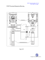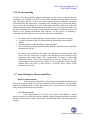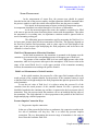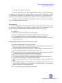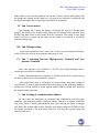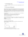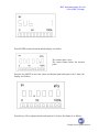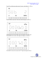
1
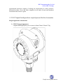
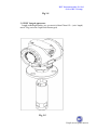
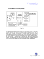
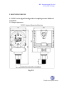
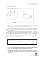
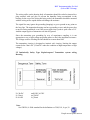
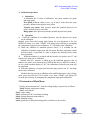
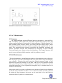
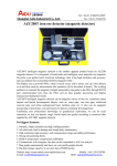
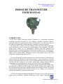
RLT Instrumentation Pvt Ltd (Unit of RLT Group) PRESSURE TRANSMITTER USER MANUAL INTRODUCTION 3351PT Series Digital. Intelligent pressure Transmitter is a multipurpose digitalized intelligent instrument developed by our company, including capacitance pressure transmitter and direct-coupled pressure/fluid level transmitter. It is made on the basis of the mature and dependable sensing technology, combining exchange technology. 16-bit single chip is adopted as its core element, with its powerful function and highspeed calculation capacity ensuring the excellent quality of the transmitter. The whole design frame focuses on its dependability, stability and high precision and intelligentization, meeting the growing demand in on-site industrial use. To get this goal, digitalized signal processing technology is used in the software to ensure its disturbance capacity and zero point stability. Meanwhile, it has the zero stability capacity (ZSC) and Temperature supplementing capacity (TSC). The powerful interface functions guarantees an excellent interactivity with no need of manual operator. Its digitalized meter head can display 3 physical parameter including pressure, temperature and current, and 0-100% analogue indications. Keystroke operation can finish the basic settings of zero transfer, range setting, damping setting under the circumstance of no standard pressure, greatly convenient for the onsite debugging. 3351PT series digitalized Pressures Transmitter has the optional HART module. After the transmitter is added the HART module, it has HART communication capacity, with the conventional operation being controlled with the general manual operator. The special communication equipment and software provided by our company can operator the marking and temperature supplementation actions. 3351PT series digitalized intelligent Pressures Transmitter can be widely used in the sectors such as petroleum, chemical, iron& steel, power supply, light industry and People are our prime movers RLT Instrumentation Pvt Ltd (Unit of RLT Group) environmental protection, capable of realizing the measurement of various pressures, differential pressure, flows and fluids, adaptable for all kinds of harsh and hazardous environment and corrosive agents. 1.2 3351PT digital. Intelligent direct-coupled pressure/fluid level transmitter Integral appearance and structure 1) 3351PT Integral appearance Length/width/height/quality (no accessories):98mm/78mm/152mm/0.75kg People are our prime movers RLT Instrumentation Pvt Ltd (Unit of RLT Group) Fig 1-4 2) 3351PT Integral appearance Length/width/height/quality (no accessories):98mm/78mm/131+ (wire length) mm/0.75kg (varied in weight for different types) Fig 1-5 People are our prime movers RLT Instrumentation Pvt Ltd (Unit of RLT Group) 1.2.2 Introduction to working principle Fig 1-6 As indicated in the working principle diagram fig.1-3, the outsides pressure or differential pressure will cause some changes in the sensor resistance value and the output value of bridge voltage. Through A/D conversion, it will change into the digital signal which is sent to the microprocessor for calculation; then a current control signal will be output to the current control circuit, converted into analogue 4-20 mA current output. Meanwhile, the microprocessor is responsible for the interactive and other actions (display and setting). The communication port used for digital communication needs the special port of our company. HART module will realize the transmitter HART communication. People are our prime movers RLT Instrumentation Pvt Ltd (Unit of RLT Group) 2. MOUNTING FOR USE 2.1 3351PT series digital. Intelligent direct-coupled pressure/ fluid level transmitter 2.2.1 Integral Appearance 3351PT Structure Dimensional Drawing Fig. 2-11 People are our prime movers RLT Instrumentation Pvt Ltd (Unit of RLT Group) 3351PT Structure Dimensional Drawing Fig. 2-12 People are our prime movers RLT Instrumentation Pvt Ltd (Unit of RLT Group) 2.2.2 On-site mounting 3351PT series direct-coupled pressure transmitter can be directly mounted onto the conduits by use of M20×1.5 or NPT1/2 outer screw, with the screwing moment no more than 30ft-1bs(or 40N.m); 3351PT series direct-coupled pressure transmitter can be put into the fluid for use, optional in 3 mounting ways including local, bracket and flange. Try to mount the transmitter in a place with small temperature difference, and avoid vibration and concussion. When mounting in an open air, try to keep the transmitter in a dry and ventilated place, avoid the strong sunshine and raining, which may result in the decline in the integral performance and longevity. In the process of mounting a transmitter, the following cases are required to take into consideration: Prevent the cable from getting direct contact with the strong corrosive agents Avoid the sediment or jam of residues inside the probe and pressure impulse conduit Pressure impulse conduit should be as short as possible The transmitter or pressure impulse conduit should be mounted a place with small temperature difference. In wiring of the transmitter the signal wire should not go through with other power wires the wiring pipe or groove, nor through the nearly position of the equipment with bigger power. The measurement of steam or other high temperature agents can be done through the process by cooling device. The measurement of steam agent may be done by way of getting the pressure impulse conduit filled with water or other fluids to avoid the direct contact of the transmitter with steam. 2.3 Issues Relating to Measurement Ways Fluid level measurement: In the measuring of fluid flow, the pressure tabs should be breached on the side of the process conduit to avoid the sediment of dregs. Meanwhile, the transmitter should be mounted beside or under the pressure tabs, to prevent the air bubbles from being discharged into the process conduit. Gas Measurement: In the measurement of gas flow, the pressure tabs should be opened breached at the top or side of the process conduit. And the transmitter should be mounted beside or on the process conduit, to make the collected fluids flow easily into the process conduit. People are our prime movers RLT Instrumentation Pvt Ltd (Unit of RLT Group) Steam Measurement: In the measurement of steam flow, the pressure taps should be opened breached on the side of the process conduit. And the transmitter should be mounted under the process conduit, to make the cooled collected fluid flow into the process conduit To be noted, in the measurement of steam or other high temperature agents, its temperature should not exceed the limited level for the use of transmitter. As for the measured agents like steam, the conduit is required to be filled with water to prevent the steam from being direct contact with the transmitter. Thus when the transmitter is in working state, its capacitance variation would be ignored with no need of mounting cooling pot. The differential pressure transmitter used for measuring the fluid level is a de facto static pressure head for the measurement of fluid bar. This pressure depends on the fluid level and the fluid proportion, with its value equal to the fluid height of the upper part of the pressure taps multiplying the fluid proportion, and irrelevant to the container’s volume or form. Fluid Level Measurement of Breached Container In this kind measurement, the transmitter is mounted at the bottom near the container so as to measure the corresponding pressure of the upper part of fluid level. The pressure of the container fluid level acts on the high-pressure side of the transmitter, while its low-pressure side open to the atmosphere. If the lowest value in the range of the tested fluids level is at the upper position of the transmitter mounting location, the transmitter must undergo the positive transfer. Fluid Level Measurement of Sealed Container In the sealed container, the pressure Po of the upper fluid container affects the tested pressure of the container bottom. So the pressure of the container bottom is equal to that the fluid level height multiples the fluid proportion then plus the pressure Po of the sealed container. To test the real value of fluid level, it is right to minus the pressure Po of the container from the tested pressure of the container bottom. For this, a pressure taps should be breached at the container top, and have it connected to the low-pressure side of transmitter. Thus, the pressure inside the container will act on both high and low sides of the transmitter. The result obtained is a direct proportion to the product of the fluid level height multiplying with fluid proportion. Pressure Impulse Connection Ways 1) Dry pressure impulse connection In the case of the gas on the fluid refuse to condensate, the connection conduit at the low side of transmitter will keep dry. This is so called Dry pressure impulse connection. The way determining the measure range of transmitter is the same to that of breached container fluid level. People are our prime movers RLT Instrumentation Pvt Ltd (Unit of RLT Group) 2) Wet pressure impulse connection In the case of the gas on the fluid getting condensate, there will be a gradual fluid accumulation inside the pressure conduit at the low-pressure side of transmitter, leading to an error on measurement. To avoid this error, certain fluid is filled into the lowpressure side of transmitter beforehand; this is called wet pressure impulse connection. The above situation will make the transmitter be with a head at the low-pressure side, so a negative transfer is needed. Decrease Error Pressure conduit makes transmitter connect with process technic conduit, and transfer the pressure at the pressure taps along the technic conduit to the transmitter. In the process of pressure transmission, the following reasons may cause the errors: 1) 2) 3) 4) 5) Leakiness; Abrasion loss (particularly in the use of detergent); Some gas existing in the fluid conduit (resulting in pressure head error); Accumulated fluid in the gas conduit (resulting in pressure head error ); Density difference caused by the time difference between conduits (resulting in pressure head error); The following ways can be used to decrease the errors: 1) Pressure conduit should be as short as possible; 2) When measuring fluids or steam, the pressure conduit should be connected up to the process technic conduit, with its rake less than 1/12; 3) For the measurement of gas, the pressure conduit should be connected down to the process technic conduit, with its rake not less than 1/12; 4) The layout of fluid pressure conduit should avoid an extruded point in the middle part, while the gas pressure conduit avoids the sunken part; 5) Both pressure conduit should keep in the same temperature; 6) To avoid the friction, the diameter of pressure conduit should be wide enough; 7) No gas is found in the pressure conduit filled with fluid; 8) When using isolating fluid, the fluids in both pressure conduits should be the same; 9) When using detergents, the connection part of detergent should be near to the pressure taps of technic pipe; the conduit way passed through by the detergent should be the same in length and diameter. Try to avoid detergent passing through the transmitter. People are our prime movers RLT Instrumentation Pvt Ltd (Unit of RLT Group) 2.4 Electrical Mounting System wiring mounting Fig 2-13 (Note 1: user can install the distributor or safe barriers per the onsite and design requirements. For details, see the usage of distributor and safe barrier) It is recommended to choose the explosion-proof impulse terminal with the cable diameter of φ 8-12. The connection terminal is set with test terminal, convenient for the online test of the operator. Signal terminal is situated in a separate housing of the electrical box. Screw up the meter cover for wiring. The upper end is for signal, while the lower end is for test meter. Fig.2-13 indicated the terminal location. The test terminal is used for connecting any optional indicator head or test. The power supply goes to the transmitter through the signal line, with no need of additional wiring. ! Special Attention: Do not connect the power signal line to the test terminal; otherwise the diode inside the test terminal would be destroyed. In case of the diode being damaged unfortunately, shortcutting the test terminal can keep the transmitter working on, except the indicator unable to connect. No need to shield the signal wire, and litz wire can be used for better effect. Do not lay together the signal wire and other power wires, to get near to the strong electricity equipment. People are our prime movers RLT Instrumentation Pvt Ltd (Unit of RLT Group) The wiring orifice on the housing body of transmitter should be sealed or inserted in a plug smeared with seal glue to prevent the humidity being accumulated in the housing. In the case of the wiring not being sealed, the transmitter should be mounted with the wiring orifice upside down to discharge the moisture. The signal line may ignore the grounding (hanging) or get to ground at any point on the loop line. The transmitter housing can have grounding or not, and the power has no need of being stabilized, even if the power ripples has a peak-to–peak value of 1V. And the output ripples of transmitter can also be ignored. Since the transmitter gets grounding by way of capacitance coupling, it is not appropriate to use a high-voltage mega-ohm meter to check the insulation resistance. The voltage used for checking the line should be no more than 100V The transmitter circuitry is designed as intrinsic safe circuitry, limiting the output current below 30mA DC (35mA DC under the condition of high temperature or high voltage). 2.5 Intrinsically Safety Type Explosion-proof Transmitter system wiring Drawing Ui: 28vDC Li: 30mA Pi: 0.84W um≥250V AC/DC uo≤28vDC lo≤30mA Note: See GB3836, 4-2000 standard for the definition n of UM, UO, lo, po, Ui People are our prime movers RLT Instrumentation Pvt Ltd (Unit of RLT Group) Li, pi. The connection wire or sable between safe barrier and transmitter has a largest allowed distribution capacitance of no more than 0.02uF, and the largest allowed distribution inductance of not more than 2.0mH. 3. Debugging and operation 3.1 Summary Instruction to Display: PV----- Transmitter in measurement state SV----- Transmitter in setting state Er------ Excessive pressure or sensor circuit fault mA----- signifies LCD display of output current value %------- signifies LCD display of percentage of measurement pressure corresponding to setting range ˚C------ signifies the average value of measurement agent and environment Temperature √------ signifies the output current of transmitter in square root state KPa----- signifies LCD display of pressure unit Mpa---- signifies LCD display of pressure unit 0 50 100% Signifies the analogue indication of pressure measurement corresponding to setting range S-PORT---- special communication port 3.1.2 Description of keys functions ESC MOVE ENTER DOWN UP : cancel the current operation and return to the previous operation : move cursor and decimal point in typing data : enter a menu and confirm an operation : As paging down a menu and inputting data, cursor position digital less 1 : As paging up a menu and inputting data, cursor position digital plus 1 People are our prime movers RLT Instrumentation Pvt Ltd (Unit of RLT Group) 3.1.3 Working state display PV Display: in measurement state SV Display: in setting state Er Display: signal circuit failure or pressure exceeded 3.1.4 Menu Description Menu is constructed in levels, and the maximum is 4 levels, as following: Rolling and selection of menu: Press the key UP, roll to display the items in ascending order Press the key DOWN, roll to display the items in descending order Press the key ENTER, enter the corresponding sub-menu or specific function operations Press the key ESC, return to the previous menu As indicate below UP SV Sub 0 DOWN UP SV Sub SV 1 DOWN Sub 2 People are our prime movers RLT Instrumentation Pvt Ltd (Unit of RLT Group) 3.1.5 Input symbols Use UP or DOWN to change the highest digital (the left-most one of the 6digit LED), and its loop order is 0…..9,-0……; the common digitals have the loop order as: 0…..9,-0…… 3.1.6 Input Integer When an integer is input, the screen displays XXXXXX, and the lowest digital flashes to indicate the cursor position. Press the key UP to increase 1 number of the cursor location Press the key DOWN to decrease 1 number of the cursor location When a negative number is input, the negative symbol is input at the location of the highest digital Press the key MOVE to move 1 digit to the left in cursor loop Press the key ESC to return without saving Press the key ENTER to save and return 3.1.7 Input signal When a decimal is input, the screen displays XXXXXX (depending on the decimal digital), and the decimal digital flashes to indicate the cursor position. Press the kef UP once and release to increase 1 number of the cursor location Press the kef DOWN once and release to decrease 1 number of the cursor location When a negative number is input, the negative symbol is input at the location of the highest digital Press the key MOVE to loop the cursor by 1 digital to the left, and decimal will follow the move Press the key ESC to return without a save Press the key ENTER to save and return Use UP and DOWN to change the highest decimal number and input the negative symbol 3.2 Accuracy Micro-tuning of Transmitter (Instruction: since the different of the standard and gravity acceleration may result in accuracy error of transmitter. User can do the output micro tuning through this operation to enhance its accuracy.) 1) Reset: press down the keys UP and DOWN at the same time for about 5 sec will reset the transmitter, and the program restarts. 2) Enter menu: press down ENTER for about 5 sec to enter main menu for the corresponding operations. People are our prime movers RLT Instrumentation Pvt Ltd (Unit of RLT Group) 3) Calibration operation: I. Instruction A transmitter has 3 values of calibration: zero point, transfer zero point and range point. Zero point: different value is zero, e.g. H and L rooms have the same pressure, defined as the physical zero points. Transfer zero point: 4mA pressure point (the possible physical zero point), defined as logic zero point. Range point: 4mA pressure point (the possible physical zero point). II. Operation Under the condition of no standard pressure, only the physical zero point can be calibrated. Method: press down the housing body button for zero alignment or the key DOWN for about 5 sec then “GOOD” will display after releasing it, prompting the completion of physical zero calibration, “0” will display after calibration. b) Under the condition of standard pressure source, it is available for the calibration of transfer range point and zero point. But these operations cannot be done usually. A password is a must to acquire the authority before doing these operations. When the authority is acquired and the transfer zero point is not “0”, the transfer zero point can be calibrated. Method: after the pressure is added up to the stabilized pressure value of transfer zero point, press down the key DOWN and the key MOVE for about 5 sec for a short moment display of “00”, the calibration of transfer zero point will be completed. When the authority is acquired and only the range point is not “0”, the range point can be calibrated. Method: after the pressure is added up to the stabilized pressure value of range point, press down the key UP for about 5 sec, then “GOOD” will display for seconds after releasing it, prompting the completion range point calibration. a) 3.3 Instruction of Main Menu Usually, the main menu has 7 items for rolling display, respectively as follows: Sub 0: display setting (unit setting) Sub 1: zero transfer Sub 2: range setting Sub 3: pressure port H, L terminals switching Sub 4: setting communications address Sub 5: damping setting Sub 6: password verifying and setting (after verification is successful) People are our prime movers RLT Instrumentation Pvt Ltd (Unit of RLT Group) After the password is input and verified, the menus will change to a rolling display of 14 items. A restart will go back to the 7-item menu. The first 6 items in the 14-item menus are the same to the above mentioned, and the rest items are respectively as follows: Sub 7: current parameters setting (R0, R100) Sub 8: P100 setting (maximum rating range) Sub 9: display or input differential pressure marking point Sub 10: mark differential pressure in room temperature Sub 11: reverse mark differential pressure in room temperature Sub 12: display or input temperature point Sub 13: display or input temperature compensation point In the state of main menu, no key operation for 2 min will return to the measurement state. 3.4 Detailed Instruction of sub-menu Operation I. Sub 0 display unit setting After entering sub 0 menu, the display will be the current measurement value and the corresponding unit; when the current is output in square root, it will display “√” unit optional menu, 6 items in rolling display are as follows in sequence: 0 kPa 1 MPa 2 mA 3% 4 √mA 5 ˚C Press the key UP and the above items will roll to display in ascending order. Press the key DOWN and the above items will roll to display in ascending order. Press the key ENTER will complete selection, and save into memorizer, then return to main menu. Press the key ESC will cancel the operation and the unit remains unchanged, then return to main menu. In the state of this menu with no key action for 2 min, the menu will return to the measurement state with unit remaining unchanged. People are our prime movers RLT Instrumentation Pvt Ltd (Unit of RLT Group) Note: output way of current dependent only on item 2 ands 4, and the other options will not change the original current output way. No square root function is configured with the digital-intelligent direct-coupled pressure/fluid level transmitter. II. Sub 1 zero transfer Upon entering sub 1 menus the display will prompt the input of a floating-point number. The display is the original setting. Input the zero transfer point (unit kPa), press ENTER and then return to main menu after this operation. The setting of zero point transfer will have no impact on the range, but the setting is not allowed to exceed the maximum rating range. III. Sub 2 Range setting Same to the operation of sub 1 menu, sub 2 is only used for setting the full-range, which is allowed to exceed the maximum rating range as well. IV. Sub 3 switching Between High-pressure Terminal and Low pressure Terminal Notes: this function is not available for 3351PT series Digital-intelligent directcoupled pressure/fluid level transmitter. Usually, differential pressure transmitter is defined with the H-L set upon leaving the factory, and the user is not permitted to change it. After entering this menu, it will display the current setting status and a change is not permitted. To reset it, input the password in sub 6 first to get the calibration authority, and then use UP and DOWN to set the options, and ENTER to confirm. ESC will keep the original setting and return. V. Sub 4 setting of communications address As more than one instrument are connected and communicate with the upper computer, each instrument must have different address. Otherwise, a response confliction may occur, failing to finish communications task. Upon entering this menu, an integral will display the original address point. Input the new address and press ENTER to finish the setting, and return to the main menu. Press ESC will keep the original setting and return to main menu People are our prime movers RLT Instrumentation Pvt Ltd (Unit of RLT Group) VI. Sub 5 Damping setting Same to the operation of sub4, sub5 is only used for setting damping value (0-32 sec or more). VII. Sub 6 password Management Upon entering sub 6 menu, the input an integral, the password, at the screen prompt, the program will verify whether or not the password is correct. If the input password is wrong, it will display “ERROR”, press ENTER will return to main menu. If the input password is the access password or user password, the menu system will be extended into 14-item menu, allowing more operations. Meanwhile, at this moment sub 6 will reset the user’s password. If a special password is input, and the corresponding function can be finished as described below: 040820: cancel transfer zero alignment and obtain calibration authority. 040821: cancel range calibration and obtain calibration authority. 050728: clear physical calibration Note: The operations in sub 7 through sub 13 are relating to the core parameters, and forbidden to use without the authority. This manual has no instruction on these operations. Examples for the operations: 1) Zero pint set as -5kpa (negative input) Pressure down the key ENTER for about5sec, and release it to enter main menu. The display is as follows: Press UP to roll the menu and repeat it once, the display is as follows: People are our prime movers RLT Instrumentation Pvt Ltd (Unit of RLT Group) Press ENTER to enter sub-menu and the display is as follow The current value is zero The cursor flashes before the decimal point. Press the key MOVE to move the cursor end decimal point and repeat it for 3 times, the display is as follows: Press the key UP to regulate number and repeat it for 5 times, the display is as follows: People are our prime movers RLT Instrumentation Pvt Ltd (Unit of RLT Group) Press the key MOVE to the move the cursor and decimal point and repeat it for once, the display is as follows: Press the key DOWN to input the negative symbol and repeat it for once, the display is as follows: Press the key MOVE to move the cursor and decimal point and repeat it for 5 times, the display is as follows: People are our prime movers RLT Instrumentation Pvt Ltd (Unit of RLT Group) Press ENTER to save the setting and return to main menu Press ESC to return to measurement state. 2) Range set as 7.2 kpa (decimal input) Press down ENTER for about 5 Sec and release it to enter main menu, the display is as follows: People are our prime movers RLT Instrumentation Pvt Ltd (Unit of RLT Group) Press UP to roll the menu and repeat it for twice, the display is as follows: Press ENTER to enter Sub 2 Sub-menu and the display is as follows: Display the previous value (8kpa), the cursor flashes at the units, digit Press DOWN once less the cursor digits, the display is as follows: Press MOVE to move the cursor to the 2nd digit in the right as follows: People are our prime movers RLT Instrumentation Pvt Ltd (Unit of RLT Group) Press UP to increase the cursor digits for a consecutive 2 times in the following display: Press MOVE to move the cursor to the 3rd digit in the right as follows: Press ENTER to save the setting and return to main-menu People are our prime movers RLT Instrumentation Pvt Ltd (Unit of RLT Group) Press ESC to enter the state of Measurement. 4. User’s Maintenance 4.1 Summary Our digital-intelligent pressure/differential pressure transmitter is smart and fixed, with zero stability capacity (ZSC) and Temperature supplementing capacity (TSC) plus seldom-regular maintenance. Functionally, a digital transmitter is largely comprised of 3 parts including sensor modules, master circuit board and meter head. Where: master circuit board is fastened with sensor modules with bolts, and coagulated with sol as a whole. This integrated design structure can stabilize the distributed capacitance and parasitic capacitance between them. Meanwhile, the decreasing of signal collecting circuit and signal source distance reduces the disturbance. This compact structure also provide a more solid and reliable transmitter with few problems occurred. 4.2 Soft Maintenance The digital transmitter is an intelligentized product with its parameters open to the users, who may adjust as per the actual situation the zero point, and set range and damping, even re-mark it. Likewise, this could cause the confused parameter setting or core parameter being modified resulting in a soft fault. In the case of core parameters (marked value upon leaving factory) being changed, it is necessary to re-mark it as per the operational instruction or reset the parameters through the way of communications, so as to make it work normally. In the actual need of zero point re-calibration, press downs the button for zero alignment on the side of the transmitter for about 5 sec to realize the manual operation. In need of the setting of other parameters, just screw up the meter head cover, and finish the operation with the keystrokes or communications. People are our prime movers RLT Instrumentation Pvt Ltd (Unit of RLT Group) 4.3 Hard Maintenance Generally, sensor modules, circuit board and meter head are not in the range of on-site repair. The hard fault maintenance item is only limited to circuit connection check, transmitter cleaning, changing meter head and wiring terminals check. Testing Terminals The testing terminals are connected with the both terminals of a diode, wit the loop signal power passing through inside. When the indicator head or testing equipment is connected with the testing terminals, the diode is shortcut. Except the voltage between both terminals less than the value voltage of the diode, no current would pass through the diode. In testing or connection the indicator head, to ensure no current passing through diode, the testing equipment or meter head should not have a resistance of no more than 10Ω(for 4-20mA DC model).the resistance value over the above value by3 times would generate an error of less than 1%. There are conductive copper components on the lower left side of “+”, and the lower right side of “-”, which can be used, in the electrified state of transmitter, to test the output current with a digital multi-meter. Meter Head check Screw up the meter head cover, release two M3 bolts with Philips screwdriver and take out the meter head; plug out the parallel wires and the power supply to dismantle the head. It is also the time to check to see if there is either any dirt or any problems with the line connection board. For any of the problems, deal with it in time. Reassembly of the meter head should be done in the reverse order of dismantling. Check main body of process sensor (capacitance sensor) pay attending to the following respects: 1. before the disassembly of the sensor main body, it is required to dismantle the transmitter from the working point. 2. After reassembly, it is required to undertake the cycling of the temperature and pressure to ensure its precision. This is included in the reassembly steps of process sensor main body. 3. Dismantle the 4 major bolts to dismantle the pressure room. 4. Use the soft cloth or mild detergent to clean the isolating diaphragm, and then wash it with water . 5. Pressure room can be rotated or assembled in reverse for convenience. Check wiring terminal Screw up the rear cover, the wiring terminals can be seen. Release the2 locating bolts to take down the wiring terminal cover, and the wiring circuit board is visible. Check to see if the board is visible. Check to see if the board is connected correctly and People are our prime movers RLT Instrumentation Pvt Ltd (Unit of RLT Group) reliably, pay a special attention to the assembly of feed through capacitors and testing diode. 4.4 Troubleshooting Symptom: over output Potential reasons and troubleshooting methods: Primary elements: check the range of the primary elements Pressure conduit: Check the state of leakage and jam If the cut-off valve is in full-open state Check the gas in the fluid conduit and fluid in the gas conduit. If the fluid proportion of conduit is changed. Check the dregs in the pressure room. Electrical connection of transmitter: confirm if the plug seat of parallel wires is clean. Test Electrical part: Check if the test display pressure valve has a bigger deviation with the actual pressure value .if yes, it is required to re-mark it or send back to factory for a proper treatment. Circuit check: if the display pressure value is consistent with the current. If not. The current is needed to re-regulate. Sensor module: see this section “check main body of process sensor” Power supply: check the out put of power supply Symptom: unstable output Potential reasons and troubleshooting methods: Parameter check: if the zero transfer and range setting are correct. Loop wiring: if the transmitter voltage is nominal. Check the intermittent shortcut. Open circuit and multiple grounding points. Tested agent pulse: regulate the damping value. Pressure conduit: check the gas in the fluid conduit and the fluid in the gas conduit. Electrical part test: check to see if the pressure value is stable through meter head, and then confirm if the instability is caused by sensor and circuit board. If yes, change the sensor and circuit board. Symptom: under-output or no output Potential reasons and troubleshooting methods: People are our prime movers RLT Instrumentation Pvt Ltd (Unit of RLT Group) Parameter check: if zero transfer and range setting are correct Primary elements: check elements assembly and working conditions. Any change of tested agent characteristic would affect input state. Loop wiring: if the transmitter voltage is a normal state. Check shortcut and multiple grounding points. If the polarity is right connected Check the loop impedance. Pressure conduit: if the pressure connection is correct. Check the state of leakage or jams. Check the gas in the fluid conduit Check the dregs in the pressure room. If the cut-of valve is full open and the balance valve is closed Check to see if the fluid density is changed in the pressure conduit. Electrical connection: if the sensor module wiring has a shortcut. Confirm if the parallel wires plug seat is clean. Check the wiring state of sensor module s. Check if the 8feet of the plug seat is correctly Connected to the housing. Diode fault test: change the diode or shortcut the testing terminals. Electrical fault of transmitter: use a stand by board to test if the circuit has a fault and change the faulted board. Sensor modules: see this section: check main body of process sensor”. 5. Instructions for Mounting and use of Flange-Type Transmitter 5.1 Summary Capacitance flange differential pressure/pressure transmitter is linked in a flange way with the tested part used for the following occasions: 1. It required isolate the high temperature agent from the transmitter; 2. The tested agent is corrosive to the sensitive elements of transmitter: 3. The tested agent is floating fluid or of high viscosity: 4. The tested agent is liable to solidified or crystallized due to the change of environment or process temperature; 5. The change of the tested agent needs to purify the testing head: 6. The testing head must keep clean. Capacitance flange differential pressure/pressure transmitter is manly used for continuously and precisely measure the fluid, gases and steams regarding to their different pressure and the fluid level, interface and density, etc. working with the throttling device, it is capable of continuously measure the flow of gases, fluids and People are our prime movers RLT Instrumentation Pvt Ltd (Unit of RLT Group) steams . And the tested signal can be converted into 4-20mA DC 2-wire system signals, which can be matched with other unit instruments or industrial control computers as the input signal of indication, recording and regulator to form the industrial automatic system for testing, recording and control. People are our prime movers