1
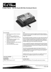
Installation & Quick Start Guide AIT2000 Class B AIS Transponder QUICK START AIT2000 - VR1.01 DIGITAL YACHT LTD AIT2000 Quick Start Guide 1. Introduction Congratulations on the purchase of your AIT2000 Class B AIS Transponder. It is recommended that your transponder is installed by a professional installer. This Quick Start Guide will provide basic information on the AIT2000 to allow you to install and get the AIT2000 working. The full User Manual for the AIT2000 is available to download on the Support section of our website www.digitalyacht.co.uk 2. Before you start You will need the following items and tools to complete the installation: Class B AIS Transponder. Dedicated VHF/AIS antenna and cable – not supplied Dedicated GPS antenna and cable - supplied Access to 12V or 24v DC power supply where the unit is to be installed. Four M4 screws or other fixings appropriate to the mounting location. To configure the unit you will need: ® ® A PC running Microsoft Windows XP / Windows Vista / Windows 7 or Mac OSX with a free USB port. proAIS2 Class B AIS Transponder configuration software – Windows and Mac versions of software are supplied on the latest Digital Yacht CD-ROM or available for download from the www.digitalyacht.co.uk website. An MMSI number for your vessel Note: You can obtain an MMSI (Maritime Mobile Service Identity) from the same authority that issues ship radio licences in your area. An MMSI may have already been provided with your existing VHF radio licence. The MMSI number used for the AIS Transponder should be the same as that programmed into your VHF DSC radio. If you do not have an MMSI number the AIS Transponder will operate in receive only mode. Do not enter an invalid MMSI number. 3. Installation Before starting installation select a suitable location for the AIS Class B Transponder. The unit is water resistant; however it should be installed below deck in a dry location. When locating the unit you should consider: Routing of power and antenna cables to the unit. Provision of sufficient space behind the unit for cable connections. Routing of data connections to PC or chart plotter from the unit. Maintaining the compass safe distance of 0.5m. Visibility of the front panel indicators. Installation Step 1 - Antennas Install the VHF/AIS antenna (not supplied) according to the hand book instructions supplied with the antenna. If you are going to share the boat’s existing VHF antenna i.e. use the antenna for both the VHF and AIS, you will need to install a suitable antenna splitter. It is very important that this splitter is suitable for use with an AIS Transponder as some of the lower cost splitters only switch one input and are only suitable for use with an AIS receiver. If you are in any doubt please contact [email protected]. The AIS antenna connector on the AIT2000 is a BNC type connector and it may be necessary to get a PL259 to BNC adaptor if you are connecting a normal VHF antenna to the AIT2000 as these are terminated in the standard PL259 VHF connector. DIGITAL YACHT LTD AIT2000 Quick Start Guide The supplied GPS antenna is designed to be fitted to a standard 1”x14 TPI threaded VHF pole mount, which are available in many different styles from all good marine electronic dealers and chandleries. You should ensure the GPS antenna has a good clear view of the entire sky. It is not recommended that the GPS antenna is mounted up a mast where the motion of the vessel will cause the antenna to swing and potentially reduce the accuracy of the GPS position. Do not mount your antenna in the direct path of a radar transmitter. Feed the ten metre long cable attached to the GPS antenna, through the pole and screw the antenna onto the pole mount as shown. Route the cable to your AIT2000 unit, adding any necessary extension cables. Connect the cable from the GPS antenna to the GPS connector on the AIT2000. The GPS antenna is terminated in a threaded TNC type connector to differentiate it from the AIS/VHF antenna which is terminated in a bayonet BNC type connector. Installation Step 2 – Mechanical Fixings Access to the fixing holes is achieved by removal of the two green decal strips down each side of the AIT2000. Once fixed in place, the green decal strips can be clicked back in place. Secure the AIS Transponder to a flat surface in the selected location. Use four M4 wood screws or other fixings suited to the material the unit is being fixed to. The unit may be installed in any orientation Fixing location drawing AIT2000 Quick Start Guide DIGITAL YACHT LTD Installation Step 3 - Power Provide power connections to the unit. Power is connected to the eight core PWR/DATA cable on the Red and Black wires. The Red wire is the positive (+) connection. The Black wire is the negative (-) connection. Connect the stripped wires to the nearest source of primary 12V or 24V DC power. Ensure that the supply is connected via the supplied 3A fuse or suitable circuit breaker. Add the fuse in the positive power connection to the unit if necessary. The AIT2000 Class B Transponder is designed for a 12V or 24v DC systems. Installation Step 4 – NMEA 0183 The AIT2000 can be connected to other AIS compatible equipment via the NMEA0183 connections on the PWR/DATA cable, via the NMEA 2000 interface cable and/or to a PC via the USB interface. The USB cable of the AIT2000 should be routed to the Boat’s PC to ensure that there is enough cable length. If you need to extend this cable, please use a USB extension cable that is no more than 4m in length. The maximum length of USB cable without the use of a powered extender cable or Hub is 5m. Please do not plug in the USB cable of the AIT2000 to your PC at this stage. We will cover this in section 4 Configuration. A table showing what each of the 12 wires of the PWR/DATA cable does is printed on the AIT2000 Transponder and repeated below for your convenience; Wire colour RED BLACK BLUE WHITE ORANGE BROWN TURQUOISE GREY PINK VIOLET YELLOW GREEN Description Power in + Power in Switch inputSwitch input+ NMEA0183 port 1 TX+ NMEA0183 port 1 TXNMEA0183 port 1 RX+ NMEA0183 port 1 RXNMEA0183 port 2 TX+ NMEA0183 port 2 TXNMEA0183 port 2 RX+ NMEA0183 port 2 RX- Function Power supply connections External switch connection for silent mode High speed NMEA0183 output (38,400 baud) intended for connection to chart plotters High speed NMEA0183 input (38,400 baud) Not normally used Low speed NMEA0183 Output (4,800baud) intended for connection to other NMEA0183 devices requiring a GPS feed. Note AIS data is not available on this output. Low speed NMEA0183 input (4,800baud) intended for connection to other NMEA0183 compatible sensors for multiplexing of data to the chart plotter The most common connection to a dedicated chart plotter is to take the NMEA Output 1 (Orange+ and Brown –) from the AIT2000 Transponder and to connect it to a free NMEA Input on the plotter. You must then tell the chart plotter that AIS data is connected to this port and set the baud rate to 38,400 Baud – the standard speed for AIS data. Consult the instruction manual supplied with your Chart Plotter to understand how this is configured. DIGITAL YACHT LTD AIT2000 Quick Start Guide The AIT2000 has a second NMEA 0183 output that can be used to pass GPS data to a VHF radio or instrument system. NMEA Output 2 transmits GPS data at 4800 baud – RMC, GGA and GGL sentences. NMEA 0183 data from other equipment can be connected to either of the NMEA Inputs of the AIT2000, although this is most commonly connected to NMEA Input 2 (Yellow+ and Green-) at the normal 4800 baud rate for NMEA 0183. This data is then multiplexed with the AIS data and output on the NMEA Output 1 at 38,400 baud and also on the USB – useful when connecting to equipment that only has one NMEA input or to a computer with limited USB ports. NOTE - Only NMEA messages with a valid checksum are passed through the AIT2000 and re-transmitted with the AIS data. Some older NMEA0183 equipment may not include checksums which were added in NMEA 0183 Version 2.0. Installation Step 5 – N2Net (NMEA2000) The AIT2000 also has an N2Net connection which is Digital Yacht’s NMEA2000 compliant interface. To connect to other NMEA2000 products, simply find or add a spare NMEA2000 “T” piece on the existing NMEA2000 network and connect the AIT2000 N2Net connector to the “T” piece. The N2Net cable is just over 1m long and is terminated in an NMEA2000 Micro Male Connector. The AIT2000 does not take any power from the NMEA2000 network The AIT2000 only outputs AIS data on to the network, it does not output any GPS data on to the network or provide any NMEA2000 to NMEA0183 conversion. Installation Step 6 – Remote Switch To connect a remote “Silent” switch that allows you to turn on/off the transmission of your own vessels position (good etiquette when moored or in congested but safe conditions), you will need a conventional toggle type switch (SPST), connected between the White and Blue wires. This can be mounted anywhere on the boat, thus allowing you to mount the AIT2000 below deck but having a switch in the cockpit or wheel house to control the Silent Mode operation. When the remote “Silent” switch is ON (closed) the AIT2000 will be in Silent mode (not transmitting) and when the switch is OFF (open) the AIT2000 will be in normal transmitting mode. Installation Step 7 Turn on the 12V or 24v power to the AIT2000 Verify that the green LED illuminates for a short period and then all four LED indicators on the front of the unit flash once, followed by illumination of the amber and red LED’s. Installation is now complete. The AIT2000 needs to be configured using the proAIS2 software – see next section. DIGITAL YACHT LTD AIT2000 Quick Start Guide 4. Configuration The AIT2000 transponder must be correctly configured for your vessel before operation. All configuration information must be entered carefully as this information will be transmitted to other AIS equipped vessels and shore stations. The AIS transponder is configured by connecting to a PC or Mac running the ‘proAIS2’ configuration tool supplied. For the purposes of programming, the AIT2000 can take sufficient power from the USB cable to communicate with the computer but not to operate as a Class B Transponder which requires an external 12v or 24v DC supply. This does mean that programming can be done at home or in the office by simply plugging the AIT2000 in to the USB port of your PC or Mac, without connecting the unit to a DC power supply. For Windows PCs, insert the supplied Digital Yacht Software CD-ROM and run the Setup.Exe program located in the “proAIS2 for AIT2000” folder. This installs both the USB drivers for the AIT2000 and the proAIS2 application. For Macs, insert the supplied Digital Yacht Software CD-ROM and install the “proAIS2.dmg” located in the “proAIS2 for AIT2000\Mac OSX” folder. This just installs proAIS2 as the drivers are already pre-installed on Macs. Plug in the AIT2000 USB cable in to your computer and then launch proAIS2. Select the COM port that the AIT2000 has been allocated by Windows or OSX. Click the ‘Connect’ button The computer will now query the AIT2000 and display any “Static” boat data stored in the unit. All new units will have no data stored and so you will just have a series of blank boxes in which you will need to enter your boat’s data (see below). 1. Enter Vessel Name, Call Sign and MMSI 2. Enter vessel dimensions and location of GPS antenna to the nearest metre. 3. Select the most appropriate vessel type. 4. Click “Write Configuration” to save the data to the AIT2000 5. Read the warning message carefully and proceed only if the MMSI number is correct. 6. Configuration of the AIS Class B Transponder is now complete *Note: For security reasons the MMSI can only be programmed once. Make sure you enter the correct number and double check when ProAIS2 warns you regarding MMSI programming. The MMSI can only be changed by returning the unit to your dealer. DIGITAL YACHT LTD AIT2000 Quick Start Guide 5. Operation Once installed and configured correct operation of the AIS transponder should be verified as follows: 1. Check that at least one of the LED's on the front of the unit is illuminated. If the red 'Error' LED is illuminated please refer to the troubleshooting section in the AIT2000 User Manual. 2. Check that the unit has a good GPS lock. If the GPS is locked the Latitude and Longitude will be displayed on the “GPS Status” tab in proAIS2 along with a number of green bars in the signal strength graph. 3. If the unit does not have GPS fix within a few minutes check your GPS antenna has a clear view of the sky, is to the correct specification and that the GPS antenna cable is connected. 4. Check that the Green 'Power' LED on the front of the unit illuminates. This will not happen until the unit has GPS fix and has transmitted its first position report. Please allow up to 5 minutes for this to occur. If the Green LED is illuminated you have successfully installed and configured the unit. The proAIS2 application can be closed and the PC disconnected from the unit. The unit requires only a power supply to operate. 5. If you are in an area with other AIS equipped vessels you can check the "Other vessels" tab in ProAIS2 to view position reports received from other ships. 6. Troubleshooting If the green LED is not illuminated after around 5 minutes then please check the following: 1. Is the MMSI number programmed? Check the “Diagnostics” tab in proAIS2. If there is a red cross next to the "AIS Transceiver MMSI Valid" item then you have not correctly configured the MMSI. 2. Does the unit have a GPS position fix? Check the “Diagnostics” tab in proAIS2. If there is a red cross next to the "GPS position fix" item then the unit does not have GPS fix. Check your GPS antenna and connections. 3. Is the unit reporting any alarms? Check the "Active alarms" area in the “Diagnostics” tab of ProAIS2 & refer to the troubleshooting guide at the back of the ProAIS2 user guide. 4. Is there an external power connection? When connected to a computer via USB, the AIT2000 can take enough power from the USB port to work as an AIS receiver but not as a Class B transponder. Occasionally if a fault occurs in the boat’s wiring, a fuse blows or the circuit breaker trips, then the AIT2000 will lose external power and only have the USB power. In these circumstances, the AIT2000 will receive AIS targets but not transmit its own position and the Red and Yellow LEDs will be lit. For more troubleshooting information on the AIT2000 transponder please consult Tech Note 00036-2012 in the Support section of www.digitalyacht.co.uk