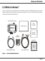
1
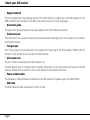
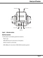
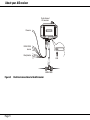
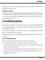
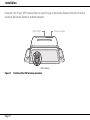
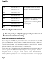
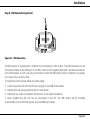
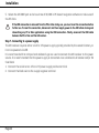
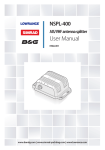
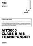
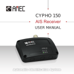
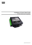
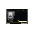
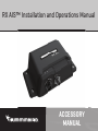
RX AIS™ Installation and Operations Manual
ACCESSORY
MANUAL
Thank you!
Thank you for choosing Humminbird®, the #1 name in marine electronics.
Humminbird has built its reputation by designing and manufacturing top quality,
thoroughly reliable marine equipment. Your Humminbird is designed for trouble-free
use in even the harshest marine environment. In the unlikely event that your
Humminbird does require repairs, we offer an exclusive Service Policy. For complete
details, see the separate warranty card included with your unit. We encourage you to
read this manual carefully in order to get the full benefit from all the features and
applications of your Humminbird product.
Contact Humminbird Customer Service at humminbird.com or call 1-800-633-1468.
Humminbird® is a registered trademark of Johnson Outdoors Marine Electronics, Inc.
NMEA 2000® is a registered trademark of the National Marine Electronics Association.
Table of contents
Table of figures
1
1.1
1.2
1.3
2
2.1
2.2
3
3.1
3.2
4
4.1
4.2
5
6
Figure 1
Figure 2
Figure 3
Figure 4
Figure 5
Figure 6
Figure 7
Figure 8
Table 1
Figure 9
Figure 19
Figure 11
Figure 12
Figure 13
Notices ......................................................................................... 1
Safety warnings......................................................................................... 1
Using the USB Connection ..................................................................... 2
General notices.......................................................................................... 2
About your AIS receiver .............................................................. 7
About AIS ..................................................................................................... 7
What's in the box?.................................................................................... 8
Installation ................................................................................12
Preparing for installation......................................................................12
Installation procedures .........................................................................14
Operation ...................................................................................25
Using the AIS receiver............................................................................25
Indicator functions .................................................................................26
Troubleshooting ........................................................................27
Specifications ...........................................................................28
Items included with the product....................................... 8
AIS receiver overview ......................................................... 10
Electrical connections to the AIS receiver .................. 11
Typical installation ............................................................. 12
AIS receiver dimensions ................................................... 15
AIS receiver mounting....................................................... 16
Position of the VHF antenna connector ...................... 17
Position of the Power and Data connector................. 18
Colour coding of wires in the accessory cable........... 19
Connecting to the NMEA 0183 data port .................... 20
NMEA 2000 Connection .................................................... 21
USB Connection .................................................................. 22
Connecting the power supply ......................................... 24
Indicator location on the AIS receiver unit.................. 26
Notices
1
Notices
!
When reading this manual please pay attention to warnings marked with the warning triangle shown
on the left. These are important messages for safety, installation, and usage of the product.
1.1 Safety warnings
!
This equipment must be installed in accordance with the instructions provided in this manual.
This equipment is intended as an aid to navigation and is not a replacement for proper navigational
judgement.
!
!
!
!
Page 1
This AIS receiver is an aid to navigation and must not be relied upon to provide accurate navigation
information. AIS is not a replacement for vigilant human lookouts and other navigation aids such as
RADAR. The performance of the AIS receiver may be seriously impaired if not installed as instructed in
the user manual, or due to other factors such as weather and/or nearby transmitting devices.
Compatibility with other systems may vary and is reliant on the third party systems recognizing the
standard outputs from the AIS receiver. The manufacturer reserves the right to update and change
these specifications at any time and without notice.
Do not install this equipment in a flammable atmosphere such as in an engine room or near to fuel
tanks.
This device should not be used as a navigational aid to prevent collision, grounding, vessel damage,
or personal injury. When the vessel is moving, water depth may change too quickly to allow time for
you to react. Always operate the vessel at very slow speeds if you suspect shallow water or
submerged objects.
Notices
1.2 Using the USB Connection
!
The USB port built into this product is not isolated from the vessel power supply, VHF antenna ground
or GPS Ground. Please observe the following procedures when connecting the USB port to avoid
grounding problems.
If the computer is permanently installed on the vessel and/or electrically connected to any other vessel
equipment, including power supplies, it is recommended that connection is made using the NMEA 0183
or NMEA 2000 interfaces. These benefit from being specifically designed for use in the marine
environment and provide isolated and robust communication between your devices.
If a battery powered laptop is being used, then it is recommended that you always switch off the
computer before connecting the USB cable.
1.3 General notices
Compass safe distance
The compass safe distance of this unit is 0.5m or greater for 0.3° deviation.
RF emissions notice
!
!
Warning! The AIS receiver generates and radiates radio frequency electromagnetic energy. This
equipment must be installed and operated according to the instructions contained in this manual.
Failure to do so can result in personal injury and/or AIS receiver malfunction.
Warning! The antenna should not be co-located or operated in conjunction with any other transmitting
antenna. The required antenna impedance is 50Ω.
Page 2
Notices
Warranty
The product is supplied with standard warranty as defined in the Warranty statement supplied with
the product.
!
Disassembly and repair of this electronic unit should only be performed by authorized service
personnel. Any modification of the serial number or attempt to repair the original equipment or
accessories by unauthorized individuals will void the warranty.
FCC Notice
NOTE: This equipment has been tested and found to comply with the limits for a Class B digital device,
pursuant to part 15 of the FCC Rules. These limits are designed to provide reasonable protection
against harmful interference in a residential installation.
This equipment generates, uses and can radiate radio frequency energy and, if not installed and used
in accordance with the instructions, may cause harmful interference to radio communications.
However, there is no guarantee that interference will not occur in a particular installation. If this
equipment does cause harmful interference to radio or television reception, which can be determined
by turning the equipment off and on, the user is encouraged to try to correct the interference by one
or more of the following measures:
- Reorient or relocate the receiving antenna.
- Increase the separation between the equipment and receiver.
- Connect the equipment into an outlet on a circuit different from that to which the receiver is
connected.
- Consult the dealer or an experienced radio/TV technician for help.
This device complies with part 15 of the FCC Rules. Operation is subject to the following two
conditions:
1. This device may not cause harmful interference, and
Page 3
Notices
2. This device must accept any interference received, including interference that may cause
undesired operation.
Industry Canada Notice
This device complies with Industry Canada licence-exempt RSS standard(s). Operation is subject to
the following two conditions:
1. This device may not cause interference, and
2. This device must accept any interference, including interference that may cause undesired
operation of the device.
This Class B digital apparatus complies with Canadian ICES-003.
Le présent appareil est conforme aux CNR d'Industrie Canada applicables aux appareils radio
exempts de licence. L'exploitation est autorisée aux deux conditions suivantes:
1. L'appareil ne doit pas produire de brouillage, et
2. L'utilisateur de l'appareil doit accepter tout brouillage radioélectrique subi, même si le brouillage
est susceptible d'en compromettre le fonctionnement.
Cet appareil numérique de la classe B est conforme à la norme NMB-003 du Canada.
Disposal of this product and packaging
Please dispose of the AIS receiver in accordance with the European WEEE Directive or with the
applicable local regulations for disposal of electrical equipment.
Every effort has been made to ensure the packaging for this product is recyclable. Please dispose of
the packaging in an environmentally friendly manner.
Accuracy of this manual
The AIS receiver may be upgraded from time to time, and future versions of the AIS receiver may
therefore not correspond exactly with this manual. Information in this manual is liable to change
Page 4
Notices
without notice. The manufacturer of this product disclaims any liability for consequences arising from
omissions or inaccuracies in this manual and any other documentation provided with this product.
This manual was written in English and may have been translated to another language.
Humminbird is not responsible for incorrect translations or discrepancies between documents.
ROHS Statement
Product designed and intended as a fixed installation or part of a system in a vessel may be
considered beyond the scope of Directive 2002/95/EC of the European Parliament and of the Council
of 27 January 2003 on the restriction of the use of certain hazardous substances in electrical and
electronic equipment.
Attention International Customers
Products sold in the U.S. are not intended for use in the international market. Humminbird
international units provide international features and are designed to meet country and regional
regulations. Languages, maps, time zones, units of measurement, and warranty are examples of
features that are customized for Humminbird international units purchased through our authorized
international distributors. To obtain a list of authorized international distributors, please visit our Web
site at humminbird.com or contact Humminbird Customer Service at (334) 687-6613.
Environmental Compliance Statement
It is the intention of Johnson Outdoors Marine Electronics, Inc. to be a responsible corporate citizen,
operating in compliance with known and applicable environmental regulations, and a good neighbor in
the communities where we make or sell our products.
WEEE Directive
EU Directive 2002/96/EC “Waste of Electrical and Electronic Equipment Directive (WEEE)” impacts
most distributors, sellers, and manufacturers of consumer electronics in the European Union. The
WEEE Directive requires the producer of consumer electronics to take responsibility for the
management of waste from their products to achieve environmentally responsible disposal during the
product life cycle.
Page 5
Notices
WEEE compliance may not be required in your location for electrical and electronic equipment (EEE),
nor may it be required for EEE designed and intended as fixed or temporary installation in
transportation vehicles such as automobiles, aircraft, and boats. In some European Union member
states, these vehicles are considered outside the scope of the Directive, and EEE for those
applications can be considered excluded from the WEEE Directive requirement.
This symbol (WEEE wheelie bin) on product indicates the product must not be disposed
of with other household refuse. It must be disposed of and collected for recycling and
recovery of waste EEE. Johnson Outdoors Marine Electronics, Inc. will mark all EEE
products in accordance with the WEEE Directive. It is our goal to comply in the collection,
treatment, recovery, and environmentally sound disposal of those products; however
these requirements do vary within European Union member states. For more
information about where you should dispose of your waste equipment for recycling and
recovery and/or your European Union member state requirements, please contact your dealer or
distributor from which your product was purchased.
Page 6
About your AIS receiver
2 About your AIS receiver
2.1 About AIS
The marine Automatic Identification System (AIS) is a location and vessel information reporting
system. It allows vessels equipped with AIS to automatically and dynamically share and regularly
update their position, speed, course and other information such as vessel identity with similarly
equipped vessels. Position is derived from the Global Positioning System (GPS) and communication
between vessels is by Very High Frequency (VHF) digital transmissions.
There are a number of types of AIS devices as follows:
• Class A transceivers. These are similar to class B transceivers, but are designed to be fitted to
large vessels such as cargo ships and large passenger vessels. Class A transceivers transmit at a
higher VHF signal power than class B transceivers and therefore can be received by more distant
vessels. They also transmit more frequently. Class A transceivers are mandatory on all vessels over
300 gross tonnes on international voyages and certain types of passenger vessels under SOLAS
regulations.
• Class B transceivers. Similar to class A transceivers in many ways, but are normally lower cost due
to the less stringent performance requirements. Class B transceivers transmit at a lower power
and at a lower reporting rate than class A transceivers.
• AIS base stations. AIS base stations are used by Vessel Traffic Systems to monitor and control the
transmissions of AIS transceivers.
• Aids to Navigation (AtoN) transceivers. AtoN’s are transceivers mounted on buoys or other
hazards to shipping which transmit details of their location to the surrounding vessels.
• AIS receivers. AIS receivers will generally receive transmissions from class A transceivers, class B
transceivers, AtoNs and AIS base stations but do not transmit any information about the vessel on
which they are installed.
This product is an AIS receiver.
Page 7
About your AIS receiver
2.2 What's in the box?
Figure 1 shows the items included with your AIS receiver purchase. The following sections give a brief
overview of each item. Please ensure all items are present, and if any of the items are not present,
contact Humminbird Customer Service.
Dual channel AIS receiver
Product manual
Quick
start guide
Warranty
information
Screws
(packet of 4)
Product CD
USB configuration cable
Figure 1
Power and data cable
Items included with the product
Page 8
About your AIS receiver
• Support tools CD
The CD supplied with the package contains the USB drivers to enable use of the AIS receiver via its
USB interface. Also included on the CD is the product manual in other languages.
• Quick start guide
The quick start guide provides a one page reference for the installation process.
• Product manual
This document is the product manual and should be read thoroughly prior to any attempt to install or
use the AIS receiver.
• Fixing screws
Four fixing screws are provided with the product for mounting of the AIS receiver. Please refer to
Section 3.2 for details of how to mount the AIS receiver.
• AIS receiver unit
Figure 2 shows an overview of the AIS receiver unit.
The AIS receiver has an indicator which provides information to the user about the status of the AIS
receiver. Please refer to Section 4.2 for more details of the indicator functions.
• Power and data cable
The accessory cable provides connections to the AIS receiver for power supply and NMEA 0183.
• USB cable
The USB cable provides connections to a PC or Mac.
Page 9
About your AIS receiver
.
Indicator lights
VHF antenna
Mounting
holes
Mounting
holes
Power and data
Access to USB connector
NMEA 2000
Figure 2
AIS receiver overview
Electrical connections
The AIS receiver has the following electrical connections:
• Power supply
• NMEA 0183 data port for connection to chartplotters
• USB for connection to a PC or Mac
• NMEA 2000 port for connection to NMEA 2000 compatible equipment
Page 10
About your AIS receiver
Dual channel
AIS receiver
Power in
NMEA 0183
device
Chartplotter
USB
NMEA 2000
Figure 3
Page 11
Electrical connections to the AIS receiver
Installation
3 Installation
3.1 Preparing for installation
Figure 4 shows a typical installation configuration for the AIS receiver. Please take the time to
familiarise yourself with the system elements and their connections prior to attempting installation.
Chartplotter
VHF antenna
Dual channel
AIS receiver
Power in
USB
NMEA 0183 device
NMEA 2000
Figure 4
Typical installation
Page 12
Installation
In addition to the items provided with your AIS receiver, the following items will be required for
installation:
VHF antenna
Connection to a suitable VHF antenna will be required for the AIS receiver to operate. A standard
marine band VHF antenna such as that used with VHF voice radios will be sufficient. Please take note
of the warnings in Section 1 regarding the use of antennas.
Alternatively, if you wish to use an existing VHF antenna, antenna splitter products are available which
allow the existing antenna to be used with two radio devices, such as a VHF voice radio and the AIS
receiver.
Antenna cables
Please check that the VHF antenna you intend to use has sufficient cable to reach between the VHF
antenna and the AIS receiver unit. If it is not sufficient you will need an extension cable. Please contact
Humminbird Customer Service for details of suitable products. For reference the VHF antenna
connector type on the AIS receiver unit is SO239, and it is intended to mate with a PL259 connector.
Power and data cables
The AIS receiver unit is supplied with a two meter long power and data cable, and the AIS receiver unit
is supplied with a two meter long power and data cable. If you require longer cables to reach your
power supply, please ensure the cables are capable of carrying an average current of up to 200mA.
Means of connecting the cables together will also be required. The use of ScotchlokTM connectors is
recommended for this purpose.
Chartplotter
To display received AIS position reports as other vessels on your chartplotter, you will need to connect
your AIS receiver to your chartplotter. Please refer to the user manual supplied with your chartplotter
for details of how to connect and configure your chartplotter for use with AIS devices. For general
guidance your chartplotter should be configured to accept NMEA data at 38400 baud (sometimes
Page 13
Installation
referred to as 'NMEA HS' in the plotter configuration menu). You may also need to enable the display
of AIS targets in the chart options.
Connection to a PC or Mac
If you choose to use a PC or Mac with suitable charting software to display received AIS messages as
other vessels, this can be accomplished by connecting the USB connector directly to the PC or Mac.
Your PC may require USB software drivers to connect to the AIS receiver and these can be found on
the CD included with the product.
3.2 Installation procedures
Before beginning installation of your AIS receiver, please ensure you have the necessary additional
items as detailed in Section 3.1. It is strongly recommended that you read all of the instructions in
this manual prior to installation.
If after reading this manual you are unsure about any element of the installation process, please
contact Humminbird Customer Service for advice.
The following sections explain the installation process step by step for each of the main elements of
the system.
Step 1 - Installing the AIS receiver
Please note the following guidelines when selecting a location for your AIS receiver:
• The AIS receiver must be fitted in a location where it is at least 0.5m from a compass.
• There should be adequate space around the AIS receiver for routing of cables. See Figure 5 for
details of the AIS receiver dimensions.
• The ambient temperature around the AIS receiver should be maintained between -25°C and +55°C.
• The AIS receiver should not be located in a flammable or hazardous atmosphere such as in an
engine room or near to fuel tanks.
Page 14
Installation
• The AIS receiver is fully waterproof to ingress protection rating IPx6, however it is recommended
that the AIS receiver is not subjected to extended periods of exposure to spray or submersion.
• It is recommended that the AIS receiver is installed in a 'below decks' environment.
• It is acceptable to mount the AIS receiver either vertically or horizontally.
• The product is supplied with four self tapping screws for attachment of the AIS receiver to a
suitable surface. Please refer to Figure 6 for guidance.
• The AIS receiver should be mounted in a location where the indicator is readily visible as this
provides important information on the status of the AIS receiver.
57 mm
175 mm
Figure 5
Page 15
AIS receiver dimensions
48 mm
100 mm
152 mm
Installation
Figure 6
AIS receiver mounting
Step 2 - Connecting the VHF antenna
1 Route the cable from the VHF antenna to the AIS receiver, and connect it to the VHF connector on
the AIS receiver as shown in Figure 7.
A standard marine band VHF antenna or AIS antenna should be used with the AIS receiver. The
connector type on the AIS receiver is SO239. Your chosen VHF antenna requires a PL259 connector to
Page 16
Installation
mate with this. If your VHF antenna does not use this type of connector, please contact Humminbird
Customer Service for details of available adaptors.
NMEA 2000
VHF antenna
Figure 7
Page 17
Position of the VHF antenna connector
Power and data
Installation
Step 3 - Connecting the accessory cable
VHF antenna
Power and data
Figure 8
NMEA 2000
Position of the Power and Data connector
An accessory cable is supplied with the product to provide connections to power and the NMEA 0183
data ports. The cable has a pre-moulded connector at one end, which should be connected to the
connector on the unit marked 'PWR/DATA'. The other end of the cable has twelve colour coded bare
wires ready for connection. Table 1 lists the function of each colour coded wire for reference.
Wire colour
Description
Function
Red
Power in +
Power supply connections
Black
Power in -
Light Green
Not used
Orange
Not used
No connection
Page 18
Installation
Brown
NMEA 0183 port 1 TX+
Blue
NMEA 0183 port 1 TX-
White
NMEA 0183 port 1 RX+
Green
NMEA 0183 port 1 RX-
Purple
NMEA 0183 port 2 TX+
Pink
NMEA 0183 port 2 TX-
Grey
NMEA 0183 port 2 RX+
Yellow
NMEA 0183 port 2 RX-
Table 1
!
High speed NMEA 0183 port (38,400baud)
intended for connection to chartplotters
Low speed NMEA port (4,800baud) intended
for connection to other NMEA 0183
compatible sensors for multiplexing of data
to the chartplotter
Colour coding of wires in the accessory cable
Please check your wiring very carefully before applying power to the product. Failure to wire the
product correctly could result in permanent damage.
Step 4 - Connecting to NMEA 0183 compatible equipment
The two independent NMEA 0183 data ports provide connection to your chartplotter and other NMEA
0183 compatible equipment. Each port consists of two wires colour coded as shown in Table 1 and in
Figure 9. Connect the wires to the appropriate connections on your NMEA 0183 compatible
equipment. Please refer to your equipment manual for more information.
The AIS receiver has a high speed output port which operates at 38,400baud and a low speed input
port which operates at 4,800baud. The high speed port is intended primarily to connect to a
chartplotter, while the low speed port is intended to connect to other NMEA 0183 devices. A
multiplexing feature is provided, which means any messages that are received via the low speed port
Page 19
Installation
are automatically transmitted via the high speed port. This is particularly useful when using a
chartplotter having only a single NMEA 0183 port. As any other sensor (such as a gyro-compass) can
be connected to the AIS receiver via the low speed port, and the AIS receiver can be connected via the
high speed port to the chartplotter resulting in the chartplotter receiving both AIS information and
heading information simultaneously. Configure your equipment to the correct baud rate. The baud
rate is determined by the port you’ve chosen for connection.
Red
Black
Light green
Orange
Power in +
Power in –
Not used
Not used
Brown
Blue
White
Green
Purple
Pink
Grey
Yellow
Figure 9
Transmit +
Transmit –
Receive +
Receive –
Transmit +
Transmit –
Receive +
Receive –
NMEA 0183
Port 1
38,400baud
(chartplotter)
NMEA 0183
Port 2
4,800baud
(other NMEA 0183 device)
Connecting to the NMEA 0183 data port
Page 20
Installation
Step 5 - Connection to an NMEA 2000 network (optional)
VHF antenna
Power and data
NMEA 2000
Figure 10 NMEA 2000 Connection
The AIS receiver can be connected to an NMEA 2000 network by a suitable NMEA 2000 network cable
available from your local dealer. If your vessel has an NMEA 2000 network, please refer to the relevant
documentation for your NMEA 2000 equipment. Once connected, and with your chartplotter also
connected to your NMEA 2000 network, you can receive AIS targets on your chartplotter.
Page 21
Installation
Step 6 - USB Connection (optional)
Figure 11 USB Connection
The AIS receiver is supplied with a USB port for connection to a PC or Mac. The USB connector can be
connected directly to the USB port on the PC or Mac via the supplied USB cable. To enable connection
of the AIS receiver to a PC, use the product CD to install the USB drivers. Driver installation is typically
not required for use with a Mac.
To install the drivers please follow the steps below:
1. Insert the product CD into the PC and navigate to the USB drivers folder.
2. Double click the setup.exe file to launch the installer.
3. Follow the on-screen installation instructions to complete installation.
4. Once installed the AIS unit can be connected to the PC. The USB drivers will be installed
automatically, and the AIS will appear as a new COM port device.
Page 22
Installation
5. Select the AIS COM port and a baud rate of 38,400 in PC based navigation software to make use of
the AIS data.
!
If the USB connection is removed from the PC or Mac during use, you must reset the connection before
further use. To reset the connection, disconnect and then reapply power to the AIS before closing and
relaunching any PC or Mac applications using the USB connection. Finally, reconnect the USB cable
between the PC or Mac and the AIS receiver.
Step 7 - Connecting to a power supply
The AIS receiver requires either a 12V or 24V power supply typically provided by the vessel's battery, or
it can be powered via USB.
It is recommended that crimped and soldered lugs are used to connect the AIS receiver to the power
source. It is recommended that the power supply is connected via a suitable circuit breaker and/or 3A
fuse block.
1. Connect the red wire to a 12V or 24V power supply positive terminal.
2. Connect the black wire to the supply negative terminal.
Page 23
Installation
Indicator lights
Power
(Green)
Red
AIS messagePower
received
in +
Black
(Amber)
Power in –
Light green
Orange
Not used
Not used
Brown
Blue
White
Green
Purple
Pink
Grey
Yellow
Transmit +
Transmit –
Receive +
Receive –
Transmit +
Transmit –
Receive +
Receive –
NMEA 0183
Port 1
38,400baud
(chartplotter)
NMEA 0183
Port 2
4,800baud
(other NMEA 0183 device)
Figure 12 Connecting the power supply
Page 24
Operation
4 Operation
4.1 Using the AIS receiver
Once the unit has been installed, it is ready for use. Providing other vessels with AIS transceivers
installed are within radio range of your vessel, you should see their details appear on your chartplotter
or PC.
Specific details of how to configure your chartplotter to make use of the AIS receiver features will be
provided in your chartplotter manual. If you are using charting software running on a PC, please refer
to the instructions provided with your chart plotting software to configure it and display AIS
information.
Page 25
Operation
4.2 Indicator functions
The AIS receiver includes a green power indicator light and an amber AIS reception indicator light as
shown in Figure 13. The green indicator will illuminate when power is applied, and the amber indicator
will flash on receipt of AIS messages.
Indicator lights
Power
(Green)
AIS message received
(Amber)
Figure 13 Indicator location on the AIS receiver unit
Page 26
Troubleshooting
5
Troubleshooting
Issue
Possible cause and remedy
No data is being received by the
chartplotter
• Confirm that the power supply is connected correctly.
• Confirm that the connections to the chartplotter are
correct.
• Confirm that the VHF antenna is correctly connected in
accordance with the instructions in the manual.
The power
illuminated
• Confirm that the power supply is connected correctly.
indicator
is
not
The reception indicator is flashing
but AIS targets are not displayed
on the chartplotter
• Confirm the chartplotter NMEA port configuration is set to
receive AIS data.
• Confirm the chartplotter display settings are configured to
show AIS targets.
• Consult the chartplotter manufacturers documentation.
The power indicator is illuminated
but the reception indicator is not
flashing to indicate receipt of AIS
messages
• Confirm there are vessels equipped with AIS transceivers in
your area.
• Confirm the VHF antenna is correctly installed and
connected.
If the guidance given in the table above does not rectify the problem you are experiencing, please
contact your dealer for further assistance.
Page 27
Specifications
6
Specifications
Parameter
Value
Dimensions
175 x 100 x 48 mm (L x W x H)
Weight
250g (AIS receiver unit only)
Power
DC (9.6 - 31.2V) or USB powered
Average power consumption <1W
Current consumption <200mA at 12VDC
Electrical interfaces
USB
NMEA 0183 38,400 baud output
NMEA 0183 4,800 baud input
NMEA 2000 LEN=1
Connectors
VHF antenna connector (SO-239)
USB type mini B connector
NMEA 2000 standard connector
12 way power input / NMEA 0183
Dual channel receiver
Fixed frequency reception at 161.975MHz and 162.025MHz
Channel Bandwidth
25kHz
Receiver Sensitivity
Better than -112dBm at 20% Packet Error Rate
Environmental
Operating temperature: -25ºC to +55ºC
Page 28
Specifications
Ingress Protection rating
!
IPx6
Product specifications and features are subject to change without notice.
Power supply information for this product can be found on the ratings label which is fitted on the
bottom case of the Humminbird Receiver.
Page 29
CONTACT HUMMINBIRD
Contact Humminbird Customer Service in any of the following ways:
Web site:
humminbird.com
E-mail:
[email protected]
Telephone:
1-800-633-1468
Direct Shipping:
Humminbird
Service Department
678 Humminbird Lane
Eufaula, AL 36027 USA
Hours of Operation:
Monday - Friday
8:00 a.m. to 4:30 p.m. [Central Standard Time]
201-0423:2