1
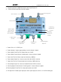
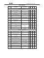
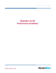
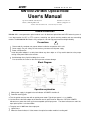
MN1000-2W Mini Optical Node
MN1000-2W Mini Optical Node
User’s Manual
QUALITY FIBER AND RF, INC
HTTP://WWW.QFRF.COM
Address: 8941 SE Duncan St
PHONE:772-545-9757
EMAIL: [email protected]
Hobe Sound, FL 33455
General Introduction
MN1000-2W is a next-generation optical node for use in bi-directional optical fiber and CATV network systems. It
is an ideal terminal for HFC or FTTx systems, containing one optical receiving module and one transmitting
module. The MN1000-2W Mini Node is very compact in size with high performance and high reliability.
Precautions
、
、
、
!
1 Please read this complete user manual before installation or operation of this unit.
2 Power supply: For your safety, DO not touch any connector end of power supply
3 Power cord protection
Install the power adapter in a safe place without any other object on it. Pay careful attention to the proper
routing of the power cable to the receiver.
4 Avoid leakage of any liquid, including rain or snow.
Do not remove the screws on the shell to prevent moisture damage.
、
Block Diagram
Operation explanation
、
、
1 When power supply is plugged in the red indicator of POWER should be lit.
2 Downlink receiving parts
a. Test the optical receive power with an optical power meter. Typical input power is -1 to +2.0dBm.
b. Connect fiber to the fiber adapter at the downlink end of optical receiver. When the "OPTICAL POWER"
indicator turns green that shows you have acceptable optical input power. The alarm indicator turns red if the
input optical power is over than 2dBm.
c. Testpoint level is 20dB lower than output port.
3 Uplink Parts
a. When the Green Indicator is lit that means the optical transmitter module is working well.
、
:
MN1000-2W Mini Optical Node
b. Ensure that the Return RF Drive level is no more than 15dBmV.
c. Testpoint signal level is 20dB lower than the return signal input port.
d. Connect the return path fiber to the fiber adapter.
11. RF Output Port
1.Power In Port
2.Power Indicator
10. Receiving
Optical Power
Test Port
3.Return Optical
Power Test Port
9.Receiving
Optical Power
Indicator
4. Return Optical
Power Indicator
5. Return Level
Test Port
6. Return Optical
Output Port
7. Output Level
Test Port
8. Forward Optical
Input Port
1. Power In Port: +12~15V DC input
:
2. Power Indicator If power supply feeding is normal, indicator is lighted.
3. Return Optical Power Test Port: Output power test, 1V/mW
4. Return Optical Power Indicator: If output power is normal, indicator is lighted.
5. Return Level Test Port: Return input level monitoring, -20dB test
6. Return Optical Output Port: Connect to return fiber with SC/APC connector
7. Output Level Test Port: Forward output level monitoring, -20dB monitoring
8. Forward Optical Input Port: Connect to forward fiber with SC/APC connector
9. Receiving Optical Power Indicator: If receiving power is normal, indicator is lighted.
10. Receiving Optical Power Test Port: Input optical power test,1V/mW
11. RF Output Port: Forward signal output port, return signal input port as well as +12~15V DC feeding port
MN1000-2W Mini Optical Node
Specifications
SYMBOL
PARAMETER
CONDITIONS
MIN
TYP
MAX
UNIT
1600
nm
Downstream Receiver
λ
Optical wavelength
1290
Vopt.in
Test voltage
λ=1310
Pin
Optical input power
continuous
F
Frequency range (option)
FL
Flatness of frequency response
S22
Lo
1
0.25
1
54
f=54 to 1000MHz
V/mW
2
mW
1000 MHz
±0.5
dB
Output return loss
16
dB
Output level
25
dBmV
Optical input return losses
CTB
CTB
CSO
CSO
f
Equivalent input noise
45
77 NTSC channel
loading,
dB
61
68
dB
60
63
dB
f=55MHz
7
pA/Hz
Upstream FP Transmitter
λ
Optical wavelength
1290 1310 1330
Wout
Optical output power
Vopt.in
Test voltage
LRin
RF input level
F
Frequency range (option)
FL
Flatness of frequency response
f=5 to 42MHz
±0.5
dB
S11
Input return loss
f=5 to 42MHz
16
dB
0.5
λ=1310
Total current consumption (DC)
Tmb
Operating temperature range
2
V/mW
15
dBmV
42
45
V+=8V
MHz
dB
330
-20
mW
1
5
Optical output return loss
Itot
1
nm
mA
+65
℃