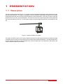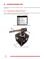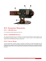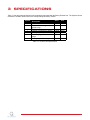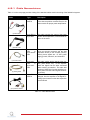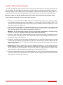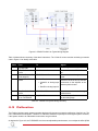
1
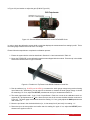
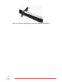
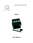
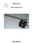
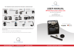
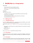
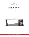
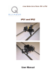
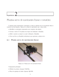
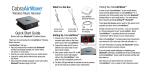
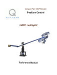
Quanser Flexible Link
User Manual
FLEXGAGE
Quanser Inc.
2011
c 2011 Quanser Inc., All rights reserved.
⃝
Quanser Inc.
119 Spy Court
Markham, Ontario
L3R 5H6
Canada
[email protected]
Phone: 1-905-940-3575
Fax: 1-905-940-3576
Printed in Markham, Ontario.
For more information on the solutions Quanser Inc. offers, please visit the web site at:
http://www.quanser.com
This document and the software described in it are provided subject to a license agreement. Neither the software nor this document may be
used or copied except as specified under the terms of that license agreement. All rights are reserved and no part may be reproduced, stored in
a retrieval system or transmitted in any form or by any means, electronic, mechanical, photocopying, recording, or otherwise, without the prior
written permission of Quanser Inc.
FLEXGAGE User Manual
2
CONTENTS
1
Presentation
1.1
Description
4
4
2
Components
2.1
Component Nomenclature
2.2
Component Description
5
5
6
3
Specifications
7
4
System Setup
4.1
Assembly
4.2
Wiring Procedure
4.3
Calibration
8
8
8
11
5
Testing and Troubleshooting
5.1
SRV02 Motor and Sensors
5.2
Strain Gauge Sensor
14
14
14
6
Technical Support
16
FLEXGAGE User Manual
v 1.0
1
PRESENTATION
1.1 Description
The rotary flexible link depicted in Figure 1.1, consists of a strain gauge which is mounted at the clamped end of a thin
stainless steel flexible link. The system is designed to mount on a Quanser SRV02 plant resulting in a horizontally
rotating flexible link that can be used to perform flexible link control experiments. A DC motor is used to rotate the
flexible link from one end in the horizontal plane. The motor end of the link is instrumented with a strain gauge that
can detect the deflection of the tip. The final system output is an analog signal proportional to the deflection of the
link.
Figure 1.1: Quanser Flexible Link System
This system is similar in nature to the control problems encountered in large light space structures where the weight
constraints result in flexible structures that must be controlled using feedback techniques. The rotary flexible link is
an ideal experiment intended to model a flexible link on a robot or spacecraft. This experiment is also useful in the
study of vibration analysis and resonance.
FLEXGAGE User Manual
4
2
COMPONENTS
The rotary flexible link components are identified in Section 2.1. Some of the those components are then described
in Section 2.2.
2.1 Component Nomenclature
The main components of the rotary flexible link system are listed below in Table 2.1, and labeled in Figure 2.1 and
Figure 2.2. Please use the ID # to locate each component in the figures below.
ID
1
2
3
4
5
6
7
8
9
Component
SRV02 Plant
FLEXGAGE Module
FLEXGAGE Link
Strain Gauge
Strain Gauge Circuit
Thumbscrews
Sensor Connector
OFFSET Potentiometer
GAIN Potentiometer
Table 2.1: Listing of Rotary Flexible Link Components
Figure 2.1: FLEXGAGE Coupled to SRV02
FLEXGAGE User Manual
v 1.0
Figure 2.2: Strain Gauge Closeup
2.2 Component Description
2.2.1 SRV02 Plant
For more details about SRV02 plant please refer to [2].
2.2.2 FLEXGAGE Module
This component is depicted in Figure 2.1 with ID #2, and consists of the FLEXGAGE Link (ID #3 in Figure 2.2), the
strain gauge, the strain gauge circuitry, and a sensor connector. As shown in Figure 2.2, the FLEXGAGE module
simply mounts onto the SRV02 plant using two thumbscrews.
2.2.3 Strain Gauge
The strain gauge sensor is depicted in Figure 2.2 with ID #4, and produces an analog signal proportional to the
deflection of the tip. There are two potentiometers available on the strain gauge circuitry. The OFFSET and GAIN
potentiometers are depicted in Figure 2.2 by ID #'s 8 and 9 respectively and are used in the calibration process of
the flexible link system. Section 4.3 of this document includes instructions on using these potentiometers to calibrate
the system.
FLEXGAGE User Manual
6
3
SPECIFICATIONS
Table 3.1 lists and characterizes the main parameters associated with the Rotary Flexible Link. The Symbol column
denotes the variable names used in the corresponding laboratory manual.
Symbol
Ll
ml
Jl
Description
Module Dimensions
Flexible Link Length (strain
gauge to tip)
Flexible Link Mass
Flexible Link Moment of Intertia
Strain gauge bias power
Strain gauge measurement
range
Strain gauge calibration gain
Value
Unit
48 x 2
41.9
cm2
cm
0.065
0.0038
±12
±5
kg
kg.m2
V
V
1/16.5
rad/V
Table 3.1: Flexible Link specifications
FLEXGAGE User Manual
v 1.0
4
SYSTEM SETUP
See Section 4.1 for instructions on how to to put the rotary flexible link plant together. Once the plant is setup, you
can refer to Section 4.2 for the wiring instructions and finally calibrate the system using the instructions provided in
Section 4.3 before performing laboratories.
4.1 Assembly
Setting up the flexible link system is fairly simple. Please follow the procedure below to setup the flexible link module
for experimental use. Wiring instructions are provided in Section 4.2 of this document.
1. Before beginning, ensure the SRV02 is setup in the high-gear configuration as detailed in [2].
2. Place the FLEXGAGE module (ID #2 in Figure 2.1) on the load shaft of the SRV02 plant.
3. Secure the FLEXGAGE in place by tightening the two supplied thumbscrews. The final configuration of the
FLEXGAGE module after being mounted to the SRV02 plant should resemble Figure 4.1.
Figure 4.1: Mounting the FLEXGAGE onto the SRV02
4.2 Wiring Procedure
The following is a listing of the hardware components used in this experiment:
• Power Amplifier: Quanser Amplifier (e.g., VoltPaq).
• Data Acquisition Board: Quanser DAQ (eg. QPID or Q2-USB).
• Flexible Link Plant: Quanser FLEXGAGE Module.
• Rotary Servo Plant: Quanser SRV02, SRV02-T, SRV02-E, SRV02-EHR, or SRV02-ET.
In addition to the above listed components a calibration stand and comb as well as the required cables are also
supplied with the system. Section 4.2.1 provides a listing of the cables supplied with the system and Section 4.2.2
will provide instructions for properly wiring the rotary flexible link module.
FLEXGAGE User Manual
8
4.2.1 Cable Nomenclature
Table 4.1 on the next page provides a listing of the standard cables used in the wiring of the flexible link system.
Cable
Type
2xRCA
2xRCA
to
Description
This cable connects an analog output channel
of the data acquisition terminal board to the
power module for proper power amplification.
(a) RCA Cable
4-pin-DIN to
6-pin-DIN
This cable connects the output of the power
module, after amplification, to the desired DC
motor on the servo.
5-pin-stereoDIN
to
5-pin-stereoDIN
This cable carries the encoder signals between an encoder connector and the data
acquisition board (to the encoder counter).
Namely, these signals are: +5 VDC power
supply, ground, channel A, and channel B
6-pin-miniDIN
to
6-pin-miniDIN
This cable carries analog signals (from joystick, plant sensor, etc.) to the amplifier,
where the signals can be either monitored
and/or used by a controller. The cable also
carries a ±12VDC line from the amplifier in order to power a sensor and/or signal conditioning circuitry.
This cable carries the analog signals, unchanged, from the amplifier to the Digital-ToAnalog input channels on the data acquisition
terminal board.
(b) Motor Cable
(c) Encoder Cable
(d) Analog Cable
5-pin-DIN to
4xRCA
(e) 5-pin-DIN to 4xRCA
Table 4.1: Cable Nomenclature
FLEXGAGE User Manual
v 1.0
4.2.2 Typical Connections
This section describes the typical connections used to connect the flexible link plant to a data-acquisition board and
a power amplifier. The connections are described in detail in the procedure below and summarized in Table 4.2. It
is assumed that the Quanser DAQ board is already installed. If another data-acquisition device is being used, e.g.
NI M-Series board, please consult the appropriate documentation to ensure that the board is installed properly.
Caution: Make sure that the amplifier and your PC unit are turned off while you perform the wiring.
Please follow the steps below to wire the rotary flexible link system:
1. Connect one end of the 2xRCA to 2xRCA cable from the Analog Output Channel #0 on the terminal board
to the Amplifier Command connector on the amplifier, ie. Use both white or both red RCA connector. This
connection carries the attenuated motor voltage control signal, Vm/Ka where Ka is the amplifier gain. This is
shown by connection #1 in Figure 4.2.
2. Connect the 4-PIN-stereo-DIN to 6-pin-stereo-DIN cable from the To Load connector on the amplifier to the
Motor connector on the SRV02. This connection carries the amplified voltage that is applied to the SRV02
motor and is denoted Vm. This is shown by connection #2 in Figure 4.2.
Caution: Any encoder should be directly connected to the Quanser terminal board (or equivalent) using a
standard 5-pin DIN cable. DO NOT connect the encoder cable to the amplifier!
3. Connect the 5-pin-stereo-DIN to 5-pin-stereo-DIN cable from the Encoder connector on the SRV02 panel to
Encoder Input #0 on the terminal board. This connection carries the load shaft angle measurement and is
denoted by connection #3 in Figure 4.2.
4. Connect the To ADC socket on the amplifier to Analog Inputs #0-1 on the terminal board using the 5-pin-DIN
to 4xRCA cable as illustrated by connection #4 in Figure 4.2. The RCA side of the cable is labeled with the
channels: yellow is S1, red is S3. The yellow S1 connector goes to Analog Input #0 and the red S3 connector
goes to Analog Input #1.
5. [Optional] Perform this connection only if using the SRV02 potentiometer (i.e., not the encoder) for servo
position feedback. Connect the S1 & S2 connector on the SRV02 to the S1 & S2 socket on the amplifier using
the 6-pin-mini-DIN to 6-pin-mini-DIN cable. This connection carries the voltage signal from the potentiometer
that is proportional to the load shaft angle and is shown by connection #5 in Figure 4.2.
6. Connect the strain gauge connector on the FLEXGAGE module to the S3 connector on the SRV02 panel using
the 6-pin-mini-DIN to 6-pin-mini-DIN cable. This connection carries a voltage proportional to the link deflection
and is shown by connection #6 in Figure 4.2.
FLEXGAGE User Manual
10
Figure 4.2: SRV02 Flexible Link Typical Wiring Diagram
Table 4.2 below shows a summary of the above instructions. The ''Cable #'' column uses the numbering convention
used in Figure 4.2 to identify each cable.
Cable
1
2
3
4
From
Terminal Board: Analog Output #0
Amplifier To Load Connector
Terminal Board: Encoder Input #0
Amplifier To ADC Connector
To
Amplifier Command Conector
Signal
Control signal to the amplifier.
SRV02 Motor Connector
Power leads to the SRV02 DC motor.
Encoder load shaft angle measurment.
Carries the analog signals connected to the S1 & S2, S3, and S4
connectors on the amplifier to the
data-acquisition board.
SRV02 Encoder Connector
Terminal Board:
• Yellow/S1 to Analog Input
#0
• Red/S3 to Analog Input #1
5
6
Amplifier S1 & S2 connector
Strain Gauge Connector on FLEXGAGE
SRV02 S1 & S2 connector
Amplifier S3 connector
Potentiometer load shaft angle
measurement.
Carries the tip deflection measured
by the strain gauge.
Table 4.2: Flexible Link System Wiring Summary
4.3 Calibration
The Flexible Link has a strain gauge mounted at the base of the beam to measure the deflection of the link's tip. The
unit is calibrated before shipment. Therefore no calibration should be required upon receiving the system. However,
if the system needs be re-calibrated the instructions are given below.
As depicted in Figure 4.3, the FLEXGAGE circuit has two adjustable potentiometers, one to adjust the offset (ID #8
FLEXGAGE User Manual
v 1.0
in Figure 2.2) and another to adjust the gain (ID #9 in Figure 2.2).
Figure 4.3: Gain and Offset Potentiometers on the FLEXGAGE Circuit
In order to begin the calibration process build a model that displays the measurement from analog input #1. This is
the strain gauge measurement in the form of a voltage.
Please follow the steps below to complete the calibration process:
1. Ensure the system has be wired as described in Section 4.2.2 and summarized in Table 4.2.
2. Mount the FLEXGAGE on the calibration stand that was shipped with the module. Place the tip in the middle
tooth of the comb as seen in Figure 4.4 below.
Figure 4.4: Flexible Link Tip Placed in the Middle Calibration Comb Slot
3. Run the software (e.g., QUARCr or LabVIEWr ) to measure the strain gauge voltage being read on Analog
Input Channel #1. Alternatively, you can also use a voltmeter to measure the strain gauge voltage. It should
be measuring 0 V. If not, adjust the OFFSET potentiometer until your measurement reads 0 V.
4. The strain gage should read 1 V per 1 inch of tip deflection. Each slot or tooth in the calibration comb corresponds to a tip displacement of 14 inch. Move the tip 4 slots in the counter-clockwise direction as shown in
Figure 4.5. The strain gage measurement should be reading 1 V. If not, gently adjust the GAIN potentiometer
until it reads 1 V.
5. Move the tip 8 slots in the clockwise direction (i.e., 4 slots away from 0) and verify it is reading -1 V.
6. Return the tip to the zero position and confirm that it is reading 0 V again. If not, adjust the OFFSET potentiometer once again to read 0 V.
FLEXGAGE User Manual
12
Figure 4.5: Flexible Link Tip Displaced by 1 inch in the Counter-clockwise Direction
FLEXGAGE User Manual
v 1.0
5
TESTING AND TROUBLESHOOTING
This section describes some functional tests to determine if your flexible link system is operating normally. It is
assumed that the SRV02 is connected as described in Section 4.2.2 above. It is recommended to use a software
such as QUARC or LabVIEW to read sensor measurements and feed voltages to the motor. Please refer to [1] to
learn how to interface the SRV02 with QUARC. These tests can be alternatively done with a signal generator and
an oscilloscope.
5.1 SRV02 Motor and Sensors
Please refer to [2] for information on testing and troubleshooting the SRV02 separately.
5.2 Strain Gauge Sensor
5.2.1 Testing
You can test the strain gauge sensor in a fashion similar to calibrating it which was discussed in Section 4.3. Follow
the procedure below to ensure that your strain gauge sensor is operating correctly.
1. Using a program such as QUARC measure the analog input channel #1 to test the strain gauge sensor.
2. A typical response of the strain gauge sensor is depicted in Figure 5.1, where the tip has been gently touched.
As seen in Figure 5.1, the sensor has output a zero volt reading until the tip was touched.
3. As mentioned in Section 4.3 the strain gauge sensor should output 1 Volt / 1 inch displacement of the tip. You
can use the calibration base and tooth that were shipped with the unit to test that the sensor is providing the
correct output. Remember that each tooth in the calibration comb corresponds to 1/4 inch of tip displacement.
FLEXGAGE User Manual
14
Figure 5.1: Strain Gauge Sensor Typical Response
5.2.2 Troubleshooting
Follow the steps below if you are not obtaining the correct measurement:
1. Verify that the power amplifier is functional. For example when using the Quanser VoltPaq device, is the green
LED lit? Recall that the analog sensor signal goes through the amplifier before going to the data-acquisition
device. Therefore the amplifier needs to be turned on to read the potentiometer.
2. Check that the data-acquisition board is functional, e.g. the red LED on the Quanser Q4/Q8 terminal board
should be bright red. If not then the data acquisition board fuse may be burnt and need replacement.
See Section 6 for information on contacting Quanser to obtain further technical support.
FLEXGAGE User Manual
v 1.0
6
TECHNICAL SUPPORT
To obtain support from Quanser, go to http://www.quanser.com/ and click on the Tech Support link. Fill in the form
with all the requested software and hardware information as well as a description of the problem encountered.
Also, make sure your e-mail address and telephone number are included. Submit the form and a technical support
representative will contact you.
Note: Depending on the situation a support contract may be required to obtain technical support.
FLEXGAGE User Manual
16
REFERENCES
[1] Quanser Inc. SRV02 QUARC Integration, 2008.
[2] Quanser Inc. SRV02 User Manual, 2009.
FLEXGAGE User Manual
v 1.0