1
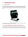
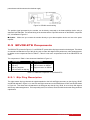
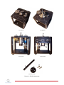
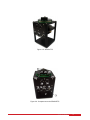
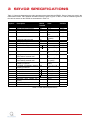
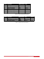
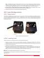
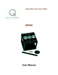
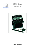
Ten modules to teach controls from the basic to advanced level
SRV02 Base Unit
Flexible Link
Inverted
Pendulum
Ball and Beam
USER MANUAL
SRV02 Rotary Servo Base Unit
Set Up and Configuration
2 DOF Robot
Flexible Joint
2 DOF Inverted
Pendulum
Gyro/Stable
Platform
Multi-DOF Torsion
Double Inverted
Pendulum
Developed by:
Jacob Apkarian, Ph.D., Quanser
Michel Lévis, M.A.Sc., Quanser
Hakan Gurocak, Ph.D., Washington State University
2 DOF Ball
Balancer
Quanser educational solutions are powered by:
With the SRV02 Base Unit, you can select from 10 add-on modules to create experiments of varying complexity across a
wide range of topics, disciplines and courses. All of the experiments/workstations are compatible with LabVIEW™ and
MATLAB®/Simulink®.
To request a demonstration or a quote, please email [email protected].
©2011 Quanser Inc. All rights reserved. LabVIEW™ is a trademark of National Instruments. MATLAB® and Simulink® are registered trademarks of The MathWorks, Inc.
[email protected]
+1-905-940-3575
Solutions for teaching and research. Made in Canada.
QUANSER.COM
CAPTIVATE. MOTIVATE. GRADUATE.
c 2011 Quanser Inc., All rights reserved.
⃝
Quanser Inc.
119 Spy Court
Markham, Ontario
L3R 5H6
Canada
[email protected]
Phone: 1-905-940-3575
Fax: 1-905-940-3576
Printed in Markham, Ontario.
For more information on the solutions Quanser Inc. offers, please visit the web site at:
http://www.quanser.com
This document and the software described in it are provided subject to a license agreement. Neither the software nor this document may be
used or copied except as specified under the terms of that license agreement. All rights are reserved and no part may be reproduced, stored in
a retrieval system or transmitted in any form or by any means, electronic, mechanical, photocopying, recording, or otherwise, without the prior
written permission of Quanser Inc.
SRV02 User Manual
2
CONTENTS
1
Presentation
1.1
Description
1.2
Rotary Modules and Experiment Overview
4
4
4
2
SRV02 Components
2.1
SRV02 Component Nomenclature
2.2
Component Description
2.3
SRV02-ETS Components
6
6
6
8
3
SRV02 Specifications
11
4
SRV02 Setup and
Configuration
4.1
Gear Configuration
4.2
Load Configurations
13
13
14
5
Wiring Procedure
5.1
Cable Nomenclature
5.2
Typical Connections
5.3
Connections for VoltPAQ-X2
15
15
16
18
6
Testing and
Troubleshooting
6.1
Motor
6.2
Potentiometer
6.3
Tachometer
6.4
Encoder
20
20
20
21
21
Technical Support
23
7
SRV02 User Manual
v 1.0
1
PRESENTATION
1.1 Description
The Quanser SRV02 rotary servo plant, pictured in Figure 1.1, consists of a DC motor that is encased in a solid
aluminum frame and equipped with a planetary gearbox. The motor has its own internal gearbox that drives external
gears. The SRV02 is equipped with three sensors: potentiometer, encoder, and tachometer. The potentiometer and
encoder sensors measure the angular position of the load gear and the tachometer can be used to measured its
velocity.
Figure 1.1: Quanser SRV02 system
There are two SRV02 options available: SRV02-ET and SRV02-ETS. The SRV02-ETS system includes a slip ring
assembly that allows the modules to be rotated the full 360 degrees.
1.2 Rotary Modules and Experiment Overview
The SRV02 rotary plant can be used stand-alone for several experiments but it also serve as a base component for
several add-on modules. Table 1.1 below lists these modules and the corresponding experiments that are supplied
with them. Thus a new plant is obtained by adding a module which presents new modeling and control challenges.
SRV02 User Manual
4
System
SRV02
SRV02
Experiment
SRV02 QUARC Integration
Modeling
SRV02
Position Control
SRV02
Speed Control
Ball and beam
Balance Control
Flexible Joint
Vibration Control
Flexible Link
Vibration Control
Single Pendulum
Self-Erecting Single
Inverted
Pendulum
Control
Double Pendulum
Double-Inverted Pendulum Balance Control
Gyroscope
Heading Control
1-DOF Torsion
Vibration Control
2 DOF Torsion
Vibration Control
2 DOF Robot
2D Task-Based Position Control
2 DOF Pendulum
2 DOF Gantry Control
2 DOF Pendulum
2 DOF Inverted Pendulum Balance Control
Ball Position Control
2D Ball Balancer
Description
Describes how to use
Model the speed of the SRV02 using a first-order transfer
function.
Regulate position of the SRV02 load gear to a desired angle using PID.
Control the angular rate of the SRV02 load gears using a
PI and a lead compensator.
Model the system and develop a cascade PD controller to
stabilize the ball to a position along the beam.
Derive the plant dynamics and design a controller that compensates for the flexibilities in the joint while regulating the
position of the arm tip to desired location.
Model the plant and identify the natural frequency of the
beam. Then, develop a system that controls the tip of beam
to a desired position.
Design a nonlinear energy-based swing-up controller and
a linear balance compensator to swing-up the pendulum
from the resting downward position to the upright vertical
position.
Model the system and then design a controller that balances the pendulum while the servo is tracking a reference
position.
Design a feedback loop that can maintains the position of
the SRV02 load gear, i.e. the heading, while the rotary
base underneath is manually perturbed.
Control the position of the output shaft to desired setpoint
by rejecting the vibrations introduced by the torsional member.
Control the position of the output shaft to desired setpoint
by rejecting the vibrations introduced by both torsional
members.
Control the position of the end-effector given a desired planar (x,y) position. This involves servo position control as
well as developing the forward and inverse kinematics of
the plant.
Control the position of the pendulum tip to a desired (x,y)
position while dampening the motions of the pendulum.
Develop a balance controller that keeps the 2 DOF pendulum in the upright vertical position.
Control the position of a ball that is free to move on a swiveling 2 DOF plate. The plate angles are controlled by attached servo units and the ball position is measured using an overhead digital camera with image processing software.
Table 1.1: SRV02-based Experiments
SRV02 User Manual
v 1.0
2
SRV02 COMPONENTS
The SRV02 components are identified in Section 2.1. Some of the those components are then described in Section
2.2.
2.1 SRV02 Component Nomenclature
The SRV02 components listed in Table 2.1 below are labeled in figures 2.1a, 2.1b, 2.1c, 2.1d, and 2.1e. Note
that Figure 2.1a shows the SRV02 in the low-gear configuration and Figure 2.1b is the SRV02 in the high-gear
configuration. These different gear setups will be explained later in Section 4.1.
ID
1
2
3
4
5
6
7
8
9
10
11
12
Component
Potentiometer
Bottom plate
Posts
Motor pinion gear: 72-teeth (low-gear)
Load gear: 72-teeth (low-gear)
Potentiometer anti-backlash gear
Anti-backlash springs
Load shaft (i.e. output shaft)
Motor
Gearbox
Potentiometer
Encoder
ID
13
14
15
16
17
18
19
20
21
22
23
Component
Tachometer
Ball-bearing block
Motor connector
Tachometer connector
Encoder connector
S1 & S2 connector (i.e. potentiometer)
Motor pinion gear: 24-teeth (high-gear)
Load gear: 120-teeth (high-gear)
Bar inertial load
Disc inertial load
Thumb screws
Table 2.1: SRV02 Components
2.2 Component Description
2.2.1 DC Motor
The SRV02 incorporates a Faulhaber Coreless DC Motor model 2338S006 and is shown in Figure 2.1c with ID #9.
This is a high efficiency, low inductance motor that can obtain a much faster response than a conventional dc motor.
The complete specification sheet of the motor is included in [2].
Caution: High-frequency signal applied to a motor will eventually damage the gearbox motor and the motor
brushes. The most likely source for high frequency noise is derivative feedback. If the derivative gain is set too high,
a noisy voltage will be fed into the motor. To protect your motor, you should always band limit your signal (especially
derivative feedback) to a value of 50 Hz.
Caution: Input ±15 V, 3 A peak, 1 A continuous.
Caution: Exposed moving parts.
2.2.2 Potentiometer
All SRV02 models are equipped with a Vishay Spectrol model 132 potentiometer, shown in in Figure 2.1c with label
#11. It is a single turn 10 kΩ sensor with no physical stops and has an electrical range of 352 deg. The total output
range of the sensor is ±5 V over the full 352 deg range. Note that a potentiometer provides an absolute position
measurement as opposed to a relative measurement from, for instance, an incremental encoder. See [6] for a full
listing of the potentiometer specifications.
SRV02 User Manual
6
Figure 2.2: SRV02 potentiometer wiring
As illustrated in Figure 2.2, the potentiometer is connected to a ±12 V DC power supply through two 7.15 kΩ bias
resistors. Under normal operations, terminal 1 should measure -5 V while terminal 3 should measure 5 V. The actual
position signal is available at terminal 2.
2.2.3 Tachometer
The SRV02-T and SRV02-ET models come equipped with a tachometer that is directly attached to the DC motor
and is depicted with ID #13 in Figure 2.1c. This prevents any latencies in the timing of the response and ensures
that the speed of the motor is accurately measured. Refer to [3] for the tachometer specification sheet.
Figure 2.3: SRV02 tachometer wiring
The motor and tachometer wiring diagram is shown in Figure 2.3. The 4-pin DIN motor connector, component #19,
connects the power amplifier to the positive and negative motor leads. This is the motor input voltage signal that
drives the motor. The 6-pin mini DIN tachometer connector, component #18 shown in Figure 2.1d, is directly wired
to the positive and negative tachometer terminals. This supplies a voltage signal that is proportional to the rotational
speed. The tachometer connector is typically connected to the S3 analog input connector on the power amplifier.
2.2.4 Encoder
The SRV02-E and SRV02-EHR options have an optical encoder installed that measures the angular position of the
load shaft. It is pictured in Figure 2.1c with the label #12. In the SRV02-E system, the encoder used is a US Digital
S1 single-ended optical shaft encoder that offers a high resolution of 4096 counts per revolution in quadrature mode
(1024 lines per revolution). The complete specification sheet of the S1 optical shaft encoder is given in [1].
The encoder in the SRV02-EHR system has a resolution of 8192 counts per revolution in quadrature mode (2042
lines per revolution). Remark that incremental encoders measure the relative angle of the shaft (as opposed to the
SRV02 User Manual
v 1.0
potentiometer which measures the absolute angle).
Figure 2.4: SRV02 encoder wiring
The position signal generated by the encoder can be directly connected to the data-acquisition device using a
standard 5-pin DIN cable. The internal wiring of the encoder and the 5-pin DIN connector on the SRV02, component
#17, is illustrated in Figure 2.4.
Caution:
amplifier.
Make sure you connect the encoder directly to your data-acquistion device and not to the power
2.3 SRV02-ETS Components
The SRV02-ETS, pictured in Figure 2.5, is an SRV02-ET system with a slip ring mounted on the load gear. This allows
an external load attached on top of the slip ring unit to rotate 360 degrees freely without any cable entanglements.
In addition to the components listed in Table 2.1, Table 2.2 lists some components found on the SRV02-ETS unit
alone.
The components in Table 2.2 are shown and identified in Figure 2.6.
ID
24
25
26
27
Component
Slip ring module chassis
Slip ring
Slip ring top plate
Left connector on slip ring
ID
28
29
30
Component
Right connector on slip ring
Left connector on SRV02
Right connector on SRV02
Table 2.2: Additional components on the SRV02-ETS
2.3.1 Slip Ring Description
The eight-contact slip ring channels the signals attached to the Left and Right connectors on the slip ring, ID #27
and ID #28 depicted in Figure 2.6, to the Left and Right connectors on the SRV02 base, ID #27 and ID #28 shown
in Figure 2.6. This allows the load attached to the load gear atop the slip ring, ID #8, to move freely 360 degrees
without any cable entanglements. This is especially useful, for instance, when used with the inverted rotary pendulum
experiments.
SRV02 User Manual
8
(a) Low-gear
(b) High-gear
(c) Front view
(d) Connectors
(e) Inertial Loads
Figure 2.1: SRV02 components
SRV02 User Manual
v 1.0
Figure 2.5: SRV02-ETS
Figure 2.6: Components on the SRV02-ETS
SRV02 User Manual
10
3
SRV02 SPECIFICATIONS
Table 3.1 lists and characterizes the main parameters associated with the SRV02. Some of these are used in the
mathematical model. More detailed information about the gears is given in Table 3.2 and the calibration gains for
the various sensors on the SRV02 are summarized in Table 3.3.
Symbol
Description
Vnom
Rm
Lm
kt
Motor nominal input voltage
Motor armature resistance
Motor armature inductance
Motor current-torque constant
Rm
Lm
kt
km
Motor back-emf constant
km
Kg
ηm
ηg
Jm,rotor
High-gear total gear ratio
Low-gear total gear ratio
Motor efficiency
Geabox efficiency
Rotor moment of inertia
Kg
Kg
eta m
eta g
Jm rotor
Jtach
Tachometer moment of inertia
Jtach
Jeq
High-gear equivalent moment of
inerta without external load
Low-gear equivalent moment of
inerta without external load
High-gear Equivalent viscous
damping coefficient
Low-Gear Equivalent viscous
damping coefficient
Mass of bar load
Length of bar load
Mass of disc load
Radius of disc load
Maximum load mass
Maximum input voltage frequency
Maximum input current
Maximum motor speed
Jeq
Beq
mb
Lb
md
rd
mmax
fmax
Imax
ωmax
Matlab
Variable
Jeq
Beq
Beq
mb
Lb
md
rd
Value
6.0 V
2.6 Ω
0.18 mH
7.68 × 10⁻³ N
m/A
7.68 × 10⁻³
V/(rad/s)
70
14
0.69
0.90
3.90 × 10⁻⁷ kg ·
m2
7.06 × 10⁻⁸ kg ·
m2
9.76 × 10⁻⁵ kg ·
m2
2.08 × 10⁻⁵ N ·
m / (rad/s)
0.015 N · m /
(rad/s)
1.50 × 10⁻⁴ kg ·
m2
0.038 kg
0.1525 m
0.04 kg
0.05 m
5 kg
50 Hz
Variation
± 12%
± 12%
± 12%
± 5%
± 10%
± 10%
± 10%
1A
628.3 rad/s
Table 3.1: Main SRV02 Specifications
SRV02 User Manual
v 1.0
Symbol
Kgi
Kge,low
Kge,high
m24
m72
m120
r24
r72
r120
Description
Internal gearbox ratio
Internal gearbox ratio (low-gear)
Internal gearbox ratio (high-gear)
Mass of 24-tooth gear
Mass of 72-tooth gear
Mass of 120-tooth gear
Radius of 24-tooth gear
Radius of 72-tooth gear
Radius of 120-tooth gear
Matlab Variable
Kgi
Kge
Kge
m24
m72
m120
r24
r72
r120
Value
14
1
5
0.005 kg
0.030 kg
0.083 kg
6.35 × 10⁻³ m
0.019 m
0.032 m
Table 3.2: SRV02 Gearhead Specifications
Symbol
Kpot
Kenc
Kenc
Ktach
Description
Potentiometer sensitivity
SRV02-E encoder sensitivity
SRV02-EHR encoder sensitivity
Tachometer sensitivity
Matlab Variable
K POT
K ENC
K ENC
K TACH
Value
35.2 deg/V
4096 counts/rev
8192 counts/rev
1.50 V/kRPM
Variation
±2%
±2%
Table 3.3: SRV02 Sensor Specifications
SRV02 User Manual
12
4
SRV02 SETUP AND
CONFIGURATION
As discussed in Section 4.1, the SRV02 can be setup with two different gear configurations depending on the experiment being performed. Also, Section 4.2 shows how the SRV02 can be fitted with different loads.
4.1 Gear Configuration
4.1.1 Description
The SRV02 can be setup in the low-gear configuration or the high-gear configuration, as pictured in Figure 4.1a
and Figure 4.1b, respectively. The high-gear setup is required to be used with additional modules such as the
ball-and-beam device, the flexible link module, and the gyroscope.
(a) Low-gear
(b) High-gear
Figure 4.1: SRV02 Gear Configurations
4.1.2 Changing Gear Configuration
Follow this procedure to change between high-gear and low-gear ratio:
1. Using the supplied Allen keys, loosen the set screws on the three gear shafts.
2. Remove the gears from the shafts.
3. Slide the new gears into place as described below:
• Low-gear configuration shown in Figure 4.1a: place the 72-tooth gear, ID #5 in Figure 2.1a, onto the load
shaft, ID #8 in Figure 2.1a, and the 72-tooth pinion gear, ID #4 in Figure 2.1a, on the motor shaft.
• High-gear configuration depicted in Figure 4.1b: slide the 120-tooth gear, ID #20 in Figure 2.1b, followed
by the 72-tooth gear, ID #8 in Figure 2.1b, on the load shaft and place the 20-tooth pinion gear, ID #19 in
Figure 2.1b, on the motor shaft.
SRV02 User Manual
v 1.0
Note: The potentiometer gear, component #6 in Figure 2.1b, is an anti-backlash gear and special precaution
need to be taken when installing it. In order to insert it properly, rotate its two faces against each other such
that the springs are partially pre-loaded. Do not fully extend the springs when you pre-load the gears.
4. Ensure the teeth of all the three gears are meshed together. Remark that in the high-gear setup, the top
72-tooth load gear is meshed with the potentiometer gear, ID #6 in Figure 2.1b.
5. Tighten the set-screws on each shaft with the supplied Allen keys.
4.2 Load Configurations
4.2.1 Description
The SRV02 is supplied with two external loads: a bar and a disk. These can be attached to the SRV02 load gear
to vary the moment of inertia seen at the output. The SRV02 with the end of the bar load connected is pictured in
Figure 4.2a. Either the end of the bar or the center of the bar can be used. In Figure 4.2b the SRV02 with the disk
load attached is shown.
(a) Bar load
(b) Disc load
Figure 4.2: SRV02 Load Configurations
4.2.2 Installing Load
Follow this procedure to connect either the bar or disc load to the load gear:
1. Slide the center hole of the load on the output shaft of the SRV02, component #8 in Figure 2.1b. For the bar
load (ID #21 in Figure 2.1e), use either the center hole in the middle of the bar or the center hole at the an end
of the bar onto the output shaft.
2. Align the two holes adjacent to the center hole with the screw holes of the load gear.
3. Using the two 8-32 thumb screws provided, ID #23 in Figure 2.1e, fasten the inertial load to the output gear.
The SRV02 with the bar load and the disk load attached is shown in Figure 4.2a and Figure 4.2b, respectively.
Make sure all the screws are properly tightened before operating the servo unit.
Caution: Do not apply a load that weighs over 5 kg at any time.
For instructions on how to install one the SRV02 modules (e.g. rotary flexible joint) see the user manual corresponding to that module.
SRV02 User Manual
14
5
WIRING PROCEDURE
The following is a listing of the hardware components used in this experiment:
1. Power Amplifier: Quanser VoltPAQ-X1, or equivalent.
2. Data Acquisition Board: Quanser QPID, QPIDe, Q8-USB, Q2-USB, or equivalent.
3. Rotary Servo Plant: Quanser SRV02-ET, SRV02-ETS, or equivalent.
See the corresponding documentation for more information on these components. The cables supplied with the
SRV02 are described in Section Section 5.1 and the procedure to connect the above components is given in Section
5.2.
Caution: When using the Quanser VoltPAQ-X1 power amplifier, make sure you set the Gain to 1!
5.1 Cable Nomenclature
The cables used to connect the Quanser SRV02 system with a power amplifier and data-acquisition device is shown
in Table 5.1. Depending on your configuration, not all these cables are necessary.
SRV02 User Manual
v 1.0
Cable
Type
2xRCA to 2xRCA
Description
This cable connects an analog output of the
data acquisition terminal board to the power
module for proper power amplification.
4-pin-DIN to 6-pinDIN
This cable connects the output of the power
module, after amplification, to the desired DC
motor on the servo.
5-pin-stereo-DIN to
5-pin-stereo-DIN
This cable carries the encoder signals between an encoder connector and the data
acquisition board (to the encoder counter).
Namely, these signals are: +5 VDC power
supply, ground, channel A, and channel B
6-pin-mini-DIN
6-pin-mini-DIN
to
5-pin-DIN
4xRCA
to
This cable carries analog signals (e.g., from
joystick, plant sensor) to the amplifier, where
the signals can be either monitored and/or
used by a controller. The cable also carries
a ± 12 VDC line from the amplifier in order
to power a sensor and/or signal conditioning
circuitry.
This cable carries the analog signals, unchanged, from the amplifier to the Digital-ToAnalog input channels on the data acquisition
terminal board.
(a) RCA Cable
(b) Motor Cable
(c) Encoder Cable
(d) Analog Cable
(e) 5-pin-DIN to 4xRCA
Table 5.1: Cables used to connect SRV02 to amplifier and DAQ device
5.2 Typical Connections
This section describes the typical connections used to connect the SRV02 plant to a data-acquisition board and
a power amplifier. The connections are described in detail in the procedure below, summarized in Table 5.2, and
pictured in Figure 5.1.
Note: The wiring diagram shown in Figure 5.1 is using a two-channel data-acquisition board, which resembles a
Quanser Q2-USB. The same connections can be applied for any data-acquisition system - as long as it has least
two analog input, two analog output, and two encoder channels.
Follow these steps to connect the SRV02 system:
SRV02 User Manual
16
1. Make sure that your data-acquisition device is installed and is operational. For example, if using the Quanser
Q2-USB see Reference [5].
2. Make sure everything is powered off before making any of these connections. This includes turning off your
PC and the amplifier.
3. Connect one end of the 2xRCA to 2xRCA cable from the Analog Output Channel #0 on the terminal board
to the Amplifier Command connector on the amplifier, i.e. use both white or both red RCA connectors. See
cable #1 shown in Figure 5.1. This carries the attenuated motor voltage control signal, Vm /Ka , where Ka is
the amplifier gain.
4. Connect the 4-pin-stereo-DIN to 6-pin-stereo-DIN that is labeled from To Load on the amplifier to the Motor
connector on the SRV02. See connection #2 shown in Figure 5.1. The cable transmits the amplified voltage
that is applied to the SRV02 motor and is denoted Vm .
5. Connect the 5-pin-stereo-DIN to 5-pin-stereo-DIN cable from the Encoder connector on the SRV02 panel to
Encoder Input # 0 on the terminal board, as depicted by connection #3 in Figure 5.1. This carries the load
shaft angle measurement and is denoted by the variable θl .
Caution: Any encoder should be directly connected to the data-acquisition terminal board (or equivalent)
using a standard 5-pin DIN cable. DO NOT connect the encoder cable to the amplifier!
6. Connect the To ADC socket on the amplifier to Analog Inputs #0-1 on the terminal board using the 5-pin-DIN
to 4xRCA cable, as illustrated in Figure 5.1. The RCA side of the cable is labeled with the channels: yellow is
S1, white is S2, red is S3, and black is S4. The yellow S1 connector goes to Analog Input Channel #0 and the
white S2 connector goes to Analog Input Channel #1.
7. Connect the TACH connector on the SRV02 to the S1 & S2 socket on the SRV02 using the 6-pin-mini-DIN
to 6-pin-mini-DIN cable. This connection is labeled #5 in Figure 5.1. It combines the potentiometer (S1)
measurement with the tachometer (S2) measurement.
8. Connect the S1 & S2 connector on the SRV02 to the S1 & S2 socket on the amplifier using the 6-pin-mini-DIN
to 6-pin-mini-DIN cable. See connection #6 in Figure 5.1. This carries the potentiometer (S1) and tachometer
(S2) signals. The measured load shaft rate from the tachometer is denoted by the variable ωl and the load
shaft angle is represented by variable θl .
Cable
#
1
2
3
4
From
To
Signal
Terminal Board: Analog
Output #0
Amplifier: To Load connector
Terminal Board: Encoder
Input #0
Amplifier: To ADC connector
Amplifier Amplifier Command
connector
SRV02 Motor connector
Control signal to the amplifier.
SRV02 Encoder connector
Encoder load shaft angle measurement.
Connects analog sensor signals S1
and S2 to Analog Input Channels #0
and #1, respectively.
Terminal Board:
• S1 to Analog Input #0
Power leads to the SRV02 dc motor.
• S2 to Analog Input #1
5
6
SRV02 S1 & S2 connector
Amplifier S1 & S2 connector
SRV02 TACH connector
SRV02 S1 & S2 connector
Combine potentiometer (S1) and
tachometer (S2) signals.
Potentiometer load shaft angle (S1)
measurement and tachometer (S2)
load shaft rate measurement.
Table 5.2: SRV02 Wiring
SRV02 User Manual
v 1.0
Figure 5.1: Connecting the SRV02 to a Single-Channel Amplifier and Two-Channel DAQ
5.3 Connections for VoltPAQ-X2
Some amplifiers, such as the Quanser VoltPAQ-X2, need to be enabled and have an emergency switch connected.
The amplifier may not have an analog sensor interface built-in either - requiring an external device. This section
describes the wiring required for that configuration. The connections are summarized in Table 5.3 and depicted in
Figure 5.2.
Note: The wiring diagram shown in Figure 5.1 is using a two-channel data-acquisition board, which resembles a
Quanser Q2-USB. The same connections can be applied for any data-acquisition system - as long as it has least
two analog input, two analog output, and two encoder channels.
The power amplifier used resembles a VoltPAQ-X2 system, which is a two-channel amplifier that requires digital
enabling and an emergency stop switch to be connected. Remark that the analog sensor are interfaced through an
Analog Signal Conditioner box to split the potentiometer (S1) and tachometer (S2) channels.
SRV02 User Manual
18
Cable
#
1
2
3
4
5
6
7
8
9
From
To
Signal
Terminal Board: Analog
Output #0
Amplifier: To Load connector
Terminal Board: Encoder
Input #0
Analog Signal Conditioner
S1 Output
Analog Signal Conditioner
S2 Output
SRV02 S1 & S2 connector
Analog Signal Conditioner
Input 1 connector
Amplifier Amplifier Command
connector
SRV02 Motor connector
Control signal to the amplifier.
SRV02 Encoder connector
Amplifier 16-pin connector (Enable/Fault)
Emergency Stop Switch
Terminal Board: DIO 0 connector
Amplifier E-Stop connector
Encoder load shaft angle measurement.
Connects potentiometer to Analog Input Channel #0
Connects tachometer to Analog Input
Channel #1
Combines potentiometer (S1) and
tachometer (S2) signals.
Potentiometer load shaft angle (S1)
measurement and tachometer (S2)
load shaft rate measurement.
Enable signal for the amplifier channels
Terminal Board: Analog Input
#0.
Terminal Board: Analog Input
#1.
SRV02 TACH connector
SRV02 S1 & S2 connector
Power leads to the SRV02 dc motor.
Emergency stop signal
Table 5.3: SRV02 connections for amplifier requiring enabling and E-Stop
Figure 5.2: Connecting the SRV02 to a Two-Channel Amplifier and Two-Channel DAQ
SRV02 User Manual
v 1.0
6
TESTING AND
TROUBLESHOOTING
This section describes some functional tests to determine if your SRV02 is operating normally. It is assumed that
the SRV02 is connected as described in the Section 5, above. To carry out these tests, it is preferable if the user can
use a software such as QUARCr or LabVIEWr to read sensor measurements and feed voltages to the motor. See
Reference [4] to learn how to interface the SRV02 with QUARC. Alternatively, these tests can be performed with a
signal generator and an oscilloscope.
6.1 Motor
6.1.1 Testing
Ensure the SRV02 motor is operating correctly by going through this procedure:
1. Apply a voltage to analog output channel #0 of the terminal board using, for example, the QUARC software.
2. The motor gear, component #4 shown in Figure 2.1b, should rotate counter-clockwise when a positive voltage
is applied and clockwise when a negative voltage is applied. Remark that the motor shaft and the load shaft
turn in opposite directions.
6.1.2 Troubleshooting
If the motor is not responding to a voltage signal, go through these steps:
• Verify that the power amplifier is functional. For example when using the Quanser VoltPAQ device, is the green
LED lit?
• Check that the data-acquisition board is functional, e.g. ensure it is properly connected, that the fuse is not
burnt.
• Make sure the voltage is actually reaching the motor terminals (use a voltmeter or oscilloscope).
• If the motor terminals are receiving the signal and the motor is still not turning, your motor might be damaged
and will need to be repaired. Please see Section 7 for information on contacting Quanser for technical support.
6.2 Potentiometer
6.2.1 Testing
Test the SRV02 potentiometer with the following procedure:
1. Using a program such as QUARC, measure the analog input channel #0.
2. The potentiometer should output a positive voltage when the potentiometer gear, component #6 in Figure 2.1b,
is rotated counter-clockwise. The measurement should increase positively towards 5 V until the discontinuity
is reached, at which point the signal abruptly changes to -5 V and begins to increase again.
SRV02 User Manual
20
6.2.2 Troubleshooting
Follow the steps below if the potentiometer is not measuring correctly::
• Verify that the power amplifier is functional. For example when using the Quanser VoltPAQ device, is the
green LED lit? Recall the analog sensor signal go through the amplifier before going to the data-acquisition
device (except when using the Q3 ControlPAQ). Therefore the amplifier needs to be turned on to read the
potentiometer.
• Check that the data-acquisition board is functional, e.g. ensure it is properly connected, that the fuse is not
burnt.
• Measure the voltage across the potentiometer. Ensure the potentiometer is powered with a ±12 V at the 6-pinmini DIN connector and ±5 V at the potentiometer terminals, as described in Section 2.2.2. If the voltage from
the wiper does not change when you rotate the potentiometer shaft, your potentiometer needs to be replaced.
Please see Section 7 for information on contacting Quanser for technical support.
6.3 Tachometer
6.3.1 Testing
Test the tachometer on the SRV02 by performing the following:
1. Apply a 2.0 V signal to Analog Output Channel #0 in order to drive the motor.
2. Measure Analog Input Channel #2 to read the tachometer. When applying 2.0 V to the motor, the tachometer
should be measuring a value of approximately 3.0 V.
6.3.2 Troubleshooting
If no signals are received from the tachometer, go through this method:
• Verify that the power amplifier is functional. For example when using the Quanser VoltPAQ device, is the green
LED lit? Recall the analog sensor signal go through the amplifier before going to the data-acquisition device
(except when using the Q3 ControlPAQ). It needs to be turned on to read from the tachometer.
• Check that the data-acquisition board is functional, e.g. ensure it is properly connected, that the fuse is not
burnt.
• Measure the voltage across the tachometer. When moving the load gear back and forth, is the voltage being
measured changing? If not, then the tachometer needs to be replaced. Please see Section 7 for information
on contacting Quanser for technical support.
6.4 Encoder
6.4.1 Testing
Follow this procedure to test the SRV02 encoder:
1. Measure Encoder Input Channel #0 using, for instance, the QUARC software.
SRV02 User Manual
v 1.0
2. Rotate the SRV02 load gear, component #5 in Figure 2.1b, one rotation and the encoder should measure 4096
counts (or 8192 when using the SRV02-EHR option) in quadrature mode.
Note: Some data acquisition systems do not measure in quadrature and, in this case, one-quarter of the
expected counts are received, i.e. 1024 counts in the SRV02-E or 2048 in the SRV02-EHR. In addition, some
data acquisition systems measure in quadrature but increment the count by 0.25 (as opposed to having an
integer number of counts). Make sure the details of the data-acquisition system being used is known. The
counters on the Quanser DAQ boards measure in quadrature and therefore a total of four times the number
of encoder lines per rotation, e.g. a 1024-line encoder results in 4096 integer counts for every full rotation.
6.4.2 Troubleshooting
If the encoder is not measuring properly, go through this procedure:
• Check that the data-acquisition board is functional, e.g. ensure it is properly connected, that the fuse is not
burnt.
• Check that both the A and B channels from the encoder are properly generated and fed to the data-acquisition
device. Using an oscilloscope, there should be two square waves, signals A and B, with a phase shift of 90
degrees. If this is not observed then the encoder may be damaged and need to be replaced. Please see
Section 7 for information on contacting Quanser for technical support.
SRV02 User Manual
22
7
TECHNICAL SUPPORT
To obtain support from Quanser, go to http://www.quanser.com/ and click on the Tech Support link. Fill in the form
with all the requested software and hardware information as well as a description of the problem encountered. Also,
make sure your e-mail address and telephone number are included. Submit the form and a technical support person
will contact you.
SRV02 User Manual
v 1.0
REFERENCES
[1] US Digital. E2 optical kit encoder. 2007.
[2] Faulhaber. Dc-micromotors series 2338. 2002.
[3] Faulhaber. Dc-motor-tacho combinations. 2002.
[4] Quanser Inc. Srv02 quarc integration. 2008.
[5] Quanser Inc. Q2-usb data-acquisition system user's guide. 2010.
[6] Vishay Spectrol. Model 132, 138, 139. 2001.
SRV02 User Manual
24
Ten modules to teach controls from the basic to advanced level
SRV02 Base Unit
Flexible Link
Inverted
Pendulum
Ball and Beam
USER MANUAL
SRV02 Rotary Servo Base Unit
Set Up and Configuration
2 DOF Robot
Flexible Joint
2 DOF Inverted
Pendulum
Gyro/Stable
Platform
Multi-DOF Torsion
Double Inverted
Pendulum
Developed by:
Jacob Apkarian, Ph.D., Quanser
Michel Lévis, M.A.Sc., Quanser
Hakan Gurocak, Ph.D., Washington State University
2 DOF Ball
Balancer
Quanser educational solutions are powered by:
With the SRV02 Base Unit, you can select from 10 add-on modules to create experiments of varying complexity across a
wide range of topics, disciplines and courses. All of the experiments/workstations are compatible with LabVIEW™ and
MATLAB®/Simulink®.
To request a demonstration or a quote, please email [email protected].
©2011 Quanser Inc. All rights reserved. LabVIEW™ is a trademark of National Instruments. MATLAB® and Simulink® are registered trademarks of The MathWorks, Inc.
[email protected]
+1-905-940-3575
Solutions for teaching and research. Made in Canada.
QUANSER.COM
CAPTIVATE. MOTIVATE. GRADUATE.