1
POC2502 Series
User Manual
P/N 1073045 • REV A • ISS 27AUG15
1
Copyright
Trademarks and
patents
Manufacturer
© 2015 United Technologies Corporation
Interlogix is part of UTC Building & Industrial Systems,Inc. a unit of United
Technologies Corporation. All rights reserved.
The POC2502 Series name and logo are trademarks of United Technologies.
Other trade names used in this document may be trademarks or registered
trademarks of the manufacturers or vendors of the respective products.
Interlogix
3211 Progress Drive,
Lincolnton, NC 28092 USA
Authorized EU manufacturing representative:
UTC Climate Controls & Security B.V.,
Kelvinstraat 7, 6003 DH Weert, Netherlands
Intended use
Use this product only for the purpose it was designed for; refer to the data sheet
and user documentation for details. For the latest product information, contact
your local supplier or visit us online at www.interlogix.com.
Certification
N4131
FCC compliance
This equipment has been tested and found to comply with the limits for a Class
A digital device, pursuant to part 15 of the FCC Rules. These limits are
designed to provide reasonable protection against harmful interference when
the equipment is operated in a commercial environment. This equipment
generates, uses, and can radiate radio frequency energy and, if not installed
and used in accordance with the instruction manual, may cause harmful
interference to radio communications.
You are cautioned that any changes or modifications not expressly approved by
the party responsible for compliance could void the user's authority to operate
the equipment.
ACMA compliance
Notice! This is a Class A product. In a domestic environment this product may
cause radio interference in which case the user may be required to take
adequate measures.
Canada
This Class A digital apparatus complies with Canadian ICES-003.
Cet appareil numérique de la classe A est conforme á la norme NMB-003du
Canada.
European Union
directives
2004/108/EC (EMC Directive): Hereby, UTC Building & Industrial Systems, Inc.
declares that this device is in compliance with the essential requirements and
other relevant provisions of Directive 2004/108/EC.
Contact Information
For contact information, see www.interlogix.com or
www.utcfssecurityproducts.eu.
2
TABLE OF CONTENTS
1. INTRODUCTION .................................................................................................................... 10
1.1 Packet Contents ....................................................................................................................................... 10
1.2 Product Description ................................................................................................................................. 11
1.3 How to Use This Manual .......................................................................................................................... 16
1.4 Product Features ...................................................................................................................................... 16
1.5 Product Specifications ............................................................................................................................ 19
2. INSTALLATION ...................................................................................................................... 25
2.1 Hardware Description .............................................................................................................................. 25
2.1.1 Switch Front Panel ............................................................................................................................................... 25
2.1.2 LED Indications .................................................................................................................................................... 26
2.1.3 Switch Rear Panel ............................................................................................................................................... 28
2.2 Installing the Switch................................................................................................................................. 29
2.2.1 Desktop Installation .............................................................................................................................................. 29
2.2.2 Rack Mounting ..................................................................................................................................................... 30
2.2.3 Installing the SFP transceiver .............................................................................................................................. 31
2.2.4 Installing the Long Reach PoE Communication ................................................................................................... 33
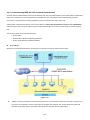
3. SWITCH MANAGEMENT ...................................................................................................... 38
3.1 Requirements ........................................................................................................................................... 38
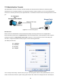
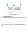
3.2 Management Access Overview ............................................................................................................... 39
3.3 Administration Console ........................................................................................................................... 40
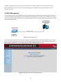
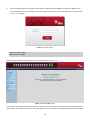
3.4 Web Management ..................................................................................................................................... 41
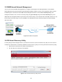
3.5 SNMP-based Network Management ....................................................................................................... 42
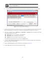
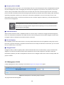
3.6 IFS Smart Discovery Utility ..................................................................................................................... 42
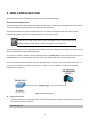
4. WEB CONFIGURATION ........................................................................................................ 44
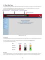
4.1 Main Web Page ......................................................................................................................................... 47
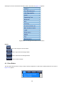
4.1.1 Save Button ......................................................................................................................................................... 48
4.1.2 Configuration Manager ........................................................................................................................................ 49
4.1.2.1 Saving Configuration ................................................................................................................................. 50
3
4.2 System ...................................................................................................................................................... 51
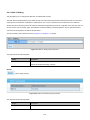
4.2.1 System Information .............................................................................................................................................. 51
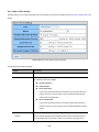
4.2.2 IP Configurations.................................................................................................................................................. 52
4.2.3 IPv6 Configuration ............................................................................................................................................... 54
4.2.4 User Configuration ............................................................................................................................................... 56
4.2.5 Time Settings ....................................................................................................................................................... 57
4.2.5.1 System Time .............................................................................................................................................. 57
4.2.5.2 SNTP Server Settings ................................................................................................................................ 60
4.2.6 Log Management ................................................................................................................................................. 61
4.2.6.1 Local Log ................................................................................................................................................... 61
4.2.6.2 Local Log ................................................................................................................................................... 62
4.2.6.3 Remote Syslog .......................................................................................................................................... 64
4.2.6.4 Log Message ............................................................................................................................................. 65
4.2.7 SNMP Management ............................................................................................................................................. 68
4.2.7.1 SNMP Overview......................................................................................................................................... 68
4.2.7.2 SNMP System Information......................................................................................................................... 69
4.2.7.3 SNMP View ................................................................................................................................................ 70
4.2.7.4 SNMP Access Group ................................................................................................................................. 72
4.2.7.5 SNMP Community ..................................................................................................................................... 73
4.2.7.6 SNMP User ................................................................................................................................................ 75
4.2.7.7 SNMPv1, 2 Notification Recipients ............................................................................................................ 76
4.2.7.9 SNMPv3 Notification Recipients ................................................................................................................ 77
4.2.7.10 SNMP Engine ID ...................................................................................................................................... 79
4.2.7.11 SNMP Remote Engine ID ........................................................................................................................ 80
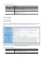
4.3 Port Management ..................................................................................................................................... 82
4.3.1 Port Configuration ................................................................................................................................................ 82
4.3.2 POC Port Configuration ....................................................................................................................................... 84
4.3.3 Port Counters ....................................................................................................................................................... 85
4.3.4 Bandwidth Utilization ............................................................................................................................................ 90
4.3.5 Port Mirroring ....................................................................................................................................................... 91
4.3.6 Jumbo Frame ....................................................................................................................................................... 93
4.3.7 Port Error Disabled Configuration ........................................................................................................................ 94
4.3.8 Port Error Disabled............................................................................................................................................... 96
4.3.9 Protected Ports .................................................................................................................................................... 96
4.3.10 EEE .................................................................................................................................................................... 99
4.4 Link Aggregation .................................................................................................................................... 101
4.4.1 LAG Setting ........................................................................................................................................................ 103
4.4.2 LAG Managment ................................................................................................................................................ 104
4.4.3 LAG Port Setting ................................................................................................................................................ 105
4.4.4 LACP Setting...................................................................................................................................................... 107
4
4.4.5 LACP Port Setting .............................................................................................................................................. 108
4.4.6 LAG Status ......................................................................................................................................................... 109
4.5 VLAN ....................................................................................................................................................... 112
4.5.1 VLAN Overview ...................................................................................................................................................112
4.5.2 IEEE 802.1Q VLAN .............................................................................................................................................113
4.5.3 Management VLAN .............................................................................................................................................116
4.5.4 Create VLAN .......................................................................................................................................................117
4.5.5 Interface Settings ................................................................................................................................................118
4.5.6 Port to VLAN ...................................................................................................................................................... 123
4.5.7 Port VLAN Membership ..................................................................................................................................... 124
4.5.8 Protocol VLAN Group Setting ............................................................................................................................ 125
4.5.9 Protocol VLAN Port Setting ................................................................................................................................ 126
4.5.10 GVRP Setting ................................................................................................................................................... 128
4.5.11 GVRP Port Setting ........................................................................................................................................... 130
4.5.12 GVRP VLAN..................................................................................................................................................... 132
4.5.13 GVRP Statistics ................................................................................................................................................ 132
4.5.14 VLAN setting example: .................................................................................................................................... 134
4.5.14.1 Two Separate 802.1Q VLANs ................................................................................................................ 134
4.5.14.2 VLAN Trunking between Two 802.1Q Aware Switches ......................................................................... 137
4.6 Spanning Tree Protocol ......................................................................................................................... 140
4.6.1 Theory ................................................................................................................................................................ 140
4.6.2 STP Global Settings ........................................................................................................................................... 146
4.6.3 STP Port Setting ................................................................................................................................................ 148
4.6.4 CIST Instance Setting ........................................................................................................................................ 151
4.6.5 CIST Port Setting ............................................................................................................................................... 153
4.6.6 MST Instance Configuration............................................................................................................................... 154
4.6.7 MST Port Setting ................................................................................................................................................ 157
4.6.8 STP Statistics ..................................................................................................................................................... 159
4.7 Multicast.................................................................................................................................................. 160
4.7.1 Properties ........................................................................................................................................................... 160
4.7.2 IGMP Snooping .................................................................................................................................................. 162
4.7.2.1 IGMP Setting............................................................................................................................................ 166
4.7.2.2 IGMP Querier Setting............................................................................................................................... 168
4.7.2.3 IGMP Static Group ................................................................................................................................... 169
4.7.2.4 IGMP Group Table ................................................................................................................................... 170
4.7.2.5 IGMP Router Setting ................................................................................................................................ 171
4.7.2.6 IGMP Router Table .................................................................................................................................. 172
4.7.2.7 IGMP Forward All ..................................................................................................................................... 173
4.7.3 IGMP Snooping Statics ...................................................................................................................................... 174
4.7.4 MLD Snooping ................................................................................................................................................... 176
5
4.7.4.1 MLD Setting ............................................................................................................................................. 176
4.7.4.2 MLD Static Group..................................................................................................................................... 178
4.7.4.3 MLD Group Table ..................................................................................................................................... 179
4.7.4.4 MLD Router Setting ................................................................................................................................. 179
4.7.4.5 MLD Router Table .................................................................................................................................... 181
4.7.4.6 MLD Forward All ...................................................................................................................................... 182
4.7.5 MLD Snooping Statics ........................................................................................................................................ 183
4.7.6 Multicast Throttling Setting ................................................................................................................................. 185
4.7.7 Multicast Filter .................................................................................................................................................... 186
4.7.7.1 Multicast Profile Setting ........................................................................................................................... 187
4.7.7.2 IGMP Filter Setting................................................................................................................................... 188
4.7.7.3 MLD Filter Setting .................................................................................................................................... 189
4.8 Quality of Service ................................................................................................................................... 191
4.8.1 Understand QoS ................................................................................................................................................ 191
4.8.2 General .............................................................................................................................................................. 192
4.8.2.1 QoS Properties ........................................................................................................................................ 192
4.8.2.2 QoS Port Settings .................................................................................................................................... 193
4.8.2.3 Queue Settings ........................................................................................................................................ 194
4.8.2.4 CoS Mapping ........................................................................................................................................... 195
4.8.2.5 DSCP Mapping ........................................................................................................................................ 197
4.8.2.6 IP Precedence Mapping........................................................................................................................... 199
4.8.3 QoS Basic Mode ................................................................................................................................................ 200
4.8.3.1 Global Settings ........................................................................................................................................ 200
4.8.3.2 Port Settings ............................................................................................................................................ 201
4.8.4 Rate Limit ........................................................................................................................................................... 202
4.8.4.1 Ingress Bandwidth Control ....................................................................................................................... 202
4.8.4.2 Egress Bandwidth Control ....................................................................................................................... 204
4.8.4.3 Egress Queue .......................................................................................................................................... 205
4.8.5 Voice VLAN ........................................................................................................................................................ 207
4.5.8.1 Introduction to Voice VLAN ...................................................................................................................... 207
4.8.5.2 Properties................................................................................................................................................. 207
4.8.5.3 Telephony OUI MAC Setting .................................................................................................................... 209
4.8.5.4 Telephony OUI Port Setting ......................................................................................................................211
4.9 Security ................................................................................................................................................... 213
4.9.1 802.1X ................................................................................................................................................................ 213
4.9.1.1 Understanding IEEE 802.1X Port-based Authentication .......................................................................... 214
4.9.1.2 802.1X Setting ......................................................................................................................................... 217
4.9.1.3 802.1X Port Setting .................................................................................................................................. 218
4.9.1.4 Guest VLAN Setting ................................................................................................................................. 220
4.9.1.5 Authenticated Host ................................................................................................................................... 223
6
4.9.2 RADIUS Server .................................................................................................................................................. 223
4.9.3 TACACS+ Server ............................................................................................................................................... 226
4.9.4 AAA .................................................................................................................................................................... 229
4.9.4.1 Login List ................................................................................................................................................. 230
4.9.4.2 Enable List ............................................................................................................................................... 231
4.9.5 Access ................................................................................................................................................................ 232
4.9.5.1 Telnet ....................................................................................................................................................... 232
4.9.5.2 SSH.......................................................................................................................................................... 233
4.9.5.3 HTTP........................................................................................................................................................ 235
4.9.5.4 HTTPs ...................................................................................................................................................... 237
4.9.6 Management Access Method ............................................................................................................................. 238
4.9.6.1 Profile Rules............................................................................................................................................. 238
4.9.6.2 Access Rules ........................................................................................................................................... 239
4.9.7 DHCP Snooping ................................................................................................................................................. 241
4.9.7.1 DHCP Snooping Overview....................................................................................................................... 241
4.9.7.2 Global Setting .......................................................................................................................................... 242
4.9.7.3 VLAN Setting ........................................................................................................................................... 243
4.9.7.4 Port Setting .............................................................................................................................................. 245
4.9.7.5 Statistics ................................................................................................................................................... 246
4.9.7.6 Database Agent ....................................................................................................................................... 247
4.9.7.7 Rate Limit ................................................................................................................................................. 249
4.9.7.8 Option 82 Global Setting .......................................................................................................................... 251
4.9.7.9 Option 82 Port Setting ............................................................................................................................. 252
4.9.7.10 Option 82 Circuit-ID Setting ................................................................................................................... 254
4.9.8 Dynamic ARP Inspection.................................................................................................................................... 255
4.9.8.1 Global Setting .......................................................................................................................................... 255
4.9.8.2 VLAN Setting ........................................................................................................................................... 256
4.9.8.3 Port Setting .............................................................................................................................................. 257
4.9.8.4 Statistics ................................................................................................................................................... 259
4.9.8.5 Rate Limit ................................................................................................................................................. 260
4.9.9 IP Source Guard ................................................................................................................................................ 261
4.9.9.1 Port Settings ............................................................................................................................................ 262
4.9.9.2 Binding Table ........................................................................................................................................... 263
4.9.10 Port Security..................................................................................................................................................... 265
4.9.11 DoS .................................................................................................................................................................. 267
4.9.11.1 Global DoS Setting................................................................................................................................. 267
4.9.11.2 DoS Port Setting .................................................................................................................................... 270
4.9.12 Storm Control ................................................................................................................................................... 272
4.9.12.1 Global Setting ........................................................................................................................................ 272
4.9.12.2 Port Setting ............................................................................................................................................ 273
4.10 ACL ........................................................................................................................................................ 275
7
4.10.1 MAC-based ACL .............................................................................................................................................. 275
4.10.2 MAC-based ACE .............................................................................................................................................. 276
4.10.3 IPv4-based ACL ............................................................................................................................................... 279
4.10.4 IPv4-based ACE ............................................................................................................................................... 279
4.10.5 IPv6-based ACL ............................................................................................................................................... 284
4.10.6 IPv6-based ACE ............................................................................................................................................... 285
4.10.7 ACL Binding ..................................................................................................................................................... 290
4.11 MAC Address Table .............................................................................................................................. 291
4.11.1 Static MAC Setting ........................................................................................................................................... 292
4.11.2 MAC Filtering.................................................................................................................................................... 293
4.11.3 Dynamic Address Setting ................................................................................................................................. 294
4.11.4 Dynamic Learned ............................................................................................................................................. 295
4.12 LLDP ...................................................................................................................................................... 297
4.12.1 Link Layer Discovery Protocol ......................................................................................................................... 297
4.12.2 LLDP Global Setting......................................................................................................................................... 297
4.12.3 LLDP Port Setting ............................................................................................................................................ 300
4.12.4 LLDP Local Device........................................................................................................................................... 303
4.12.5 LLDP Remote Device....................................................................................................................................... 304
4.12.6 MED Network Policy ........................................................................................................................................ 306
4.12.7 MED Port Setting ............................................................................................................................................. 309
4.12.8 LLDP Overloading ............................................................................................................................................ 312
4.12.9 LLDP Statistics ................................................................................................................................................. 313
4.13 Diagnostics ........................................................................................................................................... 314
4.13.1 Cable Diagnostics ............................................................................................................................................ 315
4.13.2 Ping .................................................................................................................................................................. 317
4.13.3 Ping Test .......................................................................................................................................................... 317
4.13.4 IPv6 Ping Test .................................................................................................................................................. 318
4.13.5 Trace Router .................................................................................................................................................... 319
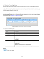
4.14 RMON .................................................................................................................................................... 320
4.14.1 RMON Statistics ............................................................................................................................................... 320
4.14.2 RMON Event .................................................................................................................................................... 322
4.14.3 RMON Event Log ............................................................................................................................................. 323
4.14.4 RMON Alarm .................................................................................................................................................... 324
4.14.5 RMON History .................................................................................................................................................. 327
4.14.6 RMON History Log ........................................................................................................................................... 328
4.15 Power over Ethernet ............................................................................................................................ 329
4.15.1 Long Reach Power over Ethernet Powered Device ......................................................................................... 330
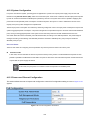
4.15.2 System Configuration ....................................................................................................................................... 331
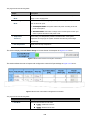
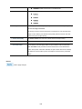
4.15.3 Power over Ethernet Configuration .................................................................................................................. 331
8
4.15.4 PoE Schedule .................................................................................................................................................. 334
4.15.5 PoE Alive Check Configuration ........................................................................................................................ 337
4.16 Maintenance ......................................................................................................................................... 339
4.16.1 Factory Default ................................................................................................................................................. 339
4.16.2 Reboot Switch .................................................................................................................................................. 339
4.16.3 Backup Manager .............................................................................................................................................. 340
4.16.4 Upgrade Manager ............................................................................................................................................ 341
4.16.5 Dual Image ....................................................................................................................................................... 342
5. SWITCH OPERATION ......................................................................................................... 343
5.1 Address Table ......................................................................................................................................... 343
5.2 Learning .................................................................................................................................................. 343
5.3 Forwarding & Filtering ........................................................................................................................... 343
5.4 Store-and-Forward ................................................................................................................................. 343
5.5 Auto-Negotiation .................................................................................................................................... 345
6. TROUBLESHOOTING ......................................................................................................... 346
APPENDIX A ............................................................................................................................ 348
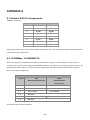
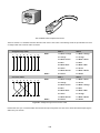
A.1 Switch's RJ45 Pin Assignments ........................................................................................................... 348
A.2 10/100Mbps, 10/100BASE-TX ................................................................................................................ 348
9
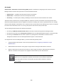
1. INTRODUCTION
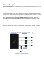
Thank you for purchasing IFS POC2502 Managed Switch, which comes with multiple POC female BNC connectors, Gigabit
Ethent copper and SFP fiber optic connectibility and robust layer 2 and layer 4 features. The description of this model is shown
below:
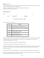
POC2502-8CXP-2T-2S 8-port Coax + 2-port 10/100/1000T + 2-port 100/1000X SFP PoE over Coaxial Managed Switch
POC2502-16CXP-2T-2S 16-port Coax + 2-port 10/100/1000T + 2-port 100/1000X SFP PoE over Coaxial Managed Switch
“POC Managed Switch” is used as an alternative name in this user’s manual.
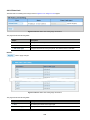
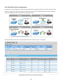
1.1 Packet Contents
Open the box of the POC Managed Switch and carefully unpack it. The box should contain the following items:
The Power Over Coax Managed Switch x 1
Quick Installation Guide x 1
Rubber Feet x 4
Power Cord x 1
RS232 to RJ45 Console Cable x 1
SFP Dust Cap x 2
BNC Female Dust Cap x 8 (POC2502-8CXP-2T-2S)
BNC Female Dust Cap x 16 (POC2502-16CXP-2T-2S)
Warning Sticker x 8 (POC2502-8CXP-2T-2S)
Warning Sticker x 16 (POC2502-16CXP-2T-2S)
Rack-mount Accessory Kit x 1
If any item is found missing or damaged, please contact your local reseller for replacement.
10
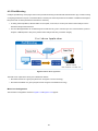
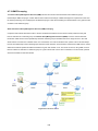
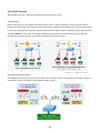
1.2 Product Description
Power Over Coax Solution enables all enterprises and network service providers to set up an IP infrastructure in a remote
location where 802.3af/at PoE compliant powered devices can receive both data and power via IFS switches, and IFS
POC2502 extenders and injectors over a long distance but not limited to the normal 100 meters.
Intelligent POC Switch on Coaxial-based Network
IFS POC2502 Managed Switch, a brand-new Multi-channel Power Over Coax Switch, features an extended Ethernet and PoE
networking of up to 1,000 meters over the existing coaxial cables going to multiple PoE IP cameras. It provides IPv6 / IPv4 dual
stack management and built-in L2/L4 Gigabit Switching engine along with multi-BNC ports with Long Reach PoE Injector
function, 2 Gigabit copper ports and 2 extra 100/1000BASE-X SFP fiber slots. As an advanced PoE switch, the IFS
POC2502 Managed Switch features intelligent PoE functions to improve the availability of critical applications. It provides a
quick, safe and cost-effective PoE network solution to upgrading the existing coaxial cable infrastructure from the analog
system to the HD IP surveillance system.
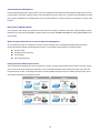
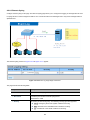
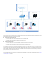
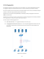
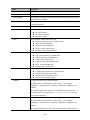
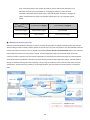
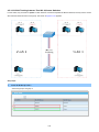
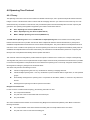
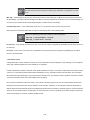
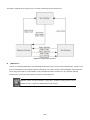
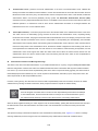
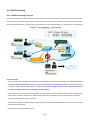
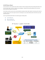
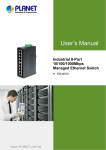
Multi-channel Long Reach Power over Ethernet
To support the enterprises in easily building a multi-channel and centrally-controlled Long Reach PoE system, the POC2502
works with the Long Reach PoE Extenders, POC252-1CX-1P, via its BNC ports being the Long Reach PoE injectors for all
connected POC Extenders. Each of the BNC port features long range data and power transmission for distance up to 1,000m
(3,280ft) over coaxial cable to the POC Extender, and another 100m over Ethernet cable to remote PoE IP camera, PoE
wireless AP or access control systems complied with 802.3af/at PoE.
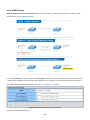
Typical POC to IP Camera Configuration
11
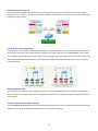
Centralized Power Management
IFS POC2502 Managed Switch eliminates the need for an additional remote site power while allowing a single power source to
provide power to both POC extenders and the PoE powered devices at long range. The Long Reach PoE capabilities provided
help to reduce installation time and deployment costs for network devices as a result of freeing from restrictions of power outlet
locations.
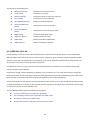
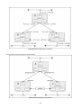
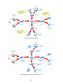
Daisy-chaining Multiple Nodes
IFS Long Reach PoE solution can easily build a power system for centrally-controlled IP cameras in a high availability network
infrastructure. It gives users the flexibility to expand small area network with BNC T-connector for sharing four nodes per port
when needed.
Built-in Unique PoE Functions for Powered Devices Management
As a managed PoE switch for surveillance, wireless and VoIP networks, the IFS POC2502 Managed Switch particularly
features the following special PoE Management functions to accomplish a highly-efficient Long Reach network:
PD Alive Check
Scheduled Power Recycling
PoE Schedule
PoE Usage Monitoring
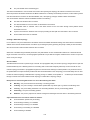
Intelligent Powered Device Alive Check
The IFS POC2502 Managed Switch can be configured to monitor connected PD (Powered Device) status in real time via ping
action. Once the PD stops working and responding, the IFS POC2502 Managed Switch will resume the PoE port power and
bring the PD back to work. It will greatly enhance the network reliability through the PoE port resetting the PD’s power source
and reducing administrator management burden.
12
Scheduled Power Recycling
The IFS POC2502 Managed Switch allows each of the connected PoE IP cameras or PoE wireless access points via the
POC252-1CX-1P to reboot at a specific time each week. Therefore, it will reduce the chance of IP camera or wireless AP crash
resulting from buffer overflow.
PoE Schedule for Energy Saving
Under the trend of energy saving worldwide and contributing to environmental protection, the IFS POC2502 Managed Switch
can effectively control the power supply besides its capability of giving high watts power. The “PoE schedule” function helps
you to enable or disable PoE power feeding for each PoE port during specified time intervals and it is a powerful function to help
SMBs or enterprises save power and money. It also increases security by powering off PDs that should not be in use during
non-business hours.
PoE Usage Monitoring
Via the power usage chart in the web management interface, the IFS POC2502 Managed Switch enables the administrator to
monitor the status of the power usage of the connected PDs in real time. Thus, it greatly enhances the management efficiency
of the facilities.
PoE Over-temperature Protection System
The over-temperature protection of the IFS POC2502 Managed Switch offers a safe and stable PoE operation by limiting the
output power in order to avoid destructive breakdown due to unexpected overheating.
13
Environment-friendly, Smart Fan Design for Silent Operation
The IFS POC2502 Managed Switch features a 19-inch metal housing, a low noise design and an effective ventilation system. It
supports the smart fan technology to automatically control the speed of the built-in fan to reduce noise and maintain the
temperature of the PoE switch for optimal power output capability. The IFS POC2502 Managed Switch is able to operate reliably,
stably and quietly in any environment without affecting its performance.
IPv6 / IPv4 Dual Stack
Supporting both IPv6 and IPv4 protocols, the IFS POC2502 Managed Switch the SMBs to step in the IPv6 era with the lowest
investment as its network facilities need not be replaced or overhauled if the IPv6 FTTx edge network is set up.
Robust Layer 2 Features
The IFS POC2502 Managed Switch can be programmed for advanced switch management functions such as dynamic port link
aggregation, 802.1Q VLAN and Q-in-Q VLAN, Multiple Spanning Tree Protocol (MSTP), Loop and BPDU Guard, IGMP
Snooping, and MLD Snooping. Via the link aggregation, the IFS POC2502 Managed Switch allows the operation of a
high-speed trunk to combine with multiple ports such as an 8Gbps fat pipe, and supports fail-over as well. Also, the Link Layer
Discovery Protocol (LLDP) is the Layer 2 Protocol included to help discover basic information about neighboring devices on the
local broadcast domain.
Efficient Traffic Control
The IFS POC2502 Managed Switch is loaded with robust QoS features and powerful traffic management to enhance services
to business-class data, voice, and video solutions. The functionality includes broadcast / multicast storm control, per port
bandwidth control, IP DSCP QoS priority and remarking. It guarantees the best performance for VoIP and video stream
transmission, and empowers the enterprises to take full advantage of the limited network resources.
Powerful Security
IFS IFS POC2502 Managed Switch offers comprehensive IPv4 / IPv6 Layer 2 to Layer 4 Access Control List (ACL) for
enforcing security to the edge. It can be used to restrict network access by denying packets based on source and destination IP
address, TCP/UDP ports or defined typical network applications. Its protection mechanism also comprises 802.1X port-based
user and device authentication, which can be deployed with RADIUS to ensure the port level security and block illegal users.
With the Protected Port function, communication between edge ports can be prevented to guarantee user privacy.
Furthermore, Port Security function allows limiting the number of network devices on a given port.
14
Advanced Network Security
The IFS POC2502 Managed Switch also provides DHCP Snooping, IP Source Guard and Dynamic ARP Inspection
functions to prevent IP snooping from attack and discard ARP packets with invalid MAC address. The network administrators
can now build highly-secured corporate networks with considerably less time and effort than before.
Friendly and Secure Management
For efficient management, the IFS POC2502 Managed Switch is equipped with console, Web, Telnet and SNMP management
interfaces. With the built-in Web-based management interface, the IFS POC2502 Managed Switch offers an easy-to-use,
platform-independent management and configuration facility. By supporting the standard Simple Network Management Protocol
(SNMP), the switch can be managed via any standard management software. For text-based management, the switch can be
accessed via Telnet and the console port. Moreover, the IFS POC2502 Managed Switch offers secure remote management by
supporting SSH, SSL and SNMP v3 connections which encrypt the packet content at each session.
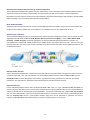
Flexibility and Long-distance Extension Solution
The IFS POC2502 Managed Switch provides two Gigabit TP interfaces supporting 10/100/1000BASE-T RJ45 copper to be
connected with surveillance network devices such as NVR, Video Streaming Server or NAS to facilitate surveillance
management. Or through another two dual-speed fiber SFP slots, it can connect with the 100BASE-FX /
1000BASE-SX/LX SFP (Small Form-factor Pluggable) fiber transceiver to uplink to backbone switch and monitoring center in
long distance. The distance can be extended from 550 meters to 2 kilometers (multi-mode fiber) and up to
10/20/30/40/50/70/120 kilometers (single-mode fiber or WDM fiber). The IFS POC2502 Managed Switch is well suited for
applications within the enterprise data centers and distributions.
Intelligent SFP Diagnosis Mechanism
The IFS POC2502 Managed Switch also supports SFP-DDM (Digital Diagnostic Monitor) function that can easily monitor
real-time parameters of the SFP for network administrator, such as optical output power, optical input power, temperature, laser
bias current and transceiver supply voltage.
15
1.3 How to Use This Manual
This User Manual is structured as follows:
Section 2, INSTALLATION
The section explains the functions of the Switch and how to physically install the POC Managed Switch.
Section 3, SWITCH MANAGEMENT
The section contains the information about the software function of the POC Managed Switch.
Section 4, WEB CONFIGURATION
The section explains how to manage the POC Managed Switch by Web interface.
Section 5, SWITCH OPERATION
The chapter explains how to do the switch operation of the POC Managed Switch.
Section 6, TROUBLESHOOTING
The chapter explains how to troubleshoot of the POC Managed Switch.
Appendix A
The section contains cable information of the POC Managed Switch.
1.4 Product Features
Physical Port
■ 100Mbps BNC female ports with Long Reach PoE Injector function
■ 2 10/100/1000BASE-T Gigabit RJ45 copper ports
■ 2 100/1000BASE-X mini-GBIC/SFP slots
■ RJ45 console interface for switch basic management and setup
Long Reach Power over Ethernet
■ Supports PoE power up to 36 watts for each PoE port
■ Remote power feeding up to 1 kilometer with low impedance 75Ω coaxial cable
■ Long Reach PoE Management
− Total Long Reach PoE power budget control
− Per port Long Reach PoE function enable/disable
− Long Reach PoE port power feeding priority
− Per Long Reach PoE port power limitation
− Long Reach PD alive check
− Long Reach PoE schedule
16
Layer 2 Features
■ Prevents packet loss with back pressure (half-duplex) and IEEE 802.3x pause frame flow control (full-duplex)
■ High performance Store and Forward architecture, broadcast storm control, runt/CRC filtering that eliminates
erroneous packets to optimize the network bandwidth
■ Supports VLAN
-
IEEE 802.1Q tagged VLAN
-
Provider Bridging (VLAN Q-in-Q) support (IEEE 802.1ad)
-
Protocol VLAN
-
Voice VLAN
-
Private VLAN
-
Management VLAN
-
GVRP
■ Supports Spanning Tree Protocol
-
STP (Spanning Tree Protocol)
-
RSTP (Rapid Spanning Tree Protocol)
-
MSTP (Multiple Spanning Tree Protocol)
-
STP BPDU Guard, BPDU Filtering and BPDU Forwarding
■ Supports Link Aggregation
− IEEE 802.3ad Link Aggregation Control Protocol (LACP)
− Cisco ether-channel (static trunk)
− Maximum 4 trunk groups, up to 4 ports per trunk group
■ Provides port mirror (many-to-1)
■ Loop protection to avoid broadcast loops
Quality of Service
■ Ingress / Egress rate limit per port bandwidth control
■ Storm control support
− Broadcast / Unknown unicast / Unknown multicast
■ Traffic classification
-
IEEE 802.1p CoS
-
ToS / DSCP / IP Precedence of IPv4/IPv6 packets
■ Strict priority and Weighted Round Robin (WRR) CoS policies
Multicast
■ Supports IGMP snooping v2 and v3
■ Supports MLD snooping v1, v2
■ IGMP querier mode support
■ IGMP snooping port filtering
■ MLD snooping port filtering
17
Security
■ Authentication
− IEEE 802.1x port-based network access authentication
− Built-in RADIUS client to co-operate with the RADIUS servers
− RADIUS / TACACS+ login user access authentication
■ Access Control List
− IPv4 / IPv6 IP-based ACL
− MAC-based ACL
■ MAC Security
− Static MAC
− MAC filtering
■ Port security for source MAC address entries filtering
■ DHCP snooping to filter untrusted DHCP messages
■ Dynamic ARP inspection discards ARP packets with invalid MAC address to IP address binding
■ IP source guard prevents IP spoofing attacks
■ DoS attack prevention
■ SSH / SSL
Management
■ IPv4 and IPv6 dual stack management
■ Switch management interface
-
Web switch management
Telnet command line interface
SNMP v1, v2c and v3
SSH / SSL secure access
■ User privilege levels control
■ Built-in Trivial File Transfer Protocol (TFTP) client
■ BOOTP and DHCP for IP address assignment
■ System maintenance
-
Firmware upload/download via HTTP / TFTP
Configuration upload/download through Web interface
Dual images
Hardware reset button for system reboot or reset to factory default
■ SNTP Network Time Protocol
■ Cable diagnostics
■ Link Layer Discovery Protocol (LLDP) and LLDP-MED
■ SNMP trap for interface linkup and linkdown notification
■ Event message logging to remote Syslog server
■ Four RMON groups (history, statistics, alarms and events)
■ IFS Smart Discovery utility
■ Smart fan with speed control
18
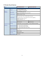
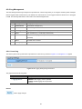
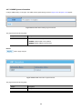
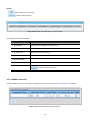
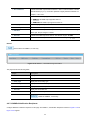
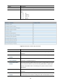
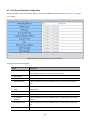
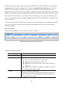
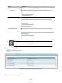
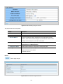
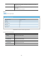
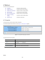
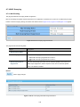
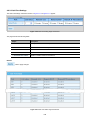
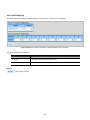
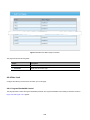
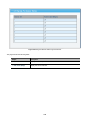
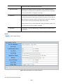
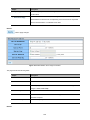
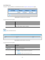
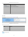
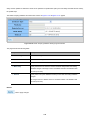
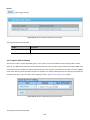
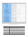
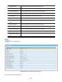
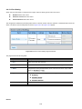
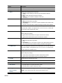
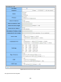
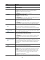
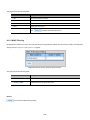
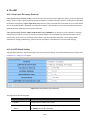
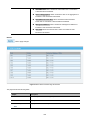
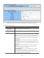
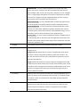
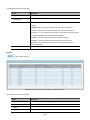
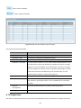
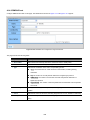
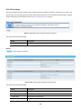
1.5 Product Specifications
Model
POC2502-8CXP-2T-2S
POC2502-16CXP-2T-2S
Hardware Specifications
Copper
Ethernet
Interfaces
Fiber Optic
Jumbo Frame
2 x 10/100/1000BASE-T RJ45
Auto-negotiation/ Auto-MDI/MDI-X
2 x 100/1000BASE-X SFP slot
Supports 100/1000Mbps dual mode and DDM
10Kbytes with GE1 to GE4
POC2502-8CXP-2T-2S: 8 x BNC female connectors
POC2502-16CXP-2T-2S:16 x BNC female connectors
Connectivity
Long Reach PoE over coaxial PSE (Power Source Equipment)
BNC center pole : DC+ / Hi
BNC shield : DC - / Lo
Power Output
Per port 54V DC, 36 watts max.
Per port 52V DC, 36 watts max.
Total POE Budget
240 watts (max.)
380 watts (max.)
Cabling
Coaxial cable: 75 ohm Low Impedance RG-6/U cable (Recommended)
Long Reach PoE
Max. 200m with PoE+ output (1,640ft.)
Interfaces
Maximum Distance
Max. 400m with PoE output (2,624ft.)
Max. 1000m with PoE output (3,280ft.)
Max. 1200m with data output only (3,937ft.)
Long Reach
Ethernet Standard
IEEE 1901
Modulation Type
Wavelet-OFDM
Security
128-bit AES encryption
Frequency Band
2 ~ 28MHz
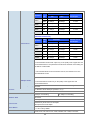
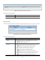
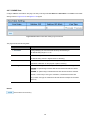
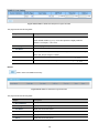
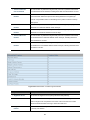
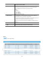
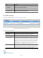
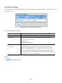
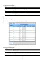
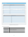
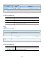
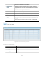
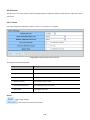
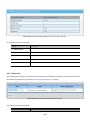
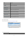
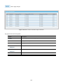
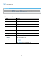
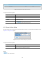
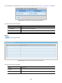
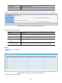
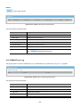
19
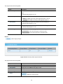
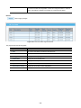
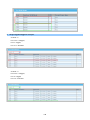
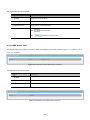
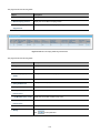
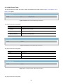
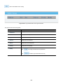
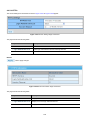
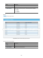
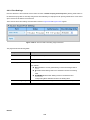
[POC2502-8CXP-2T-2S]
Cable
Distance
Data Rate*
POC252-1CX-1P
Type
TX**
RG6
91.8Mbps
81.1Mbps
22.9W
RG59
92.4Mbps
85.6Mbps
16.33W
400m
RG6
85.5Mbps
66.9Mbps
18.4W
600m
RG6
76.5Mbps
54.2Mbps
13.6W
800m
RG6
67.9Mbps
49.2Mbps
10.47W
1000m
RG6
26.6Mbps
25.6Mbps
8.45W
200m
RX**
PoE Output*
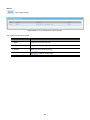
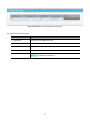
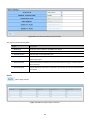
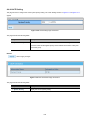
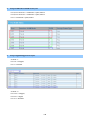
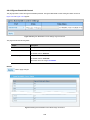
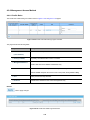
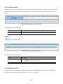
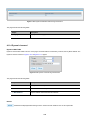
[POC2502-16CXP-2T-2S]
Cable
Distance
Data Rate*
POC252-1CX-1P
Type
TX**
RG6
87.1Mbps
77.6Mbps
19.9W
RG59
89.3Mbps
82.5Mbps
13.33W
400m
RG6
82.5Mbps
63.7Mbps
15.4W
600m
RG6
72.8Mbps
51.1Mbps
10.6W
800m
RG6
63.4Mbps
45.2Mbps
7.47W
1000m
RG6
20.2Mbps
19.8Mbps
5.45W
Performance
200m
RX**
PoE Output*
* The actual data rate and PoE output vary on the quality of the copper wire and
environmental factors. The performance result above is based on the testing via
the RG-6/U coaxial cable.
** TX: POC2502-8CXP-2T-2S to POC252-1CX-1P; RX: POC252-1CX-1P to
POC2502-8CXP-2T-2S.
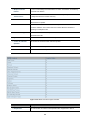
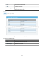
Up to 3 POC extenders within 1km RG-6/U coaxial cable*
Multiple Nodes
POC Compatibility
* The actual extender nodes vary on the quality of the copper wire and
environmental factors.
POC252-1CX-1P: 1-Port 10/100TX PoE PSE + 1-Port Coax Long Reach PoE
Extender
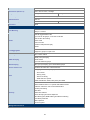
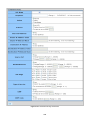
Console
1 x RS232-to-RJ45 serial port (115200, 8, N, 1)
Switch Architecture
Store-and-Forward
Switch Fabric
9.6Gbps / non-blocking
Address Table
8K entries
Shared Data Buffer
4.1 megabits
Flow Control
Reset Button
LED
11.2Gbps / non-blocking
IEEE 802.3x pause frame for full-duplex
Back pressure for half-duplex
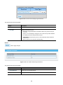
< 5 sec: System reboot
> 5 sec: Factory default
PWR, SYS, LNK, PoE-in-Use, 1000, LNK/ACK, Fan 1 Alert, Fan 2 Alert,
20
PoE PWR Alert
Dimensions (W x D x H)
440 x 300 x 44.5 mm, 1U height
Weight
4282g
Power Requirements
AC 100~240V, 50/60Hz, auto-sensing
ESD Protection
6KV DC
Power Consumption
270 watts / 926 BTU
Enclosure
Metal
4430g
495 watts / 1698 BTU
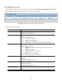
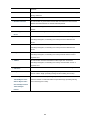
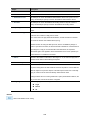
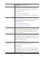
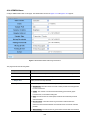
Layer 2 Functions
Port Mirroring
TX / RX / both
Many-to-1 monitor
802.1Q tagged-based VLAN
Up to 256 VLAN groups, out of 4094 VLAN IDs
802.1ad Q-in-Q tunneling
VLAN
Voice VLAN
Protocol VLAN
Private VLAN (Protected port)
GVRP
Link Aggregation
Spanning Tree Protocol
IEEE 802.3ad LACP and static trunk
Supports 4 groups of 4-port trunk
STP / RSTP / MSTP
IGMP (v2/v3) Snooping
IGMP Snooping
IGMP Querier
Up to 256 multicast groups
MLD Snooping
MLD (v1/v2) Snooping, up to 256 multicast groups
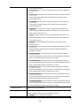
Access Control List
IPv4/IPv6 IP-based ACL / MAC-based ACL
8 mapping ID to 8 level priority queues
- Port number
- 802.1p priority
QoS
- 802.1Q VLAN tag
- DSCP field in IP packet
Traffic classification based, strict priority and WRR
IEEE 802.1X– Port-based authentication
Built-in RADIUS client to co-operate with RADIUS server
RADIUS / TACACS+ user access authentication
IP-MAC port binding
MAC filter
Security
Static MAC address
DHCP Snooping and DHCP Option 82
STP BPDU guard, BPDU filtering and BPDU forwarding
DoS attack prevention
ARP inspection
IP source guard
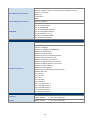
Management Functions
21
Web browser / Telnet / SNMP v1, v2c
Firmware upgrade by HTTP / TFTP protocol through Ethernet network
Basic Management Interfaces
Remote / Local Syslog
System log
LLDP protocol
SNTP
Secure Management Interfaces
SSH, SSL, SNMP v3
RFC 1213 MIB-II
RFC 1215 Generic Traps
RFC 1493 Bridge MIB
SNMP MIBs
RFC 2674 Bridge MIB Extensions
RFC 2737 Entity MIB (Version 2)
RFC 2819 RMON (1, 2, 3, 9)
RFC 2863 Interface Group MIB
RFC 3635 Ethernet-like MIB
Standards Conformance
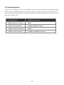
Regulation Compliance
FCC Part 15 Class A, CE
IEEE 1901 Broadband Power Line
IEEE 802.3 10BASE-T
IEEE 802.3u 100BASE-TX/100BASE-FX
IEEE 802.3z Gigabit SX/LX
IEEE 802.3ab Gigabit 1000T
IEEE 802.3x flow control and back pressure
IEEE 802.3ad port trunk with LACP
IEEE 802.1D Spanning Tree Protocol
IEEE 802.1w Rapid Spanning Tree Protocol
IEEE 802.1s Multiple Spanning Tree Protocol
IEEE 802.1p Class of Service
Standards Compliance
IEEE 802.1Q VLAN tagging
IEEE 802.1X Port Authentication Network Control
IEEE 802.1ab LLDP
RFC 768 UDP
RFC 793 TFTP
RFC 791 IP
RFC 792 ICMP
RFC 2068 HTTP
RFC 1112 IGMP version 1
RFC 2236 IGMP version 2
RFC 3376 IGMP version 3
RFC 2710 MLD version 1
RFC 3810 MLD version 2
Environment
Operating
Temperature:
Relative Humidity:
0 ~ 50 degrees C
5 ~ 95% (non-condensing)
Storage
Temperature:
Relative Humidity:
-10 ~ 70 degrees C
5 ~ 95% (non-condensing)
22
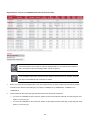
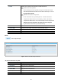
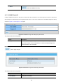
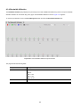
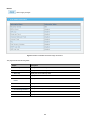
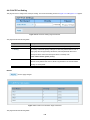
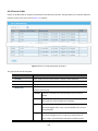
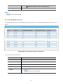
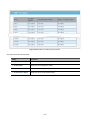
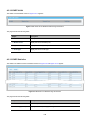
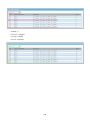
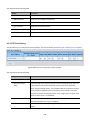
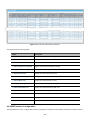
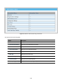
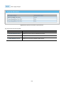
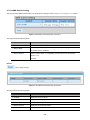
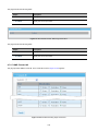
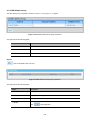
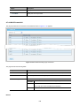
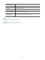
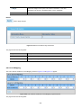
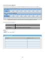
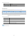
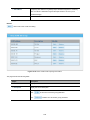
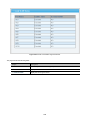
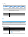
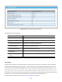
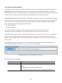
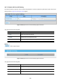
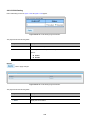
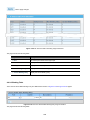
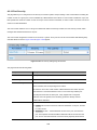
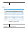
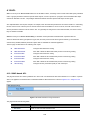
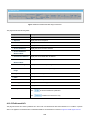
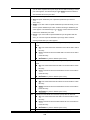
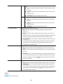
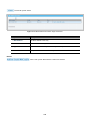
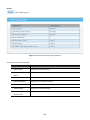
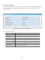
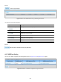
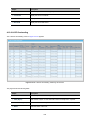
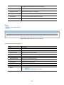
Additional PoE output vs cable type information:
RG-59 Bare Copper Coaxial Cable
Item
Coaxial Cable Length
POC252-1CX Maximum PoE Output (W)
No.
Feet
Meters
POC2502-8CXP
POC2502-16CXP
1
100
30
27.7
27.0
2
200
61
27.7
27.0
3
300
91
27.0
26.0
4
400
122
25.9
25.2
5
500
152
25.8
25.0
6
600
183
25.2
24.2
7
700
213
24.4
23.5
8
800
244
24.0
23.0
9
900
274
23.6
22.3
10
1000
305
22.9
21.8
11
1100
335
22.3
21.2
12
1200
366
21.8
20.6
13
1300
396
21.2
20.0
14
1400
427
20.7
19.8
15
1500
457
19.7
18.9
16
1600
488
19.3
18.5
17
1700
518
18.9
18.1
18
1800*
549*
18.2
18.0
19
1900*
579*
17.5
17.0
20
2000*
610*
17.0
16.1
21
2100*
640*
16.6
15.3
22
2200*
671*
15.7
14.7
23
2300*
701*
14.8
14.2
24
2400*
732*
14.4
13.8
25
2500*
762*
13.9
13.5
26
2600*
792*
13.8
13.0
27
2700*
823*
13.0
12.3
28
2800*
853*
12.6
12.0
29
2900*
884*
12.1
11.5
30
3000*
914*
11.7
11.0
31
3100*
945*
11.4
10.7
32
3200*
975*
10.7
10.3
33
3300*
1006*
10.3
10.0
Above PoE outputs are based on RG-59 Bare Copper, 10Ω/1000FT DC Resistance coaxial cable at 25°C operation.
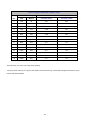
23
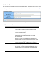
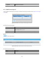
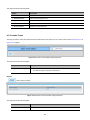
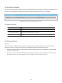
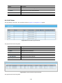
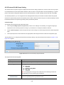
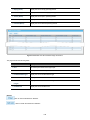
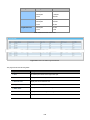
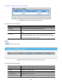
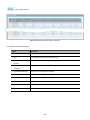
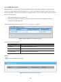
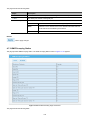
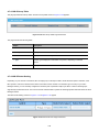
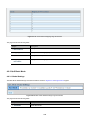
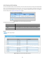
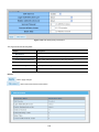
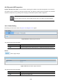
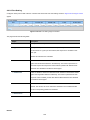
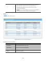
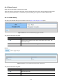
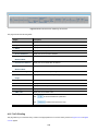
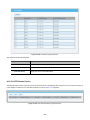
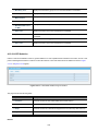
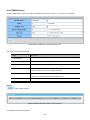
RG-59 Copper-Clad Steel Coaxial Cable
Item
Coaxial Cable Length
POC252-1CX Maximum PoE Output (W)
No.
Feet
Meters
POC2502-8CXP
POC2502-16CXP
1
100
30
26.1
24.4
2
200
61
25.4
24.0
3
300
91
22.4
21.4
4
400
122
19.8
19.1
5
500*
152*
14.3
13.6
6
600*
183*
12.8
12.1
7
700*
213*
10.6
10.5
8
800*
244*
9.5
10.1
9
900*
274*
9.3
8.7
10
1000*
305*
7.9
7.4
11
1100*
335*
7.1
6.7
12
1200*
366*
6.4
5.8
13
1300*
396*
5.5
5.3
14
1400*
427*
5.4
5.1
15
1500*
457*
4.9
4.6
Above PoE outputs are based on RG-59 CCS, 46Ω/1000FT DC Resistance coaxial cables at 25°C operation.
The PoE output may reduce 1W at high temp operating.
*The long coaxial cable may not support 720P/1080P camera because long coaxial cable has high DC Resistance which
reduces data rate/bandwidth.
24
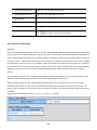
2. INSTALLATION
This section describes the hardware features and installation of the POC Managed Switch on the desktop or rack mount. For
easier management and control of the POC Managed Switch, familiarize yourself with its display indicators, and ports. Front
panel illustrations in this chapter display the unit LED indicators. Before connecting any network device to the POC Managed
Switch, please read this chapter completely.
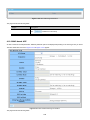
2.1 Hardware Description
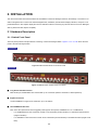
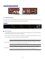
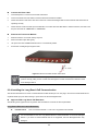
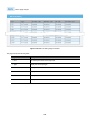
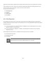
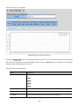
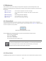
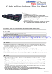
2.1.1 Switch Front Panel
The front panel provides a simple interface monitoring of the POC Managed Switch. Figure 2-1-1A ~ 2-1-1B shows the front
panel of the POC Managed Switch.
Front Panel
Figure 2-1-1A POC2502-8CXP-2T-2S Front Panel
Front Panel
Figure 2-1-1B POC2502-16CXP-2T-2S Front Panel
■ Long Reach PoE BNC Interface
BNC female port, RG59U/RG6 75Ω coaxial cable: Up to 1 kilometer. (Distance is based on cable impedance)
■ Gigabit TP Interface
10/100/1000BASE-T Copper, RJ45 Twist-Pair: Up to 100 meters.
■ 100/1000BASE-X SFP Slots
Each of the SFP (Small Form-factor Pluggable) slots supports dual-speed, 1000BASE-SX / LX or 100BASE-FX
-
For 1000BASE-SX/LX SFP transceiver module: From 550 meters (multi-mode fiber) to 10/30/50/70/120 kilometers
(single-mode fiber).
-
For 100BASE-FX SFP transceiver module: From 2 kilometers (multi-mode fiber) to 20/40/60 kilometers (single-mode
fiber).
25
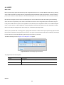
■ Console Port
The console port is a RJ45 port connector. It is an interface for connecting a terminal directly. Through the console port, it
provides rich diagnostic information including IP Address setting, factory reset, port management, link status and system
setting. Users can use the attached DB9 to RJ45 console cable in the package and connect to the console port on the
device. After the connection, users can run any terminal emulation program (Hyper Terminal, ProComm Plus, Telix,
Winterm and so on) to enter the startup screen of the device.
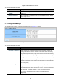
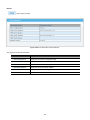
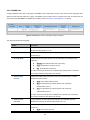
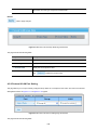
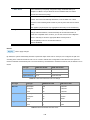
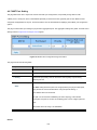
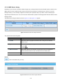
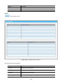
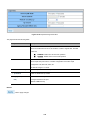
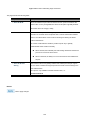
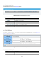
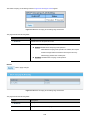
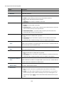
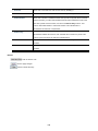
■ Reset Button
On the left of the front panel, the reset button is designed to reboot the POC Managed Switch without turning off and on the
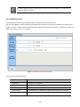
power. The following is the summary table of the Reset button functions:
Reset Button Pressed and Released
Function
< 5 sec: System Reboot
Reboot the POC Managed Switch.
Reset the POC Managed Switch to the Factory Default
configuration. The POC Managed Switch will then reboot and
load the default settings shown below:
> 5 sec: Factory Default
!
。
Default Username: admin
。
Default Password: admin
。
Default IP Address: 192.168.0.100
。
Subnet Mask: 255.255.255.0
。
Default Gateway: 192.168.0.254
For connection to POC Extenders only. NOT for direct camera
connections.
Note: Power at BNC ports are off by default. To enable POC power at each BNC connector, please consult the manual.
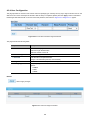
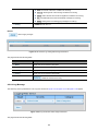
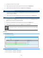
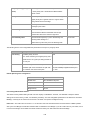
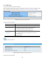
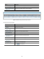
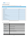
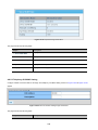
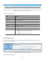
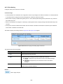
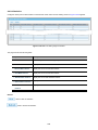
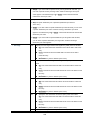
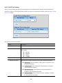
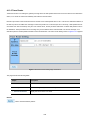
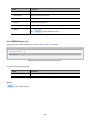
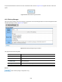
2.1.2 LED Indications
The front panel LEDs indicates instant status of port links, data activity and system power; it helps monitor and troubleshoot
when needed. Figure 2-1-2A ~ 2-1-2B shows the LED indications of these POC Managed Switches.
POC2502-8CXP-2T-2S LED Indication
Figure 2-1-2 POC2502-8CXP-2T-2S LED Panel
26
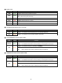
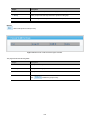
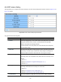
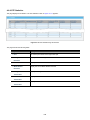
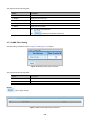
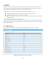
■ System / Alert
LED
Color
Function
PWR
Green
SYS
Green
FAN 1
Red
Lights to indicate that Fan 1 is down.
FAN 2
Red
Lights to indicate that Fan 2 is down.
FAN 3
Red
Lights to indicate that Fan 3 is down.
PWR
Red
Lights to indicate that the PoE Power is down.
Lights to indicate that the Switch has power.
Lights to indicate the system is working.
Off to indicate the system is booting.
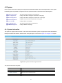
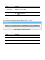
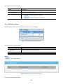
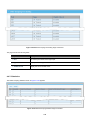
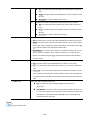
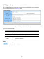
■ Long Reach PoE Interfaces (Port-1 to Port-8)
LED
Color
LNK
Green
PoE
Orange
Function
Lights: To indicate the link through that port is successfully established.
Lights: To indicate the port is providing 56VDC in-line power.
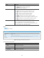
■ 10/100/1000BASE-T interfaces (GE1 to GE2)
LED
Color
LNK/ACT
Green
Function
Lights: To indicate the link through that port is successfully established.
Blink:
To indicate that the switch is actively sending or receiving data over that port.
Lights: To indicate that the port is operating at 1000Mbps.
1000
Orange
Lights: When LNK/ACT LED lights up, it indicates that the port is operating at 10/100Mbps.
Off:
When LNK/ACT LED is Off, it indicates that the port is linkdown.
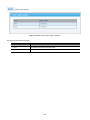
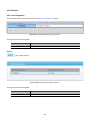
■ 1000BASE-SX/LX SFP interfaces (GE3 to GE4)
LED
Color
LNK/ACT
Green
Function
Lights: To indicate the link through that port is successfully established.
Blink:
To indicate that the switch is actively sending or receiving data over that port.
Lights: indicate that the port is operating at 1000Mbps.
1000
Orange
Lights: When LNK/ACT LED lights up, it indicates that the port is operating at 10/100Mbps.
Off:
When LNK/ACT LED is Off, it indicates that the port is linkdown.
27
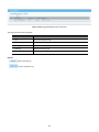
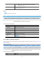
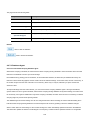
POC2502-16CXP-2T-2S LED Indication
Figure 2-1-2B POC2502-16CXP-2T-2S LED Panel
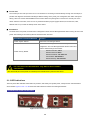
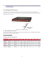
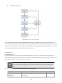
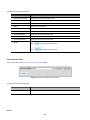
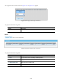
2.1.3 Switch Rear Panel
The rear panel of the POC Managed Switch indicates an AC inlet power socket, which accepts input power from 100 to 240V
AC, 50-60Hz. Figure 2-1-3 shows the rear panel of these POC Managed Switches
Rear Panel
Figure 2-1-3 Rear Panel of POC2502-8CXP-2T-2S / POC2502-16CXP-2T-2S
■ AC Power Receptacle
For compatibility with electric service in most areas of the world, the POC Managed Switch’s power supply automatically
adjusts to line power in the range of 100-240V AC and 50/60 Hz.
Plug the female end of the power cord firmly into the receptalbe on the rear panel of the POC Managed Switch. Plug the
other end of the power cord into an electrical outlet and the power will be ready.
The device is a power-required device, which means it will not work till it is powered. If your networks
Power Notice: should be active all the time, please consider using UPS (Uninterrupted Power Supply) for your device.
It will prevent you from network data loss or network downtime.
In some areas, installing a surge suppression device may also help to protect your POC Managed
Power Notice:
Switch from being damaged by unregulated surge or current to the POC Managed Switch.
28
2.2 Installing the Switch
This section describes how to install your POC Managed Switch and make connections to the POC Managed Switch. Please
read the following topics and perform the procedures in the order being presented. To install your POC Managed Switch on a
desktop or shelf, simply complete the following steps.
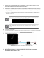
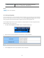
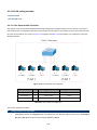
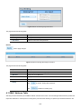
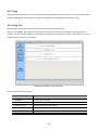
2.2.1 Desktop Installation
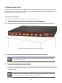
To install the POC Managed Switch on desktop or shelf, please follow these steps:
Step 1: Attach the rubber feet to the recessed areas on the bottom of the POC Managed Switch.
Step 2: Place the POC Managed Switch on the desktop or the shelf near an AC power source, as shown in Figure 2-1-4.
Figure 2-1-4 Place the POC Managed Switch on the desktop
Step 3: Keep enough ventilation space between the POC Managed Switch and the surrounding objects.
When choosing a location, please keep in mind the environmental restrictions discussed in Chapter 1,
Section 4 under specifications.
Step 4: Connect the POC Managed Switch to network devices.
Connect one end of a standard network cable to the 10/100/1000 RJ45 ports and standard coaxial cable to POC ports on
the front of the POC Managed Switch. Connect the other end of the cable to the network devices such as printer server,
workstation or router.
Connection to the POC Managed Switch requires UTP Category 5 network cabling with RJ45 tips. For
more information, please see the Cabling Specification in Appendix A.
29
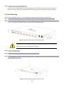
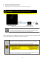
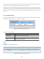
Step 5: Supply power to the POC Managed Switch.
Connect one end of the power cable to the POC Managed Switch. Connect the power plug of the power cable to a
standard wall outlet. When the POC Managed Switch receives power, the Power LED should remain solid Green.
2.2.2 Rack Mounting
To install the POC Managed Switch in a 19-inch standard rack, please follow the instructions described below.
Step 1: Place the POC Managed Switch on a hard flat surface, with the front panel positioned towards the front side.
Step 2: Attach the rack-mount bracket to each side of the POC Managed Switch with supplied screws attached to the package.
Figure 2-1-5 shows how to attach brackets to one side of the POC Managed Switch.
Figure 2-1-5 Attach Brackets to the POC Managed Switch.
You must use the screws supplied with the mounting brackets. Damage caused to the parts by
using incorrect screws would invalidate the warranty.
Step 3: Secure the brackets tightly.
Step 4: Follow the same steps to attach the second bracket to the opposite side.
Step 5: After the brackets are attached to the POC Managed Switch, use suitable screws to securely attach the brackets to the
rack, as shown in Figure 2-1-6.
Figure 2-1-6 Mounting POC Managed Switch in a Rack
30
Step 6: Proceeds with Steps 4 and 5 of session 2.2.1 Desktop Installation to connect the network cabling and supply power to
the POC Managed Switch.
2.2.3 Installing the SFP transceiver
The sections describe how to insert an SFP transceiver into an SFP slot. The SFP transceivers are hot-pluggable and
hot-swappable. You can plug in and out the transceiver to/from any SFP port without having to power down the POC Managed
Switch, as the Figure 2-1-7 shows.
Figure 2-1-7 Plug in the SFP transceiver
Approved IFS SFP Transceivers
IFS POC2502 Managed Switch supports both single mode and multi-mode SFP transceiver. The following list of approved IFS
SFP transceivers is correct at the time of publication:
SFP Transceiver Modules
Fast Ethernet Transceiver (100Base-X SFP)
31
Gigabit Ethernet Transceiver (1000BASX-LX-BX, Fiber Bi-Directional SFP)
It is recommended to use IFS SFP on the POC Managed Switch. If you insert an SFP transceiver
that is not supported, the POC Managed Switch will not recognize it.
In the installation steps below, this Manual uses Gigabit SFP transceiver as an example. However,
the steps for Fast Ethernet SFP transceiver are similar.
1.
Before we connect POC Managed Switch to the other network device, we have to make sure both sides of the SFP
transceivers are with the same media type, for example, 1000BASE-SX to 1000BASE-SX, 1000BASE-LX to
1000BASE-LX.
2.
Check whether the fiber-optic cable type matches with the SFP transceiver requirement.
To connect to 1000BASE-SX SFP transceiver, please use the multi-mode fiber cable with one side being the male
duplex LC connector type.
To connect to 1000BASE-LX SFP transceiver, please use the single-mode fiber cable with one side being the male
duplex LC connector type.
32
Connect the Fiber Cable
1.
Insert the duplex LC connector into the SFP transceiver.
2.
Connect the other end of the cable to a device with SFP transceiver installed.
3.
Check the LNK/ACT LED of the SFP slot on the front of the POC Managed Switch. Ensure that the SFP transceiver is
operating correctly.
4.
Check the Link mode of the SFP port if the link fails. To function with some fiber-NICs or media converters, user has to set
the port Link mode to “1000 Force” or “100 Force”.
Remove the Transceiver Module
1.
Make sure there is no network activity anymore.
2.
Remove the fiber-optic cable gently.
3.
Lift up the lever of the MGB module and turn it to a horizontal position.
4.
Pull out the module gently through the lever.
Figure 2-1-8 How to Pull Out the SFP Transceiver
Never pull out the module without lifting up the lever of the module and turning it into a horizontal
position. Directly pulling out the module could damage the module and the SFP module slot of the
POC Managed Switch.
2.2.4 Installing the Long Reach PoE Communication
The sections describe how to insert a coaxial cable into a BNC female port. You can plug in and out the coaxial cable to/from
any BNC female port port without having to power down the POC Managed Switch.
Approved IFS Long Reach PoE Extenders
The following list of approved IFS Long Reach PoE extenders is correct at the time of publication:
Long Reach Ethernet Coaxial Extenders
POC252-1CX-1P
1-Port 10/100TX PoE PSE + 1-Port Coax Long Reach PoE Extender
It is recommended to use IFS Long Reach Ethernet coaxial extenders on the POC Managed
Switch. If you insert a coaxial extender that is not supported, the POC Managed Switch may
damage it.
33
1.
Before we connect POC Managed Switch to the other network device, we have to make sure both sides of the Long
Reach Ethernet coaxial extender / transceiver are with the same media type.
2.
Check whether the coaxial cable type matches with the Long Reach Ethernet coaxial extender / transceiver requirement.
To connect to POC Managed Switch, please use the coaxial cable with 75Ω BNC plug with one side being the BNC
plug connector type.
To connect to Long Reach Ethernet coaxial extenders, please use the coaxial cable with one side being the 75Ω
BNC plug connector type.
Because there are various resistance values in the category of RG-59/U or RG-6/U cables, please
take care of the conditions of the resistance value of cables as follows:
Coaxial Cable Type
RG-59/U
Less than 30Ω/1000 ft.
RG-6/U
Less than 12Ω/1000 ft
In the installation steps below, this Manual uses Long Reach Ethernet coaxial extender as an
example.
Connect the Coaxial Cable
1.
Insert the coaxial cable with one side being the 75Ω BNC plug connector into the Long Reach Ethernet coaxial interface.
2.
Connect the other end of the cable to a device with Long Reach Ethernet coaxial extender installed.
3.
Tighten the BNC male connector gently.
Figure 2-1-8 How to insert the coaxial cable from POC Managed Switch
4.
Enable Long Reach Power over Ethernet function for the all POC ports from WebUI
5.
We suggest that all unused ports be turned off, as output voltage will be at the BNC connector output
And should have BNC cap installed for safety.
34
6.
Check the LNK LED of the Long Reach Power over Ethernet interface on the front of the POC POC Managed Switch.
Ensure that the Long Reach Power over Ethernet interface is operating correctly.
35
Remove the connected the Coaxial Cable
1.
Make sure there is no network activity anymore.
2.
Disable Long Reach Power over Ethernet function for the all POC ports from WebUI.
3.
LoosenFor
the BNC
male connector
gently.
connection
to POC
Extenders only. NOT for direct camera
!
connections.
Pull out the coaxial cable gently.
4.
Note: Power at BNC ports are off by default. To enable POC power at each BNC connector, please consult the manual.
Figure 2-1-8 How to pull out the coaxial cable from POC Managed Switch
Never pull out the coaxial cable without disabling Long Reach Power over Ethernet function for the
port from WebUI. Directly pulling out the coaxial cable could damage the Long Reach Ethernet
coaxial extender and the BNC female connector of the POC Managed Switch.
If you are uninstalling a port, we suggest that you turn that port off as voltage will be live at the output of the BNC
connector and place BNC cap that shipped with unit back on to open BNC.
1. The package contains eight warning stickers, which should be stuck on the coaxial cable
connector before using IFS POC2502 Managed Switch and POC extender. If connected with
non-IFS POC2502 extender equipment, it might cause damage to the equipment.
2. After the POC PoE port is enabled, the pin center of the coaxial cable has electricity. Do not touch
the pin center or connect this end to any non- IFS POC2502 equipment.
36
!
For connection to POC Extenders only. NOT for direct camera
connections.
Note: Power at BNC ports are off by default. To enable POC power at each BNC connector, please consult the manual.
To Disable unused ports or all ports.
37
3. SWITCH MANAGEMENT
This chapter explains the methods that you can use to configure management access to the POC Managed Switch. It describes
the types of management applications and the communication and management protocols that deliver data between your
management device (workstation or personal computer) and the system. It also contains information about port connection
options.
This chapter covers the following topics:
Requirements
Management Access Overview
Administration Console Access
Web Management Access
SNMP Access
Standards, Protocols, and Related Reading
3.1 Requirements
Workstations running Windows 2000/XP, 2003, Vista/7/8, 2008, MAC OS9 or later, Linux, UNIX or other platforms
are compatible with TCP/IP protocols.
Workstation is installed with Ethernet NIC (Network Interface Card)
Serial Port connect (Terminal)
• The above PC with COM Port (DB9 / RS232) or USB-to-RS232 converter
Ethernet Port connection
• Network cables -- Use standard network (UTP) cables with RJ45 connectors.
The above Workstation is installed with Web browser and JAVA runtime environment plug-in
It is recommended to use Internet Explore 8.0 or above to access POC Managed Switch.
38
3.2 Management Access Overview
The POC Managed Switch gives you the flexibility to access and manage it using any or all of the following methods:
An administration console
Web browser interface
An external SNMP-based network management application
The administration console and Web browser interface support are embedded in the POC Managed Switch software and are
available for immediate use. Each of these management methods has their own advantages. Table 3-1 compares the three
management methods.
Method
Console
Advantages
Disadvantages
• No IP address or subnet needed
• Must be near the switch or use dial-up
• Text-based
connection
• Telnet functionality and HyperTerminal
• Not convenient for remote users
• Modem connection may prove to be unreliable
built into Windows
95/98/NT/2000/ME/XP operating
or slow
systems
• Secure
Web Browser
• Ideal for configuring the switch remotely
• Compatible with all popular browsers
• Security can be compromised (hackers need
only know the IP address and subnet mask)
• Can be accessed from any location
• May encounter lag times on poor connections
• Most visually appealing
SNMP Agent
• Communicates with switch functions at
• Requires SNMP manager software
• Least visually appealing of all three methods
the MIB level
• Based on open standards
• Some settings require calculations
• Security can be compromised (hackers only
need to know the community name)
Table 3-1 Comparison of Management Methods
39
3.3 Administration Console
The administration console is an internal, character-oriented, and command line user interface for performing system
administration such as displaying statistics or changing option settings. Using this method, you can view the administration
console from a terminal, personal computer, Apple Macintosh, or workstation connected to the POC Managed Switch's console
port.
Figure 3-1-1: Console Management
Direct Access
Direct access to the administration console is achieved by directly connecting a terminal or a PC equipped with a
terminal-emulation program (such as HyperTerminal) to the POC Managed Switch console (serial) port. When using this
management method, a straight RS232 to RJ45 cable is required to connect the switch to the PC. After making this
connection, configure the terminal-emulation program to use the following parameters:
The default parameters are:
115200 bps
8 data bits
No parity
1 stop bit
Figure 3-1-2: Terminal Parameter Settings
You can change these settings, if desired, after you log on. This management method is often preferred because you can
remain connected and monitor the system during system reboots. Also, certain error messages are sent to the serial port,
40
regardless of the interface through which the associated action was initiated. A Macintosh or PC attachment can use any
terminal-emulation program for connecting to the terminal serial port. A workstation attachment under UNIX can use an
emulator such as TIP.
3.4 Web Management
The POC Managed Switch offers management features that allow users to manage the POC Managed Switch from anywhere
on the network through a standard browser such as Microsoft Internet Explorer. After you set up your IP address for the switch,
you can access the POC Managed Switch's Web interface applications directly in your Web browser by entering the IP address
of the POC Managed Switch.
Figure 3-1-3 Web Management
You can then use your Web browser to list and manage the POC Managed Switch configuration parameters from one central
location, just as if you were directly connected to the POC Managed Switch's console port. Web Management requires either
Microsoft Internet Explorer 8.0 or later, Google Chrome, Safari or Mozilla Firefox 1.5 or later.
Figure 3-1-4 Web Main Screen of POC Managed Switch
41
3.5 SNMP-based Network Management
You can use an external SNMP-based application to configure and manage the POC Managed Switch, such as SNMPc
Network Manager, HP Openview Network Node Management (NNM) or What’s Up Gold. This management method requires
the SNMP agent on the switch and the SNMP Network Management Station to use the same community string. This
management method, in fact, uses two community strings: the get community string and the set community string. If the
SNMP Net-work management Station only knows the set community string, it can read and write to the MIBs. However, if it only
knows the get community string, it can only read MIBs. The default gets and sets community strings for the POC Managed
Switch are public.
Figure 3-1-5 SNMP management
3.6 IFS Smart Discovery Utility
For easily listing the POC Managed Switch in your Ethernet environment, the IFS Smart Discovery Utility from user’s manual
CD-ROM is an ideal solution. The following installation instructions are to guide you to running the IFS Smart Discovery Utility.
1.
Deposit the IFS Smart Discovery Utility in administrator PC.
2.
Run this utility as the following screen appears.
Figure 3-1-6: IFS Smart Discovery Utility Screen
42
If there are two LAN cards or above in the same administrator PC, choose a different LAN card
by using the “Select Adapter” tool.
3.
Press the “Refresh” button for the currently connected devices in the discovery list as the screen shows below:
Figure 3-1-7: IFS Smart Discovery Utility Screen
1.
This utility shows all necessary information from the devices, such as MAC Address, Device Name, firmware version and
Device IP Subnet address. It can also assign new password, IP subnet address and description to the devices.
2.
After setup is completed, press the “Update Device”, “Update Multi” or “Update All” button to take effect. The meaning
of the 3 buttons above are shown below:
Update Device: use the current setting on one single device.
Update Multi: use the current setting on multi-devices.
Update All: use the current setting on whole devices in the list.
The same functions mentioned above also can be found in “Option” tools bar.
3.
To click the “Control Packet Force Broadcast” function, it allows you to assign a new setting value to the Web Smart
Switch under a different IP subnet address.
4.
Press the “Connect to Device” button and the Web login screen appears in Figure 3-1-4.
5.
Press the “Exit” button to shut down the IFS Smart Discovery Utility.
43
4. WEB CONFIGURATION
This section introduces the configuration and functions of the Web-based management.
About Web-based Management
The POC Managed Switch offers management features that allow users to manage the POC Managed Switch from anywhere
on the network through a standard browser such as Microsoft Internet Explorer.
The Web-based Management supports Internet Explorer 8.0. It is based on Java Applets with an aim to reduce network
bandwidth consumption, enhance access speed and present an easy viewing screen.
By default, IE8.0 or later version does not allow Java Applets to open sockets. The user has to
explicitly modify the browser setting to enable Java Applets to use network ports.
The POC Managed Switch can be configured through an Ethernet connection, making sure the manager PC must be set on the
same IP subnet address as the POC Managed Switch.
For example, the default IP address of the POC Managed Switch is 192.168.0.100, then the manager PC should be set at
192.168.0.x (where x is a number between 1 and 254, except 100), and the default subnet mask is 255.255.255.0.
If you have changed the default IP address of the POC Managed Switch to 192.168.1.1 with subnet mask 255.255.255.0 via
console, then the manager PC should be set at 192.168.1.x (where x is a number between 2 and 254) to do the relative
configuration on manager PC.
Figure 4-1-1 Web Management
1.
Logging on the switch
Use Internet Explorer 8.0 or above Web browser. Enter the factory-default IP address to access the Web interface. The
factory-default IP address is as follows:
http://192.168.0.100
44
2.
When the following login screen appears, please enter the default username "admin" with password “admin” (or the
username/password you have changed via console) to login the main screen of POC Managed Switch. The login screen
in Figure 4-1-2 appears.
Figure 4-1-2 Login screen
Default User Name: admin
Default Password: admin
After entering the username and password, the main screen appears as Figure 4-1-3.
Figure 4-1-3 Default Main Page
Now, you can use the Web management interface to continue the switch management or manage the POC Managed Switch by
Web interface. The Switch Menu on the left of the web page lets you access all the commands and statistics the POC Managed
45
Switch provides.
It is recommended to use Internet Explore 8.0 or above to access POC Managed Switch.
The changed IP address takes effect immediately after clicking on the Save button. You need to
use the new IP address to access the Web interface.
For security reason, please change and memorize the new password after this first setup.
Only accept command in lowercase letter under Web interface.
46
4.1 Main Web Page
The POC Managed Switch provides a Web-based browser interface for configuring and managing it. This interface allows you
to access the POC Managed Switch using the Web browser of your choice. This chapter describes how to use the POC
Managed Switch’s Web browser interface to configure and manage it.
Main Functions Menu
POC Port Link Status
Copper Port Link Status
SFP Port Link Status
Figure 4-1-4 Main Page
Panel Display
The Web agent displays an image of the POC Managed Switch’s ports. The Mode can be set to display different information for
the ports, including Link up or Link down. Clicking on the image of a port opens the Port Statistics page.
The port states are illustrated as follows:
State
Disabled
Down
Link
POC Ports
RJ45 Ports
SFP Ports
Main Menu
Using the onboard Web agent, you can define system parameters, manage and control the POC Managed Switch, and all its
ports, or monitor network conditions. Via the Web-Management, the administrator can set up the POC Managed Switch by
47
selecting the functions those listed in the Main Function. The screen in Figure 4-1-5 appears.
Figure 4-1-5 POC Managed Switch Main Functions Menu
Buttons
: Click to save changes or reset to default.
: Click to logout the POC Managed Switch.
: Click to reboot the POC Managed Switch.
: Click to refresh the page.
4.1.1 Save Button
This save button allows save the running / startup / backup configuration or reset switch in default parameter. The screen in
Figure 4-1-6 appears.
48
Figure 4-1-6 Save Button Screenshot
The page includes the following fields:
Object
Description
• Save Confiuration to
Click to save the configuration. For more detailed information, please refer to
FLASH
• Restore to Default
chapter 4.1.2
Click to reset switch in default parameter. For more detailed information, please
refer to chapter 4.15.1
4.1.2 Configuration Manager
The system file folder contains configuration settings. The screen in Figure 4-1-7 appears.
Figure 4-1-7 Save Button Screenshot
The page includes the following fields:
Object
Description
• Running Configuration
Refers to the running configuration sequence use in the switch. In switch, the
running configuration file stores in the RAM. In the current version, the running
configuration sequence running-config can be saved from the RAM to FLASH by
saving “Source File = Running Configuration” to “Destination File = Startup
Configuration”, so that the running configuration sequence becomes the startup
configuration file, which is called configuration save. To prevent illicit file upload
and easier configuration, switch mandates the name of running configuration file
to be running-config.
• Startup Configuration
Refers to the configuration sequence used in switch startup. Startup
configuration file stores in nonvolatile storage, corresponding to the so-called
configuration save. If the device supports multi-config file, name the configuration
file to be .cfg file, the default is startup.cfg. If the device does not support
multi-config file, mandates the name of startup configuration file to be
startup-config.
49
• Backup Configuration
The backup configuration is empty in FLASH; please save the backup
configuration first by “Maintenance > Backup Manager”.
Buttons
: Click to save configuration.
4.1.2.1 Saving Configuration
In the POC Managed Switch, the running configuration file stores in the RAM. In the current version, the running configuration
sequence of running-config can be saved from the RAM to FLASH by ”Save Configurations to FLASH” function, so that the
running configuration sequence becomes the startup configuration file, which is called configuration save.
To save all applied changes and set the current configuration as a startup configuration. The startup-configuration file will be
loaded automatically across a system reboot.
1.
Click ”Save > Save Configurations to FLASH” to login the “Configuration Manager” page.
2.
Select “Source File = Running Configuration” and “Destination File = Startup Configuration”.
3.
Press the “Apply” button to save running configuration to start up configuration.
50
4.2 System
Use the System menu items to display and configure basic administrative details of the POC Managed Switch. Under System
the following topics are provided to configure and view the system information. This section has the following items:
■ System Information
The switch system information is provided here.
■ IP Configurations
Configure the switch-managed IP information on this page.
■ IPv6 Configuration
Configure the switch-managed IPv6 information on this page.
■ User Configuration
Configure new user name and password on this page.
■ Time Settings
Configure SNTP on this page.
■ Log Management
The switch log information is provided here.
■ SNMP Management
Configure SNMP on this page.
4.2.1 System Information
The System Info page provides information for the current device information. System Info page helps a switch administrator to
identify the hardware MAC address, software version and system uptime. The screens in Figure 4-2-1 & Figure 4-2-2 appear.
Figure 4-2-1 System Information Page Screenshot
The page includes the following fields:
Object
Description
• System Name
Display the current system name
• System Location
Display the current system location
• System Contact
Display the current system contact
51
• MAC Address
The MAC address of this POC Managed Switch.
• IP Address
The IP address of this POC Managed Switch.
• Subnet Mask
The subnet mask of this POC Managed Switch.
• Gateway
The gateway of this POC Managed Switch.
• Loader Version
The loader version of this POC Managed Switch.
• Loader Date
The loader date of this POC Managed Switch.
• Firmware Version
The firmware version of this POC Managed Switch.
• Firmware Date
The firmware date of this POC Managed Switch.
• System Object ID
The system object ID of the POC Managed Switch.
• System Up Time
The period of time the device has been operational.
• PCN/HW Version
The hardware version of this POC Managed Switch.
Buttons
: Click to edit parameter.
4.2.2 IP Configurations
The IP Configuration includes the IP Address, Subnet Mask and Gateway. The configured column is used to view or change the
IP configuration. Fill out the IP Address, Subnet Mask and Gateway for the device. The screens in Figure 4-2-2 & Figure 4-2-3
appear.
Figure 4-2-2 IP Address Setting Page Screenshot
The page includes the following fields:
Object
Description
52
• Mode
Indicates the IP address mode operation. Possible modes are:
Static: Enable NTP mode operation.
When enabling NTP mode operation, the agent forwards and transfers
NTP messages between the clients and the server when they are not on
the same subnet domain.
DHCP: Enable DHCP client mode operation.
Enable the DHCP client by checking this box. If DHCP fails and the
configured IP address is zero, DHCP will retry. If DHCP fails and the
configured IP address is non-zero, DHCP will stop and the configured IP
settings will be used. The DHCP client will announce the configured
System Name as hostname to provide DNS lookup.
• IP Address
Provide the IP address of this switch in dotted decimal notation.
• Subnet Mask
Provide the subnet mask of this switch in dotted decimal notation.
• Gateway
Provide the IP address of the router in dotted decimal notation.
• DNS Server 1/2
Provide the IP address of the DNS Server in dotted decimal notation.
Buttons
: Click to apply changes.
Figure 4-2-3 IP Information Page Screenshot
The page includes the following fields:
Object
Description
• DHCP State
Display the current DHCP state.
• IP Address
Display the current IP address.
• Subnet Mask
Display the current subnet mask.
• Gateway
Display the current gateway.
• DNS Server 1/2
Display the current DNS server.
53
4.2.3 IPv6 Configuration
The IPv6 Configuration includes Auto Configuration, IPv6 Address and Gateway. The configured column is used to view or
change the IPv6 configuration. Fill out the Auto Configuration, IPv6 Address and Gateway for the device. The screens in Figure
4-2-4 & Figure 4-2-5 appear.
Figure 4-2-4 IPv6 Address Setting Page Screenshot
The page includes the following fields:
Object
Description
• Auto Configuration
Enable IPv6 auto-configuration by checking this box.
If it fails, the configured IPv6 address is zero. The router may delay responding to
a router solicitation for a few seconds; the total time needed to complete
auto-configuration can be significantly longer.
• IPv6 Address
Provide the IPv6 address of this switch.
IPv6 address is in 128-bit records represented as eight fields of up to four
hexadecimal digits with a colon separating each field (:). For example,
'fe80::215:c5ff:fe03:4dc7'.
The symbol '::' is a special syntax that can be used as a shorthand way of
representing multiple 16-bit groups of contiguous zeros; but it can only appear
once. It also uses the following legally IPv4 address. For example, '::192.1.2.34'.
Provide the IPv6 Prefix of this switch. The allowed range is 1 through 128.
• Gateway
Provide the IPv6 gateway address of this switch.
• DHCPv6 Client
To enable this POC Managed Switch to accept a configuration from a Dynamic
Host Configuration Protocol version 6 (DHCPv6) server. By default, the POC
Managed Switch does not perform DHCPv6 client actions. DHCPv6 clients
request the delegation of long-lived prefixes that they can push to individual local
hosts.
54
Buttons
: Click to apply changes.
Figure 4-2-5 IPv6 Information Page Screenshot
The page includes the following fields:
Object
Description
• Auto Configuration
Display the current auto configuration state
• IPv6 In Use Address
Display the current IPv6 in-use address
• IPv6 In Use Router
Display the current in-use gateway
• IPv6 Static Address
Display the current IPv6 static address
• IPv6 Static Router
Display the current IPv6 static gateway
• DHCPv6 Client
Display the current DHCPv6 client status
55
4.2.4 User Configuration
This page provides an overview of the current users and privilege type. Currently the only way to login as another user on the
Web server is to close and reopen the browser. After the setup is completed, please press the “Apply” button to take effect.
Please login Web interface with a new user name and password; the screens in Figure 4-2-6 & Figure 4-2-7 appear.
Figure 4-2-6 Local User Information Page Screenshot
The page includes the following fields:
Object
Description
• Username
The name identifying the user.
Maximum length: 32 characters;
Maximum number of users: 8
• Password Type
The password type for the user.
• Password
Enter the user’s new password here.
(Range: 0-32 characters plain text, case sensitive)
• Retype Password
Please enter the user’s new password here again to confirm.
• Privilege Type
The privilege type for the user.
Options:
• Admin
• User
• Other
Buttons
: Click to apply changes.
Figure 4-2-7 Local User Page Screenshot
56
The page includes the following fields:
Object
Description
• Username
Display the current username
• Password Type
Display the current password type
• Privilege Type
Display the current privilege type
• Modify
Click to modify the local user entry
: Delete the current user
4.2.5 Time Settings
4.2.5.1 System Time
Configure SNTP on this page.
SNTP is an acronym for Simple Network Time Protocol, a network protocol for synchronizing the clocks of computer systems.
You can specify SNTP Servers and set GMT Time zone. The SNTP Configuration screens in Figure 4-2-8 & Figure 4-2-9
appear.
Figure 4-2-8 SNTP Setup Page Screenshot
The page includes the following fields:
Object
Description
• Enable SNTP
Enabled: Enable SNTP mode operation.
When enabling SNTP mode operation, the agent forwards and transfers
57
SNTP messages between the clients and the server when they are not
on the same subnet domain.
Disabled: Disable SNTP mode operation.
• Manual Time
To set time manually.
Year - Select the starting Year.
Month - Select the starting month.
Day - Select the starting day.
Hours - Select the starting hour.
Minutes - Select the starting minute.
Seconds - Select the starting seconds.
• Time Zone
Allows to select the time zone according to the current location of switch.
• Daylight Saving Time
This is used to set the clock forward or backward according to the configurations
set below for a defined Daylight Saving Time duration. Select 'Disable' to disable
the Daylight Saving Time configuration. Select 'Recurring' and configure the
Daylight Saving Time duration to repeat the configuration every year. Select
'Non-Recurring' and configure the Daylight Saving Time duration for single time
configuration. (Default : Disabled ).
• Daylight Saving Time
Offset
• Recurring From
Enter the number of minutes to add during Daylight Saving Time. ( Range: 1 to
1440 )
• Week - Select the starting week number.
• Day - Select the starting day.
• Month - Select the starting month.
• Hours - Select the starting hour.
• Minutes - Select the starting minute.
• Recurring To
• Week - Select the starting week number.
• Day - Select the starting day.
• Month - Select the starting month.
• Hours - Select the starting hour.
• Minutes - Select the starting minute.
• Non-recurring From
• Week - Select the starting week number.
• Day - Select the starting day.
• Month - Select the starting month.
• Hours - Select the starting hour.
• Minutes - Select the starting minute.
• Non-recurring To
• Week - Select the starting week number.
• Day - Select the starting day.
• Month - Select the starting month.
• Hours - Select the starting hour.
• Minutes - Select the starting minute.
58
Buttons
: Click to apply changes.
Figure 4-2-9 Time Information Page Screenshot
The page includes the following fields:
Object
Description
• Current Data/Time
Display the current data/time
• SNTP
Display the current SNTP state
• Time Zone
Display the current time zone
• Daylight Saving Time
Display the current daylight saving time state
• Daylight Saving Time
Display the current daylight saving time offset state
Offset
• From
Display the current daylight saving time from
• To
Display the current daylight saving time to
59
4.2.5.2 SNTP Server Settings
The SNTP Server Configuration screens in Figure 4-2-10 & Figure 4-2-11 appear.
Figure 4-2-10 SNTP Setup Page Screenshot
The page includes the following fields:
Object
Description
• SNTP Server Address
Type the IP address or domain name of the SNTP server
• Server Port
Type the port number of the SNTP
Buttons
: Click to apply changes.
Figure 4-2-11 SNTP Server Information Page Screenshot
The page includes the following fields:
Object
Description
• SNTP Server Address
Display the current SNTP server address
• Server Port
Display the current SNTP server port
60
4.2.6 Log Management
The POC Managed Switch log management is provided here. The local logs allow you to configure and limit system messages
that are logged to flash or RAM memory. The default is for event levels 0 to 3 to be logged to flash and levels 0 to 6 to be logged
to RAM. The following table lists the event levels of the POC Managed Switch:
Level
Severity Name
Description
7
Debug
Debugging messages
6
Informational
Informational messages only
5
Notice
Normal but significant condition, such as cold start
4
Warning
Warning conditions (e.g., return false, unexpected return)
3
Error
Error conditions (e.g., invalid input, default used)
2
Critical
Critical conditions (e.g., memory allocation, or free memory error - resource
exhausted)
1
Alert
Immediate action needed
0
Emergency
System unusable
4.2.6.1 Local Log
The switch system local log information is provided here. The local Log screens in Figure 4-2-12 & Figure 4-2-13 appear.
Figure 4-2-12 Logging Settings Page Screenshot
The page includes the following fields:
Object
Description
• Logging Service
Enabled: Enable logging service operation.
Disabled: Disable logging service operation.
Buttons
: Click to apply changes.
61
Figure 4-2-13 Logging Information Page Screenshot
The page includes the following fields:
Object
Description
• Logging Service
Display the current logging service status
4.2.6.2 Local Log
The switch system local log information is provided here. The local Log screens in Figure 4-2-14 & Figure 4-2-15 appear.
Figure 4-2-14 Local Log Target Setting Page Screenshot
The page includes the following fields:
Object
Description
• Target
The target of the local log entry. The following target types are supported:
Buffered: Target the buffer of the local log.
File: Target the file of the local log.
• Severity
The severity of the local log entry. The following severity types are supported:
emerg: Emergency level of the system unsable for local log.
alert: Alert level of the immediate action needed for local log.
crit: Critical level of the critical conditions for local log.
error: Error level of the error conditions for local log.
warning: Warning level of the warning conditions for local log.
notice: Notice level of the normal but significant conditions for local log.
info: Informational level of the informational messages for local log.
debug: Debug level of the debugging messages for local log.
62
Buttons
: Click to apply changes.
Figure 4-2-15 Local Log Setting Status Page Screenshot
The page includes the following fields:
Object
Description
• Status
Display the current local log state
• Target
Display the current local log target
• Severity
Display the current local log severity
• Action
: Delete the current status
63
4.2.6.3 Remote Syslog
Configure remote syslog on this page. The Remote Syslog page allows you to configure the logging of messages that are sent
to syslog servers or other management stations. You can also limit the event messages sent to only those messages below a
specified level.
The Remote Syslog screens in Figure 4-2-16 & Figure 4-2-17 appear.
Figure 4-2-16 Remote Log Target Page Screenshot
The page includes the following fields:
Object
Description
• Server Address
Provide the remote syslog IP address of this switch.
• Server Port
Provide the port number of remote syslog server.
Default Port no.: 514
• Severity
The severity of the local log entry. The following severity types are supported:
emerg: Emergency level of the system unsable for local log.
alert: Alert level of the immediate action needed for local log.
crit: Critical level of the critical conditions for local log.
64
error: Error level of the error conditions for local log.
warning: Warning level of the warning conditions for local log.
notice: Notice level of the normal but significant conditions for local log.
info: Informational level of the informational messages for local log.
debug: Debug level of the debugging messages for local log.
• Facility
Local0~7: local user 0~7
Buttons
: Click to apply changes.
Figure 4-2-17 Remote Log Setting Status Page Screenshot
The page includes the following fields:
Object
Description
• Status
Display the current remote syslog state
• Server Info
Display the current remote syslog server information
• Severity
Display the current remote syslog severity
• Facility
Display the current remote syslog facility
• Action
: Delete the remote server entry
4.2.6.4 Log Message
The switch log view is provided here. The Log View screens in Figure 4-2-18, Figure 4-2-19 & Figure 4-2-20 appear.
Figure 4-2-18 Log Information Select Page Screenshot
The page includes the following fields:
65
Object
Description
• Target
The target of the log view entry. The following target types are supported:
Buffered: Target the buffered of the log view.
File: Target the file of the log view.
• Severity
The severity of the log view entry. The following severity types are supported:
emerg: Emergency level of the system unsable for log view.
alert: Alert level of the immediate action needed for log view.
crit: Critical level of the critical conditions for log view.
error: Error level of the error conditions for log view.
warning: Warning level of the warning conditions for log view.
notice: Notice level of the normal but significant conditions for log view.
info: Informational level of the informational messages for log view.
debug: Debug level of the debugging messages for log view.
• Category
The category of the log view includes:
AAA, ACL, CABLE_DIAG, DAI, DHCP_SNOOPING, Dot1X, GVRP,
IGMP_SNOOPING, IPSG, L2, LLDP, Mirror, MLD_SNOOPING, Platform, PM,
Port, PORT_SECURITY, QoS, Rate, SNMP and STP
Buttons
: Click to view log.
Figure 4-2-19 Logging Information Page Screenshot
The page includes the following fields:
Object
Description
• Target
Display the current log target
• Severity
Display the current log severity
• Category
Display the current log category
• Total Entries
Display the current log entries
66
Figure 4-2-20 Logging Messages Page Screenshot
The page includes the following fields:
Object
Description
• No.
This is the number for logs
• Timestamp
Display the time of log
• Category
Display the category type
• Severity
Display the severity type
• Message
Display the log message
Buttons
: Click to clear the log.
: Click to refresh the log.
67
4.2.7 SNMP Management
4.2.7.1 SNMP Overview
The Simple Network Management Protocol (SNMP) is an application layer protocol that facilitates the exchange of
management information between network devices. It is part of the Transmission Control Protocol/Internet Protocol
(TCP/IP) protocol suite. SNMP enables network administrators to manage network performance, find and solve network
problems, and plan for network growth.
An SNMP-managed network consists of four components: Network management stations (NMSs), SNMP agent, management
information base (MIB) and network-management protocol:
。
Network management stations (NMSs): Sometimes called consoles, these devices execute management applications
that monitor and control network elements. Physically, NMSs are usually engineering workstation-caliber computers with
fast CPUs, megapixel color displays, substantial memory, and abundant disk space. At least one NMS must be present in
each managed environment.
。
Agents:Agents are software modules that reside in network elements. They collect and store management information
such as the number of error packets received by a network element.
。
Management information base (MIB):A MIB is a collection of managed objects residing in a virtual information store.
Collections of related managed objects are defined in specific MIB modules.
。
Network-management protocol:A management protocol is used to convey management information between agents
and NMSs. SNMP is the Internet community's de facto standard management protocol.
SNMP Operations
SNMP itself is a simple request/response protocol. NMSs can send multiple requests without receiving a response.
。
Get -- Allows the NMS to retrieve an object instance from the agent.
。
Set -- Allows the NMS to set values for object instances within an agent.
。
Trap -- Used by the agent to asynchronously inform the NMS of some event. The SNMPv2 trap message is designed to
replace the SNMPv1 trap message.
SNMP Community
An SNMP community is the group that devices and management stations running SNMP belong to. It helps define where
information is sent. The community name is used to identify the group. An SNMP device or agent may belong to more than one
SNMP community. It will not respond to requests from management stations that do not belong to one of its communities.
SNMP default communities are:
。
Write = private
。
Read = public
68
4.2.7.2 SNMP System Information
Configure SNMP setting on this page. The SNMP System global setting screens in Figure 4-2-21 & Figure 4-2-22 appear.
Figure 4-2-21 SNMP Global Setting Page Screenshot
The page includes the following fields:
Object
Description
• Status
Indicates the SNMP mode operation. Possible modes are:
Enabled: Enable SNMP mode operation.
Disabled: Disable SNMP mode operation.
Buttons
: Click to apply changes.
Figure 4-2-22 SNMP Information Page Screenshot
The page includes the following fields:
Object
Description
• SNMP
Display the current SNMP status
69
4.2.7.3 SNMP View
Configure SNMPv3 view table on this page. The entry index keys are View Name and OID Subtree. The SNMPv3 View Table
Setting screens in Figure 4-2-23 and Figure 4-2-24 appear.
Figure 4-2-23 SNMPv3 View Table Setting Page Screenshot
The page includes the following fields:
Object
Description
• View Name
A string identifying the view name that this entry should belong to.
The allowed string length is 1 to 16.
• Subtree OID
The OID defining the root of the subtree to add to the named view.
The allowed string content is digital number or asterisk(*).
• Subtree OID Mask
The bitmask identifies which positions in the specified object identifier are to be
regarded as "wildcards" for the purpose of pattern-matching.
• View Type
Indicates the view type that this entry should belong to. Possible view type are:
included: An optional flag to indicate that this view subtree should be included.
excluded: An optional flag to indicate that this view subtree should be excluded.
General, if a view entry's view type is 'excluded', it should exist another view
entry in which view type is 'included' and its OID subtree oversteps the 'excluded'
view entry.
Buttons
: Click to add a new view entry.
70
Figure 4-2-24 SNMP View Table Status Page Screenshot
The page includes the following fields:
Object
Description
• View Name
Display the current SNMP view name
• Subtree OID
Display the current SNMP subtree OID
• OID Mask
Display the current SNMP OID mask
• View Type
Display the current SNMP view type
• Action
: Delete the view table entry.
71
4.2.7.4 SNMP Access Group
Configure SNMPv3 access group on this page. The entry index keys are Group Name, Security Model and Security Level.
The SNMPv3 Access Group Setting screens in Figure 4-2-25 & Figure 4-2-26 appear.
Figure 4-2-25 SNMPv3 Access Group Setting Page Screenshot
The page includes the following fields:
Object
Description
• Group Name
A string identifying the group name that this entry should belong to.
The allowed string length is 1 to 16.
• Security Model
Indicates the security model that this entry should belong to.
Possible security models are:
• Security Level
v1: Reserved for SNMPv1.
v2c: Reserved for SNMPv2c.
V3: Reserved for SNMPv3 or User-based Security Model (USM)
Indicates the security model that this entry should belong to.
Possible security models are:
Noauth: None authentication and none privacy security levels are
assigned to the group.
auth: Authentication and none privacy.
priv: Authentication and privacy.
Note: The Security Level applies to SNNPv3 only.
• Read View Name
Read view name is the name of the view in which you can only view the contents
of the agent.
The allowed string length is 1 to 16.
• Write View Name
Write view name is the name of the view in which you enter data and configure
the contents of the agent.
The allowed string length is 1 to 16.
• Notify View Name
Notify view name is the name of the view in which you specify a notify, inform, or
trap.
72
Buttons
: Click to add a new access entry.
: Check to delete the entry.
Figure 4-2-26 SNMP View Table Status Page Screenshot
The page includes the following fields:
Object
Description
• Group Name
Display the current SNMP access group name
• Security Model
Display the current security model
• Security Level
Display the current security level
• Read View Name
Display the current read view name
• Write View Name
Display the current write view name
• Notify View Name
Display the current notify view name
• Action
: Delete the access group entry.
4.2.7.5 SNMP Community
Configure SNMP Community on this page. The SNMP Community screens in Figure 4-2-27 & Figure 4-2-28 appear.
Figure 4-2-27 Community Setting Page Screenshot
73
The page includes the following fields:
Object
Description
• Community Name
Indicates the community read/write access string to permit access to SNMP
agent.
The allowed string length is 0 to 16.
• Community Mode
Indicates the SNMP community supported mode. Possible versions are:
Basic: Set SNMP community mode supported version 1 and 2c.
Advanced: Set SNMP community mode supported version 3.
• Group Name
A string identifying the group name that this entry should belong to.
The allowed string length is 1 to 16.
• View Name
A string identifying the view name that this entry should belong to.
The allowed string length is 1 to 16.
• Access Right
Indicates the SNMP community type operation. Possible types are:
RO=Read-Only: Set access string type in read-only mode.
RW=Read-Write: Set access string type in read-write mode.
Buttons
: Click to apply changes.
Figure 4-2-28 Community Status Page Screenshot
The page includes the following fields:
Object
Description
• Community Name
Display the current community type
• Group Name
Display the current SNMP access group’s name
• View Name
Display the current view name
• Access Right
Display the current access type
• Delete
: Delete the community entry
74
4.2.7.6 SNMP User
Configure SNMPv3 users table on this page. Each SNMPv3 user is defined by a unique name. Users must be configured with a
specific security level and assigned to a group. The SNMPv3 group restricts users to a specific read, write, and notify view. The
entry index key is User Name. The SNMPv3 User Setting screens in Figure 4-2-29 & Figure 4-2-30 appear.
Figure 4-2-29 SNMPv3 Users Configuration Page Screenshot
The page includes the following fields:
Object
Description
• User Name
A string identifying the user name that this entry should belong to.
The allowed string length is 1 to 16.
• Group
The SNMP Access Group. A string identifying the group name that this entry
should belong to.
• Privilege Mode
Indicates the security model that this entry should belong to. Possible security
models are:
NoAuth: None authentication and none privacy.
Auth: Authentication and none privacy.
Priv: Authentication and privacy.
The value of security level cannot be modified if entry already exists. That means
you must first ensure that the value is set correctly.
• Authentication
Protocol
Indicates the authentication protocol that this entry should belong to. Possible
authentication protocols are:
None: None authentication protocol.
MD5: An optional flag to indicate that this user using MD5
authentication protocol.
SHA: An optional flag to indicate that this user using SHA
authentication protocol.
The value of security level cannot be modified if entry already exist. That means
you must first ensure that the value is set correctly.
• Authentication
Password
• Encryption Protocol
A string identifying the authentication pass phrase. For both MD5 and SHA
authentication protocol, the allowed string length is 8 to 16.
Indicates the privacy protocol that this entry should belong to. Possible privacy
protocol are:
None: None privacy protocol.
75
DES: An optional flag to indicate that this user using DES
authentication protocol.
• Encryption Key
A string identifying the privacy pass phrase.
The allowed string length is 8 to 16.
Buttons
: Click to add a new user entry.
Figure 4-2-30 SNMPv3 Users Status Page Screenshot
The page includes the following fields:
Object
Description
• User Name
Display the current user name
• Group
Display the current group
• Privilege Mode
Display the current privilege mode
• Authentication Protocol
Display the current authentication protocol
• Encryption Protocol
Display the current encryption protocol
• Access Right
Display the current access right
• Action
: Delete the user entry
4.2.7.7 SNMPv1, 2 Notification Recipients
Configure SNMPv1 and 2 notification recipients on this page. The SNMPv1, 2 Notification Recipients screens in Figure 4-2-31 &
Figure 4-2-32 appear.
Figure 4-2-31 SNMPv1, 2 Notification Recipients Page Screenshot
The page includes the following fields:
Object
Description
76
• Server Address
Indicates the SNMP trap destination address. It allow a valid IP address in dotted
decimal notation ('x.y.z.w'). It can also represent a legally valid IPv4 address. For
example, '::192.1.2.34'.
• SNMP Version
Indicates the SNMP trap supported version. Possible versions are:
SNMP v1: Set SNMP trap supported version 1.
SNMP v2c: Set SNMP trap supported version 2c.
• Notify Type
Set the notify type in traps or informs.
• Community Name
Indicates the community access string when send SNMP trap packet.
• UDP Port
Indicates the SNMP trap destination port. SNMP Agent will send SNMP message
via this port, the port range is 1~65535.
• Time Out
Indicates the SNMP trap inform timeout. The allowed range is 1 to 300.
• Retries
Indicates the SNMP trap inform retry times. The allowed range is 1 to 255.
Buttons
: Click to add a new SNMPv1, 2 host entry.
Figure 4-2-32 SNMPv1, 2 Host Status Page Screenshot
The page includes the following fields:
Object
Description
• Server Address
Display the current server address
• SNMP Version
Display the current SNMP version
• Notify Type
Display the current notify type
• Community Name
Display the current community name
• UDP Port
Display the current UDP port
• Time Out
Display the current time out
• Retries
Display the current retry times
• Action
: Delete the SNMPv1, 2 host entry.
4.2.7.9 SNMPv3 Notification Recipients
Configure SNMPv3 notification recipients on this page. The SNMPv1, 2 Notification Recipients screens in Figure 4-2-33 &
Figure 4-2-34 appear.
77
Figure 4-2-33 SNMPv3 Notification Recipients Page Screenshot
The page includes the following fields:
Object
Description
• Server Address
Indicates the SNMP trap destination address. It allows a valid IP address in
dotted decimal notation ('x.y.z.w'). It can also represent a legally valid IPv4
address. For example, '::192.1.2.34'.
• Notify Type
Set the notify type in traps or informs.
• User Name
Indicates the user string when send SNMP trap packet.
• UDP Port
Indicates the SNMP trap destination port. SNMP Agent will send SNMP message
via this port, the port range is 1~65535.
• Time Out
Indicates the SNMP trap inform timeout. The allowed range is 1 to 300.
• Retries
Indicates the SNMP trap inform retry times. The allowed range is 1 to 255.
Buttons
: Click to add a new SNMPv3 host entry.
Figure 4-2-34 SNMPv3 Host Status Page Screenshot
The page includes the following fields:
Object
Description
• Server Address
Display the current server address
• Notify Type
Display the current notify type
• User Name
Display the current user name
• UDP Port
Display the current UDP port
• Time Out
Display the current time out
• Retries
Display the current retry times
78
• Action
: Delete the SNMPv3 host entry
4.2.7.10 SNMP Engine ID
Configure SNMPv3 Engine ID on this page. The entry index key is Engine ID. The remote engine ID is used to compute the
security digest for authenticating and encrypting packets sent to a user on the remote host. The SNMPv3 Engine ID Setting
screens in Figure 4-2-35 & Figure 4-2-36 appear.
Figure 4-2-35 SNMPv3 Engine ID Setting Page Screenshot
The page includes the following fields:
Object
Description
• Engine ID
An octet string identifying the engine ID that this entry should belong to. The
string must contain an even number between 10 and 64 hexadecimal digits, but
all-zeros and all-'F's are not allowed.
Buttons
: Click to apply changes.
Figure 4-2-36 SNMPv3 Engine ID Status Page Screenshot
The page includes the following fields:
Object
Description
• User Default
Display the current status
79
• Engine ID
Display the current engine ID
4.2.7.11 SNMP Remote Engine ID
Configure SNMPv3 remote Engine ID on this page. The SNMPv3 Remote Engine ID Setting screens in Figure 4-2-37 & Figure
4-2-38 appear.
Figure 4-2-37 SNMPv3 Remote Engine ID Setting Page Screenshot
The page includes the following fields:
Object
Description
• Remote IP Address
Indicates the SNMP remote engine ID address. It allows a valid IP address in
dotted decimal notation ('x.y.z.w').
• Engine ID
An octet string identifying the engine ID that this entry should belong to.
Buttons
: Click to apply changes.
Figure 4-2-38 SNMPv3 Remote Engine ID Status Page Screenshot
The page includes the following fields:
Object
Description
• Remote IP Address
Display the current remote IP address
80
• Engine ID
Display the current engine ID
• Action
: Delete the remote IP address entry
81
4.3 Port Management
Use the Port Menu to display or configure the POC Managed Switch's ports. This section has the following items:
Port Configuration
Configures port configuration settings
POC Port Configuration
Configures POC port configuration settings
Port Counters
Lists Ethernet and RMON port statistics
Bandwidth Utilization
Displays current bandwidth utilization
Port Mirroring
Sets the source and target ports for mirroring
Jumbo Frame
Sets the jumbo frame on the switch
Port Error Disable
Configures port error disable settings
Configuration
Port Error Disabled Status
Disables port error status
Protected Ports
Configures protected ports settings
EEE
Configures EEE settings
SFP Module Information
Displays SFP module information.
4.3.1 Port Configuration
This page displays current port configurations and status. Ports can also be configured here. The table has one row for each
port on the selected switch in a number of columns, which are:
The Port Configuration screens in Figure 4-3-1A & Figure 4-3-2A appear.
Figure 4-3-1A Port Settings Page Screenshot
The page includes the following fields:
Object
Description
• Port Select
Select port number from this drop-down list.
• Enabled
Indicates the port state operation. Possible states are:
Enabled - Start up the port manually.
82
Disabled – Shut down the port manually.
• Speed
Select any available link speed for the given switch port. Draw the menu bar to
select the mode.
• Duplex
Auto - Setup Auto negotiation.
Auto-10M - Setup 10M Auto negotiation.
Auto-100M - Setup 100M Auto negotiation.
Auto-1000M - Setup 1000M Auto negotiation.
Auto-10/100M - Setup 10/100M Auto negotiation.
10M - Setup 10M Force mode.
100M - Setup 100M Force mode.
1000M - Setup 1000M Force mode.
Select any available link duplex for the given switch port. Draw the menu bar to
select the mode.
• Flow Control
Auto - Setup Auto negotiation.
Full - Force sets Full-Duplex mode.
Half - Force sets Half-Duplex mode.
When Auto Speed is selected for a port, this section indicates the flow control
capability that is advertised to the link partner. When a fixed-speed setting is
selected, that is what is used. Current Rx column indicates whether pause
frames on the port are obeyed. Current Tx column indicates whether pause
frames on the port are transmitted. The Rx and Tx settings are determined by the
result of the last Auto-Negotiation. Check the configured column to use flow
control. This setting is related to the setting for Configured Link Speed.
Buttons
: Click to apply changes.
Figure 4-3-2A Port Status Page Screenshot
83
The page includes the following fields:
Object
Description
• Port
This is the logical port number for this row
• Description
Click
to indicate the port name
• Enable State
Display the current port state
• Link Status
Display the current link status
• Speed
Display the current speed status of the port
• Duplex
Display the current duplex status of the port
• Flow Control Configuration
Display the current flow control configuration of the port
• Flow Control Status
Display the current flow control status of the port
4.3.2 POC Port Configuration
This page displays current POC port configurations and status. Ports can also be configured here. The table has one row for
each port on the selected switch in a number of columns, which are:
The Port Configuration screens in Figure 4-3-1B & Figure 4-3-2B appear.
Figure 4-3-1B POC Port Settings Page Screenshot
The page includes the following fields:
Object
Description
• Port Select
Select port number from this drop-down list.
• Enabled
Indicates the port state operation. Possible state are:
Enabled - Start up the port manually.
Disabled – Shut down the port manually.
84
Buttons
: Click to apply changes.
Figure 4-3-2B Port Status Page Screenshot
The page includes the following fields:
Object
Description
• Port
This is the logical port number for this row
• Description
Click
to indicate the port name
• Enable State
Display the current port state
• Link Status
Display the current link status
4.3.3 Port Counters
This page provides an overview of traffic and trunk statistics for all switch ports. The Port Statistics screens in Figure 4-3-3,
Figure 4-3-4, Figure 4-3-5 & Figure 4-3-6 appear.
Figure 4-3-3 Port MIB Counters Page Screenshot
The page includes the following fields:
85
Object
Description
• Port
Select port number from this drop-down list.
• Mode
Select port counters mode.
Option:
All
Interface
Ether-link
RMON
Figure 4-3-4 Interface Counters Page Screenshot
Object
Description
• Received Octets
The total number of octets received on the interface, including framing
characters.
• Received Unicast
The number of subnetwork-unicast packets delivered to a higher-layer protocol.
Packets
• Received Unknown
Unicast Packets
• Received Discarded
Packets
The number of packets received via the interface which is discarded because of
an unknown or unsupported protocol.
The number of inbound packets which were chosen to be discarded even though
no errors had been detected to prevent their being deliverable to a higher-layer
protocol. One possible reason for discarding such a packet could be to free up
buffer space.
• Transmit Octets
The total number of octets transmitted out of the interface, including framing
characters.
• Transmit Unicast
Packets
The total number of packets that higher-level protocols requested is transmitted
to a subnetwork-unicast address, including those that were discarded or not sent.
86
• Transmit Unknown
The total number of packets that higher-level protocols requested is transmitted
Unicast Packets
to a subnetwork-unicast address, including those that were discarded or not sent.
• Transmit Discarded
The number of inbound packets which is chosen to be discarded even though no
Packets
errors have been detected to prevent from being delivered to a higher-layer
protocol. One possible reason for discarding such a packet could be to free up
buffer space.
• Received Multicast
Packets
• Received Broadcast
Packets
• Transmit Multicast
Packets
The number of packets, delivered by this sub-layer to a higher (sub-) layer, is
addressed to a multicast address at this sub-layer.
The number of packets, delivered by this sub-layer to a higher (sub-) layer,
addressed to a broadcast address at this sub-layer.
The total number of packets that higher-level protocols requested is transmitted
and is addressed to a multicast address at this sub-layer, including those that
were discarded or not sent.
• Transmit Broadcast
Packets
The total number of packets that higher-level protocols requested is transmitted,
and addressed to a broadcast address at this sub-layer, including those that were
discarded or not sent.
Figure 4-3-5 Ethernet link Counters Page Screenshot
Object
Description
• Alignment Errors
The number of alignment errors (missynchronized data packets).
• FCS Errors
A count of frames received on a particular interface that are an integral number of
octets in length but do not pass the FCS check. This count does not include
frames received with frame-too-long or frame-too-short error.
• Single Collision
Frames
The number of successfully transmitted frames for which transmission is inhibited
by exactly one collision.
87
• Multiple Collision
Frames
• Deferred
Transmissions
• Late Collision
A count of successfully transmitted frames for which transmission is inhibited by
more than one collision.
A count of frames for which the first transmission attempt on a particular interface
is delayed because the medium was busy.
The number of times that a collision is detected later than 512 bit-times into the
transmission of a packet.
• Excessive Collision
A count of frames for which transmission on a particular interface fails due to
excessive collisions. This counter does not increase when the interface is
operating in full-duplex mode.
• Frame Too Long
A count of frames received on a particular interface that exceeds the maximum
permitted frame size.
• Symbol Errors
The number of received and transmitted symbol errors
• Control In Unknown
The number of received control unknown opcodes
Opcodes
• In Pause Frames
The number of received pause frames
• Out Pause Frames
The number of transmitted pause frames
Figure 4-3-6 RMON Counters Page Screenshot
Object
Description
• Drop Events
The total number of events in which packets were dropped due to lack of
88
resources.
• Octets
The total number of octets received and transmitted on the interface, including
framing characters.
• Packets
The total number of packets received and transmitted on the interface.
• Broadcast Packets
The total number of good frames received that were directed to the broadcast
address. Note that this does not include multicast packets.
• Multicast Packets
The total number of good frames received that were directed to this multicast
address.
• CRC / Alignment
The number of CRC/alignment errors (FCS or alignment errors).
Errors
• Undersize Packets
The total number of frames received that were less than 64 octets long
(excluding framing bits, but including FCS octets) and were otherwise well
formed.
• Oversize Packets
The total number of frames received that were longer than 1518 octets
(excluding framing bits, but including FCS octets) and were otherwise well
formed.
• Fragments
The total number of frames received that were less than 64 octets in length
(excluding framing bits, but including FCS octets) and had either an FCS or
alignment error.
• Jabbers
The total number of frames received that were longer than 1518 octets
(excluding framing bits, but including FCS octets), and had either an FCS or
alignment error.
• Collisions
The best estimate of the total number of collisions on this Ethernet segment.
• 64 Bytes Frames
The total number of frames (including bad packets) received and transmitted that
were 64 octets in length (excluding framing bits but including FCS octets).
• 65-127 Byte Frames
The total number of frames (including bad packets) received and transmitted
128-255 Byte Frames
where the number of octets falls within the specified range (excluding framing
256-511 Byte Frames
bits but including FCS octets).
512-1023 Byte Frames
1024-1518 Byte
Frames
89
4.3.4 Bandwidth Utilization
The Bandwidth Utilization page displays the percentage of the total available bandwidth being used on the ports. Bandwith
utilization statistics can be viewed using a line graph. The Bandwidth Utilization screen in Figure 4-3-7 appears.
To view the port utilization, click on the Port Management folder and then the Bandwidth Utilization link:
Figure 4-3-7 Port Bandwidth Utilization Page Screenshot
The page includes the following fields:
Object
Description
• Refresh Period
This shows the period interval between last and next refresh.
Options:
• IFG
2 sec
5 sec
10 sec
Allow user to enable or disable this function
90
4.3.5 Port Mirroring
Configure port Mirroring on this page. This function provides monitoring of network traffic that forwards a copy of each incoming
or outgoing packet from one port of a network switch to another port where the packet can be studied. It enables the manager to
keep close track of switch performance and alter it if necessary.
• To debug network problems, selected traffic can be copied, or mirrored, to a mirror port where a frame analyzer can be
attached to analyze the frame flow.
• The POC Managed Switch can unobtrusively mirror traffic from any port to a monitor port. You can then attach a protocol
analyzer or RMON probe to this port to perform traffic analysis and verify connection integrity.
Figure 4-3-8 Port Mirror Application
The traffic to be copied to the mirror port is selected as follows:
• All frames received on a given port (also known as ingress or source mirroring).
• All frames transmitted on a given port (also known as egress or destination mirroring).
Mirror Port Configuration
The Port Mirror Configuration screens in Figure 4-3-9 & Figure 4-3-10 appear.
91
Figure 4-3-9 Port Mirroring Settings Page Screenshot
The page includes the following fields:
Object
Description
• Session ID
Set the port mirror session ID. Possible ID are: 1 to 4.
• Monitor Session State
Enable or disable the port mirroring function.
• Destination Port
Select the port to mirror destination port.
• Allow-ingress
Frames from ports that have either source (RX) or destination (TX) mirroring enabled are
mirrored to this port.
• Sniffer TX Ports
Frames transmitted from these ports are mirrored to the mirroring port. Frames received
are not mirrored.
• Sniffer RX Ports
Frames received at these ports are mirrored to the mirroring port. Frames transmitted are
not mirrored.
Buttons
: Click to apply changes.
Figure 4-3-10 Mirroring Status Page Screenshot
92
The page includes the following fields:
Object
Description
• Session ID
Display the session ID
• Destination Port
This is the mirroring port entry
• Ingress State
Display the ingress state
• Source TX Port
Display the current TX ports
• Source RX Port
Display the current RX ports
4.3.6 Jumbo Frame
This page provides to select the maximum frame size allowed for the switch port. The Jumbo Frame screens in Figure 4-3-11 &
Figure 4-3-12 appear.
Figure 4-3-11 Jumbo Frame Setting Page Screenshot
The page includes the following fields:
Object
Description
• Jumbo Frame (Bytes)
Enter the maximum frame size allowed for the switch port, including FCS.
The allowed range is 64 bytes to 9216 bytes.
Buttons
: Click to apply changes.
Figure 4-3-12 Jumbo Frame Information Page Screenshot
The page includes the following fields:
Object
Description
• Jumbo
Display the current maximum frame size
93
4.3.7 Port Error Disabled Configuration
This page provides to set port error disable function. The Port Error Disable Configuration screens in Figure 4-3-13 & Figure
4-3-14 appear.
Figure 4-3-13 Error Disabled Recovery Page Screenshot
The page includes the following fields:
Object
Description
• Recovery Interval
The period (in seconds) for which a port will be kept disabled in the event of a port
error is detected (and the port action shuts down the port).
• BPDU Guard
Enable or disable the port error disabled function to check status by BPDU guard.
• Self Loop
Enable or disable the port error disabled function to check status by self loop.
• Broadcast Flood
Enable or disable the port error disabled function to check status by broadcast
flood.
• Unknown Multicast
Flood
Enable or disable the port error disabled function to check status by unknown
multicast flood.
• Unicast Flood
Enable or disable the port error disabled function to check status by unicast flood.
• ACL
Enable or disable the port error disabled function to check status by ACL.
• Port Security
Enable or disable the port error disabled function to check status by port security
Violation
• DHCP Rate Limit
violation.
Enable or disable the port error disabled function to check status by DHCP rate
limit
• ARP Rate Limt
Enable or disable the port error disabled function to check status by ARP rate limit
94
Buttons
: Click to apply changes.
Figure 4-3-14 Error Disabled Information Page Screenshot
The page includes the following fields:
Object
Description
• Recovery Interval
Display the current recovery interval time
• BPDU Guard
Display the current BPDU guard status
• Self Loop
Display the current self loop status
• Broadcast Flood
Display the current broadcst flood status
• Unknown Multicast
Display the current unknown multicast flood status
Flood
• Unicast Flood
Display the current unicast flood status
• ACL
Display the current ACL status
• Port Security Violation
Display the current port security violation status
• DHCP Rate Limit
Display the current DHCP rate limit status
• ARP Rate Limt
Display the current ARP rate limit status
95
4.3.8 Port Error Disabled
This page provides disable that transitions a port into error disable and the recovery options. The ports were disabled by some
protocols such as BPDU Guard, Loopback and UDLD. The Port Error Disable screen in Figure 4-3-15 appears.
Figure 4-3-15 Port Error Disable Page Screenshot
The displayed counters are:
Object
Description
• Port Name
Display the port for error disable
• Error Disable Reason
Display the error disabled reason of the port
• Time Left (Seconds)
Display the time left
4.3.9 Protected Ports
Overview
When a switch port is configured to be a member of protected group (also called Private VLAN), communication between
protected ports within that group can be prevented. Two application examples are provided in this section:
• Customers connected to an ISP can be members of the protected group, but they are not allowed to communicate with
each other within that VLAN.
• Servers in a farm of web servers in a Demilitarized Zone (DMZ) are allowed to communicate with the outside world and
with database servers on the inside segment, but are not allowed to communicate with each other
96
For protected port group to be applied, the POC Managed Switch must first be configured for standard VLAN operation. Ports in
a protected port group fall into one of these two groups:
Promiscuous (Unprotected) ports
— Ports from which traffic can be forwarded to all ports in the private VLAN
— Ports which can receive traffic from all ports in the private VLAN
Isolated (Protected) ports
— Ports from which traffic can only be forwarded to promiscuous ports in the private VLAN
— Ports which can receive traffic from only promiscuous ports in the private VLAN
The configuration of promiscuous and isolated ports applies to all private VLANs. When traffic comes in on a promiscuous port
in a private VLAN, the VLAN mask from the VLAN table is applied. When traffic comes in on an isolated port, the private VLAN
mask is applied in addition to the VLAN mask from the VLAN table. This reduces the ports to which forwarding can be done to
just the promiscuous ports within the private VLAN.
The port settings relate to the currently unit, as reflected by the page header. The Port Isolation Configuration screens in Figure
4-3-16 & Figure 4-3-17 appear.
97
Figure 4-3-16 Protected Ports Settings Page Screenshot
The page includes the following fields:
Object
Description
• Port List
Select port number from this drop-down list.
• Port Type
Displays protected port types.
- Protected: A single stand-alone VLAN that contains one promiscuous port
and one or more isolated (or host) ports. This VLAN conveys traffic between
the isolated ports and a lone promiscuous port.
- Unprotected: A promiscuous port can communicate with all the interfaces
within a private VLAN. This is the default setting.
Buttons
: Click to apply changes.
Figure 4-3-17 Port Isolation Status Page Screenshot
The page includes the following fields:
Object
Description
• Protected Ports
Display the current protected ports
• Unprotected Ports
Display the current unprotected ports
98
4.3.10 EEE
What is EEE
EEE is a power saving option that reduces the power usage when there is low or no traffic utilization. EEE works by powering
down circuits when there is no traffic. When a port gets data to be transmitted all circuits are powered up. The time it takes to
power up the circuits is named wakeup time. The default wakeup time is 17 us for 1Gbit links and 30 us for other link speeds.
EEE devices must agree upon the value of the wakeup time in order to make sure that both the receiving and transmitting
device has all circuits powered up when traffic is transmitted. The devices can exchange wakeup time information using the
LLDP protocol. EEE works for ports in auto-negotiation mode, where the port is negotiated to either 1G or 100 Mbit full duplex
mode. For ports that are not EEE-capable the corresponding EEE checkboxes are grayed out and thus impossible to enable
EEE for. The EEE port settings relate to the currently unit, as reflected by the page header.
When a port is powered down for saving power, outgoing traffic is stored in a buffer until the port is powered up again. Because
there are some overhead in turning the port down and up, more power can be saved if the traffic can be buffered up until a large
burst of traffic can be transmitted. Buffering traffic will give some latency in the traffic.
The EEE Port Sttings screens in Figure 4-3-18 & Figure 4-3-19 appear.
Figure 4-3-18 EEE Port Settings Page Screenshot
The page includes the following fields:
Object
Description
• Port
Select port number from this drop-down list
• Enable
Enable or disable the EEE function
Buttons
99
: Click to apply changes.
Figure 4-3-19 EEE Enable Status Page Screenshot
The page includes the following fields:
Object
Description
• Port
The switch port number of the logical port
• EEE State
Display the current EEE state
100
4.4 Link Aggregation
Port Aggregation optimizes port usage by linking a group of ports together to form a single Link Aggregated Groups (LAGs).
Port Aggregation multiplies the bandwidth between the devices, increases port flexibility, and provides link redundancy.
Each LAG is composed of ports of the same speed, set to full-duplex operations. Ports in a LAG can be of different media types
(UTP/Fiber, or different fiber types) provided they operate at the same speed.
Aggregated Links can be assigned manually (Port Trunk) or automatically by enabling Link Aggregation Control Protocol
(LACP) on the relevant links.
Aggregated Links are treated by the system as a single logical port. Specifically, the Aggregated Link has similar port attributes
to a non-aggregated port, including auto-negotiation, speed, suplex setting, etc.
The device supports the following Aggregation links :
Static LAGs (Port Trunk) – Force aggregated selected ports to be a trunk group.
Link Aggregation Control Protocol (LACP) LAGs - LACP LAG negotiate Aggregated Port links with other LACP
ports located on a different device. If the other device ports are also LACP ports, the devices establish a LAG
between them.
Figure 4-4-1 Link Aggregation
101
The Link Aggregation Control Protocol (LACP) provides a standardized means for exchanging information between Partner
Systems that require high-speed redundant links. Link aggregation lets you group up to eight consecutive ports into a single
dedicated connection. This feature can expand bandwidth to a device on the network. LACP operation requires full-duplex
mode. For more detailed information, refer to the IEEE 802.3ad standard.
Port link aggregations can be used to increase the bandwidth of a network connection or to ensure fault recovery. Link
aggregation lets you group up to 8 consecutive ports into a single dedicated connection between any two the Switch or other
Layer 2 switches. However, before making any physical connections between devices, use the Link Aggregation Configuration
menu to specify the link aggregation on the devices at both ends. When using a port link aggregation, note that:
• The ports used in a link aggregation must all be of the same media type (RJ45, 100 Mbps fiber).
• The ports that can be assigned to the same link aggregation have certain other restrictions (see below).
• Ports can only be assigned to one link aggregation.
• The ports at both ends of a connection must be configured as link aggregation ports.
• None of the ports in a link aggregation can be configured as a mirror source port or a mirror target port.
• All of the ports in a link aggregation have to be treated as a whole when moved from/to, added or deleted from a VLAN.
• The Spanning Tree Protocol will treat all the ports in a link aggregation as a whole.
• Enable the link aggregation prior to connecting any cable between the switches to avoid creating a data loop.
• Disconnect all link aggregation port cables or disable the link aggregation ports before removing a port link aggregation to
avoid creating a data loop.
It allows a maximum of 8 ports to be aggregated at the same time. The POC Managed Switch supports Gigabit Ethernet ports
(up to 8 groups). If the group is defined as an LACP static link aggregation group, then any extra ports selected are placed in a
standby mode for redundancy if one of the other ports fails. If the group is defined as a local static link aggregation group, then
the number of ports must be the same as the group member ports.
Use the Link Aggregation Menu to display or configure the Trunk function. This section has the following items:
LAG Setting
Configures load balance algorithm configuration settings
LAG Management
Configures LAG configuration settings
LAG Port Setting
Configures LAG port settings
LACP Setting
Configures LACP priority settings
LACP Port Setting
Configures LACP configuration settings
LAG Status
Displays LAG status / LACP information
102
4.4.1 LAG Setting
This page allows configuring load balance algorithm configuration settings. The LAG Setting screens in Figure 4-4-2 & Figure
4-4-3 appear.
Figure 4-4-2 LAG Setting Page Screenshot
The page includes the following fields:
Object
Description
• Load Balance
Select load balance algorithm mode:
Algorithm
MAC Address: The MAC address can be used to calculate the port for the
frame.
IP/MAC Address: The IP and MAC address can be used to calculate the
port for the frame.
Buttons
: Click to apply changes.
Figure 4-4-3 LAG Information Page Screenshot
The page includes the following fields:
Object
Description
• Load Balance Algorithm
Display the current load balance algorithn
103
4.4.2 LAG Managment
This page is used to configure the LAG management. The LAG Management screens in Figure 4-4-4 & Figure 4-4-5 appear.
Figure 4-4-4 LAG Management Page Screenshot
The page includes the following fields:
Object
Description
• LAG
Select LAG number from this drop-down list
• Name
Indicates each LAG name
• Type
Indicates the trunk type
Static: Force aggregated selected ports to be a trunk group.
LACP: LACP LAG negotiate Aggregated Port links with other LACP ports located
on a different device. If the other device ports are also LACP ports, the devices
establish a LAG between them.
• Ports
Select port number from this drop-down list to establish Link Aggregation
Figure 4-4-5 LAG Management Information Page Screenshot
The page includes the following fields:
Object
Description
• LAG
The LAG for the settings contained in the same row
• Name
Display the current name
• Type
Display the current type
• Link State
Display the link state
104
• Active Member
Display the active member
• Standby Member
Display the standby member
• Modify
Click
to modify LAG configuraiton
4.4.3 LAG Port Setting
This page allows setting configuration for each LAG. The LAG Port Setting screens in Figure 4-4-6 & Figure 4-4-7 appear.
Figure 4-4-6 LAG Port Setting Information Page Screenshot
The page includes the following fields:
Object
Description
• LAG Selet
Select LAG number from this drop-down list.
• Enable
Indicates the LAG state operation. Possible states are:
Enabled - Start up the LAG manually.
Disabled – Shut down the LAG manually.
• Speed
Select any available link speed for the given switch port. Draw the menu bar to
select the mode.
Auto – Set up Auto negotiation.
Auto-10M – Set up 10M Auto negotiation.
Auto-100M – Set up 100M Auto negotiation.
Auto-1000M - Set up 1000M Auto negotiation.
Auto-10/100M – Set up 10/100M Auto negotiation.
10M – Set up 10M Force mode.
100M – Set up 100M Force mode.
1000M – Set up 1000M Force mode.
• Flow Control
When Auto Speed is selected for a port, this section indicates the flow control
capability that is advertised to the link partner. When a fixed-speed setting is
selected, that is what is used. The current RX column indicates whether pause
frames on the port are obeyed. The current TX column indicates whether pause
frames on the port are transmitted. The RX and TX settings are determined by
105
the result of the last Auto-Negotiation. Check the configured column to use flow
control. This setting is related to the setting for Configured Link Speed.
Buttons
: Click to apply changes.
Figure 4-4-7 LAG Port Status Page Screenshot
The page includes the following fields:
Object
Description
• LAG
The LAG for the settings contained in the same row
• Description
Display the current description
• Port Type
Display the current port type
• Enable State
Display the current enable state
• Speed
Display the current speed
• Duplex
Display the current duplex mode
• Flow Control Config
Display the current flow control configuration
• Flow Control Status
Display the current flow control status
106
4.4.4 LACP Setting
This page is used to configure the LACP system priority setting. The LACP Setting screens in Figure 4-4-8 & Figure 4-4-9
appear.
Figure 4-4-8 LACP Setting Page Screenshot
The page includes the following fields:
Object
Description
• System Priority
A value which is used to identify the active LACP. The POC Managed Switch with
the lowest value has the highest priority and is selected as the active LACP peer
of the trunk group.
Buttons
: Click to apply changes.
Figure 4-4-9 LACP Information Page Screenshot
The page includes the following fields:
Object
Description
• System Priority
Display the current system priority.
107
4.4.5 LACP Port Setting
This page is used to configure the LACP port setting. The LACP Port Setting screens in Figure 4-4-10 & Figure 4-4-11 appear.
Figure 4-4-10 LACP Port Setting Page Screenshot
The page includes the following fields:
Object
Description
• Port Select
Select port number from this drop-down list to set LACP port setting.
• Priority
The Priority controls the priority of the port. If the LACP partner wants to form a
larger group than is supported by this device, then this parameter will control
which ports will be active and which ports will be in a backup role.
Lower number means greater priority.
• Timeout
The Timeout controls the period between BPDU transmissions. Short will
transmit LACP packets each second, while Long will wait for 30 seconds before
sending an LACP packet.
Buttons
: Click to apply changes.
Figure 4-4-11 LACP Port Information Page Screenshot
The page includes the following fields:
108
Object
Description
• Port Name
The switch port number of the logical port
• Priority
Display the current LACP priority parameter
• Timeout
Display the current timeout parameter
4.4.6 LAG Status
This page displays LAG status. The LAG Status screens in Figure 4-4-12 & Figure 4-4-13 appear.
Figure 4-4-12 LAG Status Page Screenshot
The page includes the following fields:
Object
Description
• LAG
Display the current trunk entry
• Name
Display the current LAG name
• Type
Display the current trunk type
• Link State
Display the current link state
• Active Member
Display the current active member
• Standby Member
Display the current standby member
Figure 4-4-13 LACP Information Page Screenshot
The page includes the following fields:
109
Object
Description
• Trunk
Display the current trunk ID
• Port
Display the current port number
• PartnerSysId
The system ID of link partner. This field would be updated when the port receives
LACP PDU from link partner
• PnKey
Port key of partner. This field would be updated when the port receives LACP
PDU from link partner
• AtKey
Port key of actor. The key is designed to be the same as trunk ID.
• Sel
LACP selection logic status of the port
“S” means selected
“U” means unselected
“D” means standby
• Mux
LACP mux state machine status of the port
“DETACH” means the port is in detached state
“WAIT” means waiting state
“ATTACH” means attach state
“CLLCT” means collecting state
“DSTRBT” means distributing state
• Receiv
LACP receive state machine status of the port
“INIT” means the port is in initialize state
“PORTds” means port disabled state
“EXPR” means expired state
“LACPds” means LACP disabled state
“DFLT” means defaulted state
“CRRNT” means current state
• PrdTx
LACP periodic transmission state machine status of the port
“no PRD” means the port is in no periodic state
“FstPRD” means fast periodic state
“SlwPRD” means slow periodic state
“PrdTX” means periodic TX state
• AtState
The actor state field of LACP PDU description.
The field from left to right describes: “LACP_Activity”, “LACP_Timeout”,
“Aggregation”, “Synchronization”, “Collecting”, “Distributing”, “Defaulted”, and
“Expired”.
The contents could be true or false. If the contents are false, the web shows “_”; if
the contents are true, the web shows “A”, “T”, “G”, “S”, “C”, “D”, “F” and “E” for
each content respectively.
• PnState
The partner state field of LACP PDU description.
The field from left to right describes: “LACP_Activity”, “LACP_Timeout”,
“Aggregation”, “Synchronization”, “Collecting”, “Distributing”, “Defaulted”, and
“Expired”.
The contents could be true or false. If the contents are false, the web will show
110
“_”; if the contents are true, the Web shows “A”, “T”, “G”, “S”, “C”, “D”, “F” and “E”
for each content respectively.
111
4.5 VLAN
4.5.1 VLAN Overview
A Virtual Local Area Network (VLAN) is a network topology configured according to a logical scheme rather than the physical
layout. VLAN can be used to combine any collection of LAN segments into an autonomous user group that appears as a single
LAN. VLAN also logically segment the network into different broadcast domains so that packets are forwarded only between
ports within the VLAN. Typically, a VLAN corresponds to a particular subnet, although not necessarily.
VLAN can enhance performance by conserving bandwidth, and improve security by limiting traffic to specific domains.
A VLAN is a collection of end nodes grouped by logic instead of physical location. End nodes that frequently communicate with
each other are assigned to the same VLAN, regardless of where they are physically on the network. Logically, a VLAN can be
equated to a broadcast domain, because broadcast packets are forwarded to only members of the VLAN on which the
broadcast was initiated.
1.
No matter what basis is used to uniquely identify end nodes and assign these nodes VLAN
membership, packets cannot cross VLAN without a network device performing a routing
function between the VLAN.
2.
The POC Managed Switch supports IEEE 802.1Q VLAN. The port untagging function can be
used to remove the 802.1 tag from packet headers to maintain compatibility with devices that
are tag-unaware.
3.
The POC Managed Switch's default is to assign all ports to a single 802.1Q VLAN named
DEFAULT_VLAN. As new VLAN is created, the member ports assigned to the new VLAN will
be removed from the DEFAULT_ VLAN port member list. The DEFAULT_VLAN has a VID = 1.
112
This section has the following items:
Management VLAN
Configures the management VLAN
Create VLAN
Creates the VLAN group
Interface Settings
Configures mode and PVID on the VLAN port
Port to VLAN
Configures the VLAN membership
Port VLAN Membership
Displays the VLAN membership
Protocol VLAN Group
Configures the protocol VLAN group
Setting
Protocol VLAN Port
Configures the protocol VLAN port setting
Setting
GVRP Setting
Configures GVRP global setting
GVRP Port Setting
Configurs GVRP port setting
GVRP VLAN
Displays the GVRP VLAN database
GVRP Statistics
Displays the GVRP port statistics
4.5.2 IEEE 802.1Q VLAN
In large networks, routers are used to isolate broadcast traffic for each subnet into separate domains. This POC Managed
Switch provides a similar service at Layer 2 by using VLANs to organize any group of network nodes into separate broadcast
domains. VLANs confine broadcast traffic to the originating group, and can eliminate broadcast storms in large networks. This
also provides a more secure and cleaner network environment.
An IEEE 802.1Q VLAN is a group of ports that can be located anywhere in the network, but communicate as though they
belong to the same physical segment.
VLANs help to simplify network management by allowing you to move devices to a new VLAN without having to change any
physical connections. VLANs can be easily organized to reflect departmental groups (such as Marketing or R&D), usage groups
(such as e-mail), or multicast groups (used for multimedia applications such as videoconferencing).
VLANs provide greater network efficiency by reducing broadcast traffic, and allow you to make network changes without having
to update IP addresses or IP subnets. VLANs inherently provide a high level of network security since traffic must pass through
a configured Layer 3 link to reach a different VLAN.
This POC Managed Switch supports the following VLAN features:
Up to 255 VLANs based on the IEEE 802.1Q standard
Port overlapping, allowing a port to participate in multiple VLANs
End stations can belong to multiple VLANs
Passing traffic between VLAN-aware and VLAN-unaware devices
113
■ IEEE 802.1Q Standard
IEEE 802.1Q (tagged) VLAN are implemented on the Switch. 802.1Q VLAN require tagging, which enables them to span the
entire network (assuming all switches on the network are IEEE 802.1Q-compliant).
VLAN allow a network to be segmented in order to reduce the size of broadcast domains. All packets entering a VLAN will only
be forwarded to the stations (over IEEE 802.1Q enabled switches) that are members of that VLAN, and this includes broadcast,
multicast and unicast packets from unknown sources.
VLAN can also provide a level of security to your network. IEEE 802.1Q VLAN will only deliver packets between stations that
are members of the VLAN. Any port can be configured as either tagging or untagging.:
The untagging feature of IEEE 802.1Q VLAN allows VLAN to work with legacy switches that don't recognize VLAN tags
in packet headers.
The tagging feature allows VLAN to span multiple 802.1Q-compliant switches through a single physical connection and
allows Spanning Tree to be enabled on all ports and work normally.
Some relevant terms:
-
Tagging - The act of putting 802.1Q VLAN information into the header of a packet.
-
Untagging - The act of stripping 802.1Q VLAN information out of the packet header.
■ 802.1Q VLAN Tags
The figure below shows the 802.1Q VLAN tag. There are four additional octets inserted after the source MAC address. Their
presence is indicated by a value of 0x8100 in the Ether Type field. When a packet's Ether Type field is equal to 0x8100, the
packet carries the IEEE 802.1Q/802.1p tag. The tag is contained in the following two octets and consists of 3 bits of user priority,
1 bit of Canonical Format Identifier (CFI - used for encapsulating Token Ring packets so they can be carried across Ethernet
backbones), and 12 bits of VLAN ID (VID). The 3 bits of user priority are used by 802.1p. The VID is the VLAN identifier and is
used by the 802.1Q standard. Because the VID is 12 bits long, 4094 unique VLAN can be identified.
The tag is inserted into the packet header making the entire packet longer by 4 octets. All of the information originally contained
in the packet is retained.
802.1Q Tag
User Priority
3 bits
TPID (Tag Protocol Identifier)
Destination
VLAN ID (VID)
1 bits
2 bytes
Source
Ethernet
VLAN TAG
Address
6 bytes
Address
6 bytes
12 bits
TCI (Tag Control Information)
2 bytes
Preamble
CFI
Data
FCS
Type
4 bytes
2 bytes
114
46-1500 bytes
4 bytes
The Ether Type and VLAN ID are inserted after the MAC source address, but before the original Ether Type/Length or Logical
Link Control. Because the packet is now a bit longer than it was originally, the Cyclic Redundancy Check (CRC) must be
recalculated.
Adding an IEEE802.1Q Tag
Dest. Addr.
Src. Addr.
Length/E. type
Dest. Addr.
Src. Addr.
E. type
Priority
Tag
CFI
Data
Old CRC
Length/E. type
Original Ethernet
Data
New CRC
New Tagged Packet
VLAN ID
■ Port VLAN ID
Packets that are tagged (are carrying the 802.1Q VID information) can be transmitted from one 802.1Q compliant network
device to another with the VLAN information intact. This allows 802.1Q VLAN to span network devices (and indeed, the entire
network – if all network devices are 802.1Q compliant).
Every physical port on a switch has a PVID. 802.1Q ports are also assigned a PVID, for use within the switch. If no VLAN are
defined on the switch, all ports are then assigned to a default VLAN with a PVID equal to 1. Untagged packets are assigned the
PVID of the port on which they were received. Forwarding decisions are based upon this PVID, in so far as VLAN are
concerned. Tagged packets are forwarded according to the VID contained within the tag. Tagged packets are also assigned a
PVID, but the PVID is not used to make packet forwarding decisions, the VID is.
Tag-aware switches must keep a table to relate PVID within the switch to VID on the network. The switch will compare the VID
of a packet to be transmitted to the VID of the port that is to transmit the packet. If the two VID are different the switch will drop
the packet. Because of the existence of the PVID for untagged packets and the VID for tagged packets, tag-aware and
tag-unaware network devices can coexist on the same network.
A switch port can have only one PVID, but can have as many VID as the switch has memory in its VLAN table to store them.
Because some devices on a network may be tag-unaware, a decision must be made at each port on a tag-aware device before
packets are transmitted – should the packet to be transmitted have a tag or not? If the transmitting port is connected to a
tag-unaware device, the packet should be untagged. If the transmitting port is connected to a tag-aware device, the packet
should be tagged.
■ Default VLANs
The Switch initially configures one VLAN, VID = 1, called "default." The factory default setting assigns all ports on the Switch to
the "default". As new VLAN are configured in Port-based mode, their respective member ports are removed from the "default."
115
■ Assigning Ports to VLANs
Before enabling VLANs for the switch, you must first assign each port to the VLAN group(s) in which it will participate. By default
all ports are assigned to VLAN 1 as untagged ports. Add a port as a tagged port if you want it to carry traffic for one or more
VLANs, and any intermediate network devices or the host at the other end of the connection supports VLANs. Then assign
ports on the other VLAN-aware network devices along the path that will carry this traffic to the same VLAN(s), either manually or
dynamically using GVRP. However, if you want a port on this switch to participate in one or more VLANs, but none of the
intermediate network devices nor the host at the other end of the connection supports VLANs, then you should add this port to
the VLAN as an untagged port.
VLAN-tagged frames can pass through VLAN-aware or VLAN-unaware network interconnection
devices, but the VLAN tags should be stripped off before passing it on to any end-node host that
does not support VLAN tagging.
■ VLAN Classification
When the switch receives a frame, it classifies the frame in one of two ways. If the frame is untagged, the switch assigns the
frame to an associated VLAN (based on the default VLAN ID of the receiving port). But if the frame is tagged, the switch uses
the tagged VLAN ID to identify the port broadcast domain of the frame.
■ Port Overlapping
Port overlapping can be used to allow access to commonly shared network resources among different VLAN groups, such as
file servers or printers. Note that if you implement VLANs which do not overlap, but still need to communicate, you can connect
them by enabled routing on this switch.
■ Untagged VLANs
Untagged (or static) VLANs are typically used to reduce broadcast traffic and to increase security. A group of network users
assigned to a VLAN form a broadcast domain that is separate from other VLANs configured on the switch. Packets are
forwarded only between ports that are designated for the same VLAN. Untagged VLANs can be used to manually isolate user
groups or subnets.
4.5.3 Management VLAN
Configure Management VLAN on this page. The screens in Figure 4-5-1 & Figure 4-5-2 appear.
Figure 4-5-1 Management VLAN Setting Page Screenshot
The page includes the following fields:
116
Object
Description
• Management VLAN
Provide the managed VLAN ID
Buttons
: Click to apply changes.
Figure 4-5-2 Management VLAN State Page Screenshot
The page includes the following fields:
Object
Description
• Management VLAN
Display the current management VLAN.
4.5.4 Create VLAN
Create/delete VLAN on this page. The screens in Figure 4-5-3 & Figure 4-5-4 appear.
Figure 4-5-3 VLAN Setting Page Screenshot
The page includes the following fields:
Object
Description
• VLAN List
Indicates the ID of this particular VLAN.
• VLAN Action
This column allows users to add or delete VLAN s.
117
• VLAN Name Prefix
Indicates the name of this particular VLAN.
Buttons
: Click to apply changes.
Figure 4-5-4 VLAN Table Page Screenshot
The page includes the following fields:
Object
Description
• VLAN ID
Display the current VLAN ID entry
• VLAN Name
Display the current VLAN ID name
• VLAN Type
Display the current VLAN ID type
• Modify
Click
to modify VLAN configuraiton
4.5.5 Interface Settings
This page is used for configuring the POC Managed Switch port VLAN. The VLAN per Port Configuration Page contains fields
for managing ports that are part of a VLAN. The port default VLAN ID (PVID) is configured on the VLAN Port Configuration
Page. All untagged packets arriving to the device are tagged by the ports PVID.
Understand nomenclature of the Switch
■ IEEE 802.1Q Tagged and Untagged
Every port on an 802.1Q compliant switch can be configured as tagged or untagged.
• Tagged:
Ports with tagging enabled will put the VID number, priority and other VLAN information into the
header of all packets that flow into those ports. If a packet has previously been tagged, the port
will not alter the packet, thus keeping the VLAN information intact. The VLAN information in the
tag can then be used by other 802.1Q compliant devices on the network to make
packet-forwarding decisions.
• Untagged:
Ports with untagging enabled will strip the 802.1Q tag from all packets that flow into those
118
ports. If the packet doesn't have an 802.1Q VLAN tag, the port will not alter the packet. Thus,
all packets received by and forwarded by an untagging port will have no 802.1Q VLAN
information. (Remember that the PVID is only used internally within the Switch). Untagging is
used to send packets from an 802.1Q-compliant network device to a non-compliant network
device.
Frame Income
Income Frame is tagged
Income Frame is untagged
Leave port is tagged
Frame remains tagged
Tag is inserted
Leave port is untagged
Tag is removed
Frame remain untagged
Frame Leave
Table 4-5-1: Ingress / Egress Port with VLAN VID Tag / Untag Table
■ IEEE 802.1Q Tunneling (Q-in-Q)
IEEE 802.1Q Tunneling (QinQ) is designed for service providers carrying traffic for multiple customers across their networks.
QinQ tunneling is used to maintain customer-specific VLAN and Layer 2 protocol configurations even when different customers
use the same internal VLAN IDs. This is accomplished by inserting Service Provider VLAN (SPVLAN) tags into the customer’s
frames when they enter the service provider’s network, and then stripping the tags when the frames leave the network.
A service provider’s customers may have specific requirements for their internal VLAN IDs and number of VLANs supported.
VLAN ranges required by different customers in the same service-provider network might easily overlap, and traffic passing
through the infrastructure might be mixed. Assigning a unique range of VLAN IDs to each customer would restrict customer
configurations, require intensive processing of VLAN mapping tables, and could easily exceed the maximum VLAN limit of
4096.
119
The POC Managed Switch supports multiple VLAN tags and can therefore be used in MAN applications as a provider bridge,
aggregating traffic from numerous independent customer LANs into the MAN (Metro Access Network) space. One of the
purposes of the provider bridge is to recognize and use VLAN tags so that the VLANs in the MAN space can be used
independent of the customers’ VLANs. This is accomplished by adding a VLAN tag with a MAN-related VID for frames entering
the MAN. When leaving the MAN, the tag is stripped and the original VLAN tag with the customer-related VID is again available.
This provides a tunneling mechanism to connect remote costumer VLANs through a common MAN space without interfering
with the VLAN tags. All tags use EtherType 0x8100 or 0x88A8, where 0x8100 is used for customer tags and 0x88A8 are used
for service provider tags.
In cases where a given service VLAN only has two member ports on the switch, the learning can be disabled for the particular
VLAN and can therefore rely on flooding as the forwarding mechanism between the two ports. This way, the MAC table
requirements is reduced.
Edit Interface Setting
The Edit Interface Setting/Status screens in Figure 4-5-5 & Figure 4-5-6 appear.
Figure 4-5-5 Edit Interface Setting Page Screenshot
The page includes the following fields:
Object
Description
• Port Select
Select port number from this drop-down list to set VLAN port setting.
• Interface VLAN Mode
Set the port in access, trunk, hybrid and tunnel mode.
Trunk means the port allows traffic of multiple VLANs.
Access indicates the port belongs to one VLAN only.
Hybrid means the port allows the traffic of multi-VLANs to pass in tag or
untag mode.
Tunnel configures IEEE 802.1Q tunneling for a downlink port to another
device within the customer network.
• PVID
Allows you to assign PVID to selected port.
The PVID will be inserted into all untagged frames entering the ingress port. The
PVID must be the same as the VLAN ID that the port belongs to VLAN group, or
the untagged traffic will be dropped.
120
The range for the PVID is 1-4094.
• Accepted Type
Determines whether the port accepts all frames or only tagged frames. This
parameter affects VLAN ingress processing. If the port only accepts tagged
frames, untagged frames received on the port are discarded.
Options:
All
Tag Only
Untag Only
By default, the field is set to All.
• Ingress Filtering
• If ingress filtering is enabled (checkbox is checked), frames classified to a
VLAN that the port is not a member of get discarded.
• If ingress filtering is disabled, frames classified to a VLAN that the port is not a
member of are accepted and forwarded to the switch engine.
However, the port will never transmit frames classified to VLANs that it is not a
member of.
• Uplink
Enable/disable uplink function in trunk port.
• TPID
Configure the type (TPID) of the protocol of switch trunk port.
Buttons
: Click to apply changes.
121
Figure 4-5-6 Edit Interface Setting Page Screenshot
The page includes the following fields:
Object
Description
• Port
The switch port number of the logical port
• Interface VLAN Mode
Display the current interface VLAN mode
• PVID
Display the current PVID
• Accepted Frame Type
Display the current access frame type
• Ingress Filtering
Display the current ingress filtering
• Uplink
Display the current uplink mode
• TPID
Display the current TPID
122
4.5.6 Port to VLAN
Use the VLAN Static Table to configure port members for the selected VLAN index. This page allows you to add and delete port
members of each VLAN. The screen in Figure 4-5-7 appears.
Figure 4-5-7 Port to VLAN Setting Page Screenshot
The page includes the following fields:
Object
Description
• VLAN ID
Select VLAN ID from this drop-down list to assign VLAN membership.
• Port
The switch port number of the logical port.
• Interface VLAN Mode
Display the current interface VLAN mode.
• Membership
Select VLAN membership for each interface by marking the appropriate radio
button for a port or trunk:
Forbidden:
Interface is forbidden from automatically joining the VLAN via
GVRP.
Excluded:
Interface is not a member of the VLAN. Packets associated with
this VLAN will not be transmitted by the interface.
Tagged:
Interface is a member of the VLAN. All packets transmitted by the
port will be tagged, that is, carry a tag and therefore carry VLAN or
CoS information.
Untagged:
Interface is a member of the VLAN. All packets transmitted by the
port will be untagged, that is, not carry a tag and therefore not
carry VLAN or CoS information. Note that an interface must be
123
assigned to at least one group as an untagged port.
• PVID
Display the current PVID
Buttons
: Click to apply changes.
4.5.7 Port VLAN Membership
This page provides an overview of membership status for VLAN users. The VLAN Membership Status screen in Figure 4-5-8
appears.
Figure 4-5-8 Port VLAN Membership Table Page Screenshot
The page includes the following fields:
Object
Description
• Port
The switch port number of the logical port
• Mode
Display the current VLAN mode
• Administrative VLANs
Display the current administrative VLANs
• Operational VLANs
Display the current operational VLANs
• Modify
Click
to modify VLAN membership
124
4.5.8 Protocol VLAN Group Setting
The network devices required to support multiple protocols cannot be easily grouped into a common VLAN. This may require
non-standard devices to pass traffic between different VLANs in order to encompass all the devices participating in a specific
protocol. This kind of configuration deprives users of the basic benefits of VLANs, including security and easy accessibility.
To avoid these problems, you can configure this POC Managed Switch with protocol-based VLANs that divide the physical
network into logical VLAN groups for each required protocol. When a frame is received at a port, its VLAN membership can then
be determined based on the protocol type being used by the inbound packets.
Command Usage
To configure protocol-based VLANs, follow these steps:
1.
First configure VLAN groups for the protocols you want to use. Although not mandatory, we suggest configuring a
separate VLAN for each major protocol running on your network. Do not add port members at this time.
2.
Create a protocol group for each of the protocols you want to assign to a VLAN using the Protocol VLAN Configuration
page.
3.
Then map the protocol for each interface to the appropriate VLAN using the Protocol VLAN Port Configuration page.
This page allows you to configure protocol-based VLAN Group Setting. The portocol-based VLAN screens in Figure 4-5-9 &
Figure 4-5-10 appear.
Figure 4-5-9 Add Protocol VLAN Group Page Screenshot
The page includes the following fields:
Object
Description
• Group ID
Protocol Group ID assigned to the Special Protocol VLAN Group.
• Frame Type
Frame Type can have one of the following values:
Ethernet II
IEEE802.3_LLC_Other
RFC_1042
Note: On changing the Frame type field, valid value of the following text field will
vary depending on the new frame type you selected.
• Protocol Value
(0x0600-0xFFFE)
Valid value that can be entered in this text field depends on the option selected
from the the preceding Frame Type selection menu.
125
Valid values for frame type ranges from 0x0600-0xfffe
Buttons
: Click to apply changes.
Figure 4-5-10 Protocol VLAN Group State Page Screenshot
The page includes the following fields:
Object
Description
• Group ID
Display the current group ID
• Frame Type
Display the current frame type
• Protocol Value
Display the current protocol value
• Delete
Click
to delete the group ID entry
4.5.9 Protocol VLAN Port Setting
This page allows you to map an already configured Group Name to a VLAN/port for the switch. The Protocol VLAN Port
Setting/State screens in Figure 4-5-11 & Figure 4-5-12 appear.
Figure 4-5-11 Protocol VLAN Port Setting Page Screenshot
The page includes the following fields:
126
Object
Description
• Port
Select port from this drop-down list to assign protocol VLAN port
• Group
Select group ID from this drop-down list to protocol VLAN group
• VLAN
VLAN ID assigned to the Special Protocol VLAN Group
Buttons
: Click to add protocol VLAN port entry.
Figure 4-5-12 Protocol VLAN Port State Page Screenshot
The page includes the following fields:
Object
Description
• Port
Display the current port
• Group ID
Display the current group ID
• VLAN ID
Display the current VLAN ID
• Delete
Click
to delete the group ID entry
127
4.5.10 GVRP Setting
GARP VLAN Registration Protocol (GVRP) defines a way for switches to exchange VLAN information in order to register
VLAN members on ports across the network.
VLANs are dynamically configured based on join messages issued by host devices and propagated throughout the network.
GVRP must be enabled to permit automatic VLAN registration, and to support VLANs which extend beyond the local switch.
The GVRP Global Setting/Information screens in Figure 4-5-13 & Figure 4-5-14 appear.
Figure 4-5-13 GVRP Global Setting Page Screenshot
The page includes the following fields:
128
Object
Description
• GVRP
Controls whether GVRP is enabled or disabled on this switch.
• Join Timeout
The interval between transmitting requests/queries to participate in a VLAN
group.
Range: 20-16375 centiseconds
Default: 20 centiseconds
• Leave Timeout
The interval a port waits before leaving a VLAN group. This time should be set to
more than twice the join time. This ensures that after a Leave or LeaveAll
message has been issued, the applicants can rejoin before the port actually
leaves the group.
Range: 45-32760 centiseconds
Default: 60 centiseconds
• LeaveAll Timeout
The interval between sending out a LeaveAll query message for VLAN group
participants and the port leaving the group. This interval should be considerably
larger than the Leave Time to minimize the amount of traffic generated by nodes
rejoining the group.
Range: 65-32765 centiseconds;
Default: 1000 centiseconds
Timer settings must follow this rule:
2 x (join timer) < leave timer < leaveAll timer
Buttons
: Click to apply changes.
Figure 4-5-14 GVRP Global Setting Page Screenshot
The page includes the following fields:
129
Object
Description
• GVRP Status
Display the current GVRP status
• Join Timeout
Display the current join timeout parameter
• Leave Timeout
Display the current leave timeout parameter
• LeaveAll Timeout
Display the current leaveall timeout parameter
4.5.11 GVRP Port Setting
The GVRP Port Setting/Status screens in Figure 4-5-15 & Figure 4-5-16 appear.
Figure 4-5-15 GVRP Global Setting Page Screenshot
The page includes the following fields:
Object
Description
• Port Select
Select port from this drop-down list to assign protocol VLAN port
• GVRP Enabled
Controls whether GVRP is enabled or disabled on port
• Registration Mode
By default GVRP ports are in normal registration mode. These ports use GVRP
join messages from neighboring switches to prune the VLANs running across the
802.1Q trunk link. If the device on the other side is not capable of sending GVRP
messages, or if you do not want to allow the switch to prune any of the VLANs,
use the fixed mode. Fixed mode ports will forward for all VLANs that exist in the
switch database. Ports in forbidden mode forward only for VLAN 1.
• VLAN Creation
GVRP can dynamically create VLANs on switches for trunking purposes. By
enabling GVRP dynamic VLAN creation, a switch will add VLANs to its database
when it receives GVRP join messages about VLANs it does not have.
Buttons
: Click to apply changes.
130
Figure 4-5-16 GVRP Port Status Page Screenshot
The page includes the following fields:
Object
Description
• Port
The switch port number of the logical port
• Enable Status
Display the current GVRP port staste
• Registration Mode
Display the current registration mode
• VLAN Creation Status
Display the current VLAN creation status
131
4.5.12 GVRP VLAN
The GVRP VLAN Database screen in Figure 4-5-17 appears.
Figure 4-5-17 GVRP VLAN Database Status Page Screenshot
The page includes the following fields:
Object
Description
• VLAN ID
Display the current VLAN ID
• Member Ports
Display the current member ports
• Dynamic Ports
Display the current dynamic ports
• VLAN Type
Display the current VLAN type
4.5.13 GVRP Statistics
The GVRP Port Statistics and Error Statistics screens in Figure 4-5-18 & Figure 4-5-19 appear.
Figure 4-5-18 GVRP Port Statistics Page Screenshot
The page includes the following fields:
Object
Description
• Port
The switch port number of the logical port
• Join Empty (Rx/Tx)
Display the current join empty (TX/RX) packets
132
• Empty (Rx/Tx)
Display the current empty (TX/RX) packets
• Leave Empty (Rx/Tx)
Display the current leave empty (TX/RX) packets
• Join In (Rx/Tx)
Display the current join in (TX/RX) packets
• Leave In (Rx/Tx)
Display the current leave in (TX/RX) packets
• LeaveAll (Rx/Tx)
Display the current leaveall (TX/RX) packets
Figure 4-5-19 GVRP Port Error Statistics Page Screenshot
The page includes the following fields:
Object
Description
• Port
The switch port number of the logical port.
• Invaild Protocol ID
Display the current invalid protocol ID
• Invalid Attribute Type
Display the current invalid attribute type
• Invalid Attribute Value
Display the current invalid attribute value
• Invalid Attribute
Display the current invalid attribute length
Length
• Invalid Event
Display the current invalid event.
Buttons
: Click to clear the GVRP Error Statistics.
: Click to refresh the GVRP Error Statistics.
133
4.5.14 VLAN setting example:
- Separate VLANs
- 802.1Q VLAN Trunk
4.5.14.1 Two Separate 802.1Q VLANs
The diagram shows how the POC Managed Switch handles Tagged and Untagged traffic flow for two VLANs. VLAN Group 2
and VLAN Group 3 are separated VLANs. Each VLAN isolates network traffic so only members of the VLAN receive traffic from
the same VLAN members. The screen in Figure 4-5-20 appears and Table 4-5-2 describes the port configuration of the POC
Managed Switches.
Figure 4-5-20 Two Separate VLAN Diagrams
VLAN Group
VID
Untagged Members
Tagged Members
VLAN Group 1
1
Port-7~Port-8
N/A
VLAN Group 2
2
Port-1,Port-2
Port-3
VLAN Group 3
3
Port-4,Port-5
Port-6
Table 4-5-2 VLAN and Port Configuration
The scenario described as follows:
Untagged packet entering VLAN 2
1.
While [PC-1] transmits an untagged packet enters Port-1, the POC Managed Switch will tag it with a VLAN Tag=2.
[PC-2] and [PC-3] will receive the packet through Port-2 and Port-3.
134
2.
[PC-4],[PC-5] and [PC-6] receive no packet.
3.
While the packet leaves Port-2, it will be stripped away its tag becoming an untagged packet.
4.
While the packet leaves Port-3, it will be kept as a tagged packet with VLAN Tag=2.
Tagged packet entering VLAN 2
1.
While [PC-3] transmits a tagged packet with VLAN Tag=2 entering Port-3. [PC-1] and [PC-2] will receive the
packet through Port-1 and Port-2.
2.
While the packet leaves Port-1 and Port-2, it will be stripped away its tag becoming an untagged packet.
Untagged packet entering VLAN 3
1.
While [PC-4] transmits an untagged packet enters Port-4, the switch will tag it with a VLAN Tag=3. [PC-5] and
[PC-6] will receive the packet through Port-5 and Port-6.
2.
While the packet leaves Port-5, it will be stripped away its tag becoming an untagged packet.
3.
While the packet leaves Port-6, it will be kept as a tagged packet with VLAN Tag=3.
In this example, VLAN Group 1 is set as default VLAN, but only focuses on VLAN 2 and VLAN 3 traffic
flow.
Setup Steps
1.
Create VLAN Group 2 and 3
Add VLAN group 2 and group 3
2.
Assign VLAN mode and PVID to each port:
Port-1,Port-2 and Port-3 : VLAN Mode = Hybrid, PVID=2
Port-4,Port-5 and Port-6 : VLAN Mode = Hybrid, PVID=3
135
3.
Assign Tagged/Untagged to each port:
VLAN ID = 2:
Port-1 & 2 = Untagged,
Port-3 = Tagged,
Port -4~6 = Excluded.
VLAN ID = 3:
Port-4 & 5 = Untagged,
Port -6 = Tagged,
Port-1~3 = Excluded.
136
4.5.14.2 VLAN Trunking between Two 802.1Q Aware Switches
In most cases, they are used for “Uplink” to other switches. VLANs are separated at different switches, but they need to access
other switches within the same VLAN group. The screen in Figure 4-5-21 appears.
Setup steps
1.
Create VLAN Group 2 and 3
Add VLAN group 2 and group 3
137
2.
Assign VLAN mode and PVID to each port:
Port-1,Port-2 and Port-3 : VLAN Mode = Hybrid, PVID=2
Port-4,Port-5 and Port-6 : VLAN Mode = Hybrid, PVID=3
Port-7 : VLAN Mode = Hybrid, PVID=1
3.
Assign Tagged/Untagged to each port:
VLAN ID = 1:
Port-1~6 = Untagged,
Port -7 = Excluded.
VLAN ID = 2:
Port-1 & 2 = Untagged,
Port-3 & 7 = Tagged,
Port -4~6 = Excluded.
138
VLAN ID = 3:
Port-4 & 5 = Untagged,
Port -6 & 7= Tagged,
Port-1~3 = Excluded.
139
4.6 Spanning Tree Protocol
4.6.1 Theory
The Spanning Tree Protocol can be used to detect and disable network loops, and to provide backup links between switches,
bridges or routers. This allows the switch to interact with other bridging devices in your network to ensure that only one route
exists between any two stations on the network, and provide backup links which automatically take over when a primary link
goes down. The spanning tree algorithms supported by this switch include these versions:
STP – Spanning Tree Protocol (IEEE 802.1D)
RSTP – Rapid Spanning Tree Protocol (IEEE 802.1w)
MSTP – Multiple Spanning Tree Protocol (IEEE 802.1s)
The IEEE 802.1D Spanning Tree Protocol and IEEE 802.1w Rapid Spanning Tree Protocol allow for the blocking of links
between switches that form loops within the network. When multiple links between switches are detected, a primary link is
established. Duplicated links are blocked from use and become standby links. The protocol allows for the duplicate links to be
used in the event of a failure of the primary link. Once the Spanning Tree Protocol is configured and enabled, primary links are
established and duplicated links are blocked automatically. The reactivation of the blocked links (at the time of a primary link
failure) is also accomplished automatically without operator intervention.
This automatic network reconfiguration provides maximum uptime to network users. However, the concepts of the Spanning
Tree Algorithm and protocol are a complicated and complex subject and must be fully researched and understood. It is possible
to cause serious degradation of the performance of the network if the Spanning Tree is incorrectly configured. Please read the
following before making any changes from the default values.
The Switch STP performs the following functions:
Creates a single spanning tree from any combination of switching or bridging elements.
Creates multiple spanning trees – from any combination of ports contained within a single switch, in user specified
groups.
Automatically reconfigures the spanning tree to compensate for the failure, addition, or removal of any element in
the tree.
Reconfigures the spanning tree without operator intervention.
Bridge Protocol Data Units
For STP to arrive at a stable network topology, the following information is used:
The unique switch identifier
The path cost to the root associated with each switch port
The port identifier
STP communicates between switches on the network using Bridge Protocol Data Units (BPDUs). Each BPDU contains the
following information:
The unique identifier of the switch that the transmitting switch currently believes is the root switch
The path cost to the root from the transmitting port
140
The port identifier of the transmitting port
The switch sends BPDUs to communicate and construct the spanning-tree topology. All switches connected to the LAN on
which the packet is transmitted will receive the BPDU. BPDUs are not directly forwarded by the switch, but the receiving switch
uses the information in the frame to calculate a BPDU, and, if the topology changes, initiates a BPDU transmission.
The communication between switches via BPDUs results in the following:
One switch is elected as the root switch
The shortest distance to the root switch is calculated for each switch
A designated switch is selected. This is the switch closest to the root switch through which packets will be
forwarded to the root.
A port for each switch is selected. This is the port providing the best path from the switch to the root switch.
Ports included in the STP are selected.
Creating a Stable STP Topology
It is to make the root port a fastest link. If all switches have STP enabled with default settings, the switch with the lowest MAC
address in the network will become the root switch. By increasing the priority (lowering the priority number) of the best switch,
STP can be forced to select the best switch as the root switch.
When STP is enabled using the default parameters, the path between source and destination stations in a switched network
might not be ideal. For instance, connecting higher-speed links to a port that has a higher number than the current root port can
cause a root-port change.
STP Port States
The BPDUs take some time to pass through a network. This propagation delay can result in topology changes where a port that
transitioned directly from a Blocking state to a Forwarding state could create temporary data loops. Ports must wait for new
network topology information to propagate throughout the network before starting to forward packets. They must also wait for
the packet lifetime to expire for BPDU packets that were forwarded based on the old topology. The forward delay timer is used
to allow the network topology to stabilize after a topology change. In addition, STP specifies a
of states a port must transition
through to further ensure that a stable network topology is created after a topology change.
Each port on a switch using STP exists is in one of the following five states:
Blocking – the port is blocked from forwarding or receiving packets
Listening – the port is waiting to receive BPDU packets that may tell the port to go back to the blocking state
Learning – the port is adding addresses to its forwarding database, but not yet forwarding packets
Forwarding – the port is forwarding packets
Disabled – the port only responds to network management messages and must return to the blocking state first
A port transitions from one state to another as follows:
From initialization (switch boot) to blocking
From blocking to listening or to disabled
From listening to learning or to disabled
From learning to forwarding or to disabled
From forwarding to disabled
141
From disabled to blocking
Figure 4-6-1 STP Port State Transitions
You can modify each port state by using management software. When you enable STP, every port on every switch in the
network goes through the blocking state and then transitions through the states of listening and learning at power up. If properly
configured, each port stabilizes to the forwarding or blocking state. No packets (except BPDUs) are forwarded from, or received
by, STP enabled ports until the forwarding state is enabled for that port.
2. STP Parameters
STP Operation Levels
The Switch allows for two levels of operation: the switch level and the port level. The switch level forms a spanning tree
consisting of links between one or more switches. The port level constructs a spanning tree consisting of groups of one or more
ports. The STP operates in much the same way for both levels.
On the switch level, STP calculates the Bridge Identifier for each switch and then sets the Root
Bridge and the Designated Bridges. On the port level, STP sets the Root Port and the Designated
Ports.
The following are the user-configurable STP parameters for the switch level:
Parameter
Description
Default Value
Bridge Identifier(Not user
A combination of the User-set priority and the switch’s
32768 + MAC
configurable
MAC address.
142
except by setting priority
The Bridge Identifier consists of two parts:
below)
a 16-bit priority and a 48-bit Ethernet MAC address
32768 + MAC
A relative priority for each switch – lower numbers give a
Priority
32768
higher priority and a greater chance of a given switch
being elected as the root bridge
The length of time between broadcasts of the hello
Hello Time
2 seconds
message by the switch
Measures the age of a received BPDU for a port and
Maximum Age Timer
20 seconds
ensures that the BPDU is discarded when its age
exceeds the value of the maximum age timer.
The amount time spent by a port in the learning and
Forward Delay Timer
15 seconds
listening states waiting for a
BPDU that may return the port to the blocking state.
The following are the user-configurable STP parameters for the port or port group level:
Variable
Description
Default Value
Port Priority
A relative priority for each
128
port –lower numbers give a higher priority and a
greater chance of a given port being elected as
the root port
Port Cost
A value used by STP to evaluate paths – STP
200,000-100Mbps Fast Ethernet ports
calculates path costs and selects the path with
20,000-1000Mbps Gigabit Ethernet ports
the minimum cost as the active path
0 - Auto
Default Spanning-Tree Configuration
Feature
Default Value
Enable state
STP disabled for all ports
Port priority
128
Port cost
0
Bridge Priority
32,768
User-Changeable STA Parameters
The Switch’s factory default setting should cover the majority of installations. However, it is advisable to keep the default
settings as set at the factory; unless, it is absolutely necessary. The user changeable parameters in the Switch are as follows:
Priority – A Priority for the switch can be set from 0 to 65535. 0 is equal to the highest Priority.
Hello Time – The Hello Time can be from 1 to 10 seconds. This is the interval between two transmissions of BPDU packets
sent by the Root Bridge to tell all other Switches that it is indeed the Root Bridge. If you set a Hello Time for your Switch, and it
is not the Root Bridge, the set Hello Time will be used if and when your Switch becomes the Root Bridge.
143
The Hello Time cannot be longer than the Max. Age. Otherwise, a configuration error will
occur.
Max. Age – The Max Age can be from 6 to 40 seconds. At the end of the Max Age, if a BPDU has still not been received from
the Root Bridge, your Switch will start sending its own BPDU to all other Switches for permission to become the Root Bridge. If it
turns out that your Switch has the lowest Bridge Identifier, it will become the Root Bridge.
Forward Delay Timer – The Forward Delay can be from 4 to 30 seconds. This is the time any port on the
Switch spends in the listening state while moving from the blocking state to the forwarding state.
Observe the following formulas when setting the above parameters:
Max. Age _ 2 x (Forward Delay - 1 second)
Max. Age _ 2 x (Hello Time + 1 second)
Port Priority – A Port Priority can be from 0 to 240. The lower the number, the greater the probability the port will be chosen as
the Root Port.
Port Cost – A Port Cost can be set from 0 to 200000000. The lower the number, the greater the probability the port will be
chosen to forward packets.
3. Illustration of STP
A simple illustration of three switches connected in a loop is depicted in the below diagram. In this example, you can anticipate
some major network problems if the STP assistance is not applied.
If switch A broadcasts a packet to switch B, switch B will broadcast it to switch C, and switch C will broadcast it to back to switch
A and so on. The broadcast packet will be passed indefinitely in a loop, potentially causing a network failure. In this example,
STP breaks the loop by blocking the connection between switch B and C. The decision to block a particular connection is based
on the STP calculation of the most current Bridge and Port settings.
Now, if switch A broadcasts a packet to switch C, then switch C will drop the packet at port 2 and the broadcast will end there.
Setting-up STP using values other than the defaults, can be complex. Therefore, you are advised to keep the default factory
settings and STP will automatically assign root bridges/ports and block loop connections. Influencing STP to choose a particular
switch as the root bridge using the Priority setting, or influencing STP to choose a particular port to block using the Port Priority
and Port Cost settings is, however, relatively straight forward.
144
Figure 4-6-2 Before Applying the STA Rules
In this example, only the default STP values are used.
Figure 4-6-3 After Applying the STA Rules
145
The switch with the lowest Bridge ID (switch C) was elected the root bridge, and the ports were selected to give a high port cost
between switches B and C. The two (optional) Gigabit ports (default port cost = 20,000) on switch A are connected to one
(optional) Gigabit port on both switch B and C. The redundant link between switch B and C is deliberately chosen as a 100
Mbps Fast Ethernet link (default port cost = 200,000). Gigabit ports could be used, but the port cost should be increased from
the default to ensure that the link between switch B and switch C is the blocked link.
This section has the following items:
STP Global Setting
Configures STP system settings
STP Port Setting
Configures per port STP setting
CIST Instance Setting
Configures system configuration
CIST Port Setting
Configures CIST port setting
MST Instance Setting
Configures each MST instance setting
MST Port Setting
Configures per port MST setting
STP Statistics
Displays the STP statistics
4.6.2 STP Global Settings
This page allows you to configure STP system settings. The settings are used by all STP Bridge instances in the Switch. The
POC Managed Switch support the following Spanning Tree Protocols:
‧ Compatible -- Spanning Tree Protocol (STP): Provides a single path between end stations, avoiding and
eliminating loops.
‧ Normal -- Rapid Spanning Tree Protocol (RSTP): Detects and uses network topologies that provide faster
spanning tree convergence, without creating forwarding loops.
‧ Extension – Multiple Spanning Tree Protocol (MSTP): Defines an extension to RSTP to further develop the
usefulness of virtual LANs (VLANs). This "Per-VLAN" Multiple Spanning Tree Protocol configures a separate
Spanning Tree for each VLAN group and blocks all but one of the possible alternate paths within each Spanning
Tree.
The STP Global Settings screens in Figure 4-6-4 & Figure 4-6-5 appear.
146
Figure 4-6-4 Global Settings Page Screenshot
The page includes the following fields:
Object
Description
• Enable
Enable or disable the STP function. The default value is "Disabled".
• BPDU Forward
Set the BPDU forward method.
• PathCost Method
The path cost method is used to determine the best path between devices.
Therefore, lower values should be assigned to ports attached to faster media,
and higher values assigned to ports with slower media.
• Force Version
The STP protocol version setting. Valid values are STP-Compatible,
RSTP-Operation and MSTP-Operation.
• Configuration Name
Identifier used to identify the configuration currently being used.
• Configuration Revision
Identifier used to identify the configuration currently being used. The values
allowed are between 0 and 65535.
The default value is 0.
Buttons
: Click to apply changes.
Figure 4-6-5 STP Information Page Screenshot
147
The page includes the following fields:
Object
Description
• STP
Display the current STP state
• BPDU Forward
Display the current BPDU forward mode
• Cost Method
Display the current cost method
• Force Version
Display the current force version
• Configuration Name
Display the current configuration name
• Configuration Revision
Display the current configuration revision
4.6.3 STP Port Setting
This page allows you to configure per port STP settings. The STP Port Setting screens in Figure 4-6-6 & Figure 4-6-7 appear.
Figure 4-6-6 STP Port Configuration Page Screenshot
The page includes the following fields:
Object
Description
• Port Select
Select port number from this drop-down list.
• External Cost (0 =
Controls the path cost incurred by the port. The Auto setting will set the path cost
Auto)
as appropriate by the physical link speed, using the 802.1D recommended
values. Using the Specific setting, a user-defined value can be entered. The path
cost is used when establishing the active topology of the network. Lower path
cost ports are chosen as forwarding ports in favor of higher path cost ports. Valid
values are in the range 1 to 200000000.
• Edge Port
Controls whether the operEdge flag should start as beeing set or cleared. (The
initial operEdge state when a port is initialized).
• BPDU Filter
Control whether a port explicitly configured as Edge will transmit and receive
BPDUs.
148
• BPDU Guard
Control whether a port explicitly configured as Edge will disable itself upon
reception of a BPDU. The port will enter the error-disabled state, and will be
removed from the active topology.
• P2P MAC
Controls whether the port connects to a point-to-point LAN rather than a shared
medium. This can be automatically determined, or forced either true or false.
Transition to the forwarding state is faster for point-to-point LANs than for shared
media.
(This applies to physical ports only. Aggregations are always forced Point2Point).
• Migrate
If at any time the switch detects STP BPDUs, including Configuration or Topology
Change Notification BPDUs, it will automatically set the selected interface to
forced STP-compatible mode. However, you can also use the Protocol Migration
button to manually re-check the appropriate BPDU format (RSTP or
STP-compatible) to send on the selected interfaces.
(Default: Disabled)
Buttons
: Click to apply changes.
By default, the system automatically detects the speed and duplex mode used on each port, and configures the path cost
according to the values shown below. Path cost “0” is used to indicate auto-configuration mode. When the short path cost
method is selected and the default path cost recommended by the IEEE 8021w standard exceeds 65,535, the default is set to
65,535.
Port Type
IEEE 802.1D-1998
IEEE 802.1w-2001
Ethernet
50-600
200,000-20,000,000
Fast Ethernet
10-60
20,000-2,000,000
Gigabit Ethernet
3-10
2,000-200,000
Table 4-6-1 Recommended STP Path Cost Range
Port Type
Link Type
IEEE 802.1D-1998
IEEE 802.1w-2001
Ethernet
Half Duplex
100
2,000,000
Full Duplex
95
1,999,999
Trunk
90
1,000,000
Half Duplex
19
200,000
Full Duplex
18
100,000
Trunk
15
50,000
Full Duplex
4
10,000
Trunk
3
5,000
Fast Ethernet
Gigabit Ethernet
Table 4-6-2 Recommended STP Path Costs
149
Port Type
Link Type
IEEE 802.1w-2001
Ethernet
Half Duplex
2,000,000
Full Duplex
1,000,000
Trunk
500,000
Half Duplex
200,000
Full Duplex
100,000
Trunk
50,000
Full Duplex
10,000
Trunk
5,000
Fast Ethernet
Gigabit Ethernet
Table 4-6-3 Default STP Path Costs
Figure 4-6-7 STP Port Status Page Screenshot
The page includes the following fields:
Object
Description
• Port
The switch port number of the logical STP port.
• Admin Enable
Display the current STP port mode status
• External Cost
Display the current external cost.
• Edge Port
Display the current edge port status.
• BPDU Filter
Display the current BPDU filter configuration.
• BPDU Guard
Display the current BPDU guard configuration.
• P2P MAC
Display the current P2P MAC status.
150
4.6.4 CIST Instance Setting
This Page allows you to configure CIST instance settings. The CIST Instance Setting and Information screens in Figure 4-6-8 &
Figure 4-6-9 appear.
Figure 4-6-8: CIST Instance Setting Page Screenshot
The page includes the following fields:
Object
Description
• Priority
Controls the bridge priority. Lower numeric values have better priority. The bridge
priority plus the MSTI instance number, concatenated with the 6-byte MAC
address of the switch forms a Bridge Identifier.
For MSTP operation, this is the priority of the CIST. Otherwise, this is the priority
of the STP/RSTP bridge.
• Max Hops
This defines the initial value of remaining Hops for MSTI information generated at
the boundary of an MSTI region. It defines how many bridges a root bridge can
distribute its BPDU information. Valid values are in the range 6 to 40 hops.
• Forward Delay
The delay used by STP Bridges to transition Root and Designated Ports to
Forwarding (used in STP compatible mode). Valid values are in the range 4 to 30
seconds
-Default: 15
-Minimum: The higher of 4 or [(Max. Message Age / 2) + 1]
-Maximum: 30
• Max Age
The maximum age of the information transmitted by the Bridge when it is the
Root Bridge. Valid values are in the range 6 to 40 seconds.
-Default: 20
-Minimum: The higher of 6 or [2 x (Hello Time + 1)].
-Maximum: The lower of 40 or [2 x (Forward Delay -1)]
• Tx Hold Count
The number of BPDU's a bridge port can send per second. When exceeded,
151
transmission of the next BPDU will be delayed. Valid values are in the range 1 to
10 BPDU's per second.
• Hello Time
The time that controls the switch to send out the BPDU packet to check STP
current status.
Enter a value between 1 through 10.
Buttons
: Click to apply changes.
Figure 4-6-9 CIST Instance Information Page Screenshot
The page includes the following fields:
Object
Description
• Priority
Display the current CIST priority
• Max Hop
Display the current max. hop
• Forward Delay
Display the current forward delay
• Max. Age
Display the current max. age
• Tx Hold Count
Display the current Tx hold count
• Hello Time
Display the current hello time
152
4.6.5 CIST Port Setting
This page allows you to configure per port CIST priority and cost. The CIST Port Setting and Status screens in Figure 4-6-10 &
Figure 4-6-11 appear.
Figure 4-6-10 CIST Port Setting Page Screenshot
The page includes the following fields:
Object
Description
• Port Select
Select port number from this drop-down list.
• Priority
Controls the port priority. This can be used to control priority of ports having
identical port cost. (See above).
Default: 128
Range: 0-240, in steps of 16
• Internal Path Cost
(0 = Auto)
Controls the path cost incurred by the port. The Auto setting will set the path cost
as appropriate by the physical link speed, using the 802.1D recommended
values. Using the Specific setting, a user-defined value can be entered. The
path cost is used when establishing the active topology of the network. Lower
path cost ports are chosen as forwarding ports in favor of higher path cost ports.
Valid values are in the range 1 to 200000000.
Buttons
: Click to apply changes.
153
Figure 4-6-11 CIST Port Status Page Screenshot
The page includes the following fields:
Object
Description
• Port
The switch port number of the logical STP port
• Indentifier (Priority / Port ID)
Display the current indentifier (Priority / Port ID)
• External Path Cost Conf/Oper
Display the current external path cost conf/oper
• Internal Path Cost Conf/Oper
Display the current internal path cost/oper
• Designated Root Bridge
Display the current designated root bridge
• External Root Cost
Display the current external root cost
• Regional Root Bridge
Display the current regional root bridge
• Internal Root Cost
Display the current internal root cost
• Designated Bridge
Display the current designated bridge
• Internal Port Path Cost
Display the current internal port path cost
• Edge Port Conf/Oper
Display the current edge port conf/oper
• P2P MAC Conf/Oper
Display the current P2P MAC conf/oper
• Port Role
Display the current prot role
• Port State
Display the current port state
4.6.6 MST Instance Configuration
This page allows the user to configure MST Instance Configuration. The MST Instance Setting, Information and Status screens
154
in Figure 4-6-12, Figure 4-6-13 & Figure 4-6-14 appear.
Figure 4-6-12 MST Instance Setting Page Screenshot
The page includes the following fields:
Object
Description
• MSTI ID
Allow to assign MSTI ID. The range for the MSTI ID is 1-15.
• VLAN List (1-4096)
Allow to assign VLAN list to special MSTI ID. The range for the VLAN list is
1-4094.
• Priority
Controls the bridge priority. Lower numerical values have better priority. The
bridge priority plus the MSTI instance number, concatenated with the 6-byte MAC
address of the switch forms a Bridge Identifier.
Buttons
: Click to apply changes.
Figure 4-6-13 MSTI Instance Setting Information Page Screenshot
The page includes the following fields:
Object
Description
• MSTI
Display the current MSTI entry
• Status
Display the current MSTI status
• VLAN List
Display the current VLAN list
• VLAN Count
Display the current VLAN count
• Priority
Display the current MSTI priority
155
Figure 4-6-14 MST Instance Status Page Screenshot
The page includes the following fields:
Object
Description
• MSTI ID
Display the MSTI ID.
• Regional Root Bridge
Display the current designated root bridge
• Internal Root Cost
Display the current internal root cost
• Designated Bridge
Display the current designated bridge
• Root Port
Display the current root port.
• Max. Age
Display the current max. age.
• Forward Delay
Display the current forward delay.
• Remaining Hops
Display the current remaining hops.
• Last Topology Change
Display the current last topology change.
156
4.6.7 MST Port Setting
This page allows the user to inspect the current STP MSTI port configurations, and possibly change them as well.
A MSTI port is a virtual port, which is instantiated separately for each active CIST (physical) port for each MSTI instance
configured and applicable for the port. The MSTI instance must be selected before displaying actual MSTI port configuration
options.
This page contains MSTI port settings for physical and aggregated ports. The aggregation settings are global. The MSTI Ports
Setting screens in Figure 4-6-15 & Figure 4-6-16 appear.
Figure 4-6-15 MST Port Configuration Page Screenshot
The page includes the following fields:
Object
Description
• MST ID
Enter the special MST ID to configure path cost and priority.
• Port Select
Select port number from this drop-down list.
• Priority
Controls the port priority. This can be used to control priority of ports having
identical port cost.
• Internal Path Cost (0 =
Controls the path cost incurred by the port.
Auto)
The Auto setting will set the path cost as appropriate by the physical link speed,
using the 802.1D recommended values. Using the Specific setting, a
user-defined value can be entered.
The path cost is used when establishing the active topology of the network.
Lower path cost ports are chosen as forwarding ports in favor of higher path cost
ports.
Valid values are in the range 1 to 200000000.
Buttons
157
: Click to apply changes.
Figure 4-6-16 MST Port Status Page Screenshot
The page includes the following fields:
Object
Description
• MSTI ID
Display the current MSTI ID
• Port
The switch port number of the logical STP port
• Indentifier (Priority /
Display the current indentifier (priority / port ID)
Port ID)
• Internal Path Cost
Display the current internal path cost configuration / operation
Conf/Oper
• Regional Root Bridge
Display the current regional root bridget
• Internal Root Cost
Display the current internal root cost
• Designated Bridge
Display the current designated bridge
• Internal Path Cost
Display the current internal path cost
• Port Role
Display the current port role
• Port State
Display the current port state
158
4.6.8 STP Statistics
This page displays STP statistics. The STP statistics screen in Figure 4-6-17 appears.
Figure 4-6-17 STP Statistics Page Screenshot
The page includes the following fields:
Object
Description
• Port
The switch port number of the logical STP port
• Configuration BPDUs
Display the current configuration BPDUs received
Received
• TCN BPDUs Received
Display the current TCN BPDUs received
• MSTP BPDUs
Display the current MSTP BPDUs received
Received
• Configuration BPDUs
Display the configuration BPDUs transmitted
Transmitted
• TCN BPDUs
Display the current TCN BPDUs transmitted
Transmitted
• MSTP BPDUs
Display the current BPDUs transmitted
Transmitted
159
4.7 Multicast
This section has the following items:
Properties
Configures multicast properties
IGMP Snooping
Configures IGMP snooping settings
IGMP Snooping Statistics
Displays the IGMP snooping statistics
MLD Snooping
Configures MLD snooping settings
MLD Snooping Statistics
Displays the MLD snooping statistics
Multicast Throttling
Configures multicast throttling setting
Setting
Multicast Filter
Configures multicast filter
4.7.1 Properties
This page provides multicast properties related configuration.
The multicast Properties and Information screen in Figure 4-7-1 & Figure 4-7-2 appear.
Figure 4-7-1 Properties Setting Page Screenshot
The page includes the following fields:
Object
Description
• Unknown Multicast
Unknown multicast traffic method:
Action
Drop, flood or send to router port.
• IPv4 Forward Method
Configure the IPv4 multicast forward method
• IPv6 Forward Method
Configure the IPv6 multicast forward method
Buttons
160
: Click to apply changes.
Figure 4-7-2 Properties Information Page Screenshot
The page includes the following fields:
Object
Description
• Unknown Multicast Action
Display the current unknown multicast action status
• Forward Method For IPv4
Display the current IPv4 multicast forward method
• Forward Method For IPv6
Display the current IPv6 multicast forward method
161
4.7.2 IGMP Snooping
The Internet Group Management Protocol (IGMP) lets host and routers share information about multicast groups
memberships. IGMP snooping is a switch feature that monitors the exchange of IGMP messages and copies them to the CPU
for feature processing. The overall purpose of IGMP Snooping is to limit the forwarding of multicast frames to only ports that are
a member of the multicast group.
About the Internet Group Management Protocol (IGMP) Snooping
Computers and network devices that want to receive multicast transmissions need to inform nearby routers that they will
become members of a multicast group. The Internet Group Management Protocol (IGMP) is used to communicate this
information. IGMP is also used to periodically check the multicast group for members that are no longer active. In the case
where there is more than one multicast router on a sub network, one router is elected as the ‘queried’. This router then keeps
track of the membership of the multicast groups that have active members. The information received from IGMP is then used to
determine if multicast packets should be forwarded to a given sub network or not. The router can check, using IGMP, to see if
there is at least one member of a multicast group on a given subnet work. If there are no members on a sub network, packets
will not be forwarded to that sub network.
Figure 4-7-3 Multicast Service
162
Figure 4-7-4 Multicast Flooding
Figure 4-7-5 IGMP Snooping Multicast Stream Control
163
IGMP Versions 1 and 2
Multicast groups allow members to join or leave at any time. IGMP provides the method for members and multicast routers to
communicate when joining or leaving a multicast group.
IGMP version 1 is defined in RFC 1112. It has a fixed packet size and no optional data.
The format of an IGMP packet is shown below:
IGMP Message Format
Octets
0
8
Type
16
31
Checksum
Response Time
Group Address (all zeros if this is a query)
The IGMP Type codes are shown below:
Type
0x11
Meaning
Membership Query (if Group Address is 0.0.0.0)
Specific Group Membership Query (if Group Address is
0x11
Present)
0x16
Membership Report (version 2)
0x17
Leave a Group (version 2)
0x12
Membership Report (version 1)
IGMP packets enable multicast routers to keep track of the membership of multicast groups, on their respective sub networks.
The following outlines what is communicated between a multicast router and a multicast group member using IGMP.
A host sends an IGMP “report” to join a group
A host will never send a report when it wants to leave a group (for version 1).
A host will send a “leave” report when it wants to leave a group (for version 2).
Multicast routers send IGMP queries (to the all-hosts group address: 224.0.0.1) periodically to see whether any group members
exist on their sub networks. If there is no response from a particular group, the router assumes that there are no group
members on the network.
The Time-to-Live (TTL) field of query messages is set to 1 so that the queries will not be forwarded to other sub networks.
IGMP version 2 introduces some enhancements such as a method to elect a multicast queried for each LAN, an explicit leave
message, and query messages that are specific to a given group.
164
The states a computer will go through to join or to leave a multicast group are shown below:
Figure 4-7-6 IGMP State Transitions
IGMP Querier –
A router, or multicast-enabled switch, can periodically ask their hosts if they want to receive multicast traffic. If there is more
than one router/switch on the LAN performing IP multicasting, one of these devices is elected “querier” and assumes the
role of querying the LAN for group members. It then propagates the service requests on to any upstream multicast
switch/router to ensure that it will continue to receive the multicast service.
Multicast routers use this information, along with a multicast routing protocol such as
DVMRP or PIM, to support IP multicasting across the Internet.
165
4.7.2.1 IGMP Setting
This page provides IGMP Snooping related configuration.
Most of the settings are global, whereas the Router Port configuration is related to the current unit, as reflected by the page
header. The IGMP Snooping Setting and Information screens in Figure 4-7-7, Figure 4-7-8 & Figure 4-7-9 appear.
Figure 4-7-7 IGMP Snooping Page Screenshot
The page includes the following fields:
Object
Description
• IGMP Snooping Status
Enable or disable the IGMP snooping. The default value is "Disabled".
• IGMP Snooping Version
Sets the IGMP Snooping operation version. Possible versions are:
v2: Set IGMP Snooping supported IGMP version 2.
v3: Set IGMP Snooping supported IGMP version 3.
• IGMP Snooping Report
Limits the membership report traffic sent to multicast-capable routers.
When you disable report suppression, all IGMP reports are sent as is to
Suppression
multicast-capable routers.
The default is enabled.
Buttons
: Click to apply changes.
Figure 4-7-8 IGMP Snooping Information Page Screenshot
The page includes the following fields:
166
Object
Description
• IGMP Snooping Status
Display the current IGMP snooping status.
• IGMP Snooping Version
Display the current IGMP snooping version.
• IGMP Snooping V2 Report
Display the current IGMP snooping v2 report suppression.
Suppression
Figure 4-7-9 IGMP Snooping Information Page Screenshot
The page includes the following fields:
Object
Description
• Entry No.
Display the current entry number
• VLAN ID
Display the current VLAN ID
• IGMP Snooping
Display the current IGMP snooping operation status
Operation Status
• Router Ports Auto Learn
Display the current router ports auto learning
• Query Robustness
Display the current query robustness
• Query Interval (sec.)
Display the current query interval
• Query Max Response
Display the current query max response interval
Interval (sec.)
• Last Member Query conut
Display the current last member query count
• Last Member Query
Display the current last member query interval
Interval (sec)
• Immediate Leave
Display the current immediate leave
• Modify
Click
to edit parameter
167
4.7.2.2 IGMP Querier Setting
This page provides IGMP Querier Setting. The IGMP Querier Setting screens in Figure 4-7-10 & Figure 4-7-11 appear.
Figure 4-7-10 IGMP VLAN Setting Page Screenshot
The page includes the following fields:
Object
Description
• VLAN ID
Select VLAN ID from this drop-down list.
• Querier State
Enable or disable the querier state.
The default value is "Disabled".
• Querier Version
Sets the querier version for compatibility with other devices on the network.
Version: 2 or 3;
Default: 2
Buttons
: Click to apply changes.
Figure 4-7-11 IGMP Querier Status Page Screenshot
The page includes the following fields:
Object
Description
• VLAN ID
Display the current VLAN ID
• Querier State
Display the current querier state
• Querier Status
Display the current querier stauts
• Querier Version
Display the current querier version
• Querier IP
Display the current querier IP
168
4.7.2.3 IGMP Static Group
Multicast filtering can be dynamically configured using IGMP Snooping and IGMP Query messages as described in above
sections. For certain applications that require tighter control, you may need to statically configure a multicast service on the
POC Managed Switch. First add all the ports attached to participating hosts to a common VLAN, and then assign the multicast
service to that VLAN group.
-
Static multicast addresses are never aged out.
-
When a multicast address is assigned to an interface in a specific VLAN, the corresponding traffic can only be
forwarded to ports within that VLAN.
The IGMP Static Group configuration screens in Figure 4-7-12 & Figure 4-7-13 appear.
Figure 4-7-12 Add IGMP Static Group Page Screenshot
The page includes the following fields:
Object
Description
• VLAN ID
Select VLAN ID from this drop-down list
• Group IP Address
The IP address for a specific multicast service
• Member Ports
Select port number from this drop-down list
Buttons
: Click to add IGMP router port entry.
Figure 4-7-13 IGMP Static Groups Page Screenshot
169
The page includes the following fields:
Object
Description
• VLAN ID
Display the current VLAN ID
• Group IP Address
Display the current group IP address
• Member Ports
Display the current member ports
• Modify
Click
to edit parameter
4.7.2.4 IGMP Group Table
This page provides Multicast Database. The IGMP Group Table screen in Figure 4-7-14 appears.
Figure 4-7-14 IGMP Group Table Page Screenshot
The page includes the following fields:
Object
Description
• VLAN ID
Display the current VID
• Group IP Address
Display multicast IP address for a specific multicast service
• Member Port
Display the current member port
• Type
Member types displayed include Static or Dynamic, depending on selected
options
• Life(Sec)
Display the current life
170
4.7.2.5 IGMP Router Setting
Depending on your network connections, IGMP snooping may not always be able to locate the IGMP querier. Therefore, if the
IGMP querier is a known multicast router/ switch connected over the network to an interface (port or trunk) on your POC
Managed Switch, you can manually configure the interface (and a specified VLAN) to join all the current multicast groups
supported by the attached router. This can ensure that multicast traffic is passed to all the appropriate interfaces within the POC
Managed Switch.
The IGMP Router Setting and Status screens in Figure 4-7-15 & Figure 4-7-16 appear.
Figure 4-7-15 Add Router Port Page Screenshot
The page includes the following fields:
Object
Description
• VLAN ID
Selects the VLAN to propagate all multicast traffic coming from the attached
multicast router.
• Type
Sets the Router port type. The types of Router port as below:
Static
Forbid
• Static Ports Select
Specify which ports act as router ports. A router port is a port on the Ethernet
switch that leads towards the Layer 3 multicast device or IGMP querier.
• Forbid Port Select
Specify which ports un-act as router ports
Buttons
: Click to add IGMP router port entry.
Figure 4-7-16 Router Port Status Page Screenshot
171
The page includes the following fields:
Object
Description
• VLAN ID
Display the current VLAN ID
• Static Ports
Display the current static ports
• Forbidden Ports
Display the current forbidden ports
• Modify
Click
Click
to edit parameter
to delete the group ID entry
4.7.2.6 IGMP Router Table
This page provides Router Table. The Dynamic, Static and Forbidden Router Table screens in Figure 4-7-17, Figure 4-7-18 &
Figure 4-7-19 appear.
Figure 4-7-17 Dynamic Router Table Page Screenshot
The page includes the following fields:
Object
Description
• VLAN ID
Display the current VLAN ID
• Port
Display the current dynamic router ports
• Expiry Time (Sec)
Display the current expiry time
Figure 4-7-18 Static Router Table Page Screenshot
172
The page includes the following fields:
Object
Description
• VLAN ID
Display the current VLAN ID
• Port Mask
Display the current port mask
Figure 4-7-19 Forbidden Router Table Page Screenshot
The page includes the following fields:
Object
Description
• VLAN ID
Display the current VLAN ID
• Port Mask
Display the current port mask
4.7.2.7 IGMP Forward All
This page provides IGMP Forward All. The Forward All screen in Figure 4-7-20 appears.
Figure 4-7-20 Forward All Setting Page Screenshot
173
The page includes the following fields:
Object
Description
• VLAN ID
Select VLAN ID from this drop-down list to assign IGMP membership
• Port
The switch port number of the logical port
• Membership
Select IGMP membership for each interface:
Forbidden:
Interface is forbidden from automatically joining the IGMP via MVR.
None:
Interface is not a member of the VLAN. Packets associated with this
VLAN will not be transmitted by the interface.
Static:
Interface is a member of the IGMP.
Buttons
: Click to apply changes.
4.7.3 IGMP Snooping Statics
This page provides IGMP Snooping Statics. The IGMP Snooping Statics screen in Figure 4-7-20 appears.
Figure 4-7-20 Forward All Setting Page Screenshot
The page includes the following fields:
174
Object
Description
• Total RX
Display current total RX
• Valid RX
Display current valid RX
• Invalid RX
Display current invalid RX
• Other RX
Display current other RX
• Leave RX
Display current leave RX
• Report RX
Display current report RX
• General Query RX
Display current general query RX
• Special Group Query
Display current special group query RX
RX
• Special Group &
Display current special group & source query RX
Source Query RX
• Leave TX
Display current leave TX
• Report TX
Display current report TX
• General Query TX
Display current general query TX
• Special Group Query
Display current special group query TX
TX
• Special Group &
Display current special group & source query TX
Source Query TX
Buttons
: Click to clear the IGMP Snooping Statistics.
: Click to refresh the IGMP Snooping Statistics.
175
4.7.4 MLD Snooping
4.7.4.1 MLD Setting
This page provides MLD Snooping related configuration.
Most of the settings are global, whereas the Router Port configuration is related to the current unit, as reflected by the page
header. The MLD Snooping Setting, Information and Table screens in Figure 4-7-21, Figure 4-7-22 & Figure 4-7-23 appear.
Figure 4-7-21 MLD Snooping Page Screenshot
The page includes the following fields:
Object
Description
• MLD Snooping Status
Enable or disable the MLD snooping. The default value is "Disabled".
• MLD Snooping Version
Sets the MLD Snooping operation version. Possible versions are:
v1: Set MLD Snooping supported MLD version 1.
v2: Set MLD Snooping supported MLD version 2.
• MLD Snooping Report
Limits the membership report traffic sent to multicast-capable routers. When you
disable report suppression, all MLD reports are sent as is to multicast-capable
Suppression
routers. The default is enabled.
Buttons
: Click to apply changes.
Figure 4-7-22 MLD Snooping information Page Screenshot
176
The page includes the following fields:
Object
Description
• MLD Snooping Status
Display the current MLD snooping status
• MLD Snooping Version
Display the current MLD snooping version
• MLD Snooping Report
Display the current MLD snooping report suppression
Suppression
Figure 4-7-23 MLD Snooping Table Page Screenshot
The page includes the following fields:
Object
Description
• Entry No.
Display the current entry number
• VLAN ID
Display the current VLAN ID
• MLD Snooping Operation
Display the current MLD snooping operation status
Status
• Router Ports Auto Learn
Display the current router ports auto learning
• Query Robustness
Display the current query robustness
• Query Interval (sec.)
Display the current query interval
• Query Max Response
Display the current query max response interval
Interval (sec.)
• Last Member Query conut
Display the current last member query count
• Last Member Query
Display the current last member query interval
Interval (sec)
• Immediate Leave
Display the current immediate leave
• Modify
Click
to edit parameter
177
4.7.4.2 MLD Static Group
The MLD Static Group configuration screens in Figure 4-7-24 & Figure 4-7-25 appear.
Figure 4-7-24 Add MLD Static Group Page Screenshot
The page includes the following fields:
Object
Description
• VLAN ID
Select VLAN ID from this drop-down list
• Group IP Address
The IP address for a specific multicast service
• Member Ports
Select port number from this drop-down list
Buttons
: Click to add IGMP router port entry.
Figure 4-7-25 MLD Static Groups Page Screenshot
The page includes the following fields:
Object
Description
• VLAN ID
Display the current VLAN ID
• Group IPv6 Address
Display the current group IPv6 address
• Member Ports
Display the current member ports
• Modify
Click
to edit parameter.
178
4.7.4.3 MLD Group Table
This page provides MLD Group Table. The MLD Group Table screen in Figure 4-7-26 appears.
Figure 4-7-26 MLD Group Table Page Screenshot
The page includes the following fields:
Object
Description
• VLAN ID
Display the current VID
• Group IP Address
Display multicast IP address for a specific multicast service
• Member Port
Display the current member port
• Type
Member types displayed include Static or Dynamic, depending on selected
options
• Life(Sec)
Display the current life
4.7.4.4 MLD Router Setting
Depending on your network connections, MLD snooping may not always be able to locate the MLD querier. Therefore, if the
MLD querier is a known multicast router/ switch connected over the network to an interface (port or trunk) on your POC
Managed Switch, you can manually configure the interface (and a specified VLAN) to join all the current multicast groups
supported by the attached router. This can ensure that multicast traffic is passed to all the appropriate interfaces within the POC
Managed Switch.
The MLD Router Setting screens in Figure 4-7-27 & Figure 4-7-28 appear.
Figure 4-7-27 Add Router Port Page Screenshot
179
The page includes the following fields:
Object
Description
• VLAN ID
Selects the VLAN to propagate all multicast traffic coming from the attached
multicast router
• Type
Sets the Router port type. The types of Router port as below:
Static
Forbid
• Static Ports Select
Specify which ports act as router ports. A router port is a port on the Ethernet
switch that leads towards the Layer 3 multicast device or MLD querier.
• Forbid Port Select
Specify which ports un-act as router ports
Buttons
: Click to add MLD router port entry.
Figure 4-7-28 Router Port Status Page Screenshot
The page includes the following fields:
Object
Description
• VLAN ID
Display the current VLAN ID
• Static Ports
Display the current static ports
• Forbidden Ports
Display the current forbidden ports
• Modify
Click
Click
to edit parameter
to delete the group ID entry
180
4.7.4.5 MLD Router Table
This page provides Router Table. The Dynamic, Static and Forbidden Router Table screens in Figure 4-7-29, Figure 4-7-30 &
Figure 4-7-31 appear.
Figure 4-7-29 Dynamic Router Table Page Screenshot
The page includes the following fields:
Object
Description
• VLAN ID
Display the current VLAN ID
• Port
Display the current dynamic router ports
• Expiry Time (Sec)
Display the current expiry time
Figure 4-7-30 Static Router Table Page Screenshot
The page includes the following fields:
Object
Description
• VLAN ID
Display the current VLAN ID
• Port Mask
Display the current port mask
Figure 4-7-31 Forbidden Router Table Page Screenshot
The page includes the following fields:
181
Object
Description
• VLAN ID
Display the current VLAN ID
• Port Mask
Display the current port mask
4.7.4.6 MLD Forward All
This page provides MLD Forward All. The Forward All screen in Figure 4-7-32 appears.
Figure 4-7-32 Forward All Setting Page Screenshot
The page includes the following fields:
Object
Description
• VLAN ID
Select VLAN ID from this drop-down list to assign MLD membership
• Port
The switch port number of the logical port
• Membership
Select MLD membership for each interface:
Forbidden:
Interface is forbidden from automatically joining the MLD via MVR.
None:
Interface is not a member of the VLAN. Packets associated with
this VLAN will not be transmitted by the interface.
Static:
Interface is a member of the MLD.
Buttons
182
: Click to apply changes.
4.7.5 MLD Snooping Statics
This page provides MLD Snooping Statics. The MLD Snooping Statics screen in Figure 4-7-33 appears.
Figure 4-7-33 Forward All Setting Page Screenshot
The page includes the following fields:
Object
Description
• Total RX
Display the current total RX
• Valid RX
Display the current valid RX
• Invalid RX
Display the current invalid RX
• Other RX
Display the current other RX
• Leave RX
Display the current leave RX
• Report RX
Display the current report RX
• General Query RX
Display the current general query RX
• Special Group Query
Display the current special group query RX
RX
• Special Group &
Display the current special group & source query RX
183
Source Query RX
• Leave TX
Display the current leave TX
• Report TX
Display the current report TX
• General Query TX
Display the current general query TX
• Special Group Query
Display the current special group query TX
TX
• Special Group &
Display the current special group & source query TX
Source Query TX
Buttons
: Click to clear the MLD Snooping Statistics.
: Click to refresh the MLD Snooping Statistics.
184
4.7.6 Multicast Throttling Setting
Multicast throttling sets a maximum number of multicast groups that a port can join at the same time. When the maximum
number of groups is reached on a port, the switch can take one of two actions; either “deny” or “replace”. If the action is set to
deny, any new multicast join reports will be dropped. If the action is set to replace, the switch randomly removes an existing
group and replaces it with the new multicast group.
Once you have configured multicast profiles, you can assign them to interfaces on the POC Managed Switch. Also you can set
the multicast throttling number to limit the number of multicast groups an interface can join at the same time. The MAX Group
and Information screens in Figure 4-7-34 & Figure 4-7-35 appear.
Figure 4-7-34 Max Groups and Action Setting Page Screenshot
The page includes the following fields:
Object
Description
• IP Type
Select IPv4 or IPv6 from this drop-down list
• Port Select
Select port number from this drop-down list
• Max Groups
Sets the maximum number of multicast groups an interface can join at the same
time.
Range: 0-256;
Default: 256
• Action
Sets the action to take when the maximum number of multicast groups for the
interface has been exceeded.
(Default: Deny)
-Deny - The new multicast group join report is dropped
-Replace - The new multicast group replaces an existing group
Buttons
: Click to apply changes.
185
Figure 4-7-35 IGMP Port Max Groups Information Page Screenshot
The page includes the following fields:
Object
Description
• Port
The switch port number of the logical port
• Max Groups
Display the current Max groups
• Action
Display the current action
4.7.7 Multicast Filter
In certain switch applications, the administrator may want to control the multicast services that are available to end users. For
example, an IP/TV service is based on a specific subscription plan. The multicast filtering feature fulfills this requirement by
restricting access to specified multicast services on a switch port.
Multicast filtering enables you to assign a profile to a switch port that specifies multicast groups that are permitted or denied on
the port. A multicast filter profile can contain one or more, or a range of multicast addresses; but only one profile can be
assigned to a port. When enabled, multicast join reports received on the port are checked against the filter profile. If a requested
multicast group is permitted, the multicast join report is forwarded as normal. If a requested multicast group is denied, the
multicast join report is dropped.
When you have created a Multicast profile number, you can then configure the multicast groups to filter and set the access
mode.
Command Usage
• Each profile has only one access mode; either permit or deny.
• When the access mode is set to permit, multicast join reports are processed when a multicast group falls within the
controlled range.
• When the access mode is set to deny, multicast join reports are only processed when the multicast group is not in the
controlled range.
186
4.7.7.1 Multicast Profile Setting
The Add Profile and Profile Status screens in Figure 4-7-36 & Figure 4-7-37 appear.
Figure 4-7-36 Add Profile Setting Page Screenshot
The page includes the following fields:
Object
Description
• IP Type
Select IPv4 or IPv6 from this drop-down list
• Profile Index
Indicates the ID of this particular profile
• Group from
Specifies multicast groups to include in the profile. Specify a multicast group range by
entering a start IP address.
• Group to
Specifies multicast groups to include in the profile. Specify a multicast group range by
entering an end IP address.
• Action
Sets the access mode of the profile; either permit or deny.
- Permit
Multicast join reports are processed when a multicast group falls
within the controlled range.
- Deny
When the access mode is set to, multicast join reports are only
processed when the multicast group is not in the controlled range.
Buttons
: Click to add multicast profile entry.
Figure 4-7-37 IGMP/MLD Profile Status Page Screenshot
187
The page includes the following fields:
Object
Description
• Index
Display the current index
• IP Type
Display the current IP Type
• Group from
Display the current group from
• Group to
Display the current group to
• Action
Display the current action
• Modify
Click
Click
to edit parameter.
to delete the MLD/IGMP profile entry.
4.7.7.2 IGMP Filter Setting
The Filter Setting and Status screens in Figure 4-7-38 & Figure 4-7-39 appear.
Figure 4-7-38 Filter Setting Page Screenshot
The page includes the following fields:
Object
Description
• Port Select
Select port number from this drop-down list
• Filter Profile ID
Select filter profile ID from this drop-down list
Buttons
: Click to apply changes.
Figure 4-7-39 Port Filter Status Page Screenshot
188
The page includes the following fields:
Object
Description
• Port
Display the current port
• Filter Profile ID
Display the current filter profile ID
• Action
Click
Click
to display detail profile parameter
to delete the IGMP filter profile entry
4.7.7.3 MLD Filter Setting
The Filter Setting and Status screens in Figure 4-7-40 & Figure 4-7-41 appear.
Figure 4-7-40 Filter Setting Page Screenshot
The page includes the following fields:
Object
Description
• Port Select
Select port number from this drop-down list
• Filter Profile ID
Select filter profile ID from this drop-down list
Buttons
: Click to apply changes.
Figure 4-7-41 Port Filter Status Page Screenshot
The page includes the following fields:
189
Object
Description
• Port
Display the current port
• Filter Profile ID
Display the current filter profile ID
• Action
Click
Click
to display detail profile parameter
to delete the MLD filter profile entry
190
4.8 Quality of Service
4.8.1 Understand QoS
Quality of Service (QoS) is an advanced traffic prioritization feature that allows you to establish control over network traffic. QoS
enables you to assign various grades of network service to different types of traffic, such as multi-media, video, protocol-specific,
time critical, and file-backup traffic.
QoS reduces bandwidth limitations, delay, loss, and jitter. It also provides increased reliability for delivery of your data and
allows you to prioritize certain applications across your network. You can define exactly how you want the switch to treat
selected applications and types of traffic.
You can use QoS on your system to:
• Control a wide variety of network traffic by:
• Classifying traffic based on packet attributes.
• Assigning priorities to traffic (for example, to set higher priorities to time-critical or business-critical applications).
• Applying security policy through traffic filtering.
• Provide predictable throughput for multimedia applications such as video conferencing or voice over IP by minimizing
delay and jitter.
• Improve performance for specific types of traffic and preserve performance as the amount of traffic grows.
• Reduce the need to constantly add bandwidth to the network.
• Manage network congestion.
To implement QoS on your network, you need to carry out the following actions:
1.
Define a service level to determine the priority that will be applied to traffic.
2.
Apply a classifier to determine how the incoming traffic will be classified and thus treated by the Switch.
3.
Create a QoS profile which associates a service level and a classifier.
4.
Apply a QoS profile to a port(s).
The QoS page of the POC Managed Switch contains three types of QoS mode - the 802.1p mode, DSCP mode or Port-base
mode can be selected. Both the three mode rely on predefined fields within the packet to determine the output queue.
802.1p Tag Priority Mode –The output queue assignment is determined by the IEEE 802.1p VLAN priority tag.
IP DSCP Mode - The output queue assignment is determined by the TOS or DSCP field in the IP packets.
Port-Base Priority Mode – Any packet received from the specify high priority port will treated as a high priority
packet.
The POC Managed Switch supports eight priority level queue, the queue service rate is based on the WRR(Weight Round
Robin) and WFQ (Weighted Fair Queuing) alorithm. The WRR ratio of high-priority and low-priority can be set to “4:1 and 8:1.
191
4.8.2 General
4.8.2.1 QoS Properties
The QoS Global Setting and Information screen in Figure 4-8-1 & Figure 4-8-2 appear.
Figure 4-8-1 QoS Global Setting Page Screenshot
The page includes the following fields:
Object
Description
• QoS Mode
Enable or disable QoS mode
Buttons
: Click to apply changes.
Figure 4-8-2 QoS Information Page Screenshot
The page includes the following fields:
Object
Description
• QoS Mode
Display the current QoS mode
192
4.8.2.2 QoS Port Settings
The QoS Port Settings and Status screens in Figure 4-8-2 & Figure 4-8-3 appear.
Figure 4-8-2 QoS Port Setting Page Screenshot
The page includes the following fields:
Object
Description
• Port Select
Select port number from this drop-down list
• CoS Value
Select CoS value from this drop-down list
• Remark CoS
Disable or enable remark CoS
• Remark DSCP
Disable or enable remark DSCP
• Remark IP Precedence
Disable or enable remark IP Precedence
Buttons
: Click to apply changes.
Figure 4-8-3 QoS Port Status Page Screenshot
193
The page includes the following fields:
Object
Description
• Port
The switch port number of the logical port
• CoS Value
Display the current CoS value
• Remark CoS
Display the current remark CoS
• Remark DSCP
Display the current remark DSCP
• Remark IP Precedence
Display the current remark IP precedence
4.8.2.3 Queue Settings
The Queue Table and Information screens in Figure 4-8-4 & Figure 4-8-5 appear.
Figure 4-8-4 Queue Table Page Screenshot
The page includes the following fields:
Object
Description
• Queue
Display the current queue ID
• Strict Priority
Controls whether the scheduler mode is "Strict Priority" on this switch port
• WRR
Controls whether the scheduler mode is "Weighted" on this switch port
194
• Weight
Controls the weight for this queue. This value is restricted to 1-100. This
parameter is only shown if "Scheduler Mode" is set to "Weighted".
• % of WRR Bandwidth
Display the current bandwith for each queue
Buttons
: Click to apply changes.
Figure 4-8-5 Queue Information Page Screenshot
The page includes the following fields:
Object
Description
• Information Name
Display the current queue method information
• Information Value
Display the current queue value information
4.8.2.4 CoS Mapping
The CoS to Queue and Queue to CoS Mapping screens in Figure 4-8-6 & Figure 4-8-7 appear.
Figure 4-8-6 CoS to Queue and Queue to CoS Mapping Page Screenshot
The page includes the following fields:
195
Object
Description
• Queue
Select Queue value from this drop-down list
• Class of Service
Select CoS value from this drop-down list
Buttons
: Click to apply changes.
Figure 4-8-7 CoS Mapping Page Screenshot
The page includes the following fields:
Object
Description
• CoS
Display the current CoS value
• Mapping to Queue
Display the current mapping to queue
• Queue
Display the current queue value
• Mapping to CoS
Display the current mapping to CoS
196
4.8.2.5 DSCP Mapping
The DSCP to Queue and Queue to DSCP Mapping screens in Figure 4-8-8 & Figure 4-8-9 appear.
Figure 4-8-8 DSCP to Queue and Queue to DSCP Mapping Page Screenshot
The page includes the following fields:
Object
Description
• Queue
Select Queue value from this drop-down list
• DSCP
Select DSCP value from this drop-down list
Buttons
: Click to apply changes.
197
Figure 4-8-9 DSCP Mapping Page Screenshot
The page includes the following fields:
Object
Description
• DSCP
Display the current CoS value
• Mapping to Queue
Display the current mapping to queue
• Queue
Display the current queue value
• Mapping to DSCP
Display the current mapping to DSCP
198
4.8.2.6 IP Precedence Mapping
The IP Precedence to Queue and Queue to IP Precedence Mapping screens in Figure 4-8-10 & Figure 4-8-11 appear.
Figure 4-8-10 IP Precedence to Queue and Queue to IP Precedence Mapping Page Screenshot
The page includes the following fields:
Object
Description
• Queue
Select Queue value from this drop-down list
• IP Precedence
Select IP Precedence value from this drop-down list
Buttons
: Click to apply changes.
199
Figure 4-8-11 IP Precedence Mapping Page Screenshot
The page includes the following fields:
Object
Description
• IP Precedence
Display the current CoS value
• Mapping to Queue
Display the current mapping to queue
• Queue
Display the current queue value
• Mapping to IP
Display the current mapping to IP Precedence
Precedence
4.8.3 QoS Basic Mode
4.8.3.1 Global Settings
The Basic Mode Global Settings and QoS Information screens in Figure 4-8-12 & Figure 4-8-13 appear.
Figure 4-8-12 Basic Mode Global Settings Page Screenshot
The page includes the following fields:
Object
Description
• Trust Mode
Set the QoS mode
200
Buttons
: Click to apply changes.
Figure 4-8-13 QoS Information Page Screenshot
The page includes the following fields:
Object
Description
• Trust Mode
Display the current QoS mode
4.8.3.2 Port Settings
The QoS Port Setting and Status screens in Figure 4-8-14 & Figure 4-8-15 appear.
Figure 4-8-14 Basic Mode Global Settings Page Screenshot
The page includes the following fields:
Object
Description
• Port
Select port number from this drop-down list
• Trust Mode
Enable or disable the trust mode
Buttons
: Click to apply changes.
201
Figure 4-8-15 QoS Port Status Page Screenshot
The page includes the following fields:
Object
Description
• Port
The switch port number of the logical port
• Trust Mode
Display the current trust type
4.8.4 Rate Limit
Configure the switch port rate limit for the switch port on this page.
4.8.4.1 Ingress Bandwidth Control
This page provides to select the ingress bandwidth preamble. The Ingress Bandwidth Control Setting and Status screens in
Figure 4-8-16 & Figure 4-8-17 appear.
202
Figure 4-8-16 Ingress Bandwidth Control Settings Page Screenshot
The page includes the following fields:
Object
Description
• Port
Select port number from this drop-down list
• State
Enable or disable the port rate policer. The default value is "Disabled".
• Rate (Kbps)
Configure the rate for the port policer. The default value is "unlimited". Valid
values are in the range 0 to 1000000.
Buttons
: Click to apply changes.
Figure 4-8-17 Ingress Bandwidth Control Status Page Screenshot
The page includes the following fields:
Object
Description
• Port
The switch port number of the logical port
• Ingress Rate Limit (Kbps)
Display the current ingress rate limit
203
4.8.4.2 Egress Bandwidth Control
This page provides to select the egress bandwidth preamble. The Egress Bandwidth Control Setting and Status screens in
Figure 4-8-18 & Figure 4-8-19 appear.
Figure 4-8-18 Egress Bandwidth Control Settings Page Screenshot
The page includes the following fields:
Object
Description
• Port
Select port number from this drop-down list
• State
Enable or disable the port rate policer.
The default value is "Disabled".
• Rate (Kbps)
Configure the rate for the port policer.
The default value is "unlimited".
Valid values are in the range 0 to 1000000.
Buttons
: Click to apply changes.
Figure 4-8-19 Egress Bandwidth Control Status Page Screenshot
204
The page includes the following fields:
Object
Description
• Port
The switch port number of the logical port
• Egress Rate Limit (Kbps)
Display the current egress rate limit
4.8.4.3 Egress Queue
The Egress Queue Badwidth Control Settings and Status screens in Figure 4-8-20 & Figure 4-8-21 appear.
Figure 4-8-20 Egress Queue BandwidthSettings Page Screenshot
The page includes the following fields:
Object
Description
• Port
Select port number from this drop-down list
• Queue
Select queue number from this drop-down list
• State
Enable or disable the port rate policer. The default value is "Disabled".
• CIR (Kbps)
Configure the CIR for the port policer. The default value is "unlimited". Valid
values are in the range 0 to 1000000.
Buttons
: Click to apply changes.
205
Figure 4-8-21 Egress Queue Status Page Screenshot
The page includes the following fields:
Object
Description
• Queue ID
Display the current queue ID
• Rate Limit (Kbps)
Display the current rate limit
206
4.8.5 Voice VLAN
4.5.8.1 Introduction to Voice VLAN
Configure the switch port rate limit for the switch port on this page.
Voice VLAN is specially configured for the user voice data traffic. By setting a Voice VLAN and adding the ports of the
connected voice equipments to Voice VLAN, the user will be able to configure QoS (Quality of service) service for voice data,
and improve voice data traffic transmission priority to ensure the calling quality.
The switch can judge if the data traffic is the voice data traffic from specified equipment according to the source MAC address
field of the data packet entering the port. The packet with the source MAC address complying with the system defined voice
equipment OUI (Organizationally Unique Identifier) will be considered the voice data traffic and transmitted to the Voice
VLAN.
The configuration is based on MAC address, acquiring a mechanism in which every voice equipment transmitting information
through the network has got its unique MAC address. VLAN will trace the address belongs to specified MAC. By This means,
VLAN allows the voice equipment always belong to Voice VLAN when relocated physically. The greatest advantage of the
VLAN is the equipment can be automatically placed into Voice VLAN according to its voice traffic which will be transmitted at
specified priority. Meanwhile, when voice equipment is physically relocated, it still belongs to the Voice VLAN without any further
configuration modification, which is because it is based on voice equipment other than switch port.
The Voice VLAN feature enables the voice traffic to forward on the Voice VLAN, and then the
switch can be classified and scheduled to network traffic. It is recommended there are two
VLANs on a port -- one for voice, one for data.
Before connecting the IP device to the switch, the IP phone should configure the voice VLAN
ID correctly. It should be configured through its own GUI.
4.8.5.2 Properties
The Voice VLAN feature enables voice traffic to forward on the Voice VLAN, and then the switch can be classified and
scheduled to network traffic. It is recommended that there are two VLANs on a port -- one for voice, one for data.
Before connecting the IP device to the switch, the IP phone should configure the voice VLAN ID correctly. It should be
configured through its own GUI. This page provides to select the ingress bandwidth preamble. The Ingress Bandwidth Control
Setting/Status screens in Figure 4-8-22 & Figure 4-8-23 appear.
207
Figure 4-8-22 Properites Page Screenshot
The page includes the following fields:
Object
Description
• Voice VLAN State
Indicates the Voice VLAN mode operation. We must disable MSTP feature
before we enable Voice VLAN. It can avoid the conflict of ingress filter. Possible
modes are:
• Voice VLAN ID
■
Enabled: Enable Voice VLAN mode operation.
■
Disabled: Disable Voice VLAN mode operation
Indicates the Voice VLAN ID. It should be a unique VLAN ID in the system and
cannot equal each port PVID. It is conflict configuration if the value equal
management VID, MVR VID, PVID, etc.
The allowed range is 1 to 4095.
• Remark CoS/802.1p
Select 802.1p value from this drop-down list
• 1p Remark
Enable or disable 802.1p remark
• Aging Time (30-65536
The time after which a port is removed from the Voice VLAN when VoIP traffic is
min)
no longer received on the port.
(\Default: 1440 minutes).
Buttons
: Click to apply changes.
208
Figure 4-8-23 Properites Page Screenshot
The page includes the following fields:
Object
Description
• Voice VLAN State
Display the current voice VLAN state.
• Voice VLAN ID
Display the current voice VLAN ID.
• Remark CoS/802.1p
Display the current remark CoS/802.1p.
• 1p Remark
Display the current 1p remark.
• Aging
Display the current aging time.
4.8.5.3 Telephony OUI MAC Setting
Configure VOICE VLAN OUI table on this Page. The Telephony OUI MAC Setting screens in Figure 4-8-24 & Figure 4-8-25
appear.
Figure 4-8-24 Voice VLAN OUI Settings Page Screenshot
The page includes the following fields:
Object
Description
209
• OUI Address
A telephony OUI address is a globally unique identifier assigned to a vendor by
IEEE. It must be 6 characters long and the input format is "xx:xx:xx" (x is a
hexadecimal digit).
• Description
User-defined text that identifies the VoIP devices
Buttons
: Click to add voice VLAN OUI setting.
Figure 4-8-25 Voice VLAN OUI Group Page Screenshot
The page includes the following fields:
Object
Description
• OUI Address
Display the current OUI address
• Description
Display the current description
• Modify
Click
Click
to edit voice VLAN OUI group parameter
to delete voice VLAN OUI group parameter
210
4.8.5.4 Telephony OUI Port Setting
The Voice VLAN feature enables voice traffic forwarding on the Voice VLAN, then the switch can classify and schedule network
traffic. It is recommended that there be two VLANs on a port - one for voice, one for data. Before connecting the IP device to the
switch, the IP phone should configure the voice VLAN ID correctly. It should be configured through its own GUI. The Telephony
OUI MAC Setting screens in Figure 4-8-26 & Figure 4-8-27 appear.
Figure 4-8-26 Voice VLAN Port Setting Page Screenshot
The page includes the following fields:
Object
Description
• Port
Select port number for this drop down list
• State
Enable or disable the voice VLAN port setting. The default value is "Disabled".
• CoS Mode
Select the current CoS mode
Buttons
: Click to apply changes.
Figure 4-8-27 Voice VLAN Port State Page Screenshot
211
The page includes the following fields:
Object
Description
• Port
The switch port number of the logical port
• State
Display the current state
• CoS Mode
Display the current CoS mode
212
4.9 Security
This section is to control the access of the POC Managed Switch, including the user access and management control.
The Security page contains links to the following main topics:
802.1X
DHCP Snooping
Radius Server
Dynamic ARP Inspection
TACACS+ Server
IP Source Gurad
AAA
Port Security
Access
DoS
Management Access Method
Strom Control
4.9.1 802.1X
Overview of 802.1X (Port-based) Authentication
In the 802.1X-world, the user is called the supplicant, the switch is the authenticator, and the RADIUS server is the
authentication server. The switch acts as the man-in-the-middle, forwarding requests and responses between the supplicant
and the authentication server. Frames sent between the supplicant and the switch are special 802.1X frames, known as
EAPOL (EAP Over LANs) frames. EAPOL frames encapsulate EAP PDUs (RFC3748). Frames sent between the switch and
the RADIUS server are RADIUS packets. RADIUS packets also encapsulate EAP PDUs together with other attributes like the
switch's IP address, name, and the supplicant's port number on the switch. EAP is very flexible, in that it allows for different
authentication methods, like MD5-Challenge, PEAP, and TLS. The important thing is that the authenticator (the switch) doesn't
need to know which authentication method the supplicant and the authentication server are using, or how many information
exchange frames are needed for a particular method. The switch simply encapsulates the EAP part of the frame into the
relevant type (EAPOL or RADIUS) and forwards it.
When authentication is complete, the RADIUS server sends a special packet containing a success or failure indication. Besides
forwarding this decision to the supplicant, the switch uses it to open up or block traffic on the switch port connected to the
supplicant.
Overview of User Authentication
It is allowed to configure the POC Managed Switch to authenticate users logging into the system for management access using
local or remote authentication methods, such as telnet and Web browser. This POC Managed Switch provides secure network
management access using the following options:
Remote Authentication Dial-in User Service (RADIUS)
Terminal Access Controller Access Control System Plus
Local user name and Priviledge Level control
213
(TACACS+)
4.9.1.1 Understanding IEEE 802.1X Port-based Authentication
The IEEE 802.1X standard defines a client-server-based access control and authentication protocol that restricts unauthorized
clients from connecting to a LAN through publicly accessible ports. The authentication server authenticates each client
connected to a switch port before making available any services offered by the switch or the LAN.
Until the client is authenticated, 802.1X access control allows only Extensible Authentication Protocol over LAN (EAPOL)
traffic through the port to which the client is connected. After authentication is successful, normal traffic can pass through the
port.
This section includes this conceptual information:
• Device Roles
• Authentication Initiation and Message Exchange
• Ports in Authorized and Unauthorized States
Device Roles
With 802.1X port-based authentication, the devices in the network have specific roles as shown below.
Figure 4-9-1
Client—the device (workstation) that requests access to the LAN and switch services and responds to requests from
the switch. The workstation must be running 802.1X-compliant client software such as that offered in the Microsoft
Windows XP operating system. (The client is the supplicant in the IEEE 802.1X specification.)
214
Authentication server—performs the actual authentication of the client. The authentication server validates the
identity of the client and notifies the switch whether or not the client is authorized to access the LAN and switch services.
Because the switch acts as the proxy, the authentication service is transparent to the client. In this release, the Remote
Authentication Dial-In User Service (RADIUS) security system with Extensible Authentication Protocol (EAP)
extensions is the only supported authentication server; it is available in Cisco Secure Access Control Server version 3.0.
RADIUS operates in a client/server model in which secure authentication information is exchanged between the
RADIUS server and one or more RADIUS clients.
Switch (802.1X device)—controls the physical access to the network based on the authentication status of the client.
The switch acts as an intermediary (proxy) between the client and the authentication server, requesting identity
information from the client, verifying that information with the authentication server, and relaying a response to the client.
The switch includes the RADIUS client, which is responsible for encapsulating and decapsulating the Extensible
Authentication Protocol (EAP) frames and interacting with the authentication server. When the switch receives EAPOL
frames and relays them to the authentication server, the Ethernet header is stripped and the remaining EAP frame is
re-encapsulated in the RADIUS format. The EAP frames are not modified or examined during encapsulation, and the
authentication server must support EAP within the native frame format. When the switch receives frames from the
authentication server, the server's frame header is removed, leaving the EAP frame, which is then encapsulated for
Ethernet and sent to the client.
Authentication Initiation and Message Exchange
The switch or the client can initiate authentication. If you enable authentication on a port by using the dot1x port-control auto
interface configuration command, the switch must initiate authentication when it determines that the port link state transitions
from down to up. It then sends an EAP-request/identity frame to the client to request its identity (typically, the switch sends an
initial identity/request frame followed by one or more requests for authentication information). Upon receipt of the frame, the
client responds with an EAP-response/identity frame.
However, if during bootup, the client does not receive an EAP-request/identity frame from the switch, the client can initiate
authentication by sending an EAPOL-start frame, which prompts the switch to request the client's identity
If 802.1X is not enabled or supported on the network access device, any EAPOL frames from the
client are dropped. If the client does not receive an EAP-request/identity frame after three attempts
to start authentication, the client transmits frames as if the port is in the authorized state. A port in
the authorized state effectively means that the client has been successfully authenticated.
When the client supplies its identity, the switch begins its role as the intermediary, passing EAP frames between the client and
the authentication server until authentication succeeds or fails. If the authentication succeeds, the switch port becomes
authorized.
The specific exchange of EAP frames depends on the authentication method being used. “Figure 4-9-2” shows a message
exchange initiated by the client using the One-Time-Password (OTP) authentication method with a RADIUS server.
215
Figure 4-9-2 EAP Message Exchange
Ports in Authorized and Unauthorized States
The switch port state determines whether or not the client is granted access to the network. The port starts in the unauthorized
state. While in this state, the port disallows all ingress and egress traffic except for 802.1X protocol packets. When a client is
successfully authenticated, the port transitions to the authorized state, allowing all traffic for the client to flow normally.
If a client that does not support 802.1X is connected to an unauthorized 802.1X port, the switch requests the client's identity. In
this situation, the client does not respond to the request, the port remains in the unauthorized state, and the client is not granted
access to the network.
In contrast, when an 802.1X-enabled client connects to a port that is not running the 802.1X protocol, the client initiates the
authentication process by sending the EAPOL-start frame. When no response is received, the client sends the request for a
fixed number of times. Because no response is received, the client begins sending frames as if the port is in the authorized
state
If the client is successfully authenticated (receives an Accept frame from the authentication server), the port state changes to
authorized, and all frames from the authenticated client are allowed through the port. If the authentication fails, the port remains
in the unauthorized state, but authentication can be retried. If the authentication server cannot be reached, the switch can
retransmit the request. If no response is received from the server after the specified number of attempts, authentication fails,
and network access is not granted.
When a client logs off, it sends an EAPOL-logoff message, causing the switch port to transition to the unauthorized state.
If the link state of a port transitions from up to down, or if an EAPOL-logoff frame is received, the port returns to the
unauthorized state.
216
4.9.1.2 802.1X Setting
This page allows you to configure the IEEE 802.1X authentication system.
The IEEE 802.1X standard defines a port-based access control procedure that prevents unauthorized access to a network by
requiring users to first submit credentials for authentication. One or more central servers, the backend servers, determine
whether the user is allowed access to the network. These backend (RADIUS) servers are configured on the "Security→802.1X
Access Control→802.1X Setting" page. The IEEE802.1X standard defines port-based operation, but non-standard variants
overcome security limitations as shall be explored below.
The 802.1X Setting and Information screens in Figure 4-9-3 & Figure 4-9-4 appear.
Figure 4-9-3 802.1X Setting Page Screenshot
The page includes the following fields:
Object
Description
• 802.1X
Indicates if NAS is globally enabled or disabled on the switch. If globally disabled,
all ports are allowed forwarding of frames.
Buttons
: Click to apply changes.
Figure 4-9-4 802.1X Information Page Screenshot
The page includes the following fields:
Object
Description
• 802.1X
Display the current 802.1X state
217
4.9.1.3 802.1X Port Setting
This page allows you to configure the IEEE 802.1X Port Setting. The 802.1X Port Setting screens in Figure 4-9-5 & Figure 4-9-6
appear.
Figure 4-9-5 802.1X Port Setting Page Screenshot
The page includes the following fields:
Object
Description
• Port
Select port from this drop-down list
• Mode
If NAS is globally enabled, this selection controls the port's authentication mode.
The following modes are available:
No Authentication
Authentication
Force Authorized
In this mode, the switch will send one EAPOL Success frame when the
port link comes up, and any client on the port will be allowed network
access without authentication.
Force Unauthorized
In this mode, the switch will send one EAPOL Failure frame when the
port link comes up, and any client on the port will be disallowed network
access.
• Reauthentication
Enable
If checked, successfully authenticated supplicants/clients are reauthenticated
after the interval specified by the Reauthentication Period. Reauthentication for
802.1X-enabled ports can be used to detect if a new device is plugged into a
218
switch port or if a supplicant is no longer attached.
• Reauthentication
Period
Determines the period, in seconds, after which a connected client must be
reauthenticated. This is only active if the Reauthentication Enabled checkbox is
checked.
Valid values are in the range 30 to 65535 seconds.
• Quiet Period
Sets time to keep silent on supplicant authentication failure.
• Supplicant Period
Sets the interval for the supplicant to re-transmit EAP request/identify frame.
• Maximum Request
The number of times that the switch transmits an EAPOL Request Identity frame
Retries
without response before considering entering the Guest VLAN is adjusted with
this setting.
The value can only be changed if the Guest VLAN option is globally enabled.
Buttons
: Click to apply changes.
Figure 4-9-6 802.1X Port Status Page Screenshot
The page includes the following fields:
Object
Description
• Port
The switch port number of the logical port.
• Mode (pps)
Display the current mode.
• Status (pps)
Display the current status.
219
• Periodic Reauthentication
Display the current periodic reauthentication.
• Reauthentication Period
Display the current reauthentication period.
• Quiet Period
Display the current quiet period.
• Supplicant Timeout
Display the current supplicant timeout.
• Max. EAP Requests
Display the current Max. EAP requests.
• Modify
Click
to edit 802.1X port setting parameter.
4.9.1.4 Guest VLAN Setting
Overview
When a Guest VLAN enabled port's link comes up, the switch starts transmitting EAPOL Request Identity frames. If the number
of transmissions of such frames exceeds Max. Reauth. Count and no EAPOL frames have been received in the meantime, the
switch considers entering the Guest VLAN. The interval between transmission of EAPOL Request Identity frames is configured
with EAPOL Timeout. If Allow Guest VLAN if EAPOL Seen is enabled, the port will now be placed in the Guest VLAN. If disabled,
the switch will first check its history to see if an EAPOL frame has previously been received on the port (this history is cleared if
the port link goes down or the port's Admin State is changed), and if not, the port will be placed in the Guest VLAN. Otherwise it
will not move to the Guest VLAN, but continue transmitting EAPOL Request Identity frames at the rate given by EAPOL
Timeout.
Once in the Guest VLAN, the port is considered authenticated, and all attached clients on the port are allowed access on this
VLAN. The switch will not transmit an EAPOL Success frame when entering the Guest VLAN.
While in the Guest VLAN, the switch monitors the link for EAPOL frames, and if one such frame is received, the switch
immediately takes the port out of the Guest VLAN and starts authenticating the supplicant according to the port mode. If an
EAPOL frame is received, the port will never be able to go back into the Guest VLAN if the "Allow Guest VLAN if EAPOL Seen"
is disabled.
The 802.1X Guest VLAN setting screens in Figure 4-9-7 & Figure 4-9-8 appear.
220
Figure 4-9-7 Guest VLAN Setting Page Screenshot
The page includes the following fields:
Object
Description
• Guest VLAN ID
This is the value that a port's Port VLAN ID is set to if a port is moved into the
Guest VLAN. It is only changeable if the Guest VLAN option is globally enabled.
Valid values are in the range [1~4094].
• Guest VLAN Enabled
A Guest VLAN is a special VLAN - typically with limited network access - on
which 802.1X-unaware clients are placed after a network administrator-defined
timeout. The switch follows a set of rules for entering and leaving the Guest
VLAN as listed below.
The "Guest VLAN Enabled" checkbox provides a quick way to globally
enable/disable Guest VLAN functionality.
When checked, the individual ports' ditto setting determines whether the
port can be moved into Guest VLAN.
When unchecked, the ability to move to the Guest VLAN is disabled for
all ports.
• Guest VLAN Port
Setting
When Guest VLAN is both globally enabled and enabled (checked) for a given
port, the switch considers moving the port into the Guest VLAN according to the
rules outlined below.
This option is only available for EAPOL-based modes, i.e.:
• Port-based 802.1X
Buttons
: Click to apply changes.
221
Figure 4-9-8 Guest VLAN Status Page Screenshot
The page includes the following fields:
Object
Description
• Port Name
The switch port number of the logical port
• Enable State
Display the current state
• In Guest VLAN
Display the current guest VLAN
222
4.9.1.5 Authenticated Host
The Authenticated Host Table screen in Figure 4-9-9 appears.
Figure 4-9-9 Authenticated Host Table Page Screenshot
The page includes the following fields:
Object
Description
• User Name
Display the current user name
• Port
Display the current port number
• Session Time
Display the current session time
• Authentication Method
Display the current authentication method
• MAC Address
Display the current MAC address
4.9.2 RADIUS Server
This page is to configure the RADIUS server connection session parameters. The RADIUS Settings screens in Figure 4-9-10,
Figure 4-9-11 & Figure 4-9-12 appears.
Figure 4-9-10 Use Default Parameters Page Screenshot
The page includes the following fields:
Object
Description
• Retries
Timeout is the number of seconds, in the range 1 to 10, to wait for a reply from a
223
RADIUS server before retransmitting the request.
• Timeout for Reply
Retransmit is the number of times, in the range 1 to 30, a RADIUS request is
retransmitted to a server that is not responding. If the server has not responded
after the last retransmit it is considered to be dead.
• Dead Time
The Dead Time, which can be set to a number between 0 and 3600 seconds, is
the period during which the switch will not send new requests to a server that has
failed to respond to a previous request. This will stop the switch from continually
trying to contact a server that it has already determined as dead.
Setting the Dead Time to a value greater than 0 (zero) will enable this feature, but
only if more than one server has been configured.
• Key String
The secret key - up to 63 characters long - shared between the RADIUS server
and the switch.
Buttons
: Click to apply changes.
Figure 4-9-11 New Radius Server Page Screenshot
The page includes the following fields:
224
Object
Description
• Server Definition
Set the server definition
• Server IP
Address of the Radius server IP/name
• Authetication Port
The UDP port to use on the RADIUS Authentication Server. If the port is set to 0
(zero), the default port (1812) is used on the RADIUS Authentication Server.
• Acct Port
The UDP port to use on the RADIUS Accounting Server. If the port is set to 0
(zero), the default port (1813) is used on the RADIUS Accounting Server.
• Key String
The shared key - shared between the RADIUS Authentication Server and the
switch.
• Timeout for Reply
The Timeout, which can be set to a number between 1 and 30 seconds, is the
maximum time to wait for a reply from a server.
If the server does not reply within this timeframe, we will consider it to be dead
and continue with the next enabled server (if any).
RADIUS servers are using the UDP protocol, which is unreliable by design. In
order to cope with lost frames, the timeout interval is divided into 3 subintervals of
equal length. If a reply is not received within the subinterval, the request is
transmitted again. This algorithm causes the RADIUS server to be queried up to
3 times before it is considered to be dead.
• Retries
Timeout is the number of seconds, in the range 1 to 10, to wait for a reply from a
RADIUS server before retransmitting the request.
• Server Priority
Set the server priority
• Dead Time
The Dead Time, which can be set to a number between 0 and 3600 seconds, is
the period during which the switch will not send new requests to a server that has
failed to respond to a previous request. This will stop the switch from continually
trying to contact a server that it has already determined as dead.
Setting the Dead Time to a value greater than 0 (zero) will enable this feature, but
only if more than one server has been configured.
• Usage Type
Set the usage type. The following modes are available:
Login
802.1X
All
Buttons
: Click to add Radius server setting.
225
Figure 4-9-12 Login Authentication List Page Screenshot
The page includes the following fields:
Object
Description
• IP Address
Display the current IP address
• Auth Port
Display the current auth port
• Acct Port
Display the current acct port
• Key
Display the current key
• Timeout
Display the current timeout
• Retries
Display the current retry times
• Priority
Display the current priority
• Dead Time
Display the current dead time
• Usage Type
Display the current usage type
• Modufy
Click
to edit login authentication list parameter.
Click
to delete login authentication list entry.
4.9.3 TACACS+ Server
This page is to configure the RADIUS server connection session parameters. The RADIUS Settings screens in Figure 4-9-13,
Figure 4-9-14 & Figure 4-9-15 appear.
Figure 4-9-13 Guest VLAN Setting Page Screenshot
The page includes the following fields:
226
Object
Description
• Key String
The secret key - up to 63 characters long - shared between the TACACS+ server
and the switch.
• Timeout for Reply
Retransmit is the number of times, in the range 1 to 30, a TACACS+ request is
retransmitted to a server that is not responding. If the server has not responded
after the last retransmit it is considered to be dead.
Buttons
: Click to apply changes.
Figure 4-9-14 New Radius Server Page Screenshot
The page includes the following fields:
Object
Description
• Server Definition
Set the server definition
• Server IP
Address of the TACACS+ server IP/name
• Server Port
Network (TCP) port of TACACS+ server used for authentication messages.
(Range: 1-65535; Default: 49)
• Server Key
The key shared between the TACACS+ Authentication Server and the switch.
• Server Timeout
The number of seconds the switch waits for a reply from the server before it
resends the request.
• Server Priority
Set the server priority
Buttons
227
: Click to add Radius server setting.
Figure 4-9-15 Login Authentication List Page Screenshot
The page includes the following fields:
Object
Description
• IP Address
Display the current IP address
• Port
Display the current port
• Key
Display the current key
• Timeout
Display the current timeout
• Retries
Display the current retry times
• Priority
Display the current priority
• Modify
Click
to edit login authentication list parameter
Click
to delete login authentication list entry
228
4.9.4 AAA
Authentication, authorization, and accounting (AAA) provides a framework for configuring access control on the POC
Managed Switch. The three security functions can be summarized as follows:
• Authentication — Identifies users that request access to the network.
• Authorization — Determines if users can access specific services.
• Accounting — Provides reports, auditing, and billing for services that users have accessed on the network.
The AAA functions require the use of configured RADIUS or TACACS+ servers in the network. The security servers can be
defined as sequential groups that are then applied as a method for controlling user access to specified services. For example,
when the switch attempts to authenticate a user, a request is sent to the first server in the defined group, if there is no response
the second server will be tried, and so on. If at any point a pass or fail is returned, the process stops.
The POC Managed Switch supports the following AAA features:
• Accounting for IEEE 802.1X authenticated users that access the network through the POC Managed Switch.
• Accounting for users that access management interfaces on the POC Managed Switch through the console and Telnet.
• Accounting for commands that users enter at specific CLI privilege levels. Authorization of users that access
management interfaces on the POC Managed Switch through the console and Telnet.
To configure AAA on the POC Managed Switch, you need to follow this general process:
1.
Configure RADIUS and TACACS+ server access parameters. See “Configuring Local/Remote Logon
Authentication”.
2.
Define RADIUS and TACACS+ server groups to support the accounting and authorization of services.
3.
Define a method name for each service to which you want to apply accounting or authorization and specify the
RADIUS or TACACS+ server groups to use. Apply the method names to port or line interfaces.
This guide assumes that RADIUS and TACACS+ servers have already been configured to
support AAA. The configuration of RADIUS and TACACS+ server software is beyond the
scope of this guide, refer to the documentation provided with the RADIUS or TACACS+
server software.
229
4.9.4.1 Login List
This page is to login list parameters. The authentication list screens in Figure 4-9-17 & Figure 4-9-18 appear.
Figure 4-9-17 New Authentication List Screenshot
The page includes the following fields:
Object
Description
• List Name
Defines a name for the authentication list
• Method 1-4
Set the login authentication method:
Empty / None / Local / TACACS+ / RADIUS / Enable
Buttons
: Click to add authentication list.
Figure 4-9-18 Login Authentication List Screenshot
The page includes the following fields:
Object
Description
• List Name
Display the current list name
• Method List
Display the current method list
• Modify
Click
to edit login authentication list parameter
Click
to delete login authentication list entry
230
4.9.4.2 Enable List
This page is to login list parameters. The authentication list screens in Figure 4-9-19 & Figure 4-9-20 appear.
Figure 4-9-19 New Authentication List Screenshot
The page includes the following fields:
Object
Description
• List Name
Defines a name for the authentication list
• Method 1-3
Set the login authentication method:
Empty / None / Enable / TACACS+ / RADIUS
Buttons
: Click to add authentication list.
Figure 4-9-20 Login Authentication List Screenshot
The page includes the following fields:
Object
Description
• List Name
Display the current list name
• Method List
Display the current method list
• Modify
Click
to edit login authentication list parameter
Click
to delete login authentication list entry
231
4.9.5 Access
This section is to control the access of the POC Managed Switch, including the different access methods – Telnet, SSH, HTTP
and HTTPs.
4.9.5.1 Telnet
The Telnet Settings and Information screens in Figure 4-9-21 & Figure 4-9-22 appear.
Figure 4-9-21 Telnet Settings Page Screenshot
The page includes the following fields:
Object
Description
• Telnet Service
Disable or enable Telnet service
• Login Authentication List
Select login authentication list from this drop-down list
• Enable Authentication List
Select enable authentication list from this drop-down list
• Session Timeout
Set the session timeout value
• Password Retry Count
Set the password retry count value
• Silent Time
Set the silent time value
Buttons
: Click to apply changes
: Click to disconnect Telnet communication
232
Figure 4-9-21 Telnet Information Page Screenshot
The page includes the following fields:
Object
Description
• Telnet Service
Display the current Telnet service
• Login Authentication List
Display the current login authentication list
• Enable Authentication List
Display the current enable authentication list
• Session Timeout
Display the current session timeout
• Password Retry Count
Display the current password retry count
• Silent Time
Display the current silent time
• Current Telnet Session
Display the current Telnet session count
Count
4.9.5.2 SSH
Configure SSH on this page. This page shows the Port Security status. Port Security is a module with no direct configuration.
Configuration comes indirectly from other modules -- the user modules. When a user module has enabled port security on a
port, the port is set up for software-based learning. In this mode, frames from unknown MAC addresses are passed on to the
port security module, which in turn asks all user modules whether to allow this new MAC address to forward or block it. For a
MAC address to be set in the forwarding state, all enabled user modules must unanimously agree on allowing the MAC address
to forward. If only one chooses to block it, it will be blocked until that user module decides otherwise.
The SSH Settings and Information screens in Figure 4-9-23 & Figure 4-9-24 appear.
233
Figure 4-9-23 SSH Settings Page Screenshot
The page includes the following fields:
Object
Description
• SSH Service
Disable or enable SSH service
• Login Authentication List
Select login authentication list from this drop-down list
• Enable Authentication List
Select enable authentication list from this drop-down list
• Session Timeout
Set the session timeout value
• Password Retry Count
Set the password retry count value
• Silent Time
Set the silent time value
Buttons
: Click to apply changes.
: Click to disconnect Telnet communication.
234
Figure 4-9-24 SSH Information Page Screenshot
The page includes the following fields:
Object
Description
• SSH Service
Display the current SSH service
• Login Authentication List
Display the current login authentication list
• Enable Authentication List
Display the current enable authentication list
• Session Timeout
Display the current session timeout
• Password Retry Count
Display the current password retry count
• Silent Time
Display the current silent time
• Current SSH Session Count
Display the current SSH session count
4.9.5.3 HTTP
The HTTP Settings and Information screens in Figure 4-9-25 & Figure 4-9-26 appear.
Figure 4-9-25 HTTP Settings Page Screenshot
The page includes the following fields:
Object
Description
• HTTP Service
Disable or enable HTTP service
• Login Authentication List
Select login authentication list from this drop-down list
• Session Timeout
Set the session timeout value
Buttons
: Click to apply changes.
235
Figure 4-9-26 HTTP Information Page Screenshot
The page includes the following fields:
Object
Description
• HTTP Service
Display the current HTTP service
• Login Authentication List
Display the current login authentication list
• Session Timeout
Display the current session timeout
236
4.9.5.4 HTTPs
The HTTPs Settings and Information screens in Figure 4-9-27 & Figure 4-9-28 appear.
Figure 4-9-27 HTTPs Settings Page Screenshot
The page includes the following fields:
Object
Description
• HTTPs Service
Disable or enable HTTPs service
• Login Authentication List
Select login authentication list from this drop-down list
• Session Timeout
Set the session timeout value
Buttons
: Click to apply changes.
Figure 4-9-28 HTTPs Information Page Screenshot
The page includes the following fields:
Object
Description
• HTTPs Service
Display the current HTTPs service
• Login Authentication List
Display the current login authentication list
• Session Timeout
Display the current session timeout
237
4.9.6 Management Access Method
4.9.6.1 Profile Rules
The Profile Rule Table Setting and Table screens in Figure 4-9-29 & Figure 4-9-30 appear.
Figure 4-9-29 Profile Rule Table Setting Page Screenshot
The page includes the following fields:
Object
Description
• Access Profile Name
Indicates the access profile name
(1-32 charaters)
• Priority (1-65535)
Set priority. The allowed value is from 1 to 65535
• Management Method
Indicates the host can access the switch from HTTP/HTTPs/telnet/SSH/SNMP/All
interface that the host IP address matched the entry.
• Action
An IP address can contain any combination of permit or deny rules.
(Default: Permit rules)Sets the access mode of the profile; either permit or deny.
• Port
Select port from this drop-down list
• IP-Source
Indicates the IP address for the access management entry
Buttons
: Click to apply changes.
Figure 4-9-30 Profile Rule Table Page Screenshot
238
The page includes the following fields:
Object
Description
• Access Profile Name
Display the current access profile name
• Priority
Display the current priority
• Management Method
Display the current management method
• Action
Display the current action
• Port
Display the current port list
• Source IPv4
Display the current source IPv4 address
• Source IPv4 Mask
Display the current source IPv4 mask
• Source IPv6
Display the current source IPv6 address
• Source IPv6 Prefix
Display the current source IPv6 prefix
• Modify
Click
to edit profile rule parameter
Click
to delete profile rule entry
4.9.6.2 Access Rules
The access profile screens in Figure 4-9-31 & Figure 4-9-32 appear.
Figure 4-9-31 Access Profile Page Screenshot
The page includes the following fields:
Object
Description
• Access Profile
Select access profile from this drop-down list
Buttons
239
: Click to apply changes.
Figure 4-9-32 Access Profile Table Page Screenshot
The page includes the following fields:
Object
Description
• Access Profile
Display the current access profile
• Delete
Click
to delete access profile entry
240
4.9.7 DHCP Snooping
4.9.7.1 DHCP Snooping Overview
The addresses assigned to DHCP clients on unsecure ports can be carefully controlled using the dynamic bindings registered
with DHCP Snooping. DHCP snooping allows a switch to protect a network from rogue DHCP servers or other devices which
send port-related information to a DHCP server. This information can be useful in tracking an IP address back to a physical port.
Command Usage
• Network traffic may be disrupted when malicious DHCP messages are received from an outside source. DHCP snooping is
used to filter DHCP messages received on a non-secure interface from outside the network or firewall. When DHCP
snooping is enabled globally and enabled on a VLAN interface, DHCP messages received on an untrusted interface from
a device not listed in the DHCP snooping table will be dropped.
• Table entries are only learned for trusted interfaces. An entry is added or removed dynamically to the DHCP snooping table
when a client receives or releases an IP address from a DHCP server. Each entry includes a MAC address, IP address,
lease time, VLAN identifier, and port identifier.
• When DHCP snooping is enabled, DHCP messages entering an untrusted interface are filtered based upon dynamic entries
learned via DHCP snooping.
• Filtering rules are implemented as follows:
241
If the global DHCP snooping is disabled, all DHCP packets are forwarded.
If DHCP snooping is enabled globally, and also enabled on the VLAN where the DHCP packet is received, all
DHCP packets are forwarded for a trusted port. If the received packet is a DHCP ACK message, a dynamic DHCP
snooping entry is also added to the binding table.
If DHCP snooping is enabled globally, and also enabled on the VLAN where the DHCP packet is received, but the
port is not trusted, it is processed as follows:
If the DHCP packet is a reply packet from a DHCP server (including OFFER, ACK or NAK messages),
the packet is dropped.
If the DHCP packet is from a client, such as a DECLINE or RELEASE message, the switch forwards
the packet only if the corresponding entry is found in the binding table.
If the DHCP packet is from a client, such as a DISCOVER, REQUEST, INFORM, DECLINE or
RELEASE message, the packet is forwarded if MAC address verification is disabled. However, if MAC
address verification is enabled, then the packet will only be forwarded if the client’s hardware address
stored in the DHCP packet is the same as the source MAC address in the Ethernet header.
If the DHCP packet is not a recognizable type, it is dropped.
• If a DHCP packet from a client passes the filtering criteria above, it will only be forwarded to trusted ports in the same VLAN.
• If a DHCP packet is from server is received on a trusted port, it will be forwarded to both trusted and untrusted ports in the
same VLAN.
• If the DHCP snooping is globally disabled, all dynamic bindings are removed from the binding table.
Additional considerations when the switch itself is a DHCP client – The port(s) through which the switch submits a
client request to the DHCP server must be configured as trusted. Note that the switch will not add a dynamic entry
for itself to the binding table when it receives an ACK message from a DHCP server. Also, when the switch sends
out DHCP client packets for itself, no filtering takes place. However, when the switch receives any messages from a
DHCP server, any packets received from untrusted ports are dropped.
4.9.7.2 Global Setting
DHCP Snooping is used to block intruder on the untrusted ports of switch when it tries to intervene by injecting a bogus DHCP
reply packet to a legitimate conversation between the DHCP client and server. Configure DHCP Snooping on this page. The
DHCP Snooping Setting and Information screens in Figure 4-9-33 & Figure 4-9-34 appear.
Figure 4-9-33 DHCP Snooping Setting Page Screenshot
242
The page includes the following fields:
Object
Description
• DHCP Snooping
Indicates the DHCP snooping mode operation. Possible modes are:
Enabled: Enable DHCP snooping mode operation.
When DHCP snooping mode operation is enabled, the request
DHCP messages will be forwarded to trusted ports and only
allowed reply packets from trusted ports.
Disabled: Disable DHCP snooping mode operation.
Buttons
: Click to apply changes.
Figure 4-9-34 DHCP Snooping Information Page Screenshot
The page includes the following fields:
Object
Description
• DHCP Snooping
Display the current DHCP snooping status
4.9.7.3 VLAN Setting
Command Usage
• When DHCP snooping is enabled globally on the switch, and enabled on the specified VLAN, DHCP packet filtering will be
performed on any untrusted ports within the VLAN.
• When the DHCP snooping is globally disabled, DHCP snooping can still be configured for specific VLANs, but the changes
will not take effect until DHCP snooping is globally re-enabled.
• When DHCP snooping is globally enabled, and DHCP snooping is then disabled on a VLAN, all dynamic bindings learned for
this VLAN are removed from the binding table.
243
The DHCP Snooping VLAN Setting screens in Figure 4-9-35 & Figure 4-9-36 appear.
Figure 4-9-35 DHCP Snooping VLAN Setting Page Screenshot
The page includes the following fields:
Object
Description
• VLAN List
Indicates the ID of this particular VLAN.
• Status
Indicates the DHCP snooping mode operation. Possible modes are:
Enabled: Enable DHCP snooping mode operation.
When DHCP snooping mode operation is enabled, the request
DHCP messages will be forwarded to trusted ports and only
allowed reply packets from trusted ports.
Disabled: Disable DHCP snooping mode operation.
Buttons
: Click to apply changes.
Figure 4-9-36 DHCP Snooping VLAN Setting Page Screenshot
The page includes the following fields:
Object
Description
• VLAN List
Display the current VLAN list
• Status
Display the current DHCP snooping status
244
4.9.7.4 Port Setting
Configures switch ports as trusted or untrusted.
Command Usage
• A trusted interface is an interface that is configured to receive only messages from within the network. An untrusted interface
is an interface that is configured to receive messages from outside the network or firewall.
• When DHCP snooping is enabled both globally and on a VLAN, DHCP packet filtering will be performed on any untrusted
ports within the VLAN.
• When an untrusted port is changed to a trusted port, all the dynamic DHCP snooping bindings associated with this port are
removed.
• Set all ports connected to DHCP servers within the local network or firewall to trusted state. Set all other ports outside the
local network or firewall to untrusted state.
The DHCP Snooping Port Setting screens in Figure 4-9-37 & Figure 4-9-38 appear.
Figure 4-9-37 DHCP Snooping Port Setting Page Screenshot
The page includes the following fields:
Object
Description
• Port
Select port from this drop-down list
• Type
Indicates the DHCP snooping port mode. Possible port modes are:
Trusted: Configures the port as trusted sources of the DHCP message.
Untrusted: Configures the port as untrusted sources of the DHCP
message.
• Chaddr Check
Indicates that the Chaddr check function is enabled on selected port.
Chaddr: Client hardware address.
Buttons
: Click to apply changes.
245
Figure 4-9-38 DHCP Snooping Port Setting Page Screenshot
The page includes the following fields:
Object
Description
• Port
The switch port number of the logical port
• Type
Display the current type
• Chaddr Check
Display the current chaddr check
4.9.7.5 Statistics
The DHCP Snooping Statistics screen in Figure 4-9-39 appears.
Figure 4-9-39 DHCP Snooping Statistics Page Screenshot
246
The page includes the following fields:
Object
Description
• Port
The switch port number of the logical port
• Forwarded
Display the current forwarded
• Chaddr Check Dropped
Display the chaddr check dropped
• Untrust Port Dropped
Display untrust port dropped
• Untrust Port with
Display untrust port with option82 dropped
Option82 Dropped
• Invaild Dropped
Display invalid dropped
Buttons
: Click to clear the statistics.
: Click to refresh the statistics.
4.9.7.6 Database Agent
Overview of the DHCP Snooping Database Agent
When DHCP snooping is enabled, the switch uses the DHCP snooping binding database to store information about untrusted
interfaces. The database can have up to 8192 bindings.
Each database entry (binding) has an IP address, an associated MAC address, the lease time (in hexadecimal format), the
interface to which the binding applies, and the VLAN to which the interface belongs. A checksum value, the end of each entry, is
the number of bytes from the start of the file to end of the entry. Each entry is 72 bytes, followed by a space and then the
checksum value.
To keep the bindings when the switch reloads, you must use the DHCP snooping database agent. If the agent is disabled,
dynamic ARP or IP source guard is enabled, and the DHCP snooping binding database has dynamic bindings, the switch loses
its connectivity. If the agent is disabled and only DHCP snooping is enabled, the switch does not lose its connectivity, but DHCP
snooping might not prevent DCHP spoofing attacks.
The database agent stores the bindings in a file at a configured location. When reloading, the switch reads the binding file to
build the DHCP snooping binding database. The switch keeps the file current by updating it when the database changes.
When a switch learns of new bindings or when it loses bindings, the switch immediately updates the entries in the database.
The switch also updates the entries in the binding file. The frequency at which the file is updated is based on a configurable
247
delay, and the updates are batched. If the file is not updated in a specified time (set by the write-delay and abort-timeout values),
the update stops.
The DHCP Snooping Database and Information screens in Figure 4-9-40 & Figure 4-9-41 appear.
Figure 4-9-40 DHCP Snooping Database Setting Page Screenshot
The page includes the following fields:
Object
Description
• Database Type
Select database type
• File Name
The name of file image
• Remote Server
Fill in your remote server IP address
• Write Delay
Specify the duration for which the transfer should be delayed after the binding
database changes. The range is from 15 to 86400 seconds. The default is 300
seconds (5 minutes).
• Timeout
Specify when to stop the database transfer process after the binding database
changes.
The range is from 0 to 86400. Use 0 for an infinite duration. The default is 300
seconds (5 minutes).
Buttons
: Click to apply changes.
248
Figure 4-9-41 DHCP Snooping Database Information Page Screenshot
The page includes the following fields:
Object
Description
• Database Type
Display the current database type
• File Name
Display the current file name
• Remote Server
Display the current remote server
• Write Delay
Display the current write delay
• Timeout
Display the current timeout
4.9.7.7 Rate Limit
After enabling DHCP snooping, the switch will monitor all the DHCP messages and implement software transmission. The
DHCP Rate Limit Setting and Config screens in Figure 4-9-42 & Figure 4-9-43 appear.
Figure 4-9-42 DHCP Rate Limit Setting Page Screenshot
The page includes the following fields:
Object
Description
249
• Port
Select port from this drop-down list
• State
Set default or user-define
• Rate Limit (pps)
Configure the rate limit for the port policer. The default value is "unlimited". Valid
values are in the range 1 to 300.
Buttons
: Click to apply changes
Figure 4-9-43 DHCP Rate Limit Setting Page Screenshot
The page includes the following fields:
Object
Description
• Port
The switch port number of the logical port
• Rate Limit (pps)
Display the current rate limit
250
4.9.7.8 Option 82 Global Setting
DHCP provides a relay mechanism for sending information about the switch and its DHCP clients to DHCP servers. Known as
DHCP Option 82, it allows compatible DHCP servers to use the information when assigning IP addresses, or to set other
services or policies for clients. It is also an effective tool in preventing malicious network attacks from attached clients on DHCP
services, such as IP Spoofing, Client Identifier Spoofing, MAC Address Spoofing, and Address Exhaustion.
The DHCP option 82 enables a DHCP relay agent to insert specific information into a DHCP request packets when forwarding
client DHCP packets to a DHCP server and remove the specific information from a DHCP reply packets when forwarding server
DHCP packets to a DHCP client. The DHCP server can use this information to implement IP address or other assignment
policies. Specifically the option works by setting two sub-options:
Circuit ID (option 1)
Remote ID (option 2)
The Circuit ID sub-option is supposed to include information specific to which circuit the request came in on.
The Remote ID sub-option was designed to carry information relating to the remote host end of the circuit.
The definition of Circuit ID in the switch is 4 bytes in length and the format is "vlan_id" "module_id" "port_no". The parameter of
"vlan_id" is the first two bytes represent the VLAN ID. The parameter of "module_id" is the third byte for the module ID (in
standalone switch it always equal 0, in switch it means switch ID). The parameter of "port_no" is the fourth byte and it means
the port number.
After enabling DHCP snooping, the switch will monitor all the DHCP messages and implement software transmission. The
DHCP Rate Limit Setting and Config screens in Figure 4-9-44 & Figure 4-9-45 appear.
Figure 4-9-44 Option 82 Global Setting Page Screenshot
The page includes the following fields:
Object
Description
• State
Set the option 2 (remote ID option) content of option 82 added by DHCP request
packets.
Default means the default VLAN MAC format.
User-Define means the remote-id content of option 82 specified by users
251
Buttons
: Click to apply changes.
Figure 4-9-45 Option 82 Global Setting Page Screenshot
The page includes the following fields:
Object
Description
• Option 82 Remote ID
Display the current option 82 remote ID
4.9.7.9 Option 82 Port Setting
This function is used to set the retransmitting policy of the system for the received DHCP request message which contains
option 82. The drop mode means that if the message has option 82, then the system will drop it without processing; keep mode
means that the system will keep the original option 82 segment in the message, and forward it to the server to process; replace
mode means that the system will replace the option 82 segment in the existing message with its own option 82, and forward the
message to the server to process. Option 82 Port Setting screens in Figure 4-9-46 & Figure 4-9-47 appear.
Figure 4-9-46 Option 82 Global Setting Page Screenshot
The page includes the following fields:
252
Object
Description
• Port
Select port from this drop-down list
• Enable
Enable or disable option 82 function on port
• Allow Untrusted
Select modes from this drop-down list. The following modes are available:
Drop
Keep
Replace
Buttons
: Click to apply changes.
Figure 4-9-47 Option 82 Global Setting Page Screenshot
The page includes the following fields:
Object
Description
• Port
The switch port number of the logical port
• Enable
Display the current status
• Allow Untrusted
Display the current untrusted mode
253
4.9.7.10 Option 82 Circuit-ID Setting
Set creation method for option 82, users can define the parameters of circute-id suboption by themselves. Option 82 Circuit-ID
Setting screens in Figure 4-9-48 & Figure 4-9-49 appear.
Figure 4-9-48 Option 82 Port Circuit-ID Setting Page Screenshot
The page includes the following fields:
Object
Description
• Port
Select port for this drop down list
• VLAN
Indicates the ID of this particular VLAN
• Circuit ID
Set the option1 (Circuit ID) content of option 82 added by DHCP request packets
Buttons
: Click to apply changes.
Figure 4-9-49 Option 82 Port Circuit-ID Setting Page Screenshot
The page includes the following fields:
Object
Description
• Port
Display the current port
• VLAN
Display the current VLAN
• Circuit ID
Display the current circuit ID
254
4.9.8 Dynamic ARP Inspection
Dynamic ARP Inspection (DAI) is a secure feature. Several types of attacks can be launched against a host or devices
connected to Layer 2 networks by "poisoning" the ARP caches. This feature is used to block such attacks. Only valid ARP
requests and responses can go through DUT. This page provides ARP Inspection related configuration.
A Dynamic ARP prevents the untrusted ARP packets based on the DHCP Snooping Database.
4.9.8.1 Global Setting
DAI Setting and Information screens in Figure 4-9-50 & Figure 4-9-51 appear.
Figure 4-9-50 DAI Setting Page Screenshot
The page includes the following fields:
Object
Description
• DAI
Enable the Global Dynamic ARP Inspection or disable the Global ARP Inspection
Buttons
: Click to apply changes.
Figure 4-9-51 DAI Information Page Screenshot
The page includes the following fields:
Object
Description
• DAI
Display the current DAI status
255
4.9.8.2 VLAN Setting
DAI VLAN Setting screens in Figure 4-9-52 & Figure 4-9-53 appear.
Figure 4-9-52 DAI VLAN Setting Page Screenshot
The page includes the following fields:
Object
Description
• VLAN ID
Indicates the ID of this particular VLAN
Status
Enables Dynamic ARP Inspection on the specified VLAN
Options:
Enable
Disable
Buttons
: Click to apply changes.
Figure 4-9-53 DAI VLAN Setting Page Screenshot
The page includes the following fields:
Object
Description
• VLAN List
Display the current VLAN list
• Status
Display the current status
256
4.9.8.3 Port Setting
Configures switch ports as DAI trusted or untrusted and check mode. DAI Port Setting screens in Figure 4-9-54 & Figure 4-9-55
appear.
Figure 4-9-54 DAI Port Setting Page Screenshot
The page includes the following fields:
Object
Description
• Port
Select port from this drop-down list
• Type
Specify ARP Inspection is enabled on which ports. Only when both Global Mode
and Port Mode on a given port are enabled, ARP Inspection is enabled on this
given port.
Default: All interfaces are untrusted.
• Src-Mac Chk
Enable or disable to checks the source MAC address in the Ethernet header
against the sender MAC address in the ARP body. This check is performed on
both ARP requests and responses. When enabled, packets with different MAC
addresses are classified as invalid and are dropped.
• Dst-Mac Chk
Enable or disable to checks the destination MAC address in the Ethernet header
against the target MAC address in ARP body. This check is performed for ARP
responses. When enabled, packets with different MAC addresses are classified
as invalid and are dropped.
• IP Chk
Enable or disable to checks the source and destination IP addresses of ARP
packets. The all-zero, all-one or multicast IP addresses are considered invalid
and the corresponding packets are discarded.
• IP Allow Zero
Enable or disable to check all-zero IP addresses.
Buttons
257
: Click to apply changes.
Figure 4-9-55 DAI Port Setting Page Screenshot
The page includes the following fields:
Object
Description
• Port
The switch port number of the logical port
• Type
Display the current port type
• Src-Mac Chk
Display the current Src-Mac Chk status
• Dst-Mac Chk
Display the current Dst-Mac Chk status
• IP Chk
Display the current IP Chk status
• IP Allow Zero
Display the current IP allow zero status
258
4.9.8.4 Statistics
Configures switch ports as DAI trusted or untrusted and check mode. DAI Port Setting screen in Figure 4-9-56 appears.
Figure 4-9-56 DAI Port Setting Page Screenshot
The page includes the following fields:
Object
Description
• Port
The switch port number of the logical port
• Forwarded
Display the current forwarded
Source MAC Failures
Display the current source MAC failures
• Dest MAC Failures
Display the current source MAC failures
• SIP Validation Failures
Display the current SIP Validation failures
• DIP Validation Failures
Display the current DIP Validation failures
• IP-MAC Mismatch
Display the current IP-MAC mismatch failures
Failures
Buttons
: Click to clear the statistics.
: Click to refresh the statistics.
259
4.9.8.5 Rate Limit
The ARP Rate Limit Setting and Config screens in Figure 4-9-57 & Figure 4-9-58 appear.
Figure 4-9-57 ARP Rate Limit Setting Page Screenshot
The page includes the following fields:
Object
Description
• Port
Select port from this drop-down list
• State
Set default or user-define
• Rate Limit (pps)
Configure the rate limit for the port policer. The default value is "unlimited".
Buttons
: Click to apply changes.
Figure 4-9-58 ARP Rate Limit Setting Page Screenshot
The page includes the following fields:
Object
Description
• Port
The switch port number of the logical port
• Rate Limit (pps)
Display the current rate limit
260
4.9.9 IP Source Guard
IP Source Guard is a secure feature used to restrict IP traffic on DHCP snooping untrusted ports by filtering traffic based on the
DHCP Snooping Table or manually configured IP Source Bindings. It helps prevent IP spoofing attacks when a host tries to
spoof and use the IP address of another host.
After receiving a packet, the port looks up the key attributes (including IP address, MAC address and VLAN tag) of the packet in
the binding entries of the IP source guard. If there is a matching entry, the port will forward the packet. Otherwise, the port will
abandon the packet.
IP source guard filters packets based on the following types of binding entries:
IP-port binding entry
MAC-port binding entry
IP-MAC-port binding entry
261
4.9.9.1 Port Settings
IP Source Guard is a secure feature used to restrict IP traffic on DHCP snooping untrusted ports by filtering traffic based on
the DHCP Snooping Table or manually configured IP Source Bindings. It helps prevent IP spoofing attacks when a host tries to
spoof and use the IP address of another host.
The IP Source Guard Port Setting and Information screens in Figure 4-9-60 & Figure 4-9-61 appear.
Figure 4-9-60 IP Source Guard Port Setting Page Screenshot
The page includes the following fields:
Object
Description
• Port
Select port from this drop-down list
• Status
Enable or disable the IP source guard
• Verify Source
Configures the switch to filter inbound traffic based IP address, or IP address and
MAC address.
None Disables IP source guard filtering on the POC Managed Switch.
IP Enables traffic filtering based on IP addresses stored in the binding
table.
IP and MAC Enables traffic filtering based on IP addresses and
corresponding MAC addresses stored in the binding table.
• Max Binding Entry
The maximum number of IP source guard that can be secured on this port
Buttons
262
: Click to apply changes.
Figure 4-9-61 IP Source Guard Port Setting Page Screenshot
The page includes the following fields:
Object
Description
• Port
The switch port number of the logical port
• Status
Display the current status
• Verify Source
Display the current verify source
• Max Binding Entry
Display the current max binding entry
• Current Binding Entry
Display the current binding entry
4.9.9.2 Binding Table
The IP Source Guard Static Binding Entry and Table Status screens in Figure 4-9-62 & Figure 4-9-63 appear.
Figure 4-9-62 IP Source Guard Static Binding Entry Page Screenshot
The page includes the following fields:
263
Object
Description
• Port
Select port from this drop-down list
• VLAN ID
Indicates the ID of this particular VLAN
• MAC Address
Sourcing MAC address is allowed
• IP Address
Sourcing IP address is allowed
Buttons
: Click to add authentication list
Figure 4-9-63 IP Source Guard Binding Table Status Page Screenshot
The page includes the following fields:
Object
Description
• Port
Display the current port
• VLAN ID
Display the current VLAN
• MAC Address
Display the current MAC address
• IP Address
Display the current IP Address
• Type
Display the current entry type
• Lease Time
Display the current lease time
• Action
Click
to delete IP source guard binding table status entry
264
4.9.10 Port Security
This page allows you to configure the Port Security Limit Control system and port settings. Limit Control allows for limiting the
number of users on a given port. A user is identified by a MAC address and VLAN ID. If Limit Control is enabled on a port, the
limit specifies the maximum number of users on the port. If this number is exceeded, an action is taken. The action can be one
of the four as described below.
The Limit Control module is one of a range of modules that utilizes a lower-layer module, the Port Security module, which
manages MAC addresses learned on the port.
The Limit Control configuration consists of two sections, a system- and a port-wid. The IP Source Guard Static Binding Entry
and Table Status screens in Figure 4-9-64 & Figure 4-9-65 appear.
Figure 4-9-64 Port Security Setting Page Screenshot
The page includes the following fields:
Object
Description
• Port
Select port from this drop-down list
• Security
Enable or disable the port security
• Mac L2 Entry
The maximum number of MAC addresses that can be secured on this port. If the
limit is exceeded, the corresponding action is taken.
The switch is "born" with a total number of MAC addresses from which all ports
draw whenever a new MAC address is seen on a Port Security-enabled port.
Since all ports draw from the same pool, it may happen that a configured
maximum cannot be granted, if the remaining ports have already used all
available MAC addresses.
• Action
If Limit is reached, the switch can take one of the following actions:
Forward: Do not allow more than Limit MAC addresses on the port, but take
no further action.
Shutdown: If Limit + 1 MAC addresses is seen on the port, shut down the
port. This implies that all secured MAC addresses will be removed from the
port, and no new will be learned. Even if the link is physically disconnected
265
and reconnected on the port (by disconnecting the cable), the port will
remain shut down. There are three ways to re-open the port:
1) Disable and re-enable Limit Control on the port or the switch,
2) Click the Reopen button.
Discard: If Limit + 1 MAC addresses is seen on the port, it will trigger the
action that do not learn the new MAC and drop the package.
Buttons
: Click to apply changes.
Figure 4-9-65 Port Security Status Page Screenshot
The page includes the following fields:
Object
Description
• Port Name
The switch port number of the logical port
• Enable State
Display the current per port security status
• L2 Entry Num
Display the current L2 entry number
• Action
Display the current action
266
4.9.11 DoS
The DoS is short for Denial of Service, which is a simple but effective destructive attack on the internet. The server under DoS
attack will drop normal user data packet due to non-stop processing the attacker’s data packet, leading to the denial of the
service and worse can lead to leak of sensitive data of the server.
Security feature refers to applications such as protocol check which is for protecting the server from attacks such as DoS. The
protocol check allows the user to drop matched packets based on specified conditions. The security features provide several
simple and effective protections against Dos attacks while acting no influence on the linear forwarding performance of the
switch.
4.9.11.1 Global DoS Setting
The Global DoS Setting and Information screens in Figure 4-9-66 & Figure 4-9-67 appear.
267
Figure 4-9-66 Global DoS Setting Page Screenshot
The page includes the following fields:
Object
Description
• DMAC = SMAC
Enable or disable DoS check mode by DMAC = SMAC
• Land
Enable or disable DoS check mode by land
• UDP Blat
Enable or disable DoS check mode by UDP blat
• TCP Blat
Enable or disable DoS check mode by TCP blat
• POD
Enable or disable DoS check mode by POD
• IPv6 Min Fragment
Enable or disable DoS check mode by IPv6 min fragment
268
• ICMP Fragments
Enable or disable DoS check mode by ICMP fragment
• IPv4 Ping Max Size
Enable or disable DoS check mode by IPv4 ping max size
• IPv6 Ping Max Size
Enable or disable DoS check mode by IPv6 ping max size
• Ping Max Size Setting
Set the max size for ping
• Smurf Attack
Enable or disable DoS check mode by smurf attack
• TCP Min Hdr Size
Enable or disable DoS check mode by TCP min hdr size
• TCP-SYN (SPORT <
Enable or disable DoS check mode by TCP-syn (sport < 1024)
1024)
• Null Scan Attack
Enable or disable DoS check mode by null scan attack
• X-Mas Scan Attack
Enable or disable DoS check mode by x-mas scan attack
• TCP SYN-FIN Attack
Enable or disable DoS check mode by TCP syn-fin attack
• TCP SYN-RST Attack
Enable or disable DoS check mode by TCP syn-rst attack
• TCP Fragment (Offset
Enable or disable DoS check mode by TCP fragment (offset = 1)
= 1)
Buttons
: Click to apply changes.
Figure 4-9-67 DoS Information Page Screenshot
The page includes the following fields:
269
Object
Description
• DMAC = SMAC
Display the current DMAC = SMAC status
• Land Attach
Display the current land attach status
• UDP Blat
Display the current UDP blat status
• TCP Blat
Display the current TCP blat status
• POD
Display the current POD status
• IPv6 Min Fragment
Display the current IPv6 min fragment status
• ICMP Fragments
Display the current ICMP fragment status
• IPv4 Ping Max Size
Display the current IPv4 ping max size status
• IPv6 Ping Max Size
Display the current IPv6 ping max size status
• Smurf Attack
Display the current smurf attack status
• TCP Min Header Length
Display the current TCP min header length
• TCP-SYN (SPORT < 1024)
Display the current TCP syn status
• Null Scan Attack
Display the current null scan attack status
• X-Mas Scan Attack
Display the current x-mas scan attack status
• TCP SYN-FIN Attack
Display the current TCP syn-fin attack status
• TCP SYN-RST Attack
Display the current TCP syn-rst attack status
• TCP Fragment (Offset = 1)
Display the TCP fragment (offset = 1) status
4.9.11.2 DoS Port Setting
The DoS Port Setting and Status screens in Figure 4-9-68 & Figure 4-9-69 appear.
Figure 4-9-68 Port Security Setting Page Screenshot
The page includes the following fields:
Object
Description
270
• Port Select
Select port from this drop-down list.
• DoS Protection
Enable or disable per port DoS protection.
Buttons
: Click to apply changes.
Figure 4-9-68 Port Security Setting Page Screenshot
The page includes the following fields:
Object
Description
• Port
The switch port number of the logical port
• DoS Protection
Display the current DoS protection
271
4.9.12 Storm Control
Storm control for the switch is configured on this page.
There is an unknown unicast storm rate control, unknown multicast storm rate control, and a broadcast storm rate control.
These only affect flooded frames, i.e. frames with a (VLAN ID, DMAC) pair not present on the MAC Address table.
4.9.12.1 Global Setting
The Storm Control Global Setting and Information screens in Figure 4-9-69 & Figure 4-9-70 appear.
Figure 4-9-69 Storm Control Global Setting Page Screenshot
The page includes the following fields:
Object
Description
• Unit
Controls the unit of measure for the storm control rate as "pps" or "bps". The
default value is "bps".
• Preamble & IFG
Set the excluded or included interframe gap
Buttons
: Click to apply changes.
Figure 4-9-70 Storm Control Global Information Page Screenshot
The page includes the following fields:
Object
Description
• Unit
Display the current unit
• Preamble & IFG
Display the current preamble & IFG
272
4.9.12.2 Port Setting
Storm control for the switch is configured on this page. There are three types of storm rate control:
Broadcast storm rate control
Unknown Unicast storm rate control
Unknow Multicast storm rate contro.l
The configuration indicates the permitted packet rate for unknown unicast, unknown multicast, or broadcast traffic across the
switch. The Storm Control Configuration screens in Figure 4-9-71 & Figure 4-9-72 appear.
Figure 4-9-71 Storm Control Setting Page Screenshot
The page includes the following fields:
Object
Description
• Port
Select port for this drop down list.
• Port State
Enable or disable the storm control status for the given storm type.
• Action
Configures the action performed when storm control is over rate on a port. Valid
values are Shutdown or Drop.
• Type Enable
The settings in a particular row apply to the frame type listed here:
broadcast
unknown unicast
unknown multicast
• Rate (kbps/pps)
Configure the rate for the storm control. The default value is "10,000".
Buttons
273
: Click to apply changes
Figure 4-9-72 Storm Control Information Page Screenshot
The page includes the following fields:
Object
Description
• Port
The switch port number of the logical port
• Port State
Display the current port state
• Broadcast (Kbps/pps)
Display the current broadcast storm control rate
• Unknown Multicast
Display the current unknown multicast storm control rate
(Kbps/pps)
• Unknown Unicast
Display the current unknown unicast storm control rate
(Kbps/pps)
• Action
Display the current action
274
4.10 ACL
ACL is an acronym for Access Control List. It is the list table of ACEs, containing access control entries that specify individual
users or groups permitted or denied to specific traffic objects, such as a process or a program. Each accessible traffic object
contains an identifier to its ACL. The privileges determine whether there are specific traffic object access rights.
ACL implementations can be quite complex, for example, when the ACEs are prioritized for the various situation. In networking,
the ACL refers to a list of service ports or network services that are available on a host or server, each with a list of hosts or
servers permitted or denied to use the service. ACL can generally be configured to control inbound traffic, and in this context,
they are similar to firewalls.
ACE is an acronym for Access Control Entry. It describes access permission associated with a particular ACE ID.
There are three ACE frame types (Ethernet Type, ARP, and IPv4) and two ACE actions (permit and deny). The ACE also
contains many detailed, different parameter options that are available for individual application.
The ACL page contains links to the following main topics:
MAC-based ACL
Configure MAC-based ACL setting
MAC-based ACE
Add / Edit / Delete the MAC-based ACE (Access Control Entry) setting
IPv4-based ACL
Configure IPv4-based ACL setting
IPv4-based ACE
Add / Edit / Delete the IPv4-based ACE (Access Control Entry) setting
IPv6-based ACL
Configure IPv6-based ACL setting
IPv6-based ACE
Add / Edit / Delete the IPv6-based ACE (Access Control Entry) setting
ACL Binding
Configure the ACL parameters (ACE) of each switch port.
4.10.1 MAC-based ACL
This page shows the ACL status by different ACL users. Each row describes the ACE that is defined. It is a conflict if a specific
ACE is not applied to the hardware due to hardware limitations. MAC-based ACL screens in Figure 4-10-1 & Figure 4-10-2
appear.
Figure 4-10-1 MAC-based ACL Page Screenshot
The page includes the following fields:
Object
Description
• ACL Name
Create a name from MAC-based ACL list
275
Figure 4-10-2 ACL Table Page Screenshot
The page includes the following fields:
Object
Description
• Delete
Click
to delete ACL name entry
4.10.2 MAC-based ACE
An ACE consists of several parameters. Different parameter options are displayed depending on the frame type that you select.
The MAC-based ACE screens in Figure 4-10-3 & Figure 4-10-4 appear.
Figure 4-10-3 MAC-based ACE Page Screenshot
The page includes the following fields:
276
Object
Description
• ACL Name
Select ACL name from this drop-down list
• Sepuence
Set the ACL sequence
• Action
Indicates the forwarding action of the ACE.
Permit: Frames matching the ACE may be forwarded and learned.
Deny: Frames matching the ACE are dropped.
Shutdown: Port shutdown is disabled for the ACE..
• DA MAC
Specify the destination MAC filter for this ACE.
Any: No DA MAC filter is specified.
User Defined: If you want to filter a specific destination MAC address with
this ACE, choose this value. A field for entering a DA MAC value appears.
• DA MAC Value
When "User Defined" is selected for the DA MAC filter, you can enter a specific
destination MAC address. The legal format is "xx-xx-xx-xx-xx-xx". A frame that
hits this ACE matches this DA MAC value.
• DA MAC Mask
Specify whether frames can hit the action according to their sender hardware
address field (SHA) settings.
0: ARP frames where SHA is not equal to the DA MAC address.
1: ARP frames where SHA is equal to the DA MAC address.
• SA MAC
Specify the source MAC filter for this ACE.
Any: No SA MAC filter is specified.
User Defined: If you want to filter a specific source MAC address with this
ACE, choose this value. A field for entering a SA MAC value appears.
• SA MAC Value
When "User Defined" is selected for the SA MAC filter, you can enter a specific
source MAC address. The legal format is "xx-xx-xx-xx-xx-xx". A frame that hits
this ACE matches this SA MAC value.
• SA MAC Mask
Specify whether frames can hit the action according to their sender hardware
address field (SHA) settings.
0: ARP frames where SHA is not equal to the SA MAC address.
1: ARP frames where SHA is equal to the SA MAC address.
• VLAN ID
Indicates the ID of this particular VLAN
• 802.1p
Include or exclude the 802.1p value
• 802.1p Value
Set the 802.1p value
• 802.1p Mask
0: where frame is not equal to the 802.1p value.
1: where frame is equal to the 802.1p value.
• Ethertype
(Range:0x05DD –
You can enter a specific EtherType value. The allowed range is 0x05DD to
0xFFFF. A frame that hits this ACE matches this EtherType value.
0xFFFF)
Buttons
277
: Click to add ACE list.
Figure 4-10-4 MAC-based ACE Table Page Screenshot
The page includes the following fields:
Object
Description
• ACL Name
Display the current ACL name
• Sepuence
Display the current sequence
• Action
Display the current action
• Destination MAC Address
Display the current destination MAC address
• Destination MAC Address
Display the current destination MAC address mask
Mask
• Source MAC Address
Display the current source MAC address
• Source MAC Address Mask
Display the current source MAC address mask
• VLAN ID
Display the current VLAN ID
• 802.1p
Display the current 802.1p value
• 802.1p Mask
Display the current 802.1p mask
• Ethertype
Display the current Ethernet type
• Modify
Click
to edit MAC-based ACL parameter
Click
to delete MAC-based ACL entry
278
4.10.3 IPv4-based ACL
This page shows the ACL status by different ACL users. Each row describes the ACE that is defined. It is a conflict if a specific
ACE is not applied to the hardware due to hardware limitations. IPv4-based ACL screens in Figure 4-10-5 & Figure 4-10-6
appear.
Figure 4-10-5 IPv4-based ACL Page Screenshot
The page includes the following fields:
Object
Description
• ACL Name
Create a name from IPv4-based ACL list
Buttons
: Click to add ACL name list.
Figure 4-10-6 ACL Table Page Screenshot
The page includes the following fields:
Object
Description
• Delete
Click
to delete ACL name entry.
4.10.4 IPv4-based ACE
An ACE consists of several parameters. Different parameter options are displayed depending on the frame type that you
selected. The IPv4-based ACE screens in Figure 4-10-7 & Figure 4-10-8 appear.
279
Figure 4-10-7 IP-based ACE Page Screenshot
280
The page includes the following fields:
Object
Description
• ACL Name
Select ACL name from this drop-down list.
• Sepuence
Set the ACL sequence.
• Action
Indicates the forwarding action of the ACE.
Permit: Frames matching the ACE may be forwarded and learned.
Deny: Frames matching the ACE are dropped.
Shutdown: Port shutdown is disabled for the ACE..
• Protocol
Specify the protocol filter for this ACE.
Any(IP): No protocol filter is specified.
Select from list: If you want to filter a specific protocol with this ACE, choose this
value and select protocol for this drop down list.
Protocol ID to match: I If you want to filter a specific protocol with this ACE,
choose this value and set currect protocol ID.
• Source IP Address
Specify the Source IP address filter for this ACE.
Any: No source IP address filter is specified.
User Defined: If you want to filter a specific source IP address with this ACE,
choose this value. A field for entering a source IP address value appears.
• Source IP Address
Value
When "User Defined" is selected for the source IP address filter, you can enter a
specific source IP address. The legal format is "xxx.xxx.xxx.xxx". A frame that hits this
ACE matches this source IP address value.
• Source IP Wildcard
Mask
• Destination IP Address
When "User Defined" is selected for the source IP filter, you can enter a specific SIP
mask in dotted decimal notation.
Specify the Destination IP address filter for this ACE.
Any: No destination IP address filter is specified.
User Defined: If you want to filter a specific destination IP address with this ACE,
choose this value. A field for entering a source IP address value appears.
• Destination IP Address
Value
When "User Defined" is selected for the destination IP address filter, you can enter a
specific destination IP address. The legal format is "xxx.xxx.xxx.xxx". A frame that hits
this ACE matches this destination IP address value.
• Destination IP
Wildcard Mask
• Source Port
When "User Defined" is selected for the destination IP filter, you can enter a specific
DIP mask in dotted decimal notation.
Specify the source port for this ACE.
Any: No specifc source port is specified (source port status is "don't-care").
Single: If you want to filter a specific source port with this ACE, you can enter a
specific source port value. A field for entering a source port value appears. The
allowed range is 0 to 65535. A frame that hits this ACE matches this source port
value.
281
Range: If you want to filter a specific source port range filter with this ACE, you
can enter a specific source port range value. A field for entering a source port
value appears. The allowed range is 0 to 65535. A frame that hits this ACE
matches this source port value.
• Destination Port
Specify the destination port for this ACE.
Any: No specifc destination port is specified (destination port status is
"don't-care").
Single: If you want to filter a specific destination port with this ACE, you can enter
a specific destiantino port value. A field for entering a destiantino port value
appears. The allowed range is 0 to 65535. A frame that hits this ACE matches this
destination port value.
Range: If you want to filter a specific destiantion port range filter with this ACE,
you can enter a specific destiantion port range value. A field for entering a
destination port value appears.
• TCP Flags
UGR
Specify the TCP "Urgent Pointer field significant" (URG) value for this ACE.
Set: TCP frames where the URG field is set must be able to match this
entry.
Unset: TCP frames where the URG field is set must not be able to
match this entry.
Don’t Care: Any value is allowed ("don't-care").
ACK
Specify the TCP "Acknowledgment field significant" (ACK) value for this
ACE.
Set: TCP frames where the ACK field is set must be able to match this
entry.
Unset: TCP frames where the ACK field is set must not be able to match
this entry.
Don’t Care: Any value is allowed ("don't-care").
PSH
Specify the TCP "Push Function" (PSH) value for this ACE.
Set: TCP frames where the PSH field is set must be able to match this
entry.
Unset: TCP frames where the PSH field is set must not be able to match
this entry.
Don’t Care: Any value is allowed ("don't-care").
RST
Specify the TCP "Reset the connection" (RST) value for this ACE.
Set: TCP frames where the RST field is set must be able to match this
entry.
Unset: TCP frames where the RST field is set must not be able to match
this entry.
Don’t Care: Any value is allowed ("don't-care").
SYN
Specify the TCP "Synchronize sequence numbers" (SYN) value for this ACE.
282
Set: TCP frames where the SYN field is set must be able to match this
entry.
Unset: TCP frames where the SYN field is set must not be able to match
this entry.
Don’t Care: Any value is allowed ("don't-care").
FIN
Specify the TCP "No more data from sender" (FIN) value for this ACE.
Set: TCP frames where the FIN field is set must be able to match this
entry.
Unset: TCP frames where the FIN field is set must not be able to match
this entry.
Don’t Care: Any value is allowed ("don't-care").
• Type of Service
Specify the type pf service for this ACE.
Any: No specifc type of service is specified (destination port status is "don't-care").
DSCP: If you want to filter a specific DSCP with this ACE, you can enter a specific
DSCP value. A field for entering a DSCP value appears. The allowed range is 0 to
63. A frame that hits this ACE matches this DSCP value.
IP Recedence: If you want to filter a specific IP recedence with this ACE, you can
enter a specific IP recedence value. A field for entering an IP recedence value
appears. The allowed range is 0 to 7. A frame that hits this ACE matches this IP
recedence value.
• ICMP
Specify the ICMP for this ACE.
Any: No specifc ICMP is specified (destination port status is "don't-care").
List: If you want to filter a specific list with this ACE, you can select a specific list
value.
Protocol ID: If you want to filter a specific protocol ID filter with this ACE, you can
enter a specific protocol ID value. A field for entering a protocol ID value appears.
The allowed range is 0 to 255. A frame that hits this ACE matches this protocol ID
value.
• ICMP Code
Specify the ICMP code filter for this ACE.
Any: No ICMP code filter is specified (ICMP code filter status is
"don't-care").
User Defined: If you want to filter a specific ICMP code filter with this ACE,
you can enter a specific ICMP code value. A field for entering an ICMP code
value appears. The allowed range is 0 to 255. A frame that hits this ACE
matches this ICMP code value.
Buttons
: Click to add ACE list.
283
Figure 4-10-8 IPv4-based ACE Table Page Screenshot
The page includes the following fields:
Object
Description
• ACL Name
Display the current ACL name
• Sepuence
Display the current sequence
• Action
Display the current action
• Protocol
Display the current protocol
• Source IP Address
Display the current source IP address
• Source IP Address
Display the current source IP address wildcard mask
Wildcard Mask
• Destination IP Address
Display the current destination IP address
• Destination IP Address
Display the current destination IP address wildcard mask
Wildcard Mask
• Source Port Range
Display the current source port range
• Destiantion Port
Display the current destination port range
Range
• Flag Set
Display the current flag set
• DSCP
Display the current DSCP
• IP Precedence
Display the current IP precedence
• ICMP Type
Display the current ICMP Type
• ICMP Code
Display the current ICMP code
• Modify
Click
to edit IPv4-based ACL parameter
Click
to delete IPv4-based ACL entry
4.10.5 IPv6-based ACL
This page shows the ACL status by different ACL users. Each row describes the ACE that is defined. It is a conflict if a specific
ACE is not applied to the hardware due to hardware limitations. IPv6-based ACL screens in Figure 4-10-9 & Figure 4-10-10
284
appear.
Figure 4-10-9 IPv6-based ACL Page Screenshot
The page includes the following fields:
Object
Description
• ACL Name
Create a name from IPv6-based ACL list
Buttons
: Click to add ACL name list.
Figure 4-10-10 ACL Table Page Screenshot
The page includes the following fields:
Object
Description
• Delete
Click
to delete ACL name entry
4.10.6 IPv6-based ACE
An ACE consists of several parameters. Different parameter options are displayed depending on the frame type that you
selected. The IPv6-based ACE screens in Figure 4-10-11 & Figure 4-10-12 appear.
285
Figure 4-10-11 IP-based ACE Page Screenshot
The page includes the following fields:
286
Object
Description
• ACL Name
Select ACL name from this drop-down list
• Sepuence
Set the ACL sequence
• Action
Indicates the forwarding action of the ACE
Permit: Frames matching the ACE may be forwarded and learned.
Deny: Frames matching the ACE are dropped.
Shutdown: Port shutdown is disabled for the ACE..
• Protocol
Specify the protocol filter for this ACE
Any(IP): No protocol filter is specified.
Select from list: If you want to filter a specific protocol with this ACE, choose
this value and select protocol for this drop down list.
• Source IP Address
Specify the Source IP address filter for this ACE
Any: No source IP address filter is specified.
User Defined: If you want to filter a specific source IP address with this ACE,
choose this value. A field for entering a source IP address value appears.
• Source IP Address
Value
When "User Defined" is selected for the source IP address filter, you can enter a
specific source IP address. The legal format is "xxxx:xxxx:xxxx:xxxx:
xxxx:xxxx:xxxx:xxxx". A frame that hits this ACE matches this source IP address
value.
• Source IP Prefix
Length
• Destination IP Address
When "User Defined" is selected for the source IP filter, you can enter a specific
SIP prefix length in dotted decimal notation.
Specify the Destination IP address filter for this ACE.
Any: No destination IP address filter is specified.
User Defined: If you want to filter a specific destination IP address with this
ACE, choose this value. A field for entering a source IP address value
appears.
• Destination IP Address
Value
When "User Defined" is selected for the destination IP address filter, you can
enter a specific destination IP address. The legal format is " xxxx:xxxx:xxxx:xxxx:
xxxx:xxxx:xxxx:xxxx ". A frame that hits this ACE matches this destination IP
address value.
• Destination IP Prefix
Length
• Source Port
When "User Defined" is selected for the destination IP filter, you can enter a
specific DIP prefix length in dotted decimal notation.
Specify the source port for this ACE.
Any: No specifc source port is specified (source port status is "don't-care").
Single: If you want to filter a specific source port with this ACE, you can
enter a specific source port value. A field for entering a source port value
appears. The allowed range is 0 to 65535. A frame that hits this ACE
matches this source port value.
Range: If you want to filter a specific source port range filter with this ACE,
287
you can enter a specific source port range value. A field for entering a source
port value appears. The allowed range is 0 to 65535. A frame that hits this
ACE matches this source port value.
• Destination Port
Specify the destination port for this ACE.
Any: No specifc destination port is specified (destination port status is
"don't-care").
Single: If you want to filter a specific destination port with this ACE, you can
enter a specific destiantino port value. A field for entering a destiantino port
value appears. The allowed range is 0 to 65535. A frame that hits this ACE
matches this destination port value.
Range: If you want to filter a specific destiantion port range filter with this
ACE, you can enter a specific destiantion port range value. A field for
entering a destination port value appears.
• TCP Flags
UGR
Specify the TCP "Urgent Pointer field significant" (URG) value for this
ACE.
Set: TCP frames where the URG field is set must be able to match
this entry.
Unset: TCP frames where the URG field is set must not be able to
match this entry.
Don’t Care: Any value is allowed ("don't-care").
ACK
Specify the TCP "Acknowledgment field significant" (ACK) value for this
ACE.
Set: TCP frames where the ACK field is set must be able to match
this entry.
Unset: TCP frames where the ACK field is set must not be able to
match this entry.
Don’t Care: Any value is allowed ("don't-care").
PSH
Specify the TCP "Push Function" (PSH) value for this ACE.
Set: TCP frames where the PSH field is set must be able to match
this entry.
Unset: TCP frames where the PSH field is set must not be able to
match this entry.
Don’t Care: Any value is allowed ("don't-care").
RST
Specify the TCP "Reset the connection" (RST) value for this ACE.
Set: TCP frames where the RST field is set must be able to match
this entry.
Unset: TCP frames where the RST field is set must not be able to
match this entry.
Don’t Care: Any value is allowed ("don't-care").
SYN
Specify the TCP "Synchronize sequence numbers" (SYN) value for this
288
ACE.
Set: TCP frames where the SYN field is set must be able to match
this entry.
Unset: TCP frames where the SYN field is set must not be able to
match this entry.
Don’t Care: Any value is allowed ("don't-care").
FIN
Specify the TCP "No more data from sender" (FIN) value for this ACE.
Set: TCP frames where the FIN field is set must be able to match
this entry.
Unset: TCP frames where the FIN field is set must not be able to
match this entry.
Don’t Care: Any value is allowed ("don't-care").
• Type of Service
Specify the type pf service for this ACE.
Any: No specifc type of service is specified (destination port status is
"don't-care").
DSCP: If you want to filter a specific DSCP with this ACE, you can enter a
specific DSCP value. A field for entering a DSCP value appears. The allowed
range is 0 to 63. A frame that hits this ACE matches this DSCP value.
IP Recedence: If you want to filter a specific IP recedence with this ACE, you
can enter a specific IP recedence value. A field for entering a IP recedence
value appears. The allowed range is 0 to 7. A frame that hits this ACE
matches this IP recedence value.
• ICMP
Specify the ICMP for this ACE.
Any: No specifc ICMP is specified (destination port status is "don't-care").
List: If you want to filter a specific list with this ACE, you can select a specific
list value.
Protocol ID: If you want to filter a specific protocol ID filter with this ACE, you
can enter a specific protocol ID value. A field for entering a protocol ID value
appears. The allowed range is 0 to 255. A frame that hits this ACE matches
this protocol ID value.
• ICMP Code
Specify the ICMP code filter for this ACE.
Any: No ICMP code filter is specified (ICMP code filter status is "don't-care").
User Defined: If you want to filter a specific ICMP code filter with this ACE,
you can enter a specific ICMP code value. A field for entering an ICMP code
value appears. The allowed range is 0 to 255. A frame that hits this ACE
matches this ICMP code value.
Buttons
: Click to add ACE list
289
Figure 4-10-12 IPv6-based ACE Table Page Screenshot
The page includes the following fields:
Object
Description
• ACL Name
Display the current ACL name
• Sequence
Display the current sequence
• Action
Display the current action
• Protocol
Display the current protocol
• Source IP Address
Display the current source IP address
• Source IP Address
Display the current source IP address wildcard mask
Wildcard Mask
• Destination IP Address
Display the current destination IP address
• Destination IP Address
Display the current destination IP address wildcard mask
Wildcard Mask
• Source Port Range
Display the current source port range
• Destination Port
Display the current destination port range
Range
• Flag Set
Display the current flag set
• DSCP
Display the current DSCP
• IP Precedence
Display the current IP precedence
• ICMP Type
Display the current ICMP Type
• ICMP Code
Display the current ICMP code
• Modify
Click
to edit IPv6-based ACL parameter.
Click
to delete IPv6-based ACL entry.
4.10.7 ACL Binding
This page allows you to bind the Policy content to the appropriate ACLs. The ACL Policy screens in Figure 4-10-13 & Figure
4-10-14 appear.
290
Figure 4-10-13 ACL Binding Page Screenshot
The page includes the following fields:
Object
Description
• Binding Port
Select port from this drop-down list
• ACL Select
Select ACL list from this drop-down list
Buttons
: Click to apply changes.
Figure 4-10-14 ACL Binding Table Page Screenshot
The page includes the following fields:
Object
Description
• Port
The switch port number of the logical port
• MAC ACL
Display the current MAC ACL
• IPv4 ACL
Display the current IPv4 ACL
• IPv6 ACL
Display the current IPv6 ACL
• Modify
Click
Click
to edit ACL binding table parameter
to delete ACL binding entry
4.11 MAC Address Table
Switching of frames is based upon the DMAC address contained in the frame. The POC Managed Switch builds up a table that
maps MAC addresses to switch ports for knowing which ports the frames should go to (based upon the DMAC address in the
291
frame). This table contains both static and dynamic entries. The static entries are configured by the network administrator if the
administrator wants to do a fixed mapping between the DMAC address and switch ports.
The frames also contain a MAC address (SMAC address), which shows the MAC address of the equipment sending the frame.
The SMAC address is used by the switch to automatically update the MAC table with these dynamic MAC addresses. Dynamic
entries are removed from the MAC table if no frame with the corresponding SMAC address has been seen after a configurable
age time.
4.11.1 Static MAC Setting
The static entries in the MAC table are shown in this table. The MAC table is sorted first by VLAN ID and then by MAC address.
The Static MAC Setting screens in Figure 4-11-1 & Figure 4-11-2 appear.
Figure 4-11-1 Statics MAC Setting Page Screenshot
The page includes the following fields:
Object
Description
• MAC Address
Physical address associated with this interface
• VLAN
Select VLAN from this drop-down list
• Port
Select port from this drop-down list
Buttons
: Click to add new static MAC address.
Figure 4-11-2 Statics MAC Status Page Screenshot
292
The page includes the following fields:
Object
Description
• No.
This is the number for entries
• MAC Address
The MAC address for the entry
• VLAN
The VLAN ID for the entry
• Port
Display the current port
• Delete
Click
to delete static MAC status entry
4.11.2 MAC Filtering
By filtering MAC address, the switch can easily filter the per-configured MAC address and reduce the un-safety. The Static MAC
Setting screens in Figure 4-11-3 & Figure 4-11-4 appear.
Figure 4-11-3 MAC Filtering Setting Page Screenshot
The page includes the following fields:
Object
Description
• MAC Address
Physical address associated with this interface
• VLAN (1~4096)
Indicates the ID of this particular VLAN
Buttons
: Click to add new MAC filtering setting.
293
Figure 4-11-4 Statics MAC Status Page Screenshot
The page includes the following fields:
Object
Description
• No.
This is the number for entries
• MAC Address
The MAC address for the entry
• VLAN
The VLAN ID for the entry
• Delete
Click
to delete static MAC status entry.
4.11.3 Dynamic Address Setting
By default, dynamic entries are removed from the MAC table after 300 seconds. The Dynamic Address Setting/Status screens
in Figure 4-11-5 & Figure 4-11-6 appear.
Figure 4-11-5 Dynamic Addresses Setting Page Screenshot
The page includes the following fields:
Object
Description
• Aging Time
The time after which a learned entry is discarded
(Range: 10-630 seconds; Default: 300 seconds)
Buttons
: Click to apply changes.
294
Figure 4-11-6 Dynamic Addresses Status Page Screenshot
The page includes the following fields:
Object
Description
• Aging Time
Display the current aging time
4.11.4 Dynamic Learned
Dynamic MAC Table
Dynamic Learned MAC Table is shown on this page. The MAC Table is sorted first by VLAN ID, then by MAC address. The
Dynamic Learned screens in Figure 4-11-6 & Figure 4-11-7 appear.
Figure 4-11-6 Dynamic Learned Page Screenshot
The page includes the following fields:
Object
Description
• Port
Select port from this drop-down list
• VLAN
Select VLAN from this drop-down list
• MAC Address
Physical address associated with this interface
Buttons
: Refreshes the displayed table starting from the "Start from MAC address" and "VLAN" input fields
295
: Flushes all dynamic entries
Figure 4-11-7 MAC Address Information Page Screenshot
Object
Description
• MAC Address
The MAC address of the entry
• VLAN
The VLAN ID of the entry
• Type
Indicates whether the entry is a static or dynamic entry
• Port
The ports that are members of the entry
Buttons
: Click to add dynamic MAC address to static MAC address.
296
4.12 LLDP
4.12.1 Link Layer Discovery Protocol
Link Layer Discovery Protocol (LLDP) is used to discover basic information about neighboring devices on the local broadcast
domain. LLDP is a Layer 2 protocol that uses periodic broadcasts to advertise information about the sending device. Advertised
information is represented in Type Length Value (TLV) format according to the IEEE 802.1ab standard, and can include details
such as device identification, capabilities and configuration settings. LLDP also defines how to store and maintain information
gathered about the neighboring network nodes it discovers.
Link Layer Discovery Protocol - Media Endpoint Discovery (LLDP-MED) is an extension of LLDP intended for managing
endpoint devices such as Voice over IP phones and network switches. The LLDP-MED TLVs advertise information such as
network policy, power, inventory, and device location details. LLDP and LLDP-MED information can be used by SNMP
applications to simplify troubleshooting, enhance network management, and maintain an accurate network topology.
4.12.2 LLDP Global Setting
This page allows the user to inspect and configure the current LLDP port settings. The LLDP Global Setting and Config screens
in Figure 4-12-1 & Figure 4-12-2 appear.
Figure 4-12-1 Global Setting Page Screenshot
The page includes the following fields:
Object
Description
• Enable
Globally enable or disable LLDP function
• LLDP PDU Disable
Set LLDP PDU disable action: include “Filtering”, “Bridging” and “Flooding”.
Action
Filtering: discard all LLDP PDUs.
297
Bridging: transmit LLDP PDU in the same VLAN.
Flooding: transmit LLDP PDU for all port.
• Transmission Interval
The switch is periodically transmitting LLDP frames to its neighbors for having the
network discovery information up-to-date. The interval between each LLDP
frame is determined by the Transmission Interval value. Valid values are
restricted to 5 - 32768 seconds.
Default: 30 seconds
This attribute must comply with the following rule:
(Transmission Interval * Hold Time Multiplier) ≤65536, and Transmission Interval
>= (4 * Delay Interval)
• Holdtime Multiplier
Each LLDP frame contains information about how long the information in the
LLDP frame shall be considered valid. The LLDP information valid period is set to
Holdtime multiplied by Transmission Interval seconds. Valid values are
restricted to 2 - 10 times.
TTL in seconds is based on the following rule:
(Transmission Interval * Holdtime Multiplier) ≤ 65536.
Therefore, the default TTL is 4*30 = 120 seconds.
• Reinitialization Delay
When a port is disabled, LLDP is disabled or the switch is rebooted a LLDP
shutdown frame is transmitted to the neighboring units, signaling that the LLDP
information isn't valid anymore. TX Reinit controls the amount of seconds
between the shutdown frame and a new LLDP initialization. Valid values are
restricted to 1 - 10 seconds.
• Transmit Delay
If some configuration is changed (e.g. the IP address) a new LLDP frame is
transmitted, but the time between the LLDP frames will always be at least the
value of Transmit Delay seconds. Transmit Delay cannot be larger than 1/4 of
the Transmission Interval value. Valid values are restricted to 1 - 8192 seconds.
This attribute must comply with the rule:
(4 * Delay Interval) ≤Transmission Interval
• LLDP-MED Fast Start
Repeat Count
Configures the amount of LLDP MED Fast Start LLDPDUs to transmit during the
activation process of the LLDP-MED Fast Start mechanisim.
Range: 1-10 packets;
Default: 3 packets
The MED Fast Start Count parameter is part of the timer which ensures that the
LLDP-MED Fast Start mechanism is active for the port. LLDP-MED Fast Start is
critical to the timely startup of LLDP, and therefore integral to the rapid availability
of Emergency Call Service.
298
Buttons
: Click to apply changes.
Figure 4-12-2 LLDP Global Config Page Screenshot
The page includes the following fields:
Object
Description
• LLDP Enable
Display the current LLDP status
• LLDP PDU Disable
Display the current LLDP PDU disable action
Action
• Transmission Interval
Display the current transmission interval
• Holdtime Multiplier
Display the current holdtime multiplier
• Reinitialization Delay
Display the current reinitialization delay
• Transmit Delay
Display the current transmit delay
• LLDP-MED Fast Start
Display the current LLDP-MED Fast Start Repeat Count
Repeat Count
299
4.12.3 LLDP Port Setting
Use the LLDP Port Setting to specify the message attributes for individual interfaces, including whether messages are
transmitted, received, or both transmitted and received. The LLDP Port Configuration and Status screens in Figure 4-12-3 &
Figure 4-12-4 appear.
Figure 4-12-3 LLDP Port Configuration and Optional TLVs Selection Page Screenshot
The page includes the following fields:
Object
Description
• Port Select
Select port from this drop-down list
• State
Enables LLDP messages transmit and receive modes for LLDP Protocol Data
Units. Options:
TX only
RX only
Tx RX
Disabled
• Port Select
Select port from this drop-down list
• Optional TLV Select
Configures the information included in the TLV field of advertised messages.
System Name: When checked the "System Name" is included in LLDP
information transmitted.
Port Description: When checked the "Port Description" is included in
LLDP information transmitted.
System Description: When checked the "System Description" is
included in LLDP information transmitted.
System Capability: When checked the "System Capability" is included
in LLDP information transmitted.
300
802.3 MAC-PHY: When checked the "802.3 MAC-PHY" is included in
LLDP information transmitted.
802.3 Link Aggregation: When checked the "802.3 Link Aggregation" is
included in LLDP information transmitted.
802.3 Maximun Frame Size: When checked the "802.3 Maximun
Frame Size" is included in LLDP information transmitted.
Management Address: When checked the "Management Address" is
included in LLDP information transmitted.
802.1 PVID: When checked the "802.1 PVID" is included in LLDP
information transmitted.
Buttons
: Click to apply changes
Figure 4-12-4 LLDP Port Status Page Screenshot
The page includes the following fields:
Object
Description
• Port
The switch port number of the logical port
• State
Display the current LLDP status
• Selected Optional
Display the current selected optional TLVs
TLVs
301
The VLAN Name TLV VLAN Selection and LLDP Port VLAN TLV Status screens in Figure 4-12-5 & Figure 4-12-6 appear.
Figure 4-12-5 VLAN Name TLV Selection Page Screenshot
The page includes the following fields:
Object
Description
• Port Select
Select port from this drop-down list.
• VLAN Select
Select VLAN from this drop-down list.
Buttons
: Click to apply changes.
Figure 4-12-6 LLDP Port VLAN TLV Status Page Screenshot
The page includes the following fields:
Object
Description
• Port
The switch port number of the logical port
• Selected VLAN
Display the current selected VLAN
302
4.12.4 LLDP Local Device
Use the LLDP Local Device Information screen to display information about the switch, such as its MAC address, chassis ID,
management IP address, and port information. The Local Device Summary and Port Status screens in Figure 4-12-7 &
Figure 4-12-8 appear.
Figure 4-12-7 Local Device Summary Page Screenshot
The page includes the following fields:
Object
Description
• Chassis ID Subtype
Display the current chassis ID subtype
• Chassis ID
Display the current chassis ID
• System Name
Display the current system name
• System Description
Display the current system description
• Capabilities Supported
Display the current capabilities supported
• Capabilities Enabled
Display the current capabilities enabled
• Port ID Subtype
Display the current port ID subtype
303
Figure 4-12-8 Port Status Page Screenshot
The page includes the following fields:
Object
Description
• Interface
The switch port number of the logical port.
• LLDP Status
Display the current LLDP status
• LLDP MED Status
Display the current LLDP MED Status
4.12.5 LLDP Remote Device
This page provides a status overview for all LLDP remote devices. The displayed table contains a row for each port on which an
LLDP neighbor is detected. The LLDP Remote Device screen in Figure 4-12-9 appears.
Figure 4-12-9 LLDP Remote Device Page Screenshot
304
The page includes the following fields:
Object
Description
• Local Port
Display the current local port
• Chassis ID Subtype
Display the current chassis ID subtype
• Chassis ID
The Chassis ID is the identification of the neighbor's LLDP frames
• Port ID Subtype
Display the current port ID subtype
• Port ID
The Remote Port ID is the identification of the neighbor port
• System Name
System Name is the name advertised by the neighbor unit
• Time to Live
Display the current time to live
Buttons
: Click to delete LLDP remote device entry.
: Click to refresh LLDP remote device.
305
4.12.6 MED Network Policy
Network Policy Discovery enables the efficient discovery and diagnosis of mismatch issues with the VLAN configuration, along
with the associated Layer 2 and Layer 3 attributes, which apply for a set of specific protocol applications on that port. Improper
network policy configurations are a very significant issue in VoIP environments that frequently result in voice quality degradation
or loss of service.
Policies are only intended for use with applications that have specific 'real-time’ network policy requirements, such as interactive
voice and/or video services.
The network policy attributes advertised are:
1. Layer 2 VLAN ID (IEEE 802.1Q-2003)
2. Layer 2 priority value (IEEE 802.1D-2004)
3. Layer 3 Diffserv code point (DSCP) value (IETF RFC 2474)
This network policy is potentially advertised and associated with multiple sets of application types supported on a given port.
The application types specifically addressed are:
1. Voice
2. Guest Voice
3. Softphone Voice
4. Video Conferencing
5. Streaming Video
6. Control / Signaling (conditionally support a separate network policy for the media types above)
A large network may support multiple VoIP policies across the entire organization, and different policies per application type.
LLDP-MED allows multiple policies to be advertised per port, each corresponding to a different application type. Different ports
on the same Network Connectivity Device may advertise different sets of policies, based on the authenticated user identity or
port configuration.
It should be noted that LLDP-MED is not intended to run on links other than between Network Connectivity Devices and
Endpoints, and therefore does not need to advertise the multitude of network policies that frequently run on an aggregated link
interior to the LAN.
The Voice Auto Mode Configuration, Network Policy Configuration and LLDP MED Network Policy Table screens in Figure
4-12-10 & Figure 4-12-11 appear.
306
Figure 4-12-10 Voice Auto Mode Configuration and Network Policy Configuration Page Screenshot
The page includes the following fields:
Object
Description
• LLDP MED Policy for
Set the LLDP MED policy for voice application mode
Voice Application
• Network Policy
Select network policy number for this drop down list
Number
• Application Type
Intended use of the application types:
Voice - for use by dedicated IP Telephony handsets and other similar appliances
supporting interactive voice services. These devices are typically deployed on a
separate VLAN for ease of deployment and enhanced security by isolation from
data applications.
Voice Signaling - for use in network topologies that require a different policy for
the voice signaling than for the voice media. This application type should not be
advertised if all the same network policies apply as those advertised in the Voice
application policy.
Guest Voice - support a separate 'limited feature-set' voice service for guest
users and visitors with their own IP Telephony handsets and other similar
appliances supporting interactive voice services.
Guest Voice Signaling - for use in network topologies that require a different
policy for the guest voice signaling than for the guest voice media. This
application type should not be advertised if all the same network policies apply as
those advertised in the Guest Voice application policy.
307
Softphone Voice - for use by softphone applications on typical data centric
devices, such as PCs or laptops. This class of endpoints frequently does not
support multiple VLANs, if at all, and are typically configured to use an 'untagged’
VLAN or a single 'tagged’ data specific VLAN. When a network policy is defined
for use with an 'untagged’ VLAN (see Tagged flag below), then the L2 priority
field is ignored and only the DSCP value has relevance.
Video Conferencing - for use by dedicated Video Conferencing equipment and
other similar appliances supporting real-time interactive video/audio services.
App Streaming Video - for use by broadcast or multicast based video content
distribution and other similar applications supporting streaming video services
that require specific network policy treatment. Video applications relying on TCP
with buffering would not be an intended use of this application type.
Video Signaling - for use in network topologies that require a separate policy for
the video signaling than for the video media. This application type should not be
advertised if all the same network policies apply as those advertised in the Video
Conferencing application policy.
• VLAN ID
VLAN identifier (VID) for the port as defined in IEEE 802.1Q-2003
• Tag
Tag indicating whether the specified application type is using a 'tagged’ or an
'untagged’ VLAN.
Untagged indicates that the device is using an untagged frame format and as
such does not include a tag header as defined by IEEE 802.1Q-2003. In this
case, both the VLAN ID and the Layer 2 priority fields are ignored and only the
DSCP value has relevance.
Tagged indicates that the device is using the IEEE 802.1Q tagged frame format,
and that both the VLAN ID and the Layer 2 priority values are being used, as well
as the DSCP value. The tagged format includes an additional field, known as the
tag header. The tagged frame format also includes priority tagged frames as
defined by IEEE 802.1Q-2003.
• L2 Priority
L2 Priority is the Layer 2 priority to be used for the specified application type. L2
Priority may specify one of eight priority levels (0 through 7), as defined by IEEE
802.1D-2004. A value of 0 represents use of the default priority as defined in
IEEE 802.1D-2004.
• DSCP
DSCP value to be used to provide Diffserv node behavior for the specified
application type as defined in IETF RFC 2474. DSCP may contain one of 64
code point values (0 through 63). A value of 0 represents use of the default
DSCP value as defined in RFC 2475.
308
Buttons
: Click to apply changes.
Figure 4-12-11 LLDP MED Network Policy Table Page Screenshot
The page includes the following fields:
Object
Description
• Network Policy
Display the current network policy number
Number
• Application
Display the current application
• VLAN ID
Display the current VLAN ID
• VLAN Tag
Display the current VLAN tag status
• L2 Priertity
Display the current L2 prierity
• DSCP Value
Dusplay the current DSCP value
Buttons
: Click to delete LLDP MED network policy table entry.
4.12.7 MED Port Setting
The Port LLDP MED Configuration/Port Setting Table screens in Figure 4-12-12 & Figure 4-12-13 appear.
Figure 4-12-12 Port LLDP MED Configuration Page Screenshot
309
The page includes the following fields:
Object
Description
• Port Select
Select port from this drop-down list
• MED Enable
Enable or disable MED configuration
• MED Optional TVLs
Configures the information included in the MED TLV field of advertised
messages.
-Network Policy – This option advertises network policy configuration
information, aiding in the discovery and diagnosis of VLAN configuration
mismatches on a port. Improper network policy configurations frequently result in
voice quality degradation or complete service disruption.
-Location – This option advertises location identification details.
-Inventory – This option advertises device details useful for inventory
management, such as manufacturer, model, software version and other
pertinent information.
• MED Network Policy
Select MED network policy from this drop-down list
Buttons
: Click to apply changes.
Figure 4-12-13 Port LLDP MED Configuration Page Screenshot
The page includes the following fields:
Object
Description
• Interface
The switch port number of the logical port
• LLDP MED Status
Display the current LLDP MED status
• Active
Display the current active status
• Application
Display the current application
310
• Location
Display the current location
• Inventory
Display the current inventory
The MED Location Configuration and LLDP MED Port Location Table screens in Figure 4-12-14 & Figure 4-12-15 appear.
Figure 4-12-14 Port LLDP MED Configuration Page Screenshot
The page includes the following fields:
Object
Description
• Port
Select port from this drop-down list
• Location Coordinate
A string identifying the Location Coordinate that this entry should belong to
• Location Civic
A string identifying the Location Civic Address that this entry should belong to
Address
• Location ESC ELIN
A string identifying the Location ESC ELIN that this entry should belong to
Buttons
: Click to apply changes.
Figure 4-12-15 LLDP MED Port Location Table Page Screenshot
The page includes the following fields:
311
Object
Description
• Port
The switch port number of the logical port
• Coordinate
Display the current coordinate
• Civic Address
Display the current civic address
• ESC ELIN
Display the current ESC ELIN
4.12.8 LLDP Overloading
The LLDP Port Overloading screen in Figure 4-12-16 appears.
Figure 4-12-16 LLDP Port Overloading Table Page Screenshot
The page includes the following fields:
Object
Description
• Interface
The switch port number of the logical port
• Toltal (Bytes)
Total number of bytes of LLDP information that is normally sent in a packet
• Left to Send (Bytes)
Total number of available bytes that can also send LLDP information in a packet
• Status
Gives the status of the TLVs
312
• Mandatory TLVs
Displays if the mandatory group of TLVs were transmitted or overloaded
• MED Capabilites
Displays if the capabilities packets were transmitted or overloaded
• MED Location
Displays if the location packets were transmitted or overloaded
• MED Network Policy
Displays if the network policies packets were transmitted or overloaded
• MED Extended Power
Displays if the extended power via MDI packets were transmitted or overloaded
via MDI
• 802.3 TLVs
Displays if the 802.3 TLVs were transmitted or overloaded
• Optional TLVs
If the LLDP MED extended power via MDI packets were sent, or if they were
overloaded
• MED Inventory
Displays if the mandatory group of TLVs was transmitted or overloaded
• 802.1 TLVs
Displays if the 802.1 TLVs were transmitted or overloaded
4.12.9 LLDP Statistics
Use the LLDP Device Statistics screen to general statistics for LLDP-capable devices attached to the switch, and for LLDP
protocol messages transmitted or received on all local interfaces. The LLDP Global and Port Statistics screens in Figure
4-12-17 & Figure 4-12-18 appear.
Figure 4-12-17 LLDP Global Statistics Page Screenshot
The page includes the following fields:
Object
Description
• Insertions
Shows the number of new entries added since switch reboot.\
• Deletions
Shows the number of new entries deleted since switch reboot.\
• Drops
Shows the number of LLDP frames dropped due to that the entry table was full.\
• Age Outs
Shows the number of entries deleted due to Time-To-Live expiring.\
Buttons
313
: Click to clear the statistics
: Click to refresh the statistics
Figure 4-12-18 LLDP Port Statistics Page Screenshot
The page includes the following fields:
Object
Description
• Port
The port on which LLDP frames are received or transmitted
• TX Frame – Total
The number of LLDP frames transmitted on the port
• RX Frame – Total
The number of LLDP frames received on the port
• RX Frame – Discarded
If an LLDP frame is received on a port, and the switch's internal table has run full,
the LLDP frame is counted and discarded. This situation is known as "Too Many
Neighbors" in the LLDP standard. LLDP frames require a new entry in the table
when the Chassis ID or Remote Port ID is not already contained within the table.
Entries are removed from the table when a given port links down, an LLDP
shutdown frame is received, or when the entry ages out.
• RX Frame – Error
The number of received LLDP frames containing some kind of error.
• RX TLVs – Discarded
Each LLDP frame can contain multiple pieces of information, known as TLVs
(TLV is short for "Type Length Value"). If a TLV is malformed, it is counted and
discarded.
• RX TLVs –
The number of well-formed TLVs, but with an unknown type value
Unrecognized
• RX Ageout - Total
The number of organizationally TLVs received
4.13 Diagnostics
This section provide the Physical layer and IP layer network diagnostics tools for troubleshoot. The diagnostic tools are
314
designed for network manager to help them quickly diagnose problems between point to point and better service customers.
Use the Diagnastics menu items to display and configure basic administrative details of the POC Managed Switch. Under
System the following topics are provided to configure and view the system information:
This section has the following items:
Cable Diagnostics
Ping Test
IPv6 Ping Test
Trace Route
4.13.1 Cable Diagnostics
The Cable Diagnostics performs tests on copper cables. These functions have the ability to identify the cable length and
operating conditions, and to isolate a variety of common faults that can occur on the Cat5 twisted-pair cabling. There might be
two statuses as follows:
If the link is established on the twisted-pair interface in 1000BASE-T mode, the Cable Diagnostics can run without
disruption of the link or of any data transfer.
If the link is established in 100BASE-TX or 10BASE-T, the Cable Diagnostics causes the link to drop while the
diagnostics is running.
After the diagnostics is finished, the link is reestablished. And the following functions are available:
Coupling between cable pairs.
Cable pair termination
Cable length
Cable Diagnostics is only accurate for cables of length from 15 to 100 meters.
315
The Copper test and test result screens in Figure 4-13-1 & Figure 4-13-2 appear.
Figure 4-13-1 Copper Test Page Screenshot
The page includes the following fields:
Object
Description
• Port
Select port from this drop-down list
Buttons
: Click to run the diagnostics
Figure 4-13-2 Test Results Page Screenshot
The page includes the following fields:
Object
Description
• Port
The port where you are requesting Cable Diagnostics
• Channel A~D
Display the current channel status
• Cable Length A~D
Display the current cable length
• Result
Display the test result
316
4.13.2 Ping
The ping and IPv6 ping allow you to issue ICMP ping packets to troubleshoot IP connectivity issues. The POC Managed Switch
transmits ICMP packets, and the sequence number and roundtrip time are displayed upon reception of a reply.
4.13.3 Ping Test
This page allows you to issue ICMP ping packets to troubleshoot IP connectivity issues.
After you press “Apply”, ICMP packets are transmitted, and the sequence number and roundtrip time are displayed upon
reception of a reply. The page refreshes automatically until responses to all packets are received, or until a timeout occurs. The
ICMP Ping screen in Figure 4-13-3 appears.
Figure 4-13-3 ICMP Ping Page Screenshot
The page includes the following fields:
Object
Description
• IP Address
The destination IP Address
• Count
Number of echo requests to send
• Interval (in sec)
Send interval for each ICMP packet
• Size (in bytes)
The payload size of the ICMP packet. Values range from 8bytes to 5120bytes.
• Ping Results
Display the current ping result.
317
Be sure the target IP Address is within the same network subnet of the switch, or you have to set up
the correct gateway IP address.
4.13.4 IPv6 Ping Test
This page allows you to issue ICMPv6 PING packets to troubleshoot IPv6 connectivity issues.
After you press “Apply”, 5 ICMPv6 packets are transmitted, and the sequence number and roundtrip time are displayed upon
reception of a reply. The page refreshes automatically until responses to all packets are received, or until a timeout occurs. The
ICMPv6 Ping screen in Figure 4-13-4 appears.
Figure 4-13-4 ICMPv6 Ping Page Screenshot
The page includes the following fields:
Object
Description
• IP Address
The destination IPv6 Address
• Count
Number of echo requests to send
• Interval (in sec)
Send interval for each ICMP packet
• Size (in bytes)
The payload size of the ICMP packet. Values range from 8bytes to 5120bytes
• Ping Results
Display the current ping result
318
4.13.5 Trace Router
Traceroute function is for testing the gateways through which the data packets travel from the source device to the destination
device, so to check the network accessibility and locate the network failure.
Execution procedure of the Traceroute function consists of: first a data packet with TTL at 1 is sent to the destination address, if
the first hop returns an ICMP error message to inform this packet can not be sent (due to TTL timeout), a data packet with TTL
at 2 will be sent. Also the send hop may be a TTL timeout return, but the procedure will carries on till the data packet is sent to
its destination. These procedures is for recording every source address which returned ICMP TTL timeout message, so to
describe a path the IP data packets traveled to reach the destination. The Trace Route Setting screen in Figure 4-13-5 appears.
Figure 4-13-5 Trace Route Setting Page Screenshot
The page includes the following fields:
Object
Description
• IP Address
The destination IP Address
• Max Hop
The maximum gateway number allowed by traceroute function
• Trace Route Results
Display the current trace route result
Buttons
: Click to transmit ICMPv6 packets
319
4.14 RMON
RMON is the most important expansion of the standard SNMP. RMON is a set of MIB definitions, used to define standard
network monitor functions and interfaces, enabling the communication between SNMP management terminals and remote
monitors. RMON provides a highly efficient method to monitor actions inside the subnets.
MID of RMON consists of 10 groups. The switch supports the most frequently used group 1, 2, 3 and 9:
Statistics: Maintain basic usage and error statistics for each subnet monitored by the Agent.
History: Record periodical statistic samples available from Statistics.
Alarm: Allow management console users to set any count or integer for sample intervals and alert thresholds for
RMON Agent records.
Event: A list of all events generated by RMON Agent.
Alarm depends on the implementation of Event. Statistics and History display some current or history subnet statistics. Alarm
and Event provide a method to monitor any integer data change in the network, and provide some alerts upon abnormal events
(sending Trap or record in logs).
4.14.1 RMON Statistics
This page provides a detail of a specific RMON statistics entry; RMON Statistics screen in Figure 4-14-1 appears.
Figure 4-14-1: RMON Statistics Detail Page Screenshot
320
The page includes the following fields:
Object
Description
• Port
Select port from this drop-down list
• Drop Events
The total number of events in which packets were dropped by the probe due to
lack of resources
• Octets
The total number of octets of data (including those in bad packets) received on
the network
• Packets
The total number of packets (including bad packets, broadcast packets, and
multicast packets) received
• Broadcast Packets
The total number of good packets received that were directed to the broadcast
address
• Multicast Packets
The total number of good packets received that were directed to a multicast
address
• CRC/Alignment Errors
The total number of packets received that had a length (excluding framing bits,
but including FCS octets) of between 64 and 1518 octets
• Undersize Packets
The total number of packets received that were less than 64 octets
• Oversize Packets
The total number of packets received that were longer than 1518 octets
• Fragements
The number of frames which size is less than 64 octets received with invalid CRC
• Jabbers
The number of frames which size is larger than 64 octets received with invalid
CRC
• Collisions
The best estimate of the total number of collisions on this Ethernet segment.
• 64 Bytes Frame
The total number of packets (including bad packets) received that were 64 octets
in length
• 65~127 Byte Frames
The total number of packets (including bad packets) received that were between
65 to 127 octets in length
• 128~255 Byte Frames
The total number of packets (including bad packets) received that were between
128 to 255 octets in length
• 256~511 Byte Frames
The total number of packets (including bad packets) received that were between
256 to 511 octets in length
• 512~1023 Byte Frames
The total number of packets (including bad packets) received that were between
512 to 1023 octets in length
• 1024~1518 Byte
Frames
The total number of packets (including bad packets) received that were between
1024 to 1518 octets in length
Buttons
: Click to clear the RMON statistics
321
4.14.2 RMON Event
Configure RMON Event table on this page. The RMON Event screens in Figure 4-14-2 & Figure 4-14-3 appear.
Figure 4-14-2: RMON Event Configuration Page Screenshot
The page includes the following fields:
Object
Description
• Select Index
Select index from this drop-down list to create new index or modify index
• Index
Indicates the index of the entry. The range is from 1 to 65535
• Type
Indicates the notification of the event, the possible types are:
none: The total number of octets received on the interface, including framing
characters.
log: The number of uni-cast packets delivered to a higher-layer protocol.
SNMP-Trap: The number of broad-cast and multi-cast packets delivered to a
higher-layer protocol.
Log and Trap: The number of inbound packets that are discarded even the packets
are normal.
• Community
Specify the community when trap is sent, the string length is from 0 to 127, default is
"public".
• Owner
Indicates the owner of this event, the string length is from 0 to 127, default is a null string
• Description
Indicates description of this event, the string length is from 0 to 127, default is a null
string
322
Buttons
: Click to apply changes.
Figure 4-14-3: RMON Event Status Page Screenshot
The Page includes the following fields:
Object
Description
• Index
Display the current event index
• Event Type
Display the current event type
• Community
Display the current community for SNMP trap
• Description
Display the current event description
• Last Sent Time
Display the current last sent time
• Owner
Display the current event owner
• Action
Click
to delete RMON event entry
4.14.3 RMON Event Log
This page provides an overview of RMON Event Log. The RMON Event Log Table screen in Figure 4-14-4 appears.
Figure 4-14-4: RMON Event Log Table Page Screenshot
The page includes the following fields:
Object
Description
• Select Index
Select index from this drop-down list
• Index
Indicates the index of the log entry
• Log Time
Indicates Event log time
• Description
Indicates the Event description
323
4.14.4 RMON Alarm
Configure RMON Alarm table on this page. The RMON Alarm screens in Figure 4-14-5 & Figure 4-14-6 appear.
Figure 4-14-5: RMON Alarm Table Page Screenshot
The page includes the following fields:
Object
Description
• Select Index
Select index from this drop-down list to create the new index or modify the index
• Index
Indicates the index of the alarm entry
• Sample Port
Select port from this drop-down list
• Sample Variable
Indicates the particular variable to be sampled, the possible variables are:
DropEvents: The total number of events in which packets were dropped due
to lack of resources.
Octets: The number of received and transmitted (good and bad) bytes.
Includes FCS, but excludes framing bits.
Pkts: The total number of frames (bad, broadcast and multicast) received
and transmitted.
BroadcastPkts: The total number of good frames received that were
directed to the broadcast address. Note that this does not include multicast
packets.
MulticastPkts: The total number of good frames received that were directed
324
to this multicast address.
CRCAlignErrors: The number of CRC/alignment errors (FCS or alignment
errors).
UnderSizePkts: The total number of frames received that were less than 64
octets long(excluding framing bits, but including FCS octets) and were
otherwise well formed.
OverSizePkts: The total number of frames received that were longer than
1518 octets(excluding framing bits, but including FCS octets) and were
otherwise well formed.
Fragments: The total number of frames received that were less than 64
octets in length (excluding framing bits, but including FCS octets) and had
either an FCS or alignment error.
Jabbers: The total number of frames received that were longer than 1518
octets(excluding framing bits, but including FCS octets), and had either an
FCS or alignment error.
Collisions: The best estimate of the total number of collisions on this
Ethernet segment.
Pkts64Octets: The total number of frames (including bad packets) received
andtransmitted that were 64 octets in length (excluding framing bits but
including FCS octets).
Pkts64to172Octets: The total number of frames (including bad packets)
received andtransmitted where the number of octets fall within the specified
range (excluding framing bits but including FCS octets).
Pkts158to255Octets: The total number of frames (including bad packets)
received andtransmitted where the number of octets fall within the specified
range (excluding framing bits but including FCS octets).
Pkts256to511Octets: The total number of frames (including bad packets)
received andtransmitted where the number of octets fall within the specified
range (excluding framing bits but including FCS octets).
Pkts512to1023Octets: The total number of frames (including bad packets)
received andtransmitted where the number of octets fall within the specified
range (excluding framing bits but including FCS octets).
Pkts1024to1518Octets: The total number of frames (including bad packets)
received andtransmitted where the number of octets fall within the specified
range (excluding framing bits but including FCS octets).
• Sample Interval
Sample interval (1–2147483647)
• Sample Type
The method of sampling the selected variable and calculating the value to be
compared against the thresholds, possible sample types are:
Absolute: Get the sample directly (default).
325
Delta: Calculate the difference between samples.
• Rising Threshold
Rising threshold value (0–2147483647)
• Falling Threshold
Falling threshold value (0–2147483647)
• Rising Event
Event to fire when the rising threshold is crossed
• Falling Event
Event to fire when the falling threshold is crossed
• Owner
Specify an owner for the alarm
Buttons
: Click to apply changes.
Figure 4-14-6: RMON Alarm Status Page Screenshot
The page includes the following fields:
Object
Description
• Index
Indicates the index of Alarm control entry
• Sample Port
Display the current sample port
• Sample Variable
Display the current sample variable
• Sample Interval
Display the current interval
• Sample Type
Display the current sample type
• Rising Threshold
Display the current rising threshold
• Falling Threshold
Display the current falling threshold
• Rising Event
Display the current rising event
• Falling Event
Display the current falling event
• Owner
Display the current owner
• Action
Click
to delete RMON alarm entry
326
4.14.5 RMON History
Configure RMON History table on this page. The RMON History screens in Figure 4-14-7 & Figure 4-14-8 appear.
Figure 4-14-7: RMON History Table Page Screenshot
The page includes the following fields:
Object
Description
• Select Index
Select index from this drop-down list to create the new index or modify the index
• Index
Indicates the index of the history entry
• Sample Port
Select port from this drop-down list
• Bucket Requested
Indicates the maximum data entries associated this History control entry stored in
RMON. The range is from 1 to 50, default value is 50
• Interval
Indicates the interval in seconds for sampling the history statistics data. The
range is from 1 to 3600, default value is 1800 seconds.
• Owner
Specify an owner for the history
Buttons
: Click to apply changes.
Figure 4-14-8: RMON History Status Page Screenshot
The page includes the following fields:
327
Object
Description
• Index
Display the current index
• Data Source
Display the current data source
• Bucket Requested
Display the current bucket requested
• Interval
Display the current interval
• Owner
Display the current owner
• Action
Click
to delete RMON history entry.
4.14.6 RMON History Log
This page provides a detail of RMON history entries; screen in Figure 4-14-9 appears.
Figure 4-14-9: RMON History Status Page Screenshot
The page includes the following fields:
Object
Description
• History Index
Select history index from this drop-down list
Buttons
: Click to apply changes.
328
4.15 Power over Ethernet
The POC Managed Switch can easily build a power central-controlled IP phone system, IP camera system and AP group for the
enterprise. Without the power-socket limitation, the POC Managed Switch makes the installation of cameras or WLAN APs
easier and more efficient.
PoE Power Budget list for POC Managed Switch
Model Name
PoE Budget
POC2502-8CXP-2T-2S
240 watts
POC2502-16CXP-2T-2S
380 watts
Figure 4-16-1: Power over Ethernet Status
329
4.15.1 Long Reach Power over Ethernet Powered Device
Long Reach Power over Ethernet Extenders
Enterprise can extend IP Ethernet transmission and inject power over an
existing coaxial cable for distance up to 1000m (3280ft) to PoE IP camera,
PoE wireless AP and any 802.3af/at complied powered device (PD).
36 watts (max.)
Approved IFS Long Reach PoE Extenders
The following list of approved IFS Long Reach PoE extenders is correct at the time of publication:
Long Reach Ethernet Coaxial Extenders
POC252-1CX-1P
1-Port 10/100TX PoE PSE + 1-Port Coax Long Reach PoE Extender
It is recommended to use IFS Long Reach Ethernet coaxial extenders on the POC Managed
Switch. If you insert a coaxial extender that is not supported, the POC Managed Switch may
damage it.
330
4.15.2 System Configuration
In a power over Ethernet system, operating power is applied from a power source (PSU-power supply unit) over the LAN
infrastructure to powered devices (PDs), which are connected to ports. Under some conditions, the total output power required
by PDs can exceed the maximum available power provided by the PSU. The system with a PSU is capable of supplying less
power than the total potential power consumption of all the PoE ports in the system. In order to maintain the function of the
majority of the ports, power management is implemented.
The PSU input power consumption is monitored by measuring voltage and current .The input power consumption is equal to the
system’s aggregated power consumption .The power management concept allows all ports to be active and activates additional
ports, as long as the aggregated power of the system is lower than the power level at which additional PDs cannot be
connected .When this value is exceeded, ports will be deactivated, according to user-defined priorities. The power budget is
managed according to the following user-definable parameters: maximum available power, ports priority and maximum
allowable power per port.
Reserved Power
There are five modes for configuring how the ports/PDs may reserve power and when to shut down ports.
Allocation mode
In this mode, the user allocates the amount of power that each port may reserve. The allocated/reserved power for each
port/PD is specified in the Maximum Power fields. The ports are shut down when total reserved power exceeds the amount
of power that the power supply can deliver.
In this mode, the port power is not turned on if the PD requests more available power.
4.15.3 Power over Ethernet Configuration
This section allows the user to inspect and configure the current PoE configuration setting as screen in Figure 4-16-1
appears.
Figure 4-16-1: PoE Configuration Screenshot
331
The page includes the following fields:
Object
Description
• System PoE Admin
Allows user to enable or disable PoE function. It will cause all of PoE ports to
supply or not to supply power.
Mode
• PoE Management
There are six modes for configuring how the ports/PDs may reserve power and
when to shut down ports.
Mode
Consumption mode: The system offers PoE power according to PD real
power consumption.
Allocation mode: Users allow to assign how much PoE power to each port
and the system will reserve PoE power to PD.
• Temperature
Allows setting over temperature protection threshold value. If the system
temperature is overly high, the system will lower the total PoE power budget
Threshold
automatically.
• PoE Temperature
Display the PoE Chip Temperature
This section displays the PoE Power Usage of Current Power Consumption as Figure 4-16-2 shows.
Figure 4-16-2: Current Power Consumption Screenshot
This section allows the user to inspect and configure the current PoE port settings as Figure 4-16-3 shows.
Figure 4-16-3: Power over Ethernet Configuration Screenshot
The page includes the following fields:
Object
Description
• PoE Mode
There are three modes for PoE mode.
Enable: enable PoE function..
Disable: disable PoE function.
332
Schedule: enable PoE function in schedule mode.
• Schedule
Indicates the scheduled profile mode. Possible profiles are:
Profile1
Profile2
Profile3
Profile4
• Priority
The Priority represents PoE ports priority. There are three levels of power priority
named Low, High and Critical.
The priority is used in case the total power consumption is over the total power
budget. In this case the port with the lowest priority will be turned off, and offer
power for the port of higher priority.
• Current Used [mA]
The Power Used shows how much current the PD currently is using.
• Power Used [W]
The Power Used shows how much power the PD currently is using.
• Power Allocation
It can limit the port PoE supply watts. Per port maximum value must be less
than 30.8 watts. Total port values must be less than the Power Reservation
value. Once power overload is detected, the port will auto shut down and keep
in detection mode until PD’s power consumption is lower than the power limit
value
Buttons
: Click to apply changes.
333
4.15.4 PoE Schedule
This page allows the user to define PoE schedule and scheduled power recycling.
PoE Schedule
Besides being used as an IP Surveillance, the Managed PoE switch is certainly applicable to construct any PoE network
including VoIP and Wireless LAN. Under the trend of energy saving worldwide and contributing to the environmental protection
on the Earth, the Managed PoE switch can effectively control the power supply besides its capability of giving high watts power.
The “PoE schedule” function helps you to enable or disable PoE power feeding for each PoE port during specified time
intervals and it is a powerful function to help SMB or Enterprise save power and money.
Scheduled Power Recycling
The Managed PoE switch allows each of the connected PoE IP cameras to reboot at a specified time each week. Therefore, it
will reduce the chance of IP camera crash resulting from buffer overflow.
334
The screen in Figure 4-16-4 appears.
Figure 4-16-4: PoE Schedule Screenshot
Please press Add New Rule button to start setting PoE Schedule function. You have to set PoE schedule to profile and then go
back to PoE Port Configuration, and select “Schedule” mode from per port “PoE Mode” option to enable you to indicate which
schedule profile could be applied to the PoE port.
The page includes the following fields:
Object
Description
• Profile
Set the schedule profile mode. Possible profiles are:
Profile1
Profile2
Profile3
Profile4
• Week Day
Allows user to set week day for defining PoE function by enabling it on the day.
• Start Hour
Allows user to set what hour PoE function does by enabling it.
• Start Min
Allows user to set what minute PoE function does by enabling it.
335
• End Hour
Allows user to set what hour PoE function does by disabling it.
• End Min
Allows user to set what minute PoE function does by disabling it.
• Reboot Enable
Allows user to enable or disable the whole PoE port reboot by PoE reboot schedule.
Please note that if you want PoE schedule and PoE reboot schedule to work at the
same time, please use this function, and don’t use Reboot Only function. This
function offers administrator to reboot PoE device at an indicated time if
administrator has this kind of requirement.
• Reboot Only
Allows user to reboot PoE function by PoE reboot schedule. Please note that if
administrator enables this function, PoE schedule will not set time to profile. This
function is just for PoE port to reset at an indicated time.
• Reboot Hour
Allows user to set what hour PoE reboots. This function is only for PoE reboot
schedule.
• Reboot Min
Allows user to set what minute PoE reboots. This function is only for PoE reboot
schedule.
Buttons
: Click to add new rule.
: Click to apply changes
: Check to delete the entry.
336
4.15.5 PoE Alive Check Configuration
The PoE Switch can be configured to monitor connected PD’s status in real-time via ping action. Once the PD stops working
and without response, the PoE Switch is going to restart PoE port port power, and bring the PD back to work. It will greatly
enhance the reliability and reduces administrator management burden.
This page provides you with how to configure PD Alive Check.The screen in Figure 4-16-5 appears.
Figure 4-15-5: PD Alive Check Configuration Screenshot
337
The page includes the following fields:
Object
Description
• Mode
Allows user to enable or disable per port PD Alive Check function. By default, all
ports are disabled.
• Ping PD IP Address
This column allows user to set PoE device IP address for system making ping to the
PoE device. Please note that the PD’s IP address must be set to the same network
segment with the PoE Switch.
• Interval Time (10~300s)
This column allows user to set how long system should issue a ping request to PD
for detecting whether PD is alive or dead. Interval time range is from 10 seconds to
300 seconds.
• Retry Count (1~5)
This column allows user to set the number of times system retries ping to PD.
For example, if we set count 2, it means that if system retries ping to the PD and the
PD doesn’t response continuously, the PoE port will be reset.
• Action
Allows user to set which action will be applied if the PD is without any response. The
POC2502 PoC Switch offers the following 3 actions:
PD Reboot: It means system will reset the PoE port that is connected to the
PD.
PD Reboot & Alarm: It means system will reset the PoE port and issue an
alarm message via Syslog, SMTP.
Alarm: It means system will issue an alarm message via Syslog, SMTP.
• Reboot Time (30~180s)
This column allows user to set the PoE device rebooting time as there are so many
kinds of PoE devices on the market and they have a different rebooting time. The
PD Alive-check is not a defining standard, so the PoE device on the market doesn’t
report reboot done information to the PoE Switch. Thus, user has to make sure how
long the PD will take to finish booting, and then set the time value to this column.
System is going to check the PD again according to the reboot time. If you are not
sure of the precise booting time, we suggest you set it longer.
Buttons
: Click to apply changes.
338
4.16 Maintenance
Use the Maintenance menu items to display and configure basic configurations of the POC Managed Switch. Under
maintenance, the following topics are provided to back up, upgrade, save and restore the configuration. This section has the
following items:
■ Factory Default
You can reset the configuration of the switch on this page.
■ Reboot Switch
You can restart the switch on this page. After restart, the switch will boot
normally.
■ Backup Manager
You can back up the switch configuration.
■ Upgrade Manager
You can upgrade the switch configuration.
■ Dual Image
Select active or backup image on this Page.
4.16.1 Factory Default
You can reset the configuration of the switch on this page. Only the IP configuration is retained. The new configuration is
available immediately, which means that no restart is necessary. The Factory Default screen in Figure 4-15-1 appears and click
to reset the configuration to Factory Defaults.
Figure 4-15-1 Factory Default Page Screenshot
After the “Factory” button is pressed and rebooted, the system will load the default IP settings as follows:
。
Default IP address: 192.168.0.100
。
Subnet mask: 255.255.255.0
。
Default Gateway: 192.168.0.254
。
The other setting value is back to disable or none.
To reset the POC Managed Switch to the Factory default setting, you can also press the hardware reset
button on the front panel for about 10 seconds. After the device is rebooted, you can login the
management Web interface within the same subnet of 192.168.0.xx.
4.16.2 Reboot Switch
The Reboot page enables the device to be rebooted from a remote location. Once the Reboot button is pressed, user has to
339
re-login the Web interface for about 60 seconds. The Reboot Switch screen in Figure 4-16-2 appears and click to reboot the
system.
Figure 4-16-2 Reboot Switch Page Screenshot
4.16.3 Backup Manager
This function allows backup of the current image or configuration of the POC Managed Switch to the local management station.
The Backup Manager screen in Figure 4-16-3 appears.
Figure 4-16-3 Backup Manager Page Screenshot
The page includes the following fields:
Object
Description
• Backup Method
Select backup method from this drop-down list.
• Server IP
Fill in your TFTP server IP address.
• Backup Type
Select backup type.
• Image
Select active or backup image.
Buttons
: Click to back up image, configuration or log.
340
4.16.4 Upgrade Manager
This function allows reloading of the current image or configuration of the POC Managed Switch to the local management
station. The Upgrade Manager screen in Figure 4-16-4 appears.
Figure 4-16-4 Upgrade Manager Page Screenshot
The page includes the following fields:
Object
Description
• Upgrade Method
Select upgrade method from this drop-down list.
• Server IP
Fill in your TFTP server IP address.
• File Name
The name of firmware image or configuration.
• Upgrade Type
Select upgrade type.
• Image
Select active or backup image.
Buttons
: Click to upgrade image or configuration.
341
4.16.5 Dual Image
This page provides information about the active and backup firmware images in the device, and allows you to revert to the
backup image. The web page displays two tables with information about the active and backup firmware images. The Dual
Image Configuration and Information screens in Figure 4-16-5 & Figure 4-16-6 appear.
Figure 4-15-5: Dual Image Configuration Page Screenshot
The page includes the following fields:
Object
Description
• Active Image
Select the active or backup image
Buttons
: Click to apply active image.
Figure 4-16-6: Dual Image Information Page Screenshot
The page includes the following fields:
Object
Description
• Flash Partition
Display the current flash partition
• Image Name
Display the current image name
• Image Size
Display the current image size
• Created Time
Display the created time
342
5. SWITCH OPERATION
5.1 Address Table
The Switch is implemented with an address table. This address table is composed of many entries. Each entry is used to store
the address information of some nodes on the network, including MAC address, port no, etc. This information comes from the
learning process of Ethernet Switch.
5.2 Learning
When one packet comes in from any port, the Switch will record the source address, port number and the other related
information in the address table. This information will be used to decide either forwarding or filtering for future packets.
5.3 Forwarding & Filtering
When one packet comes from some port of the Ethernet Switching, it will also check the destination address besides the source
address learning. The Ethernet Switching will look up the address table for the destination address. If not found, this packet will
be forwarded to all the other ports except the port, which this packet comes in. And these ports will transmit this packet to the
network it connected. If found, and the destination address is located at a different port from this packet comes in, the Ethernet
Switching will forward this packet to the port where this destination address is located according to the information from the
address table. But, if the destination address is located at the same port with this packet, then this packet will be filtered, thereby
increasing the network throughput and availability
5.4 Store-and-Forward
Store-and-Forward is one type of packet-forwarding techniques. A Store-and-Forward Ethernet Switching stores the incoming
frame in an internal buffer and does the complete error checking before transmission. Therefore, no error packets occur. It is the
best choice when a network needs efficiency and stability.
The Ethernet Switch scans the destination address from the packet-header, searches the routing table provided for the
incoming port and forwards the packet, only if required. The fast forwarding makes the switch attractive for connecting servers
directly to the network, thereby increasing throughput and availability. However, the switch is most commonly used to segment
existence hubs, which nearly always improves the overall performance. An Ethernet Switching can be easily configured in any
Ethernet network environment to significantly boost bandwidth using the conventional cabling and adapters.
Due to the learning function of the Ethernet switching, the source address and corresponding port number of each incoming
and outgoing packet is stored in a routing table. This information is subsequently used to filter packets whose destination
address is on the same segment as the source address. This confines network traffic to its respective domain and reduces the
overall load on the network.
The Switch performs "Store and forward"; therefore, no error packets occur. More reliably, it reduces the re-transmission rate.
343
No packet loss will occur.
344
5.5 Auto-Negotiation
The STP ports on the Switch have a built-in "Auto-negotiation". This technology automatically sets the best possible bandwidth
when a connection is established with another network device (usually at Power On or Reset). This is done by detecting the
modes and speeds when both devices are connected. Both 10BASE-T and 100BASE-TX devices can connect with the port in
either half- or full-duplex mode.
If attached device is:
100BASE-TX port will set to:
10Mbps, without auto-negotiation
10Mbps.
10Mbps, with auto-negotiation
10/20Mbps (10BASE-T/full-duplex)
100Mbps, without auto-negotiation
100Mbps
100Mbps, with auto-negotiation
100/200Mbps (100BASE-TX/full-duplex)
345
6. TROUBLESHOOTING
This chapter contains information to help you solve your issue. If the POC Managed Switch is not functioning properly, make
sure the POC Managed Switch is set up according to instructions in this manual.
■ The Link LED is not lit
Solution:
Check the cable connection and remove duplex mode of the POC Managed Switch
■ Some stations cannot talk to other stations located on the other port
Solution:
Please check the VLAN settings, trunk settings, or port enabled / disabled status.
■ Performance is bad
Solution:
Check the full duplex status of the POC Managed Switch. If the POC Managed Switch is set to full duplex and the partner is
set to half duplex, then the performance will be poor. Please also check the in/out rate of the port.
■ Why the Switch doesn't connect to the network
Solution:
1.
Check the LNK/ACT LED on the POC Managed Switch
2.
Try another port on the POC Managed Switch
3.
Make sure the cable is installed properly
4.
Make sure the cable is the right type
5.
Turn off the power. After a while, turn on power again
■ 100BASE-TX port link LED is lit, but the traffic is irregular
Solution:
Check that the attached device is not set to full duplex. Some devices use a physical or software switch to change duplex
modes. Auto-negotiation may not recognize this type of full-duplex setting.
■ Switch does not power up
Solution:
1.
AC power cord is not inserted or faulty
2.
Check whether the AC power cord is inserted correctly
3.
Replace the power cord if the cord is inserted correctly. Check whether the AC power source is working by
connecting a different device in place of the switch.
346
4.
If that device works, refer to the next step.
5.
If that device does not work, check the AC power
347
APPENDIX A
A.1 Switch's RJ45 Pin Assignments
1000Mbps, 1000Base T
Contact
MDI
MDI-X
1
BI_DA+
BI_DB+
2
BI_DA-
BI_DB-
3
BI_DB+
BI_DA+
4
BI_DC+
BI_DD+
5
BI_DC-
BI_DD-
6
BI_DB-
BI_DA-
7
BI_DD+
BI_DC+
8
BI_DD-
BI_DC-
Implicit implementation of the crossover function within a twisted-pair cable, or at a wiring panel, while not expressly forbidden,
is beyond the scope of this standard.
A.2 10/100Mbps, 10/100BASE-TX
When connecting your 10/100Mbps Ethernet Switch to another switch, a bridge or a hub, a straight or crossover cable is
necessary. Each port of the Switch supports auto-MDI/MDI-X detection. That means you can directly connect the Switch to any
Ethernet devices without making a crossover cable. The following table and diagram show the standard RJ45 receptacle/
connector and their pin assignments:
RJ45 Connector pin assignment
Contact
MDI
MDI-X
Media Dependent Interface
Media Dependent
Interface-Cross
1
Tx + (transmit)
Rx + (receive)
2
Tx - (transmit)
Rx - (receive)
3
Rx + (receive)
Tx + (transmit)
4, 5
Not used
6
Rx - (receive)
7, 8
Not used
Tx - (transmit)
The standard cable, RJ45 pin assignment
348
The standard RJ45 receptacle/connector
There are 8 wires on a standard UTP/STP cable and each wire is color-coded. The following shows the pin allocation and color
of straight cable and crossover cable connection:
Straight-through Cable
1
1
2
2
3
3
4
4
5
5
6
6
7
7
8
SIDE 1
8
SIDE 2
Crossover Cable
1
1
2
2
3
3
4
4
5
5
6
6
7
7
8
SIDE 1
8
SIDE 2
SIDE 1
SIDE 2
1 = White / Orange
1 = White / Orange
2 = Orange
2 = Orange
3 = White / Green
3 = White / Green
4 = Blue
4 = Blue
5 = White / Blue
5 = White / Blue
6 = Green
6 = Green
7 = White / Brown
7 = White / Brown
8 = Brown
8 = Brown
SIDE 1
SIDE 2
1 = White / Orange
1 = White / Green
2 = Orange
2 = Green
3 = White / Green
3 = White / Orange
4 = Blue
4 = Blue
5 = White / Blue
5 = White / Blue
6 = Green
6 = Orange
7 = White / Brown
7 = White / Brown
8 = Brown
8 = Brown
Figure A-1: Straight-through and Crossover Cable
Please make sure your connected cables are with the same pin assignment and color as the above table before deploying the
cables into your network.
349