1
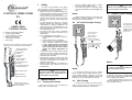
OPERATING
INSTRUCTIONS
P-1 indicator functionality includes:
• AC/DC voltage indication,
• Unipolar indication of phase,
• Circuit continuity check,
• Phase rotation indication,
• RCD testing.
L1
Probe L2
+
L2
LED illuminating the
measurement point
690
400
230
120
Unipol phase
indicator
LED voltage
indicator
RL
50
24
12
V
Arrows indicating
phase rotation
Continuity indicatori
(R<400kΩ)
DC voltage polarization
indicator (L2 probe)
•
Test the voltage indicator using a voltage
source with known voltage value,
Short circuit the probes – an audible signal
should be generated and LED Ω
should
be lit.
Touch electrode
Note:
The device can be used in rainy conditions,
however at user’s own responsibility. It is
recommended to use gauntlets.
Illumination switch
2
Measurement electrode
protector (placed on blades
of both diameters)
2.1
Measurements
Testing of the device
Every time you want to use the device you
need to check if it works properly:
Note:
Between the last measurement and the test
you need a break of at least 240s.
2.4
Notes:
Unipolar Phase Testing
Voltage indication function is active also with
discharged or removed batteries. All remaining
functions require charged batteries.
2.2
AC and DC Voltage Testing
Connect probe L2
to the tested object.
Press the touch electrode.
+
L2
690
400
230
120
Connect both probes
to the live object.
RL
LED being turned on
indicates presence of
voltage > 50V.
50
24
12
V
+
L2
L1
Voltage is shown on
the LED indicator.
690
400
230
120
AC voltage is indicated
by LED
being turned on.
RL
50
24
12
V
For DC voltage, when probe
L2 is connected to source’s
“+”, LED is turned od,
otherwise LED is turned
on.
Notes:
Notes:
AC voltage indicator
P-1
Probe L1
Electrodes of varying diameter. Unscrewing the blade
causes a reduction of the diameter of the electrode.
To ensure correct utilization of the device
and correctness of obtained results the following
recommendations have to be adhered to:
• Before you start to use the device read this instruction carefully and follow OHS standards
and manufacturer’s recommendations.
• Using the device for purposes other than described in this instruction can result in a damage or can be a source of a serious hazard for
the user.
• The device should be used only by persons
suitably qualified and licenced to perform
measurements in electrical installations. The
device when used by unqualified persons, can
become damaged or can be a source of a serious hazard for the user.
• The device must not be used in dangerous
environments e.g. where an explosion or fire
hazards exist.
• It is unacceptable to use the device if:
⇒ It is damaged and is partially or totally unusable,
⇒ Its test lead’s insulation is damaged,
⇒ It was stored for a prolonged period of
time in unsuitable conditions (e.g. in high
humidity). After the device is moved from
a cold to warm environment, do not perform any measurements until the device
reaches the ambient temperature (ca
30min).
• You must not use the device while the battery
compartment is fully or partially open and you
must not use a power supply unit other than
described in this instruction.
• Measurements should not last longer than
30s. After a measurement that takes 30s, the
subsequent measurement can be taken not
earlier than after 240s.
• Bounding values indication is intended as a
warning feature and shouldn’t be used for
measurements.
•
P-1
VOLTAGE INDICATOR
P-1
Safety
P-1
1
In networks secured with 10mA or 30mA
RCDs, the RCD may get triggered while measuring the voltage between L and PE. To avoid this
situation connect the device between L and N and
after approx. 5s move the probe from N to PE.
2.3
RCD Testing
In order to test an RCD with nominal current
value of 10mA or 30mA you need to perform a
voltage test between phase L and PE lead.
Note!
You must not touch the electrode of L1 test
probe during phase testing.
During unipolar phase testing the results can
be incorrect if the user is too well insulated from
the ground (e.g. while using insulated safety clothing or insulated work platform).
Unipolar phase testing can be an insufficient
method to determine if the circuit is live. You need
to use a bipolar method.
Circuit Continuity Test
Note!
The tested circuit may be live.
Connect both probes to the tested circuit. An
audible signal and activated LED Ω
indicates
that the circuit is continuous (R<400kΩ).
Note:
Voltage polarization on L2 probe is positive.
2.6
Phase Sequence Test
L1
L1
L3
N
Illumination of Measurement
Point
P-1 can provide illumination of the area
around the point being measured. This is important in locations with poor light (e.g. in distribution
substations). To turn on illumination press the but.
ton marked
3
Battery Replacement
The device is powered from two AAA 1.5V
batteries. Absence of an audible signal after short
circuiting of probes or weak illumination after
pressing the button
is an indication that the
batteries need to be replaced. To do it follow the
procedure below:
Connect probe L1 to
assumed phase L1
and probe L2 to assumed
phase L2. Press the touch
electrode.
L2
PE
2.7
+
L2
The voltage is shown
on the LED indicator.
P-1
2.5
690
400
230
120
LED R turned on
indicates in-phase
rotation.
RL
50
24
12
V
+
OPEN
LED L turned on
indicates out of phase
rotation .
4
CLOSE
Cleaning and Maintenance
P-1
After swapping the probes
the opposite arrow should
turn on.
- Disconnect both probes
from the tested circuit.
- Using a tool or a coin
unscrew the battery container
by a counter clickwise
movement and remove it.
- Replace the battery paying
attention to correct polarization.
- Insert the container rotating
it clockwise.
NOTE!
Use only maintenance methods that the manufacturer specified in this instruction.
The device can be cleaned using a soft, damp
cloth using generally accessible detergents. Do
not use any solvents or cleaning agents that could
scratch device’s housing (polishing powders,
creams etc.).
Notes:
Phase sequence can be tested only in a 3
phase installation.
Electronic circuitry is maintenance free.
5
Storage
When storing the device you need to comply
with the following guidelines:
• Replace protective caps on the probes,
• Make sure that the device is dry,
•
Decommissioned electrical equipment should
be sent to an appropriate waste depot in compliance with legal acts governing electronic waste
management..
s) Frequency range for bipolar phase rotation indicator: 50…60Hz
t) Power supply: 2x1.5V AAA/LR03
u) Dimensions: ok. 240x60x30 mm
v) Weight with batteries: ok. 0,2kg
w) Working temperature: -10..+55°C
x) Storage temperature: -30°C..+70°C
y) Quality standards: design and manufacturing
ISO 9001 compliant
z) the product meets the EMC requirements
(immunity for industrial environment) according to the following standards EN 613261:2006 and EN 61326-2-2:2006
Do not disassemble the equipment before
sending it to a waste depot.
8
Follow local legislation regulating disposal of
packaging and batteries.
The manufacturer of the device and a provider of warranty and post-warranty services is:
6
If the device is to be stored for a prolonged
period of time, remove the batteries.
Decommissioning and Recycling
Decommissioned electrical equipment should
be stored separately from other type of waste.
7
Technical Specifications
a) Type of insulation: double, EN 61010-1 compliant
b) Safety category: III 1000V (IV 600V) as per
EN 61010-1
c) Housing degree of protection as per EN
60529: IP65
d) Voltage range: 12…690V AC/DC
e) Voltage indications: 12V, 24V, 50V, 120V,
230V, 400V, 690V
f) input resistance
Uin
12V, 24V, 50V
120V
230V
400V
690V
Rin
~ 6kΩ
~ 20kΩ
~ 70kΩ
~ 150kΩ
~ 240kΩ
g) Accuracy of voltage indications: as per EN
61243-3
h) Voltage frequency range: 0…400Hz
i) Maximum current: IS<0,2A/IS(5s)<3,5mA
j) Maximum work interval: 30s
k) Minimum recovery time after being connected
for 30s: 240s
l) Minimum voltage triggering the device: <12V
m) Voltage range for unipolar phase indicator:
50…690V
n) Frequency range for unipolar phase indicator:
50…400Hz
o) Continuity test range: 0…400kΩ
p) Continuity test accuracy: ±50%
q) Continuity test current: 3µA
r) Voltage range for bipolar phase rotation indicator: 100…690V
Manufacturer
SONEL S. A.
ul. Wokulskiego 11
58-100 Świdnica
tel. (0-74) 858 38 60
(0-74) 858 38 00
fax (0-74) 858 38 08
e-mail: [email protected]
internet: www.sonel.pl
Note:
The manufacturer is the only service provider
authorized to provide repair the device.
Note:
The manufacturer reserves the right to introduce changes to device’s look, accessories
and specifications.
Version 1.7 23.02.2011