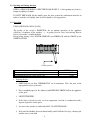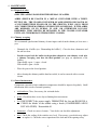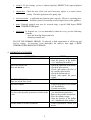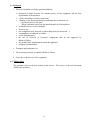
1
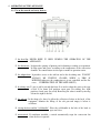
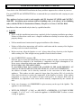
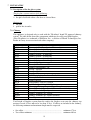
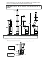
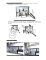
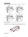
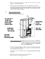
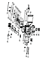
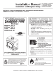
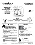
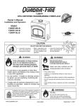
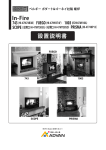
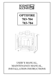
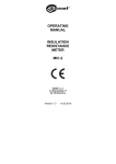
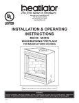
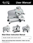
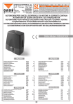
OPTIFIRE
780 USA/CN
USER'S MANUAL,
MAINTENANCE MANUAL,
INSTALLATION INSTRUCTIONS
Dear Customer,
Congratulations on the purchase of your new Bodart & Gonay appliance!
Your choice shows the recognition you have for high quality products. You are now a member of the
large international family of Bodart & Gonay customers, who have enjoyed for many years the
elegance, efficiency and reliability of our equipment.
This is why we deem it important to provide you with this user's and maintenance manual: to allow
you to use your equipment under the best possible conditions and in the most optimal manner, and
furthermore to increase its operating life. We strongly advise you to read it carefully.
And, of course, to store it in a place where you are sure to find it again without any problem.
Please record in the space below the date of purchase, reference and the name and address of your
supplier, so that this information is always kept safely.
Also keep carefully the invoice or proof of purchase (necessary for the warranty). We advise you to
clip them together with this manual.
We wish you every satisfaction with your Bodart & Gonay equipment.
Type of equipment: ......................................................................................................................
Reference: ....................................................................................................................................
Date of purchase: ……/……/……
Dealer:
name: ............................................................................................................................................
street: ............................................................................................................................................
city: ..............................................................................................................................................
phone: ..........................................................................................................................................
2
TABLE OF CONTENTS
USERS AND MAINTENANCE MANUAL
1.
Important recommendations ______________________________________________ 4
2.
Operation of the appliance _______________________________________________ 5
2.1. Use of the control and safety devices __________________________________________ 5
2.2. Opening and closing the door ________________________________________________ 6
2.3. Operation ________________________________________________________________ 6
3.
Maintenance __________________________________________________________ 8
3.1. Disposal of ashes ___________________________________________________________ 8
3.2. Chimney sweeping _________________________________________________________ 8
3.3. General maintenance _______________________________________________________ 8
4.
Operation anomalies ____________________________________________________ 9
5.
Guarantee____________________________________________________________ 10
5.1. Duration and limitation ____________________________________________________ 10
5.2. Reservation ______________________________________________________________ 10
5.3. Exclusion ________________________________________________________________ 11
5.4. Taking effect _____________________________________________________________ 11
INSTALLATION INSTRUCTIONS
6.
Safety _______________________________________________________________ 12
7.
Installation ___________________________________________________________ 13
7.1. Description of the fire place system __________________________________________ 13
7.2. Chimney ________________________________________________________________ 13
7.3. Minimum clearance to combustible __________________________________________ 14
7.4. Connection of hot air ducts_________________________________________________ 15
7.5. Natural convection (no fan installed) _________________________________________ 15
7.6. Forced convection (fan kit option) Reference: 37B78047 _________________________ 16
7.7. Adjustment of the baffles___________________________________________________ 19
7.8. Dismantling the baffles ____________________________________________________ 20
7.9. Framing dimensions. ______________________________________________________ 21
7.10.
Installation of appliance _________________________________________________ 21
7.11. Fireplace framing and facing _______________________________________________ 23
8.
Spare parts description _________________________________________________ 24
3
USERS AND MAINTENANCE MANUAL
1. IMPORTANT RECOMMENDATIONS
•
Carry out the installation and follow the safety rules (refer to Installation instructions).
•
Never leave children unattended when there is a fire burning in the fireplace.
•
THE FIREPLACE MUST BE OPERATED WITH THE DOORS FULLY CLOSED.
•
KEEP COMBUSTIBLE MATERIALS AT LEAST 48 INCHES AWAY FROM THE
FRONT OF THE FIREPLACE OPENING.
•
DO NOT USE PRODUCTS THAT ARE NOT SPECIFIED FOR USE WITH THIS
FIREPLACE
•
DO NOT ELEVATE FIRE, OR USE GRATE. BUILD WOOD FIRE DIRECTLY ON
HEARTH
•
OPERATE ONLY WITH DOOR CLOSED
•
USE SOLID WOOD FUEL ONLY
•
First fire
The first fire bakes the paint which results in an emission of smoke.
VENTILATE THE ROOM
DO NOT TOUCH THE PAINT UNTIL THE APPLIANCE HAS COOLED,
BECAUSE IT GETS SOFT AT THE FIRST FIRING.
•
It is mandatory at each fire
- TO SHUT THE DOOR OF THE ASH BOX;
- TO CLOSE THE DOOR FLAP;
4
2. OPERATION OF THE APPLIANCE
2.1. Use of the control and safety devices
the door flap: NEVER KEEP IT OPEN DURING THE OPERATION OF THE
APPLIANCE.
the thermostat: It adjusts the quantity of primary air for burning according to its position.
Its flap opens and closes according to the temperature of the convection
chamber. Its control button is telescopic to make its operation easier.
the ashpan door: It provides access to the ash box and to the de-ashing arm. IT MUST
ALWAYS BE TIGHTLY CLOSED WHEN A FIRE IS
BURNING(otherwise the combustion air is not controlled and the fire
races OVERHEATING OF THE APPLIANCE).
de-ashing arm: To use it, pull it towards the front. It is used to adapt the grate to the type
of fuel to be burnt (left position: open grate for starting fire; right
position: closed grate for wood). Removing the ashes is made by moving
it from the right to the left.
the ash pan: In the shape of a shovel to allow the collection of ashes at the back of the
equipment. Monitor the filling of the ash pan and empty it before it
overflows.
closing the door and the "cold handle": Place the cold handle in the hole of the latch to
open and close.
microswitch: If ventilation installed, a switch automatically stops the convection fan
when the door is opened.
5
2.2. Opening and closing the door
WHEN A FIRE IS BURNING, OPEN THE DOOR SLOWLY. A fast opening may lead to a
temporary spillage of smoke.
TO SHUT THE DOOR, lift the handle, press the door against the combustion cham-ber in
order to crush the seal slightly, then lower the handle to its stop position.
2.3. Operation
USE SOLID WOOD ONLY (LOGS)
The quality of the wood is ESSENTIAL for an optimal operation of the appliance
(efficiency, cleanliness of the window, ...). A quality wood is a dry wood having dried at
least 2 years under a ventilated shelter.
Except when starting a fire, NEVER OPERATE your FIRELACE with the GRATE in the
OPEN POSITION.
Closed position
Model
Maximum load (for low rate burning only)
Recommended load for 1 hour at max. rate
•
OPTI 780
24 lbs
10 lbs
Lighting the fire
1
OPEN fully the air flow: THERMOSTAT set on maximum. Place the grate in the
open position (lever to the left).
2
Place crumpled paper (or fire lighters) and KINDLING FIREWOOD in the appliance
on the grate.
3
LIGHT THE FIRE.
4
If the door is closed too early, too low temperature can lead to condensation and a
deposit of particles on the glass.
5
As soon as the window is sufficiently HOT, CLOSE THE DOOR.
6
Wait until the kindling firewood burns briskly and LOAD the first logs, choosing the
smaller ones to start with.
6
•
7
START the heat circulation FAN (if installed).
8
When the fire is brisk and the unit is hot, CLOSE THE GRATE (lever to the right),
adjust the thermostat to the position wanted.
9
When using a fan, ADJUST THE SPEED OF THE FAN to obtain the quantity of hot
air that you need.
Long duration combustion
- Keep a bed of glowing embers of 1 to 2 inches on the bottom of the appliance;
- Choose logs that are thick
- Position the thermostat in accordance with the draft of your chimney. A reduced rate
is generally obtained from 0 to 3.
Remark:
AVOID OPERATING AT A REDUCED RATE WHEN ATMOSPHERIC
CONDITIONS ARE UNFAVOURABLE (low pressure and high humidity) as this could
cause problems.
Creososte – Formation and Need for Removal:
When wood is burned slowly, it produces tar and other organic vapors, which combine
with expelled moisture to form creosote. The creosote vapors condense in the relatively
cool chimney flue of a slow-burning fire. As a result, creosote residue accumulates on
the flue lining. When ignited this creosote makes an extremely hot fire.
The chimney should be inspected at least twice a year during the heating season to
determine when a creosote buildup has occurred.
When creosote has accumulated it needs to be removed to reduce the risk of a chimney
fire.
•
Prohibited fuels
The use of treated wood (painted, ... etc.) and any other salvaged material that can emit
noxious gazes for the environment and is corrosive towards the components of the
appliance is NOT ALLOWED and eliminates the rights of guarantee. For the same
reasons, PETROLEUM COKE must not be used.
NEVER USE GASOLINE, GASOLINE-TYPE LANTERN FUEL, KEROSENE, CHARCOAL
LIGHTER FLUID, OR SIMILAR LIQUIDS TO START OR ‘FRESHEN-UP’ A FIRE IN THIS
FIREPLACE. KEEP ALL SUCH LIQUIDS WELL AWAY FROM FIREPLACE WHEN IT IS IN USE.
7
3. MAINTENANCE
3.1. Disposal of ashes
OPEN THE ASHPAN DOOR FOR THE DISPOSAL OF ASHES.
ASHES SHOULD BE PLACED IN A METAL CONTAINER WITH A TIGHTFITTING LID. THE CLOSED CONTAINER OF ASHS SHOULD BE PLACED ON
A NONCOMBUSTIBLE FLOOR OR ON THE GROUND, WELL AWAY FROM
ALL COMBUSTIBLE MATERIALS, PENDING FINAL DISPOSAL. IF THE ASHES
ARE DISPOSED OF BY BURIAL IN SOIL OR OTHERWISE LOCALLY
DISPERSED, THEY SHOULD BE RETAINED IN THE CLOSED CONTAINER
UNTIL ALL CINDERS HAVE THOROUGHLY COOLED.
3.2. Chimney sweeping
We recommend a professional chimney cleaner inspect and clean the chimney at least once a
year.
-
Dismantle the 2 baffles (see “Dismantling the baffles”). Close the door, thermostat and
the ash box door.
-
In order to put back the baffles in the position adapted to your chimney stack after
a chimney sweeping, note here the ideal position (see page on adjustment of the
baffles):
Upper baffle: open - ½ open – closed
Lower baffle: open - closed
-
Place the grate in the closed position .
-
After cleaning the chimney and the dust has settled, it can be removed with a vacuum
cleaner.
3.3. General maintenance
Components exposed to high combustion temperatures should be inspected regularly. Small
deformation does not alter a normal operating.
•
air distributor: Clear, if necessary, the air intake holes.
•
grates: Check that there are no objects limiting their movements.
•
fan: DISCONNECT the power supply, DISMANTLE the fan and RE-MOVE it.
CLEAN the blades of the turbine using a brush (COM-PRESSED AIR IS
NOT ALLOWED). Reassemble all.
•
thermostat: Check its correct clearance. Your dealer can check the adjustment.
•
door: Check the sealing of the stainless steel seal. If necessary, your dealer may adjust
or replace it. Check the correct operation of the lock and of the opening safety.
8
•
window: If, for cleaning, you use a chemical product, PROTECT the exposed painted
surfaces.
•
ashpan door: Check the state of the seal and if necessary replace it to ensure correct
sealing. Check the operation of the spring clip.
•
refractory bricks: A spilt brick may function quite correctly. However, a missing piece
should be replaced to maintain an efficient protection of the appliance.
•
paint: Damaged painted areas may be restored using a special 1200 degree HIGH
TEMPERATURE paint.
•
lubrication: In frequent use, it is recommended to lubricate every year the following
elements:
- door and door flap: hinges and lock;
- thermostat control axis.
DO NOT USE NORMAL GREASE. If subjected to high temperatures it will dry up and
lead to seizing. If necessary, clean thoroughly the surfaces, then apply a HIGH
TEMPERATURES RESISTANT GREASE .
4. OPERATION ANOMALIES
ANOMALIES
THE WINDOW GETS DIRTY TOO QUICKLY
VENTILATION FAN
Does not function
-
VENTILATION FAN
Operates but the flow is low
Excessive DRAFT
-
CURES
Check the moisture of the fuel;
Open the passage of the baffles
( see "Adjusting the baffles").
Check the operation of the motor;
Check the microswitch;
Check (and replace) the fuse of
the variable speed switch;
Check the thermocontact;
Check (and repair) the power
supply.
Clean the blades of the turbines.
- Tighten the passage of the baffles
(see Installation);
- Consult your dealer.
DRAFT
- Check
the
chimney
Too low with a possible generation of smoke in the
(see installation instructions);
room
- Remove the possible obstruction;
- Have the chimney swept;
- Open the passage of the baffles
(see "Adjustment of the baffles").
Trouble linked to weather conditions
- If this is permanent, consult your
dealer.
9
THE FIRE IS NOT BRISK ENOUGH
-
THE THERMOSTAT DOES NOT CLOSE
ANYMORE:
- A foreign body prevents the closing of the flap
- Mechanical blocking
THE THERMOSTAT REMAINS CLOSED:
1 When COLD, the flap only rises from mean dial
positions
2 When COLD, the flap does not rise
THE FIRE CANNOT BE CONTROLLED:
- The DOOR of the ash box is open or unsealed
- The DOOR of the appliance is not sealed
Check the moisture of the fuel;
Check the thermostat;
Empty the ash box;
Clear the holes of the distributor.
- Remove the foreign body
- Replace the thermostat
- Calibrate the adjustment
- Replace
the
thermostat
(thermostat bulb destroyed by
overheating)
- Check the correct closing of the
ash box door;
- Check the seal, replace if
necessary;
- Adjust again the door seal;
- Adjust again the position of the
closing roller.
In case of a chimney fire, immediately close the door, the ash box door and the thermostat .
5. GUARANTEE
5.1. Duration and limitation
•
•
•
•
6 years guarantee on: the general structure;
2 years guarantee on: the inner removable parts;
1 year guarantee on: grates, thermostat, fan and variable speed control switch;
no guarantee on: window, seals, bricks and cast iron plates.
5.2. Reservation
Bodart & Gonay reserve the right to modify their equipment, catalogues and manuals
independently, at any time and without prior notice.
The validity of the guarantee is cancelled in case the mandatory recommendations of this
manual are not fulfilled.
The interventions under the guarantee are only made through the dealer on presentation of
the purchase invoice.
Parts will be delivered only against the faulty parts.
10
5.3. Exclusion
1 Disasters, breakdown or faulty operation linked to:
•
•
•
•
•
•
•
•
•
•
•
inadequate relation between the nominal power of the equipment and the heat
requirements of the premises;
a faulty installation or faulty connections;
a damage to the thermostat through overheating due to intensive use:
- the ash box door is left open;
- When ventilation convection fan installed and left off at high fires.
an insufficient or excessive draught;
incorrect use;
non compatible fuels, destructive and/or damp fuels (treated wood, ...);
consumption exceeding the use limits;
a lack of maintenance;
the use of electrical or electronic components that are not approved by
Bodart & Gonay;
any modification, transformation inside the appliance;
transport and installation.
2 Transport and packaging cost.
3 All costs not previously accepted by Bodart & Gonay.
4 Costs due to the non-use of the equipment.
5.4. Taking effect
The guarantee starts on the date written on the invoice. The invoice is the only document
valid for the guarantee.
11
INSTALLATION INSTRUCTIONS
Your dealer is the SPECIALIST that Bodart & Gonay and their importers have chosen in your area.
For your SAFETY and SATISFACTION we recommend that you entrust him with carrying out your
installation.
This appliance has been tested to and complies with UL Standard 127 (05/99) and CAN/ULCS610-M87. Installation must conform with local building codes, or in absence of local building
codes, with the NFPA 211 Standard for Chimney, Fireplaces, & Vents, CAN/CSA B365.
Installation of this unit should only be done by a qualified installer.
6. SAFETY
•
Please read this installation instructions completely before beginning installation procedures.
Failure to follow them could cause a fireplace malfunction resulting in serious injury and/or
property damage.
•
Follow manufacturer's instructions for proper installation of the chimney.
•
Failure to follow these instructions will void the certification and the warranty of the fireplace
and may result in an unsafe installation.
•
Before servicing, allow the fireplace to cool. Always shut off any electricity to the fireplace
while working on it. This will prevent any possible electrical shock or burns.
•
Any COMBUSTION consumes AIR.
From the gap at an entry door threshold to the direct outside air intake, everyone must choose
the solution best adapted to the installation to compensate the slight consumption of air.
Never create a depression in the room where the appliance is installed.
DO NOT SEAL ALL THE AIR INTAKES.
IF AN EXTRACTION FAN CANNOT BE AVOIDED IN THE SAME PREMISES, AN
ADEQUATE AIR INTAKE MUST BE PROVIDED TO AVOID ANY DEPRESSION.
An outdoor air intake can be directly connected to the convection air inlet under the
appliance. This outdoor air inlet cannot be bigger than 32sq inches (50% of air inlet for
convection) in order not to reduce the temperature of the fireplace too much. If the outdoor
temperature is very low, the outdoor air inlet could need to be reduced. With such an
installation, any depression in the room will be naturally compensated by the external air
inlet.
•
In the case of masonry, it is FORBIDDEN to place masonry on the top of the Optifire. The
appliance is not load bearing.
•
WITH OR WITHOUT A FAN, an AIR INLET of MINIMUM 65 SQUARE INCHES
(example: 2" x 32.5" or 6" x 12") under the appliance is MANDATORY to allow a correct
cooling of appliance.
12
7. INSTALLATION
7.1. Description of the fire place system
The fire place system consists of the following:
1 chimney system;
2 fire place itself with either a flat door or a bowed door.
Options are:
1 fan unit;
2 grid for hot air outlet.
7.2. Chimney
This appliance is designed only to work with the "Heatilator" brand UL approved chimney
system. The table below shows the components which may be safely used with fireplace.
(Note: Heatilator is a trademark of Heatilator, Inc., a division of Hearth Technologies, Inc.
Bodart & Gonay is not associated with either company.)
Catalog #
CAK4
SL306
SL312
SL318
SL324
SL336
SL348
SL3
SL315
SL330
FS338
FS339
FS340
AS8
JB877
CB876
RF370
RF371
TR342
TR344
ST375
TS345
TS345P
CT35
Description
Chimney Air Kit (Canadian installation only)
Chimney Section – 6 inch long
Chimney Section – 12 inch long
Chimney Section – 18 inch long
Chimney Section – 24 inch long
Chimney Section – 36 inch long
Chimney Section – 48 inch long
Chimney Stabilizer
Chimney Offset/Return – 15°
Chimney Offset/Return – 30°
Firestop – Straight
Firestop – 15°
Firestop – 30°
SL300 Straight Attic Insulation Shield, 24°
Chimney Joint Band
Chimney Bracket
Roof Flashing – Flat to 6/12 Pitch
Roof Flashing – 6/12 to 12/12 Pitch
Telescoping Chimney Terminal Cap – Round
Chimney Terminal Cap – Round (Storm collar included)
Chimney Terminal Cap – Square
Chimney Terminal Cap – Square
Chimney Terminal Cap – Square (Painted)
Chase Top
Total height of fireplace system from the surface the fireplace rests onto the chimney top
must not exceed 25 feet and not be less than 15 feet. If offsets are included in the chimney,
the following minimum and maximum length must be respected.
• One offset: ................................................................................... minimum 17 feet
• Two offsets minimum: ................................................................ minimum 20 feet
13
Chimney must extend at least 3 feet (915 mm) above its point of contact with the roof and at
least 2 feet (610 mm) higher than any roof or wall within 10 feet (3 m) .
YOU
MUST HAVE A TWO INCHES CLEARANCE BETWEEN THE CHIMNEY AND ANY
DO NOT FILL THIS SPACE WITH INSULATION OR ANY
COMBUSTIBLE MATERIALS.
MATERIAL.
Max. 25 Feet
YOU MUST CONFORM WITH ALL RECOMMENDATIONS FROM "HEATILATOR" FOR USE AND
INSTALLATION OF THEIR CHIMNEY SYSTEMS.
7.3. Minimum clearance to combustible
All minimum clearances to combustible are determined by small stand offs:
2’’clearance
to back
1 ‘’ clearance
to sides
14
7.4. Connection of hot air ducts
•
If a COMBUSTIBLE MANTLE is installed, ONE FRONT AIR DUCT MINIMUM must
be connected (with or without a fan).
•
Hot air ducts must be Aluminum 5" flex pipe wrapped with rockwool , ceramic blanket
or any 250°C resistant insulation.
•
Vent grills must be part (ref: 37B78043).
•
AIR VENT GRILLS must be centered NOT LESS THAN 28 INCHES ABOVE THE
TOP OPENING OF THE FIREPLACE AND NOT LESS THAN 15 INCHES BELOW
THE CEILING.
•
An AIR INLET OF MINIMUM 65 SQUARE INCHES (example: 2" x 32.5 ") under the
appliance is MANDATORY to allow a correct cooling of appliance.
7.5. Natural convection (no fan installed)
UL tests require at least 1 air duct to be installed and insulated if a combustible mantle is
placed .
However, Bodart & Gonay advises to install 2 air ducts (one on each side) if no fan is
installed. This will cool down the appliance more efficiently and will give more hot air
circulation .
15
7.6. Forced convection (fan kit option) Reference: 37B78047
Electrical connection: 115 V~ 60 Hz 0,72 A 85 W
THIS APPLIANCE WHEN INSTALLED, MUST BE ELECTRICALLY GROUNDED
IN ACCORDANCE WITH LOCAL CODES, WITH THE NATIONAL ELECTRICAL
CODE, ANSI/NFPA 70-1990, OR THE CANADIAN ELECTRICAL CODE, CSA
C2.2.1.
To install the fans, we advise you to take off the frame and the door.
The fan installs through the inside. Take off the 2 fire grates and their stainless steel
blocking parts in front of them, the bricks behind and on the sides and the grates support.
Unscrew the 6 screws from the ash-pan’s box.
Take off the ash-pan and then the box through the ash-pan door.
Connection to the electrical circuit is:
•
•
•
green / yellow ..........................................................................................
ground
blue .......................................................................................................... common
brown .......................................................................................................
line
You can make the electrical connection. The fan wires need to pass through the dedicated
hole on the left side of ash box (photo 4). Then you can place the switch support on the
appliance and screw it (photo 5).
16
Photo 4
photo 5
Connect with the fan. Place fan in the insert (be careful with orientation !). The fan does not
require any fastener.
•
Important remark
To maintain good air tightness adjust the ventilation cap with the front ash pan box.
This ventilation cap must be removed and placed back when a fan is installed.
17
How to install a thermocontact (optional)
• Screw the thermocontact on the back side from the electrical box (1 nut is fixed).
Be careful Don’t screw the thermocontact too hard.
•
Disconnect a terminal spade tag from one of the doorswitch terminals and connect it to
one of the thermocontact terminals. Connect the remaining cable to the two free
terminals.
Rubber bushing installation.
•
The rubber bushing must be positioned into the round hole on the left of ashpan door.
18
7.7. Adjustment of the baffles
The baffle system is designed to adapt the appliance to the draught of the chimney. The
baffles rest on square supports.
Baffles from the most closed to the most opened position (pictures 1 to 3).
Picture 4: wrong position
The upper baffle has on each side 3 positioning notches, allowing to open or to close the flow
of smoke at the back, as well as release notch for the assembly and dismantling of the baffles.
1
positioning notches
release notch
2
19
The lower baffle may be turned around and thus open the passage for the smoke in the front
(for instance if the equipment back-drafts too easily). It also includes two release notches.
1
2
positioning notch
release notch
The most closed position is the best for the efficiency of the appliance. However, if the
equipment tends to smoke back, open the baffles gradually.
7.8. Dismantling the baffles
1 Place the upper baffle in the release position.
2 Raise slightly the lower baffle and move it to bring the release notch at the height of the
square support.
3 Lift one side and try to lower the other side of the baffle by passing the square support
through the notch.
4 Remove the baffle by tilting it so that it passes through the door outside of the appliance.
5 Raise slightly the upper baffle and move it to bring the release notch at the height of the
square support.
6 Lower one side of the baffle by passing the square support through the notch.
7 Remove the baffle by tilting it so that it passes through the door outside of the appliance.
20
7.9. Framing dimensions.
A minimum depth of 21", width of 33" and height between 39" and 51" (45"minimum with a
fan) is required.
7.10.
Installation of appliance
•
Only if the fireplace rest on a combustible surface, a hearth extension of minimum 16"
must be installed in front of the fireplace. It need to be extended 8” beyond each side
of the opening. It is to protect the combustible floor from both radiant and sparks.
Place the metal hearth strip, supplied with the appliance, approximately 2 inches under
the front edge of the fireplace. It is to protect the gap between the appliance and the
hearth extension.
•
•
Place the unit in the desired location.
Determine the height (telescopic feet). BEWARE! Respect the minimal 2 inches intake
for convection air.
You must introduce (1) and screw (2) the feet. Then you must pin the feet (3). Therefore:
bore a 5,25 mm diameter with the delivered bit and place the auto tapping screws.
•
21
•
•
•
•
Install the appliance in height and LEVEL (side to side and front to back).
Provide a passage of the electrical feeding wire of the motor when making the installation.
Fix the connecting part for external pipe to the appliance with the four screw.
Place the internal flue spigot and push it until jamming. Then shut down the security
flaps.
•
Fit the brickwork: first the back and then the sides.
1
2
3
Brick reference
Dimensions (mm)
07CB315
07CB344
07CB300
300 x 150 x 30
300 x 90 x 30
240 x 120 x 30
•
Check the position of the baffles.
•
We advise to make an operation test framing or before bricking up around the
appliance.
22
7.11.
•
Make a first fire to bake the paint (ventilate the room and do not touch the
appliance). CHECK THE DRAFT.
•
Adjust the position of the baffles, if necessary (cf. Adjustment of the baffles).
Note the ideal position of the baffles for your chimney in the space provided
on the first page of this manual. This will allow you to position them again
correctly after a chimney sweeping.
Fireplace framing and facing
Respect the following safety dimensions:
•
Fireplace framing and facing: Maintain the necessary clearances to combustibles.
Required clearances are one inch on each side and
two inches on the back and are guaranteed by stand
offs (see 7.3 Minimum clearance to combustible
and 7.9 Framing dimensions)
•
Realize the frame of the appliance. (In the conception of the frame, do not forget
to provide the MINIMAL SECTION for the passage of the CONVECTION AIR –
inlet of minimum 65 square inches).
•
If the fireplace rest on a combustible surface, an hearth extension must be added
(see 7.10)
•
•
Fitting the trim frame: just slide it into the retainer springs.
Remove the dust on the visible painted surfaces.
23
8. SPARE PARTS DESCRIPTION
Ref
01
02
02
03
03
04
04
04
05
05
06
07
08
09
10
11
12
13
14
15
16
17
18
19
20
21
22
23
24
24
25
26
27
28
29
30
31
33
34
34
35
36
37
38
39
40
41
42
Code
07BP0103
27B78016
27B78017
07RV1039
07RV1041
27B78015
27B78018
37B78021
27660002
27B78022
27660000
37B78014
37B78015
07CB300
07CB315
07CB344
07CB313
07CB336
07CB350
07CB313
07FFIFG
37B78013
37B78012
37B78010
07CB326
07CB327
37B78029
37660016
37B78016
37B78026
37B78006
37B78008
37B78007
27B78014
07PBE001
37B78040
37B78044
07PBB049
27B78027
27B78029
37B78046
37116226
37B77016
37117400
07VM0200
37B78042
37B78038
37B78003
Description
COLD HANDLE IF96+PRISMA
WELDED DOOR OPTI 780 FLAT
WELDED DOOR OPTI 780 ROUND
CERAMIC 656X487X4 OPTI 780
CERAMIC 900 DEV .638 H. 490 EP.
STAINLESS STEEL DOOR SEAL OPTI 780 FLAT
GLASS HOLDER OPTI 780 BOWED
ASSEMBLED DOOR SEAL OPTI 780 BOWED
DOOR LATCH IF 96
DOOR LATCH BOWED OPTI 780
LATCH CATCH IF96
UPPER BAFFLE
LOWER BAFFLE
REFRACTORY BR.240X120X30 VT20
REFRACTORY BRICK 300X150X30
REFRACTORY BRICK 300X90X30
REFRACTORY BR.240X60X30 CHAMFE
REFRACT BRICK CHAMF 90X60X30
CHAMFERED BRICK 180X165X30
REFRACTORY BR.240X60X30 CHAMFE
PAIR OF GRATES IF-GAUMAIS
FRONT GRATE STOP
END CAP BRICK
AIR DISTRIBUTOR
BRICK 150X60X30 CHAMFERED
BRICK 150X60X30 CHAMFERED
LOG RETAINER
LOG RETAINER HOLDER
SPOILER OPTI 780 FLAT
SPOILER OPTI 780 BOWED
GRATES HOLDER OPTI 780
ASHPAN
ASH REMOVAL ARM
ASHPAN PANNEL OPTI 780
ASHPAN DOOR SPRING D950207
ASHPAN DOOR OPTI USA
THERMOSTAT AND PROTECTION OPTI 780 USA
FRAME SPRING
DOOR FRAME 3 FLAT OPTI 780
DOOR FRAME 3 SIDED BOWED OPTI 780
HEARTH STRIP OPTI 780 USA
PROBE MOUNT
STABILIZER SOVEREIGN
HOT AIR PIPE DIA 125
PIPE ADAPTOR DIA 200
ANCHOR PLATE FOR DIA 200 PIPE OPTI 780 USA
TOP SCREEN OPTI 780 USA
PAIR OF FEET 780
Options
Ref
43
44
45
46
47
Code
27B78037
37680048
27B78025
37B78045
37B78048
48
49
37B78043
Description
ELECTRICAL BOX
THERMOCONTACT KIT INFIRE RC93
3-SIDED FRAME FOR FLAT OPTI 780
FAN 450M3 OPTI 780 USA
CABLE ASS OPTI 780 USA
SPED REGULATOR (WITHOUT CABLE)
HOT AIR OUTLET GRID AND BOX OPTI 780 USA
24
Imported by:
Wittus Inc.
PO Box 120
Pound Ridge, NY 10576
USA
T: 914 764 5679
F: 914 764 0465
www.wittus.com