1
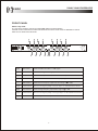
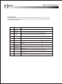
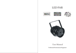
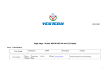
C223
Stereo 2-Way/Mono
3-Way Crossover
USER MANUAL
ED-B3-MA070718-001
CAUTION
RISK OF ELECTRIC SHOCK
DO NOT OPEN
ATTENTION: RISQUE DE CHOC ELECTRIQUE NE PAS OUVRIR
WARNING: TO REDUCE THE RISK OF FIRE OR ELECTRIC
SHOCK DO NOT EXPOSE THIS EQUIPMENT TO RAIN OR MOISTURE
The symbols shown above are internationally accepted symbols that warn of potential hazards
with electrical products. The lightning flash with arrowpoint in an equilateral triangle means that
there are dangerous voltages present within the unit. The exclamation point in an equilateral
triangle indicates that it is necessary for the user to refer to the owner's manual.
These symbols warn that there are no user serviceable parts inside the unit. Do not open the unit.
Do not attempt to service the unit yourself. Refer all servicing to qualified personnel. Opening the
chassis for any reason will void the manufacturer's warranty. Do not get the unit wet. If liquid is
spilled on the unit, shut it off immediately and take it to a dealer for service. Disconnect the unit
during storms to prevent damage.
WARNING
FOR YOUR PROTECTION. PLEASE READ THE FOLLOWING:
WATER AND MOISTURE: Appliance should not be used near water(e.g. near a bathtub, washbowl, kitchen sink, laundry tub,
in a wet basement, or near a swimming pool, etc). Care should be taken so that objects do not fall and liquids are not spilled
into the enclosure through openings.
POWER SOURCES: The appliance should be connected to a power supply only of the type described in the operating
instructions or as marked on the appliance.
GROUNDING OR POLARIZATION: Precautions should be taken so that the grounding or polarization means of an appliance
is not defeated.
POWER CORD PROTECTION: Power supply cords should be routed so that they are not likely to be walked on or pinched
by items placed upon or against them, paying particular attention to cords at plugs, convenience receptacles, and the point
where they exit from the appliance.
SERVICING: To reduce the risk of fire or electric shock, the user should not attempt to service the appliance beyond that
described in the operating instruction. All other servicing should be referred to qualified service personnel.
FOR UNITS EQUIPPED WITH EXTERNALLY ACCESSIBLE FUSE RECEPTACLE: Replace fuse with same type and rating
only.
1
C223
2-WAY, 3-WAY CROSSOVERS
FRONT PANEL
Stereo 2-way mode
In 2-way stereo mode the controls are marked BELOW the horizontal red line.
Channel one and channel two functions are identical in the stereo mode. LEDs are disabled for controls
which are non-functional in this mode.
CHANNEL ONE
240
0
-10
+6
-12
dB
GAIN
INPUT
+12
INPUT
0
960
LOW CUT
Hz
XOVER FREQ
LOW/MID
LOW CUT
LOW/HIGH
9
240
0
-10
dB
GAIN
LOW OUTPUT
x10
-30
INV
LOW OUTPUT
10
0
dB
GAIN
+6
HIGH OUTPUT
11
-6
+6
-12
INV
MONO
STEREO
dB
GAIN
INPUT
12 13 14
680
-30
70
+12
45
40Hz
LOW CUT
15
-10
350
140
680
-30
70
45
40Hz
CHANNEL TWO
-10
350
140
-6
0
960
Hz
XOVER FREQ
MID/HIGH
LOW/HIGH
-30
dB
GAIN
MID OUTPUT
x10
INV
LOW OUTPUT
16
C223
0
Stereo 2-Way/Mono
3-Way Crossover
+6
+6
dB
GAIN
HIGH OUTPUT
INV
HIGH OUTPUT
18
17
[1]&[5]
INPUT GAIN
Controls the INPUT level with +/- 12dB of gain.
[9]&[15]
LOW CUT
Switch for selecting the 40Hz high pass filter. An LED indicates the selection.
[2]&[6]
LOW/HIGH
Selects crossover point between the LOW and HIGH outputs.
[10]&[16] X10 LED
Indicates that the LOW/HIGH crossover frequency range is 450Hz to 9.6kHz.
[3]&[7]
Controls the Low Frequency output level with a range of
LOW OUTPUT
to +6dB.
[11]&[17] PHASE INVERT Switch for reversing the polarity on the low output. An LED indicates the selection.
[4]&[8]
HIGH OUTPUT
Controls the High Frequency output with a range of
to +6dB.
[12]&[18] PHASE INVERT Switch for reversing the polarity on the High Output. An LED indicates the selection.
[14]
STEREO
LED indicating stereo mode operation.
2
C223
2-WAY, 3-WAY CROSSOVERS
Mono 3-Way Mode
In 3-way mono operation the controls are marked ABOVE the horizontal Red line. Front panel controls
not described in this section are not active in mono 3-way mode. LEDs are disabled for controls which
are nonfunctional in this mode.
[1]
INPUT GAIN
Controls the INPUT level with +/- 12dB of gain.
[9]
LOW CUT
Switch for selecting the 40Hz high pass filter. An LED indicates the selection.
[2]
LOW/MID
Selects crossover point between the LOW and MID frequencies.
[10]
X10 LED
Indicates that the LOW/MID crossover range is 450Hz to 9.6kHz.
[6]
MID/HIGH
Selects the crossover point between MID and HIGH frequencies.
[16]
X10 LED
Indicates that the MID/HIGH crossover frequency range is 450Hz to 9.6kHz.
[3]
LOW OUTPUT
Controls the Low Frequency output level with a range of
[11]
PHASE INVERT Switch for reversing the polarity on the low output. An LED indicates that the phase
is reversed.
[7]
MID OUTPUT
Controls the Mid Frequency output Level with a range of
[17]
PHASE INVERT
Switch for reversing the polarity on the Mid Output. An LED indicates that the phase
is reversed.
[8]
HIGH OUTPUT
Controls the HIGH frequency output level with a range of
[18]
PHASE INVERT
Switch for reversing the polarity on the high output. An LED indicates that the phase
is reversed.
[13]
MONO
LED indicating mono mode operation.
3
to +6dB.
to +6dB.
to +6dB.
C223
2-WAY, 3-WAY CROSSOVERS
REAR PANCEL
15WATT
HIGH
CHANNEL TWO
LOW
INPUT
LOW/HIGH
x1
x10
MODE
LF SUM
STEREO
LOW SUM
STEREO
MONO
NORMAL
SUMMED
HIGH
INPUT
LOW/LF SUM
X1
x10
Stereo 2-way/mono
3-way crossover
CAUTION
220V/50Hz
RISK OF ELECTRIC SHOCK
DO NOT OPEN
CHANNEL ONE
C223
LOW/HIGH
ELDER AUDIO FACTORY
HIGH
MID
XOVER FREQ
MID/HIGH
NOT USED
MONO
NOT USED
NOT USED
LOW
XOVER FREQ
LOW/MID
INPUT
For stereo 2-way operation use the markings above the connectors. To
operate the C223 in mono 3-way mode use the markings below the
connectors. The connectors which are not used in the selected mode
are marked "not used". This designation applies only to that mode of
operation.
C223
AUDIO CONNECTIONS
Before connecting anything to the crossover, make sure it is not
connected to any power source. Be sure that the source device(equalizer,
compressor, mixing console, etc.) for the C223 is turned off. Connect
the output(s) of the source device to the inputs of the crossover, following
the rear panel markings carefully. Make sure that the amplifiers which will
be used to drive your speaker system are turned off. Using the back
panel markings as a guide, use high quality cables to connect the
amplifiers to the appropriate outputs of the C223.
ELECTRICAL
CONNECTIONS
Ensure that your C223 crossover conforms to the AC power specifications
in your area, by checking the marked voltage spec on the rear of the unit.
Never plug the incorrect voltage into your crossover, as this may cause
severe damage not covered under the warranty. Connect the power
cord to the crossover first, then to a power source that is properly
grounded. Never lift the ground as a shock hazard may result.
After you have safely plugged in the crossover, turn on the source
device(s). Turn the amplifiers' outputs all the way down(
) and turn
on the amplifiers. All of the elements of your sound system should now
be on, and the amplifiers should be turned all the way down. Turn the
source device to its nominal operating level, sending a nominal(average)
level to the C223 .slowly turn up the amplifiers' outputs until you can
hear signal at a cornfortable volume. Make adjustments as you desire.
FEATURES
X10 OPERATION
If you are using your system in stereo 2-way or 3-way mode, the needed
crossover frequency may be higher than 960Hz, making it necessary
to set the x10 switch to the active position. This changes the range of
operation of the frequency selector from 45-960Hz to 450Hz to 9.6kHz.
All other frequency selectors remain the same. When using the x10
switch, ALWAYS ensure that the amplifiers feeding all speaker systems
are turned off or that the input gain controls on the power amplifiers
are turned down before changing the setting of the x10 switch. Not
doing so may send a spurious signal to the outputs of the crossover
when the x10 switch is engaged, and may damage speaker systems
which are powered at the time of the spurious signal.
POLARITY
SWITCH
Every output is equipped with a polarity( ) reverse switch on the front
panel. When speakers are not "in phase", the frequency response of
the system is compromised, particularly in the low frequencies. Out of
phase signals can also cause comb-filtering" in the high frequencies.
The polarity switch is extremely useful for fine tuning your sound system
for peak performance. An LED is activated when the output polarity is
reversed.
4
C223
2-WAY, 3-WAY CROSSOVERS
The other feature accessed on the back panel is "low frequency summing".
This is useful with systems that utilize mono subwoofers. Activating the LF
sum switch "sums" the low frequencies of both the left and right inputs. The
sum is sent to channel one's low output marked "LF SUM", while channel
two's low output is not used, and channel two's phase invert LED is disabled,
indicating it is not operational in "LF SUM" mode. The summed low frequencies
represent all the low frequencies of both the left and right inputs. And since
lows are generally non-directional anyway ,it will not detract from the true
stereo picture of the source material.
LOW FREQUENCY
SUMMING
You should avoid mounting the unit near large power transformers or
motors. Route the AC cord away from audio lines and plug it into a power
source close by .if the power cord must cross over audio lines, you should
take care to have them cross at 90 degree angles.
RACK MOUNTING,
GROUNDING AND SAFETY
The input and output connectors are balanced/unbalanced XLR TRS-type
connectors. The tip of the plug is wired as hot(+), the ring is wired as cold(-)
and the sleeve is wired as the ground or shield. 1GROUND 2+ 3The C223 crossovers have differentially balanced input and output circuits.
Balanced wiring is recommended, even with unbalanced source devices,
especially when running long paths. Twin-conductor, shielded cable is more
reliable since it does not depend on the shield wire itself to complete the
signal connection. Using twin conductor cable, a broken shield may only
result in a slight increase in noise or hum due to the lack of shielding. You
may also use unbalanced cables to connect to and from the crossover.
If there appears to be no power:
Check that either the stereo or mono LED on the front panel of the C223
is lit.
Check that the power cord is seated properly in the back panel of the
crossover and that it is plugged into an active AC power source.
TROUBLESHOOTING
NO SOUND
If there appears to be power, but no audible signal:
Confirm that active audio lines are connected to the crossover's inputs and
outputs.
Check that both the input and output gain controls are advanced sufficiently.
Check to make sure that you have turned up the amplifiers' outputs.
Ensure that the proper mode for your setup has been selected via the rear
panel mode switches.
Check the LF SUM switch.
Check the X10 switch. This changes the range of the crossover frequency
from 45-1kHz to 450Hz-9.6kHz.
Check that a clean signal is being fed to the crossover.
Confirm that the input wiring is correct.
Check that the grounds of the audio signal path and the chassis and power
line of all units in the system are connected.
5
ABNORMAL AUDIO
OUTPUT
C223
2-WAY, 3-WAY CROSSOVERS
INPUT
Connectors:
Type:
Impedance:
Max input level:
CMRR:
XLR
Electronically balanced/unbalanced, RF filtered
Balanced>50k ,unbalanced>25k
+22dBu typical, balanced or unbalanced
>40dB, typically >55dB at 1kHz
OUTPUT
Connectors:
Type:
Impedance:
Max output level:
XLR
Electronically-balanced/unbalanced, RF filtered
Balanced 200 , unbalanced 30
>+20dBu balanced/unbalanced into 600 Ohm or greater
PERFORMANCE
Bandwidth:
Frequency response:
Signal-to-noise:
Dynamic range:
THD+noise:
Interchannel crosstalk:
20Hz to 20kHz, +0/-0.5dB
<3Hz to >90kHz, +0/-3dB
Ref: +4dBu, 22kHz measurement bandwidth
>106dB, unweighted, any output
<0.004% at +4 dBu, 1kHz
<0.04% at +20 dBu, 1kHz
<-80dB, 20Hz to 20kHz
CROSSOVER FREQUENCIES:
Stereo mode
low/high:
Mono mode
Low/mid:
Mid/high:
Filter type:
45 to 960Hz or 450Hz to 9.6kHz(x10 setting)
45 to 960Hz or 450Hz to 9.6kHz(x10 setting)
45 to 960Hz or 450Hz to 9.6kHz(x10 setting)
Linkwitz-Riley, 24dB/octave,
Function switches:
Front panel
Low cut:
Phase invert:
Rear panel
X10"
Mode:
Lf sum:
Activates 40Hz Butterworth, 12dB/octave High-pass filter, one switch per channel.
Inverts the phase at the output, one switch per output.
Multiplies crossover frequency range by 10, one switch per channel.
Selects stereo/mono and 2/3-way operation.
Selects normal(stereo) or mono-summed low frequency operation.
INDICATORS
Stereo operation:
Mono operation:
Low cut:
X10:
Phase invert:
Green LED
Yellow LED
Red LED per channel
Green LED per channel
Red LED per output(3 peer channel)
POWER SUPPLY
Power consumption:
Mains connection:
220V 10%/50Hz
15WATT
IEC 320 receptacle
PHYSICAL
Dimensions:
Weight:
Shipping weight:
483x175x45mm
1.7kg
2.5kg
Note: specifications subject to change.
6
Beta Three