1
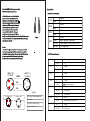
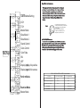
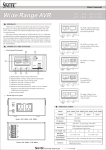
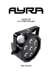
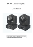
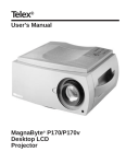
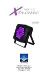
LED PAR
User Manual
Professional Entertainment Equipment
General Instructions:
Please carefully read and understand the instructions in this manual
thoroughly before attempting to operate this unit. These instructions
contain important safety information regarding the use and mainte
nance of this unit. Please keep this manual with the unit, for future
reference.
Main Features:
*Brightness LED
*Produces many Colors, using Green, Purple, Blue, Yellow, & Orange
*DMX -512 Compatible
*Master/Slave Operation
*4/7 DMX Channels
Safety Precautions:
*To reduce the risk of electrical shock or fire, do not expose this unit
rain or moisture
*Do not spill water or other liquids into or on to your unit.
*Be sure that the local power outlet match that of the required voltage for your unit.
*Do not attempt to operate this unit if the power cord has been
frayed or broken.
*Do not attempt to remove or break off the ground prong from the
electrical cord. This prong is used to reduce the risk of electrical
shock and ire in case of an internal short.
*Disconnect from main power before making any type of connection.
*Do not remove the cover under any conditions. There are no user
serviceable parts inside.
*Never operate this unit when it¡s cover is removed.
*Never plug this unit in to a dimmer pack
*Always be sure to mount this unit in an area that will allow proper
ventilation. Allow about 6¡ (15cm) between this device and a wall.
*Do not attempt to operate this unit, if it becomes damaged.
*This unit is intended for indoor use only, use of this product out
doors voids all warranties.
*During long periods of non-use, disconnect the unit¡s main power.
*Always mount this unit in safe and stable matter.
Technical Specifications:
Model NO.:
LED-PAR64-3W-RGB
LEDs :
36*3W LED(R:12 G:12 B:12)
Colors :
RGB
Voltage :
100-250v/50-60Hz
230 (H) x 230(W) x 310(L) mm
Dimensions :
Weight :
5.0Kg
Power Consumption : 120 W
Fuse :
2 Amp GMA
Duty Cycle :
None
DMX :
4/7 Channels
Working Position:
Any safe,secure position
Warranty:
1 year( 365 days)
Cleaning
Due to fog residue, smoke, and dust cleaning the internal and
external optical lenses must be carried out periodically to optimize light output.
1.Use normal glass cleaner and a soft cloth to wipe down the outside casing.
2 .Clean the external optics with glass cleaner and a soft cloth every 20 days.
3 .Always be sure to dry all parts completely before plugging the unit back in.
Cleaning frequency depends on the environment in which the fixture
operates (i.e. smoke, fog residue, dust, dew).
Trouble Shooting
Listed below are a few common problems the user may encounter, with solutions.
Unit not responding to DMX:
Check that the DMX cables are connected properly and are wired correctly (pin 3 is hot; on
some other DMX devices pin 2 may be 'hot'). Also, check that all cables are connected to the
right connectors; it does matter which way the inputs and outputs are connected.
Unit does not respond to sound:
Quiet or high pitched sounds will not activate the unit. If problems are not resolved, contact
your dealer for service.
*Power-supply cords should be routed so that they are not likely to
be walked on or pinched by items placed upon or against them,
paying particular attention to cords at plugs, convenience receptacles, and the point where they exit from the appliance.
*Cleaning -The fixture should be cleaned only as recommended by
the manufacturer. See page 10 for cleaning details.
*Heat -The appliance should be situated away from heat sources
such as radiators, heat registers, stoves, or other appliances (including amplifiers) that produce heat.
*The fixture should be serviced by qualified service personnel when:
A. The power-supply cord or the plug has been damaged.
B. Objects have fallen, or liquid has been spilled into the
C. The appliance has been exposed to rain or water.
D. The appliance does not appear to operate normally or exhibit
marked change in performance.
DMX-512:
DMX is short for Digital Multiplex. This is a universal protocol used as a form of communication between intelligent fixtures
and controllers. A DMX controller sends DMX data instructions from
the controller to the fixture. DMX data is sent as serial data that trav
els from fixture to fixture via the DATA ¡IN¡ and DATA ¡OUT¡ XLR
terminals located on all DMX fixtures (most controllers only have a
DATA ¡OUT¡ terminal).
DMX Linking:
DMX is a language allowing all makes and models of
different manufactures to be linked together and operate from a single
controller, as long as all fixtures and the controller are DMX compliant. To ensure proper DMX data transmission, when using several
DMX fixtures try to use the shortest cable path possible. The order
in which fixtures are connected in a DMX line does not influence the
DMX addressing. For example; a fixture assigned a DMX address of 1
may be placed anywhere in a DMX line, at the beginning, at the end,
or anywhere in the middle. When a fixture is assigned a DMX address
of 1, the DMX controller knows to send DATA assigned to address 1
to that unit, no matter where it is located in the DMX chain.
Data Cable (DMX Cable) Requirements (For
DMX and Master/Slave Operation):
System Menu
DMX 4Channels & Functions
The PAR CAN can be controlled via DMX-512
protocol. It is a 4/7 channel DMX unit. The
DMX address is set below the dome of this PAR
light.Your unit and your DMX controller require
a standard 3-pin XLR connector for data input
and data output (Figure 1). If you are making
your own cables, be sure to use standard two
conductor shielded cable (This cable may be
purchased at almost all pro sound and lighting
stores). Your cables should be made with a male and female XLR connector
on either end of the cable. Also remember that DMX cable must be daisy
chained and can not be split
0
1-255
0
2CH
1-255
0
3CH
1-255
0-7
8-200
4CH
201-247
248-255
1CH
Figure1
.
Notice:
Be sure to follow figures two and three when making your own cables.
Do not use the ground lug on the XLR connector. Do not connect the
cable¡s shield conductor to the ground plug or allow the shield conductor
to come in contact with the XLR¡s outer casing. Grounding
the shield could cause a short circuit and erratic behavior.
1CH
1
3
4CH
1
DMX +
2
3CH
DMX512 I N
3- PI N XLR
COMMON
3
0
5CH
Closed
1-255
R
0
Closed
1-255
G
0
Closed
1-255
B
0
Closed
1-255
2
DMX -
Strobe effect is from slow to fast
Full brightness
DMX 7 Channels&Functions:
2CH
DMX512 OUT
3- PI N XLR
Closed
R
Closed
G
Closed
B
Closed
Adjust general brightness
AdDjust general brightness
0-9
Full brightness
10-248
Color change
Figure2
XLR Male Socket
1Ground
2Cold
XLR Male Socket
2Cold
1Ground
XLR Pin Configuration
pin1=Ground
pin2=Data Compliment(negative)
3Hot
3Hot
6CH
pin3=Data true(positive)
7CH
249-255
Full brightness
0-9
Closed
10-255
Strobe effect is from slow to fast
0-127
Closed
128-255
Sound control
Special Note: Line Termination:
DMX Addrss Setting
4 CH
7 CH
Master Mode
MENU
Slave Mode 1
Slave Mode 2.
Sound-Control
Color-Control
Color Fade
ON
OFF
Displayingdisp, it is positive
Displayingpsid, it is reverse
When longer runs of cable are used, you may need to use a terminator
on the last unit to avoid erratic behavior. A terminator is a 90-120 ohm
1/4 watt resistor which is connected between pins 2 and 3 of a male
XLR connector (DATA + and DATA -). This unit is inserted in the female
XLR connector of the last unit in your daisy chain to terminate the line.
Using a cable terminator will decrease the possibilities of erratic
behavior.
Figure4
1
3
2
Terminationreducessignalerrors and
avoids signaltransmission problemsand
interference.lt is always advisadleto
connect a DMX
terminal,(Resistance120Ohm
1/4W)between PIN2(DMX-)and
PIN3(DMX+)of the last fixture .
5-Pin XLR DMX Connectors:
Some manufactures use 5-pin XLR connectors for DATA transmission in
place of 3-pin. 5-pin XLR fixtures may be implemented in a 3-pin XLR DMX
line. When inserting standard 5-pin XLR connectors in to a 3-pin line a
cable adaptor must be used, these adaptors are readily available at most
electric stores. The chart below details a proper cable conversion.
3-Pin XLR to 5-Pin XLR Conversion
Perform Mode.
Examine Mode
Master Mode
Conductor
Ground/Shield
3-Pin XLR Female(Out
)
5-Pin XLR Male(ln)
Pin 1
Pin 1
data COmpliment(-signal)
Pin 2
Pin 2
Data True(+signal)
Pin 3
Pin3
Not Used
Do Not Use
Not Used
Do Not Use
On-Board System Menu.:
This par can comes with an easy to navigate system menu.
This next section will detail the functions of each command in the
system menu. Please read the next section thoroughly!
To access the main menu press the MENU button. Tap the UP or DOWN
buttons until you reach function you wish to change. When you reach
the function you wish to change press the ENTER button When a function is selected use the UP or DOWN buttons to change the function
settings. Once your changes are made press the ENTER button to
confirm. If the unit remains static for more then eight seconds the fixture
will automatically return to its last setting. To exit without making any
changes press the MENU button.
Addr-DMX Address Setting via control board
1. Tap the MENU button until¡Addr¡ is displayed, press ENTER.
2. ¡X¡ will now be displayed, ¡X¡ represents the displayed address.
Press the UP or DOWN buttons to find your desired address.
3. Press ENTER to confirm, and then press and hold the MENU button
for at least three seconds to assign.
Shnd --Tap MENU button until SHND is displayed, press ENTER. SOUN,
COLO,FADE will be available to choose.
1.Press ENTER for SOUN, this is for sound control mode.
2.Press ENTER for COLO, this is for manual color mode. There are 7
colors for your choose.
3.Press ENTER for FADE, this is for manual color-shade mode. There are
8 speeds for your choose.
CHnd-Channel Changed
1. Tap the MENU button until ¡CHnd ¡ is displayed, press ENTER.
Tap the UP or DOWN buttons until your desired setting is displayed,
press ENTER to confirm.
Shnd -This will let you set unit as a master or slave
in a master/slave configuration.
1. Tap the MENU button until ¡SLnd¡ is displayed, press
ENTER. Either ¡NASe¡¡SL 2¡¡SL 1¡
2. Tap the UP or DOWN buttons until your desired setting is displayed,
press ENTER to confirm.
LED- This will turn the LED on or off
1. Tap the MENU button until ¡LED¡ is displayed, press ENTER.
2. Either ¡ON¡ or ¡OFF¡will now be displayed. Press the UP or
DOWN buttons to select one or the other.
3. Press ENTER, and then press and hold the MENU button for at
least three seconds to confirm.
DISP - This will ¡lip¡ the LED display
1. Tap the MENU button until ¡DISP¡ is displayed, press ENTER.
2. Either ¡OFF¡ (no LED inversion) or ¡ON¡ (LED inversion) will
now be displayed. Press the UP or DOWN buttons to select one or
the other
baLa--Tap MENU button until BALA is displayed, press ENTER. RED,
GREE,BLUE are available to choose.
1.Press ENTER for RED this is for Red color mode.There is for color
adjustment from 0 to 255.
2.Press ENTER for GREE , this is for Green color mode. There is for color
adjustment from 0 to 255.
3.Press ENTER for BLUE this is for Blue color mode.There is for color
adjustment from 0 to 255.
4.Tap MENU button until BALA is displayed, press ENTER. This is for white
color control mode
test-Tap MENU button until TEST is displayed ,press ENTER. This is
for seven colors auto-operation.
Caution!
Tap MENU button for three seconds to enter your
selective Menu mode after you have chosed
MENU Mode press ENTER..