1
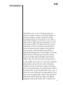
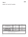
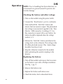
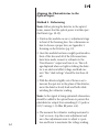
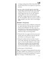
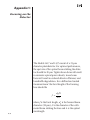
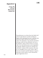
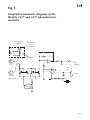
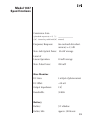
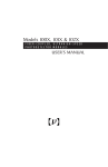
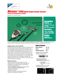
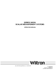
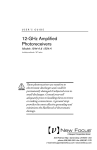
Models 1417 and 1437
User’s Manual
High-Speed
Photodetector Modules
Handling
Precautions
The detector is sensitive to electrostatic discharges
and could be permanently damaged if subjected
even to small discharges. Prior to handling the
detector or making connections, be sure to
ground yourself adequately. A ground strap provides the most effective grounding and minimizes
the likelihood of electrostatic damage.
141702 Rev. B
2
Is a registered trademark of
New Focus, Inc.
Warranty
New Focus, Inc. guarantees its products to be
free of defects for one year from the date of shipment. This is in lieu of all other guarantees,
expressed or implied, and does not cover incidental or consequential loss.
3
4
Contents Handling Precautions
2
Warranty
3
Introduction
5
Operation
8
Appendix 1: Focusing on the Detector
12
Appendix 2: Using the Correct
Microwave Connector
14
Appendix 3: Inside the Photodetector
Module
16
Specifications
18
References
20
Introduction
The Models 1417 and 1437 high-speed photodetector modules convert your optical signals to
electronic signals, in effect, giving every highspeed/high-frequency instrument in your lab an
optical input. High-speed measurements are easy
with these modules. The photodiode bias circuit
and battery are self-contained, eliminating the
hassle of external power supplies and expensive
bias networks, and reducing the possibility of
photodiode damage due to overvoltage. New Focus
offers two direct illumination models to match
your wavelength and bandwidth requirements.
Table 1 (pg. 6) lists each model’s characteristics.
In the Models 1417 and 1437, the InGaAs Schottky
photodiode is located in the center of the glass
window near the K-connector output. For proper
microwave performance, the optical beam must be
focused on the 25-µm Schottky diode. Fig. 1 (pg. 7)
shows the front and back of the photodetector modules. You can significantly improve the minimum
detectable optical signal by using a broadband
amplifier such as the Model 1421 or Model 1422.
5
Table 1
Models 1417 and 1437 modules.
1417
1437
Wavelength (nm) - Min.
950
400
- Max.
1650
1650
25
25
Photodetector Material
InGaAs
InGaAs
Microwave Connector
K**
K
Bandwidth* (GHz)- Min.
*Full-width-at-half-max impulse response can be estimated from:
pulse width in picoseconds = 400/bandwidth in GHz.
**K-Connector is a trademark of Wiltron Co.
6
Fig. 1
Front, side, and rear views of Models 1417
and 1437 photodetector modules.
0.218 (5.53 )
flat to detector.
0.18 (4.5) distance
from mounting
hole center to
detector center
on opposite side.
0.50
(12.7)
0.185 (4.69)
window to detector.
0.30 (0.76)
window thickness.
0.75
(19.1)
0.30 (7.6)
0.16
(4.2)
0.75
(19.1)
0.31
(8.0)
2x 8-32 (M4)
mounting holes
0.31
(8.0)
Connecting wire
to bias supply
not shown.
Type K connector
Photodetector Module
For connection to
tiny detector
Bias monitor port. Output is equal
to photodiode current times 1000 Ohms,
for one millivolt per microamp.
3.03 (76.9)
2.00 (50.8)
2.00
(50.8)
0.72 (18.3)
0.75 (19.0)
Battery check button.
When depressed, bias
voltage is applied to
bias monitor port.
Power switch
0.84 (21.3)
1.00
(25.0)
Battery cover screws
2x 1/4-20 (M6)
Thread far side.
Bias Supply
7
Operation
NOTE: Prior to handling New Focus detectors, we
recommend you ground yourself to prevent electrostatic damage.
Checking the battery and offset voltage:
1. Turn on the module using the power switch.
2. Connect the “Bias Monitor” port to a voltmeter.
3. Press and hold the “Batt Chk” button and
observe the bias monitor output. The photodiode
bias voltage is momentarily applied to the “Bias
Monitor” SMB connector. A reading of 5 V on
this connector is typical with a new battery; the
battery should be replaced when the voltage
reaches 3.5 V.
4. Release the “Batt Chk” button and observe the
voltage level on the voltmeter. This voltage is the
DC offset plus dark current. This “dark voltage”
should be less than 10 mV.
5. Keep the voltmeter connected to the module
while optimizing the optical coupling to the
detector.
Replacing the battery:
1. Turn off the module and remove the two screws
on the battery cover with a Phillips screwdriver.
(See Fig. 1, pg. 7)
2. Remove the battery cover.
3. Replace the battery and battery cover.
4. Check the battery level as described above.
8
Microwave connection and set-up:
1. Due to the small size of the detector active area
you will need to bolt the detector housing to a
fine positioning device such as the New Focus
Models 8062 or 9062 or any x-y adjustment stage
that is compatible with 8/32 (M4) screws.
2. Plug the bias cable on the detector housing into
the microconnector on the rear of the bias housing.
3. Connect the microwave connector of the photodetector module to a 50-Ω input test instrument such as an oscilloscope or spectrum analyzer, or other 50-Ω load using the high frequency cable. To avoid connector damage and
signal distortion, be sure that the cable and the
instrument you intend to connect to the module
have compatible connectors. See Appendix 2:
Using the Correct Microwave Connector (pg. 14)
for a list of connector compatibilities. Model 1227
male-to-female K-connector cables are available
from New Focus to simplify this matter.
4. Turn the power switch to “On.”
5. Connect the “Bias Monitor” to a voltmeter.
Check the battery level as described on page 8.
9
Aligning the Photodetector to the
Optical Input:
Method 1: Defocusing
Note: Before placing the detector in the optical
beam, ensure that the optical power is within specified limits (pp. 18-19).
1. Position the module on an x-y adjustment stage
in front of the focusing lens. For a discussion on
how to choose a proper lens, see Appendix 1:
Focusing on the Detector (pg. 12).
2. Once the module has been roughly positioned in
front of the lens and all of the RF connections
have been made, connect a voltmeter to the
"Bias Monitor" output and turn it on. The voltage displayed when no light is striking the detector is an electrical offset voltage and dark current. This "dark voltage" should be less than 10
mV.
3. With the detector slightly out of focus so as to
increase the spot size in the plane of the detector,
move the detector slowly back and forth while
watching the voltmeter reading.
Note: As the signal is being optimized attenuation
should be added to the optical beam to prevent the
photodetector output from exceeding 0.5-V peak or
0.05-V average (-15 dBm RF power out).
4. The moment the voltmeter reading increases by
5 mV or more, stop the coarse adjustment and
use a fine adjustment screw to adjust x-y position and focus to maximize the voltage reading.
10
A voltage reading above 200 mV should be sufficient for observation of cw signals on a spectrum
analyzer.
5. As soon as the actual RF signal is observable,
this should be optimized instead of the voltmeter
reading. With very low duty-cycle signals (off
much longer than they are on), the voltmeter
reading will be too low to be useful unless
used with a chopper wheel and a lock-in amplifier. The bandwidth of the bias-monitor output is
high enough for use with a lock-in and chopper
wheel.
Method 2: Projection
1. Follow the first two steps in Method 1 except place
an optical flat before the lens where the optical
beam is well collimated. (See Fig. 2, pg. 13.)
Remember that a fairly good optical quality flat
is required since it will introduce aberrations
which may limit your focusing ability.
2. Place the flat at an angle so that you can conveniently observe the reflection from the photodiode surface on a white piece of paper.
3. Bring the module into focus so that you get a
clear image. Refering to the illustration in Fig. 2
(pg. 13), center the photodetector in the image
and move the module so that the illuminated
area (and the image) becomes smaller. At this
point you should have a signal on the voltmeter.
4. Follow steps 4-5 from Method 1.
Note: As the signal is being optimized attenuation
should be added to the optical beam to prevent the
photodetector output from exceeding 0.5-V peak or
0.05-V average (-15 dBm RF power out).
11
Appendix 1:
Focusing on the
Detector
The Models 1417 and 1437 consist of a 25-µm
diameter photodetector. For optimal performance,
the spot size of the optical beam striking the detector should be 20 µm. Tighter beam focus will result
in excessive optical power density. Loose beam
focus will result in reduced detector efficiency and
bandwidth degradation. For a diffraction limited
Gaussian beam1 the focal length of the focusing
lens should be
f =
do D
2λ
where f is the focal length, do is the focused beam
diameter (20 µm), D is the diameter of the collimated beam striking the lens and λ is the optical
wavelength.
12
Fig. 2
Using a good optical flat, project the
reflected image onto a sheet of paper.
Chip
Note: The 1417 chip is mounted upside down so the
front side is visible only with >950 nm illumination.
Alumina
Photodiode
InGaAs
13
Appendix 2:
Using the
Correct
Microwave
Connector
The performance you obtain from the Models 1417
and 1437 photodetector modules will depend
largely on the instrument you use to measure their
microwave output and how the connection is
made to the instrument. Care must be exercised in
selecting a cable that has sufficiently low loss in
the frequency range of interest. Even if a coaxial
cable is not used, performance can be degraded if
an improper adapter is chosen for mating to the
instrument. Common SMA connectors, for example, are intended for use to only 18 GHz. Table 2
lists a few connectors and the frequency ranges in
which they may be used. For more information,
request Application Note 1.
14
Table 2
Common RF connectors and the corresponding
frequency ranges in which they are useful.
Connector Type
Frequency Range
Compatibility
BNC
DC - 2 GHz
——
SMA
DC - 18 GHz
Wiltron K
Wiltron K
DC - 40 GHz
SMA
2.4 mm
DC - 55 GHz
Wiltron V
Wiltron V
DC - 65 GHz
2.4 mm
New Focus also offers the following products:
Model 1224 Female-V to Male-K
Model 1225 Male-SMA to Female-BNC
Model 1226 Female-SMA to Male-BNC
Model 1227 40-GHz Flex Cable, Female-K to Male-K
15
Appendix 3:
Inside the
Photodetector
Module
Inside the photodetector module is the gold-plated
microwave housing that contains the high-frequency circuitry. A simplified schematic is provided
on page 17 for your reference.
16
Fig. 3
Simplified schematic diagram of the
Models 1417 and 1437 photodetector
modules.
Photodetector
Module
Microwave
Output
Connector
Photodiode
–
+
Plug
V
–
Bias
Monitor
V
Batt
Chk
+
+
On/Off
Socket
V
(rear panel)
+
V
-
V
+
V
V
-
-
+
–
17
Model 1417
Specifications
Conversion Gain
(photodiode responsivity × 25 Ω):
__________
(50 Ω internal in parallel with 50 Ω external)
Frequency Response:
See enclosed data sheet.
accuracy ±1.5 dB
Max. Safe Optical Power: 5 mW average
18
Limit of
Linear Operation:
2 mW average
Max. Pulse Power:
100 mW
Bias Monitor
DC Gain:
1 mV/µA of photocurrent
DC Offset:
<10 mV
Output Impedance:
1 kΩ
Bandwidth:
50 kHz
Battery
Battery:
9-V alkaline
Battery Life:
approx. 500 hours
Model 1437
Specifications
Conversion Gain
(photodiode responsivity × 25 Ω):
__________
(50 Ω internal in parallel with 50 Ω external)
Frequency Response:
See enclosed data sheet.
accuracy ±1.5 dB
Max. Safe Optical Power: 10 mW average
Limit of
Linear Operation:
10 mW average
Max. Pulse Power:
200 mW
Bias Monitor
DC Gain:
1 mV/µA of photocurrent
DC Offset:
<10 mV
Output Impedance:
1 kΩ
Bandwidth:
50 kHz
Battery
Battery:
9-V alkaline
Battery Life:
approx. 500 hours
19
References
1. Siegman, S. E., Lasers, University Science
Books, Mill Valley, CA, 1986.