1
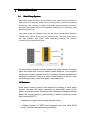
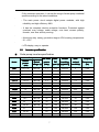
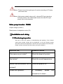
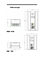
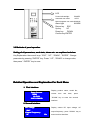
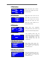
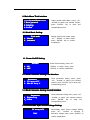
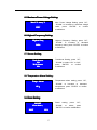
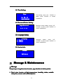
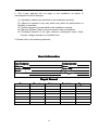
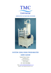
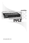
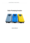
Solar Pump Inverter
Manual
1
Table of Contents
…………………………………………………………………………
Notice
Notice…………………………………………………………………………
………………………………………………………………………….. 1
......................................................................................
..6
Ⅰ Introduction
Introduction......................................................................................
........................................................................................6
...............
..6
1.1 Solar Pump system ............................................
..............................................……
……...............
.................6
...............................................
..........................................7
1.2 Features
Features...............................................
.........................................................................................7
....
..........
..8
1.3 Inverter specification
specification.. ..................................................
......................................................
..............
............8
...............................
....
wiring...............................
...................................
..............................................9
Ⅱ Installation & wiring
..................
...
2.1 Purchasing inspection ......................................
........................................................
.....................
........
......9
...................................................
.............................10
2.2 Size & Weight
Weight...................................................
................................................................................10
........................................................................
.11
2.3 Scheme of Wiring
Wiring........................................................................
.........................................................................11
................................. . ................... .…………
14
Ⅲ Operation
Operation.................................
………….....................
...................14
........................................................
……
3.1 Panel instruction
instruction........................................................
........................................................……
……..……
……...14
.......................................
......
.........
3.2 Methods of panel operation
operation.......................................
.............................................
...............
............14
.........................
..
........................................
...20
Ⅳ Storage & Maintenance
Maintenance.........................
...........................
..........................................
...........................................20
.21
................................................................................21
Ⅴ Guarantee card ...............................................................................
2
Notice
To ensure safety operation of solar pump inverter, it must choose the
right way of transportation, installation, operation and maintenance.
Before operations, be aware of the safety notices as below.
Danger: misuse may cause fire disaster, personal serious injury or
even death.
Warning: misuse may cause person with mild or moderate injury or
equipment damage.
Tips: prompt some useful information.
Check before use
�Check
Warning
If the inverter is damaged or missing parts will not be allowed to install, otherwise
may have accidents.
�Installation
Warning
1. In order to ensure good convection cooling effect, the inverter must be
mounted vertically, and leave at least 10cm space on the top and on the
bottom.
2. The inverter should be installed indoor with vents or scavenging
arrangement. Do not install under direct sunlight.
3. During installation, please do not fall drilling residual fabrics into cooling fins
or fans of inverter, to prevent the impact of cooling.
3
u
Wiring
�Wiring
Danger
1. Wiring must be carried out by qualified electrical professionals, or it may cause
electric shock or fire.
2. Before wiring, make sure the input power has been cut off, otherwise may
cause electric shock or fire.
3. Ground terminal must be connected to the ground, or the enclosure of
the inverter may have charged danger.
4. Please choose reasonable photovoltaic array, electrical load and inverter,
otherwise may cause damage to device.
Warning
1. Please use the specified torque tighten the terminal, otherwise there is a fire
hazard.
2. Please do not connect capacitance and phase ahead of LC/RC noise
filter with the output of inverter. When the distance between the
inverter and the motor load more than 100 m, it is recommended to
use the output reactor.
� Operation
Danger
1. Can be energized after confirming the wiring connected correct, otherwise
may cause inverter damage or fire.
2. Do not change the wiring in the energizing, otherwise there is a risk of
electrical shock.
4
Warning
1. Before the first run, please adjust part of control parameters according to
instruction steps of the user manual. Please do not change the control
parameter of inverter casually, or it may result in equipment damage.
2. During the operation, temperature of radiator is high, please do not
touch for a long time, otherwise there is a risk of scald.
3. When altitude height is over 1000m, the inverter should be used with
current derating. Each additional 1500m altitude, output current is
derated about 10%.
Other
�Other
Danger
1. Maintenance and Inspection must be carried out by quality electrical
professionals.
2. In energized state, do not disassemble the inverter. Waiting at least 5
minutes after power failure, maintenance and inspection can be carry out, to
avoid personal injury caused by residual voltage on electrolytic capacitor
of the main circuit.
3. Absolute prohibition of self- transformation of the inverter, otherwise it
will lead to personal injury or equipment damage.
4. Processing scrapped inverter, set the inverter as an industrial waste
processing. Internal electrolytic capacitor may explode during burning.
Some components may produce harmful, toxic gases during burning.
5
Ⅰ Introduction
1.1
Solar Pump System
Solar pump system consists of the photovoltaic array, solar pump inverter and AC
water pump. This system is widely used in pumping water for home use (drinking
& washing) , farm; irrigating for garden, field, desert plants; watering for livestock,
fish pond, landscaping streams and waterfalls, swimming pool, sea island, water
treatment projects, etc.
This system saves out of battery energy storage device, storage water instead of
storage power, directly drives pump for pumping water. This solar pump inverter
with high reliability, high power, while significantly reducing the system’s
construction and maintenance costs.
AC water pump is driven by three phase solar pump inverter. Pumping
water from deep well, rivers or lakes to water tank/pool, or to irrigation
system and fountain systems directly. According to actual demands and
installation conditions, there are various water pumps to choose, such
as centrifugal pump, mixed-flow pump, deep-well pump.
1.2 Features
Solar pump inverter controls and adjusts the working of solar pump
system, converter DC power produced by photovoltaic array to AC
power, drive water pump. According to the changing of sunlight intensity,
adjust the output frequency automatically to achieve maximum power
point tracking (MPPT).
·It applies to pumps of three phase induction motor.
·
· It adopts dynamic VI MPPT and optimized pure sine wave PWM
control, with fast response and good stability.
6
·
·Fully automatic operation, it can set the range of water pump rotational
speed according to the actual conditions.
·
· The main power circuit adopts digital power modules, with high
reliability and high efficiency 98%.
·
· It has the complete electric protective functions. Protected against
overload, over voltage, under voltage, over heat, reverse polarity,
thunder, over flow and dry running.
·
·Aluminum alloy casing, protection degree IP41,working temperature:
-10~+50℃
·
·LCD display; easy to operate.
1.2
■
Inverter specification
Solar pump inverter specification
Pump
Model
Rated
power
(kW)
Rated
voltage (V)
PV Peak
power
(kWp)
Power
Max.
Max.
tracking
DC
output
(V)[MPPT]]
current(A)
input (V)
Output
frequency
(Hz)
750L
0.37-0.75
200-220
1.1
430
300-350
5
0-60
1500 L
1.1-1.5
200-220
2.2
430
300-350
10
0-60
2200 L
2.2
200-220
3.3
430
300-350
15
0-60
3700 L
3-3.7
200-220
5.5
430
300-350
22.7
0-60
2200 H
1.5-2.2
380-440
3.3
750
500-600
7.3
0-60
3700H
3-3.7
380-440
5.5
750
500-600
11.1
0-60
5500H
4.5-5
380-440
8
750
500-600
17.1
0-60
7500H
7.5
380-440
10
750
500-600
22.2
0-60
11KH
9.2-11
380-440
15
750
500-600
34
0-60
15KH
13~15
380-440
21
750
500-600
46
0-60
18KH
18.5
380-440
25
750
500-600
50
0-60
22KH
22
380-440
30
750
500-600
60
0-60
30KH
26~30
380-440
42
750
500-600
90
0-60
37KH
37
380-440
50
750
500-600
100
0-60
45KH
40~45
380-440
60
750
500-600
120
0-60
55KH
55
380-440
75
750
500-600
130
0-60
7
Alarm: Please choose the right type of inverter according to PV array
and motor load.
Alarm: High-power models using multi - channel DC input structure,
the input power in the above table means the total DC input
power from multi-channels.
Solar pump inverter : 7500H
Output voltage (H:380V )
Rated power of adaptation motor (W)
ⅡInstallation and wiring
2.1 Purchasing inspection
We have a strict QC system in manufacturing and packing. If the inverter
cannot work, please contact with our distributor, or you can directly contact
with after-sale service department. We will solve your problem at the first time.
Please confirm the items as below when you buy the product.
Inspection item
Inspection method
If the same as your order?
Check the brand of product
Any broken?
Check the overall appearance
Inverter and accessories are all Check the product list
included?
Screws are tightened?
If
necessary,
please
screwdriver to fasten.
8
use
2.2 Size and weight
7500W 9.8 KG
750W
7KG
9
2.3 Scheme of wiring
2.3.1 With Connect to utility power function:
AC input, AC output and Sensor
Wiring diagram:
Notice:
1. When inverter’s output voltage is 3 phase/380V, AC input should connect A
phase, B phase and C phase.
2. When inverter’s output voltage is 3 phase /220V, AC input should connect
A phase and neutral wire.
Customer can use knife switch to switch utility power and solar panels. The
specification of knife switch/air switch should be twice of the rated output
current of this model. If inverter’s output power≧3700W, use knife switch; if
inverter’s output power is 750W, 1500W and 2200W, use air switch.
10
2.3.2 Without connect to utility power function
AC output, Sensor
Wiring diagram:
11
Warning: In order to ensure system work normally and properly,
please use recommended wires with different size as below.
Model No
750L
1500 L
2200 L
3700 L
3700H
5500H
7500H
11KH
Battery
board wire
2.5mm2
2.5 mm2
2.5 mm2
4 mm2
2.5 mm2
Rated voltage
750V
4 mm2
Rated voltage
750V
4 mm2
Rated voltage
750V
8 mm2
Rated voltage
750V
Ground wire
Motor wire
Sensor wire
2.5 mm2
2.5 mm2
2.5 mm2
4 mm2
2.5 mm2
Rated voltage
750V
4 mm2
Rated voltage
750V
4 mm2
Rated voltage
750V
8 mm2
Rated voltage
750V
2.5 mm2
2.5 mm2
2.5 mm2
4 mm2
2.5 mm2
0.5-1.0 mm2
0.5-1.0 mm2
0.5-1.0 mm2
0.5-1.0 mm2
0.5-1.0 mm2
4 mm2
0.5-1.0 mm2
4 mm2
0.5-1.0 mm2
6 mm2
0.5-1.0 mm2
12
◆ Outer plug instruction:
Plug
Wire instruction
red wire
single strand
Connecting
connected positive
pole of PV array
black wire
single strand
connected negative
pole of PV array
4
core
wire
8
Core
wire
(network
cable
Red 4.0 mm2
Green 4.0 mm2
Blue 4.0 mm2
Yellow-green
blue
red
White-green,
A phase
B phase
C phase
ground wire
tank sensor high
tank sensor middle
tank sensor ground
wire
white-red
green
brown
White-green
well sensor high
well sensor middle
well sensor ground
wire
White-brown
Ⅲ Operation
3.1 Panel instruction
Solar pump inverter is LCD displayed, see as below diagram, including 4 LED
lights, 1 LCD panel and 4 keys, Simple operation, easy understanding.
13
LCD
Power indicate light
POWER
Automatic run mode
AUTO
Manual operate run mode MANUAL
Alarm light
ALARM
Return key ESC
Up key
UP
Down key
DOWN
Confirm key ENTER
3.2 Methods of panel operation
Setting of all parameters, work state, alarms etc. are explained as below.
Key Explanation: there are 4 keys: ‘’ESC’’, ‘’UP’’, ‘’DOWN’’, ‘’ENTER’’. Change
parameter by pressing ‘’ENTER’’ key. Press ‘’ UP’’, ‘’DOWN’’ to change value,
then press ‘’ ENTER’’ key to save.
Detailed Operation and Explanation For Each Menu
1. First Interface:
Display product name, model No.,
Pump Inverter
0H
750
7500H
19
19::52
52::21
D
2012Y1
2012Y111M03
03D
current
time
and
date,
press
‘’DOWN’’ key to enter into second
interface.
2. Second Interface
Interface:
DC voltage
voltage::
V
500
00V
Output Frequency
requency::
50
Display current DC input voltage, AC
14
Hz
output frequency, press ‘’DOWN’’ key to
enter into third interface.
3. Third Interface:
Display saved power value, reduced
Saved power
power::
4250.1
Reduced CO2:
2890.0
h
KW
KWh
Kg
4. Fourth Interface
Interface:
Tank sensor
NO
Well sensor
NO
CO2 value, press ‘’DOWN’’ key to enter
into fourth interface.
Display tank sensor state and well
sensor state, you can choose “NO” or
“OK”, if you choose “OK”, the tank
sensor and well sensor can work,
default “NO”, press ‘’DOWN’’ key to
enter into fifth interface.
5. Fifth Interface
Interface:
Inner temp
temp..:
us
Stat
Status
us::
Now
0
30.2
30.2℃
Automatic
Alarm
Alarmss
>>
Check
Check>>
Display
device
inner
temperature,
working state, alarm, press ‘’ENTER’’ key
to enter into password setting interface.
6. Enter Password
Password::
Input Password
Password:
0000
Enter password before enter into
system menu, Press ‘’UP’’ ‘’DOWN’’ to
enter 4 correct password to enter into,
default password:0000, user can
change password after enter into
system menu.
7. Main Menu First Interface
Interface:
System Menu======
=====
=====System
1. Work mode
2. ON/OFF
3. Parameters
Under System Menu, press ‘’UP’’,
‘’DOWN’’ to select your wanted content,
press ‘’ENTER’’ key to enter into
corresponding menu.
8. Main Menu Second Interface
Interface:
=====System Menu======
Alarm
4. Temp.
Temp.Alarm
15
5. RESET
6. Time
Under System Main Menu, press ‘’UP’’,
‘’DOWN’’ to select your wanted content,
press ‘’ENTER’’ key to enter into
corresponding menu.
9. Main Menu Third Interface
Interface:
=====System Menu======
7. Reset password
8. Language
9. Version
Under System Main Menu, press ‘’UP’’,
‘’DOWN’’ to select your wanted content,
press ‘’ENTER’’ key to enter into
corresponding menu.
10. Work Mode Setting:
Work mode
1. Manual
2. Automatic
Setting system work mode, press
‘’UP’’, ‘’DOWN’’ to select mode,
press ‘’ENTER’’ key to confirm
modification.
11. Power On/Off Setting:
ON/OFF
1. ON
2. OFF
Power On/Off setting, press ‘’UP’’,
‘’DOWN’’ to select mode, press
‘’ENTER’’ to confirm modification.
12. Work Parameter Setting First Interface
Interface:
Parameters
1. PV Array OCV
2. Max PV Array V
Work parameter setting menu, press
‘’UP’’, ‘’DOWN’’ to select your wanted
content, press ‘’ENTER’’ key to enter into
corresponding menu.
13. Work Parameter Setting Second Interface
Interface:
Parameters
Highest Freq
3、Highest
Sensor
4、Sensor
Work parameter setting menu, press ‘’UP’’,
‘’DOWN’’ to select your wanted content,
press ‘’ENTER’’ key to enter into
corresponding menu.
14. Photovoltaic Open Circuit Voltage Setting:
PV Array OCV
16
750V
Photovoltaic Open Circuit Voltage Setting,
press ‘’UP’’, ‘’DOWN’’ to increase or
decrease voltage value, press ‘’ENTER’’ to
confirm modification.
15. Maximum Power Voltage Setting
Setting::
Max PV Array V
Max. Power Voltage Setting, press ‘’UP’’,
‘’DOWN’’ to increase or decrease voltage
value, press ‘’ENTER’’ to confirm
modification.
0V
48
480V
16. Highest Frequency Setting:
Highest Freq
Highest Frequency Setting, press ‘’UP’’,
‘’DOWN’’ to increase or decrease
frequency value, press ‘’ENTER’’ to confirm
modification.
50Hz
17. Sensor Setting:
Tank Sensor
NO
Well Sensor
NO
Transducer Setting, press ‘’UP’’,
‘’DOWN’’ to select “OK” or “NO”,
press ‘’ENTER’’ to confirm
modification.
18. Temperature Alarm Setting:
Temp
Temp.. Alarm
Temperature alarm setting, press ‘’UP’’,
‘’DOWN’’ to increase or decrease
temperature, press ‘’ENTER’’ to confirm
modification.
85
85℃
19. Reset Setting:
RESET
Clear data
data?
EXIT
Reset setting, press ‘’UP’’,
‘’DOWN’’
to
select,
press
‘’ENTER’’ to confirm modification.
YES
17
20. Time Setting:
Time
Time setting, press ‘’UP’’, ‘’DOWN’’ to
select, press ‘’ENTER’’ to confirm
modification.
58
32
21
21:58
58:32
2012Y04M19D
21. Password Revise Setting:
Input Password
Password:
Password revise setting, press ‘’UP’’,
‘’DOWN’’ to select, press ‘’ENTER’’ to
confirm modification.
0 0 0 0
22. Language Setting:
Language
1. English
2. Chinese
Language
setting,
press
‘’UP’’,
‘’DOWN’’ to select, press ‘’ENTER’’ to
confirm modification.
23. Version Info:
Version
REV 10.14
Ⅳ Storage & Maintenance
◆ Storage
Temporary or long-time store inverter, pay attention to below points:
1. Don
Don’’t store inverter at high temperature, humidity, shake, metallic
dust place, ensure well ventilated place.
18
2. If long-time no use, inner filter characteristics of the inverter will
decay. Every two years through the electrical power to restore the
filter characteristics, and check the inverter functionality. In power
turn-on, voltage should be gradually increased through a DC power
supply, and power-on time is not less than five hours.
3. Warranty
Setec warrants that this product is free from defects in material and
workmanship and agrees to remedy any defect (or at its option replace
s from the date of purchase. Parts may
the product) for a period of 2 year
years
be replaced under this warranty with new or remanufactured parts.
Beyond the warranty period, Setec also provides life-long paid service.
This 2-year warranty will not apply to the conditions as
d.
below. A maintenance fee will be charge
harged.
manual);
1. Improperly installed (as described in the installation manual)
2. Altered or repaired in any way which may affect the performance or
reliability of operation
operation;
3. Stored improperly (as described in the installation manual)
manual);
M
isused,
abused,
used
in
ways
the
product
was
not
designed
4.
designed;
5. Damaged because of fire, gas corrosion, earthquake, storm, flood,
thunder, voltage anomaly or irresistible force.
Note: Warranty only covers inverter device.
Guarantee Card
In order to ensure good quality, we do strict inspection before leaving factory.
We warrant that this product is free from defects in material and workmanship
and agree to remedy any defect for a period of 2 years from the date of
purchase.
1. Parts may be replaced under this 2 years warranty with new or
remanufactured parts when the damaged is checked by our technicians.
Damaged parts should be returned to us.
19
2. This 2-year warranty will not apply to the conditions as below. A
maintenance fee will be charged.
(1). Improperly installed (as described in the installation manual);
(2). Altered or repaired in any way which may affect the performance or
reliability of operation;
(3). Stored improperly (as described in the installation manual);
(4). Misused, abused, used in ways the product was not designed;
(5). Damaged because of fire, gas corrosion, earthquake, storm, flood,
thunder, voltage anomaly or irresistible force.
3. Please refer to the warranty statement.
User
User’’s Information
User Company:
Address:
Dealer company:
Model:
Purchase date:
Contact person:
Phone:
Post code:
Serial number:
Handling person:
Repair Record
Date
Record
Abstract
20
Technician
Signature