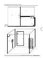
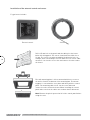
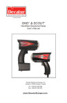
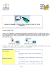
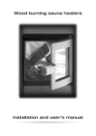
1
Installation and Operating
Instructions
Pipe C- and E-types
10/2014
Contents:
2
1General safety information 2 Pipe C- and E-types 3The assembly and installation of the heater Stacking of the stones 4 Technical information The power and connections of the heater Heater dimenstions Amount of heater stones Minimum distances to flammable material 5 General instructions for the Pipe heater users Attention Installation cable Additional connection options 6 Consider the following when using the heater First heating Sauna room Temperature control Heating time Water thrown on heater Sauna room structure 7 Wiring diagram C-type 8The operation of the clock timer and thermostat
of the C-type Further wiring possibilities 9 Installation instructions E- type Installation of the external control and sensor 10 Wiring diagram E-type Connecting the controller card in the heater Connecting the controller card in the controller 11 Control and operation of the heater E-type First-time use / calibration Resetting the heater Fault codes Temperature limiter 12 Troubleshooting In case the heater does not warm up Warnings Warranty Maintenance, spare parts Natural stone as material 13 Service history Installation and Operating Instructions Pipe
3
4
5
5
6
6
6
6
7
8
8
8
8
8
8
8
8
8
8
9
9
10
10
11
12
13
13
13
14
14
14
14
14
15
15
15
15
15
15
16
1. General safety information
For safe use of sauna, please read these safety instructions first!
Electrical connections can only be done by an electrician authorized to installation according
to the current regulations.
The MONDEX electric heater is suitable for use in a family sauna, one (1) heater/sauna room.
Preserve the installation and operating instructions for future reference.
Always check the adequacy of fire protection distances!
Failure to observe the wiring instructions may result in a fire risk!
Always remember to check the sauna room before turning the heater on!
Always check whether the controller has switched off the power after the set time period!
Due to the risk of fire do not use the sauna as a drying room for clothes or laundry.
Be careful with the hot heater as the stones and metal parts become very hot and can
cause burns.
Steam from the heater is burning hot and may cause burns.
It is recommended to supervise children, disabled and ill persons that are using the sauna.
Benches and floors may be slippery, therefore move in the sauna with caution.
Do not go to a hot sauna under the influence of narcotic substances (alcohol, drugs,
narcotics, etc.)
The heater’s improperly filled area for stones is a fire hazard.
Covering causes a fire risk.
This device is not intended for children or people whose physical, sensory or mental capabilities, or
lack of experience and knowledge prevents them from using the device safely, without the supervision
of a person responsible for their safety or before they have been instructed on how to use the device.
Children should be supervised to ensure that they do not play with the device.
This device complies with the requirements of:
Mondex pursues an active policy of product development and improvement. For this reason, Mondex
reserves the right to make changes relating to the design and technical specification of their products
without prior notice.
Installation and Operating Instructions Pipe
3
2. Pipe heater types
+
4
C-type
Installation and Operating Instructions Pipe
E-type
3. The assembly and installation of the heater
1) The package includes the heater (E-type also an external control unit) and its user manual. Heater stones are not included.
2) Inspect the heater visually and if you notice any discrepancies, please contact the store from where you purchased the heater or [email protected]
3) The sauna’s floor surface should be properly protected before starting the installation.
4) The electrician connects the wires before the heater is installed
to its place. During the heater’s installation observe the safety
distances between the heater and combustible material as in
Table 4.4. (see pg 7) as well as the heater’s power rating according to Table 4.1 (see pg 6).
5) The heater should be installed on the floor and its feet should be adjusted so that the heater is upright.
5
Stacking of the stones
Note! Use regular olivine diabase, peridotite or olivine heater stones of less than 10 cm ø in the PIPE
heater. It is recommended to use protective gloves when stacking the stones. The heater stones should
be stacked so that the resistors are not touching each other. The resistors should never be bended so
that they would touch the metal structures of the stove.
The heater’s area for stones should be entirely filled with stones, including the internal parts of the
resistor column. The stones should be stacked in layers starting from the bottom of the heater.
Continue filling the area step-by-step in this manner until all of the stones have been placed.
When stacking the stones, please do not batter on the heater’s metal surfaces so to avoid damage.
Dents caused by the user are not covered by the manufacturer’s warranty or other product liability.
Installation and Operating Instructions Pipe
4. Technical information
Heater
Pipe 6,6
Pipe 9,0
Pipe 10,5
Power kW
6,6
9,0
10,5
Voltage
400 V 3N
400 V 3N
400 V 3N
Connecting cable
5 x 1,5 mm²
5 x 2,5 mm²
5 x 2,5 mm²
Fuse
3 x 10 A
3 x 16 A
3 x 16 A
Size of the sauna
6 - 9 m3
8 - 15 m3
12 - 22 m3
Table 4.1
Kiukaan mitat (mm)
Model
Diameter
Height
Pipe 6,6
320
850
Pipe 9,0
320
850
Pipe 10,5
370
1100
Table 4.2
6
Amount of stones
Model
Type Stone amount (kg)
Pipe 6,6
80
Pipe 9,0
80
Pipe 10,5
140
Table 4.3
Installation and Operating Instructions Pipe
Minimum distances from combustible material (mm)
C
A
A
B
B
D
7
Model
A
B
C
D
Size of the sauna
Pipe 6,6
100
100
770
1900
6-9 m³
Pipe 9,0
120
120
770
1900
8-15 m³
Pipe 10,5
180
180
900
2000
12-22 m³
Table 4.4 Minimum distances to combustible material (mm)
Installation and Operating Instructions Pipe
5. General instructions for the Pipe-heater users
Attention!
The electrical connections may only be done by an electrician authorized to installation according to
the current regulations. The Pipe electric heater is suitable for use in a family sauna, one (1) heater
per sauna room. Preserve the installation and operating instructions for future reference.
Installation cable
Use rubber cable H07RN-F as a connecting cable.
Additional connection options
Control of electric heating with the heater: The electric heating control cable is brought directly to
the heater’s junction box and then further to the heater’s terminal block with a rubber cable that is as
strong as the connecting cable.
NOTE! Failure to observe the wiring instructions may result in a fire risk!
NOTE! Remove all plastic foil before starting to use the heater!
6. Consider the following when using the heater
First heating
8
During the first heating resistors can emit fumes, therefore you should see to it that the room’s
ventilation and air conditioning are functional. NOTE! See also the first time use of type E on p. 14!
Sauna room
Always remember to check the sauna room before turning the heater on! Always make sure that the
timer has switched off the power after the set time period!
Temperature control
The desired temperature can be set either by a mechanical thermostat (see page 10 types C) or
through the control panel (see page 14 E types). The actual heating time is affected by the sauna’s
dimensions, structure and thermal insulation. The temperature in the sauna room can be maintained
at the desired level with a thermostat. Should the temperature of the sauna room, for any reason,
become dangerously high, the automatic temperature overheat protector will turn off power from the
heater. Always find out the cause of overheating. Power can be turned on again by pressing the overheat protector reset button (see page 10 types C and page 14 types E).
Heating time
Heating the sauna too long consumes energy and does not improve the steam’s properties. The best
steam is achieved by keeping the sauna’s heating time relatively short, namely 30-60 min. according
to the size of the sauna and the heater’s power. Size of the sauna, glass doors, windows, or materials
used may increase the heating time.
Water thrown on heater
We recommend using hand-warm water. The water used for throwing on heater should be household
water. Smoother steam can be achieved by throwing the water to the heater sides / lower stones. If you
want tougher and more aggressive steams pour plenty of hot water all at once on the heater.
Installation and Operating Instructions Pipe
Sauna room structure
Sauna and especially its roof should have good thermal insulation, as the steam tends to escape
through the roof. Due to moisture we recommend using aluminium foil. The heater is dimensioned
according to the sauna space.
In addition to the conventional sauna structure (wool insulation, foil, timber), the power consumption
is also affected by the following. If the sauna has walls made of uninsulated stone, tile or concrete
surfaces or timber, the heater power should be slightly increased.
Power consumption increases for every uninsulated square meter the same amount as if increasing space by 1.2 m3 and on timber surfaces by 1.5 m3. Also the glass surfaces (glass walls, doors and
uninsulated stone surfaces) are calculated as 1.2 m3 per square meter. Choose a higher-powered
heater in borderline cases.
The sauna needs efficient ventilation in order to achieve good oxygen levels and fresh air. Air in the
sauna room has to change 6 times/h. We recommend to place the valved fresh air tube above the
heater. The exhaust valve should be installed as far away from the heater as possible and close to
the floor limit. It is also possible to lead the exhaust air to the washroom from under the door. In this
case there must be at least 50 mm of space under the sauna door and the washroom should have an
exhaust valve.
For more information, see the construction guidelines and building regulations.
9
7. Wiring diagram for C-types (fixed control)
Heat control
Sign light “heater on”
Installation and Operating Instructions Pipe
8. The operation of the clock timer and thermostat of the C-type
Time switch
Thermostat
Overheat protectors
reset switch
10
The time switch (4+8 h) operates as the heater’s main switch. After the desired time the time switch
automatically turns the power off from the heater. If you wish the heater to warm up after a set time,
you can set the timer to start the warm-up after 1-8 hours. The maximum warm-up time is 4 hours.
For example:
If you want to go to the sauna as soon as possible, set the time switch between 1 - 4. The heater
switches on immediately and begins to warm up. The desired temperature can be set by turning the
thermostat.
For, example, if you want to go to the sauna after three hours, set the timer to 2 on the time switch 1-8.
The timer starts and the power will be turned on and the heater will start to warm up after two hours.
When power has been turned on, the heater will remain on for up to 4 hours. After this power will be
turned off automatically. If desired, power can be switched off earlier by turning the time switch to zero (0).
Always make sure that the time switch has turned power off after the set time period!
Additional connection options
Wiring a signal light outside the sauna room
For example the cable H07RN-F should be used as connection cable and its cross-sectional area
should be the same as the connecting cable’s.
Control of electric heating with the heater
The electric heating control cable should be brought directly to the heater’s junction box and then further to the heater’s terminal block with a rubber cable strong as the connecting cable.
Installation and Operating Instructions Pipe
9. Installation instructions E- type
PH
KHH
Controller
S
Sensor
RK
Supply cable 5 x 1.5 mm2 / 5 x 2.5 mm2
11
ca. 250 mm
ca. 250 mm
max. 990 mm
Controller
Installation and Operating Instructions Pipe
Installation of the external control and sensor
E-type heater includes:
External control
12
Sensor
Drill a 3,5 mm hole to the panel and then bring it to the heater
below the wiring panel. The sensor should remain visible for ca
10 mm. The sensor can when needed be fixed into the hole, for
example, with a small drop of silicone adhesive. The sensor cable
measures 6 m. Cut the excess wire and connect the other end to
the heater.
The wall mounting plate is either mounted with three screws to
the wall or fixed to the bottom of the mounting box. The mounting plate is covered with a cover plate and finally with the control
panel. The mounting cable is 8 m. Cut the extra cable and
connect the other end to the heater. When installing the control
panel make sure that the cables are not detached or deformed.
Note! Remove the plastic protection foil of the control panel before
using the stove.
Installation and Operating Instructions Pipe
10. Wiring diagram E-type
OVERHEATING PROTECTION
Connecting the controller card in the
heater
Connecting the controller card in
the controller
Prepared quick
connector
White
Grey
Green
Blue
Red
White
White
Black
Black
To the controller
To the overheating protection
To the thermal sensor
Installation and Operating Instructions Pipe
13
11. Control and operation of the heater E-type
Power switch
Quick start
Temperature
control
Operating time
Temperature
Operating time adjustment
The heater is operated by adjusting its operating time and temperature and then switching the heater on from
the power switch.
Normal start: Select the operating
time with control buttons .
Operating time is displayed in light studs.
One light equals 30 min.
Maximum operating time is 4h.
14
Quick start: Push the quick start button.
The heater will remain on for two hours.
Temperature control: Set the desired
temperature with control buttons .
One light stud affects the temperature by ca. 5°C.
Heater start-up: When the operating time
and temperature have been set, turn on the
heater from the power switch. NOTE! In case
the power switch has not been pressed, controller
lights will be blinking. NOTE! The heater memorizes
the previous temperature setting.
Scheduling the heater: The heater can be scheduled
to start after 30 min – 8 h. After this the heater will
remain on for 4 h.
When 2 hours have passed or the blue led at right
hand corner below is gone out, the stove is calibrated.
Do not open the sauna door during the calibration.
During the calibration the heater learns to heat itself
optimally according to the volume of the sauna. After
the calibration the heater can be used normally.
Resetting the heater
Turn off the main switch of the heater (located on
the right hand lower side of the heater). Press the
heater’s temperature + and – buttons at the same
time. Put on the main switch of the heater on again
by at the same time pressing the + and – buttons. No
the heater is ready for a new calibration. Look at the
instructions about calibration at the “First-time use
of the heater.
Fault codes
In case of a fault in the heater, the electronics turn
off the heating elements and notify the controller of
the failure with blue lights as follows:
4.lower light:
Relay fault
• Keep the operating time controller pressed until
the red lights end.
• After this the light studs will turn blue and each
light represents 30 min of time.
• Select the desired temperature for the sauna with
the temperature control buttons.
• You can turn off the heater at any time
by pressing the power switch.
3. lower light:
Short circuit of the
thermal sensor
First-time use of the heater
(the heater’s calibration):
Temperature limiter
Set the temperature from the temperature control 2
leds from below. Push the quick-start button (2h). Put
the heater on from the left upper corner power switch.
Installation and Operating Instructions Pipe
2. lower light:
Contact failure of
the thermal sensor
1. lower light:
Calibration status
The temperature limiter reset button is located above
the heater’s main power switch under a protective
cap. Open the protective cap by turning it. Red reset
button located under the cap is 3.5 mm thick.
12. Troubleshooting
- Is the power on?
- Has the temperature limiter tripped ? -> This is reset by pressing the temperature limiter reset switch with a thin-headed object until a click is heard. One should always find out the reason for the temperature limiter tripping before the unit is switched on again.
- Has the time switch been turned to the point where the heater should warm up?
- Are the heater’s main fuses in the electrical unit intact?
- Has the thermostat been set to higher values than the sauna temperature?
- Has the time switch stopped or stuck (for example stuck in the front panel)?
-> The suitable gap is 1-2 mm.
- Check that all the resistors are glowing when the heater is on.
- Check the fault codes in Models E.
If necessary, contact the dealer or manufacturer.
Warnings
- Due to the fire risk do not use the sauna as a drying room for clothes or laundry.
- Be careful with the hot heater as the stones and metal parts become very hot and can cause burns.
- Steam from the heater is burning hot and may cause burns.
- It is recommended to supervise children, disabled and ill persons that are using the sauna.
- Benches and floors may be slippery, therefore move in the sauna with caution.
- Do not go to a hot sauna under the influence of narcotic substances (alcohol, drugs, narcotics, etc.).
Maintenance, spare parts
15
If insolvable faults appear in the heater, please contact the manufacturer or service centre. Spare
parts are available from the MONDEX distributors, service centre and manufacturer. When purchasing
spare parts, please note down the name and power of the heater, so that the right parts can be
supplied.
Natural stone as material
Small pebbles or pieces can come off the natural stone used in the heater. As this is not a failure of
the organic material but its natural feature that cannot be predicted at the time of manufacturing the
product, the manufacturer is not responsible for any damage resulting from this.
Warranty
For its heaters and control units in private use, the manufacturer Mondex Oy, grants a warranty of two
(2) years from date of purchase. The warranty is limited to (1) year if these products are in commercial use. Preserve the sales receipt or warranty card. The warranty does not cover external or internal
mechanical damage caused by, for example, impacts with a stone or the heater falling over. Nor does
the warranty cover defects cause by nature like lighting or damages caused by overvoltage.
Installation and Operating Instructions Pipe
The heater’s service history
We recommend replacing, among other things, the heater stones every 1-2 years.
Date
The heater’s manufacturer:
Mondex Oy
Rantakatu 14 A
67100 Kokkola
Finland
tel. +358 6 8244 333
fax. +358 6 8322 355
[email protected]
www.mondex.fi
Action