1
2100802-001 (AB)
TOTALFLOW®
XSeries Remote Controller
User's Manual
Intellectual Property & Copyright Notice
©2002, 2007 by ABB Inc., Totalflow (“Owner”), Bartlesville, Oklahoma 74006, U.S.A. All
rights reserved.
Any and all derivatives of, including translations thereof, shall remain the sole property of
the Owner, regardless of any circumstances.
The original US English version of this manual shall be deemed the only valid version.
Translated versions, in any other language, shall be maintained as accurately as possible.
Should any discrepancies exist, the US English version will be considered final.
Notice: This publication is for information only. The contents are subject to change without
notice and should not be construed as a commitment, representation, warranty, or
guarantee of any method, product, or device by Owner.
Inquiries regarding this manual should be addressed to ABB Inc., Totalflow Products,
Technical Communications, 7051 Industrial Blvd., Bartlesville, Oklahoma 74006, U.S.A.
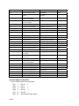
Table of Contents
Introduction ............................................................................................................ ix
About the Manual ........................................................................................................ ix
Getting Help..................................................................................................................x
Key Symbols.................................................................................................................x
Safety Practices and Precautions................................................................................ xi
Chapter 1 System Description ............................................................................1-1
Overview................................................................................................................... 1-1
XSeries Remote Controller Hardware ...................................................................... 1-2
Standard Enclosure .................................................................................................. 1-4
Rack Mount Enclosure.............................................................................................. 1-7
XRC General Specifications ..................................................................................... 1-8
XRC-195 Electronic Board Specifications ................................................................ 1-9
XSeries On-board Input/Output .............................................................................. 1-11
Digital Output .......................................................................................................... 1-13
Analog Inputs.......................................................................................................... 1-14
Display Function ..................................................................................................... 1-15
Functions of the XRC.............................................................................................. 1-16
Display Annunciators .............................................................................................. 1-17
Laptop Computer running PCCU32........................................................................ 1-20
FS/2 Handheld PCCU............................................................................................. 1-20
Optional Equipment .................................................................................................. 1-21
Key Pad .................................................................................................................. 1-21
Totalflow Input/Output Modules .............................................................................. 1-24
Chapter 2 Installation ..........................................................................................2-1
Overview................................................................................................................... 2-1
Unpacking & Inspection ............................................................................................ 2-1
Pipe Saddle Mount Installation ................................................................................. 2-2
Wall Mount Installation.............................................................................................. 2-6
Battery Pack Installation ........................................................................................... 2-8
Solar Panel Installation ........................................................................................... 2-10
AC Charging Unit Installation.................................................................................. 2-12
XRC6990 Rack Mount Installation.......................................................................... 2-15
XRC Communication, Jumper Settings and Field Wiring ....................................... 2-17
Chapter 3 XRC Startup ........................................................................................3-1
Overview................................................................................................................... 3-1
PCCU32 Installation and Setup ................................................................................ 3-2
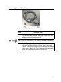
Connecting To Local Port ......................................................................................... 3-2
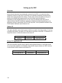
Setting up the XRC...................................................................................................... 3-4
Overview................................................................................................................... 3-4
i
Station ID.................................................................................................................. 3-4
Device ID / Application ID......................................................................................... 3-4
Location .................................................................................................................... 3-5
Date/Time ................................................................................................................. 3-5
Program Display ....................................................................................................... 3-5
Security System........................................................................................................ 3-6
On Board I/O Calibration ............................................................................................ 3-8
Overview................................................................................................................... 3-8
Analog Input Calibration ........................................................................................... 3-8
Pulse and Digital Input Calibration ......................................................................... 3-10
Chapter 4 Maintenance ....................................................................................... 4-1
Overview................................................................................................................... 4-1
Backing up Configuration Files................................................................................. 4-2
Changing XRC Clock................................................................................................ 4-2
Downloading a New Flash........................................................................................ 4-3
Components and Spare Parts .................................................................................. 4-4
Replacing XRC Battery Pack.................................................................................... 4-8
Replacing Liquid Crystal Display (LCD) Board....................................................... 4-13
Chapter 5 Troubleshooting ................................................................................ 5-1
Overview................................................................................................................... 5-1
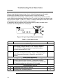
Troubleshooting Visual Alarm Codes ....................................................................... 5-4
Overview................................................................................................................... 5-4
Troubleshooting a Blank LCD Screen ...................................................................... 5-5
Troubleshooting a Low Lithium Alarm (LL)............................................................... 5-6
Troubleshooting a Low Charger Alarm (LC)............................................................. 5-7
Troubleshooting a Analog to Digital Failure Alarm (AD) ........................................... 5-7
Resistive Temperature Detector (RTD) Continuity Test ........................................... 5-9
RTD Current Source (Resistive) Test..................................................................... 5-10
RTD Impedance Test ............................................................................................. 5-11
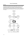
Power Troubleshooting ............................................................................................ 5-12
Overview................................................................................................................. 5-12
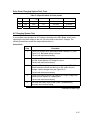
Power Supply Test ................................................................................................. 5-13
Solar Panel Charging System Test ........................................................................ 5-13
AC Charging System Test ...................................................................................... 5-15
Auxiliary Equipment Isolation Test ......................................................................... 5-16
TFIO Module Isolation Test .................................................................................... 5-17
SLEEP Mode .......................................................................................................... 5-18
Reset Procedures................................................................................................... 5-19
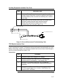
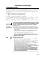
Troubleshooting Communications.......................................................................... 5-21
Communications Overview..................................................................................... 5-21
Transceiver Supply Voltage Test............................................................................ 5-23
ii
12V Communication Supply Voltage Test .............................................................. 5-23
Transceiver Check.................................................................................................. 5-25
RS-232 Communication Test.................................................................................. 5-25
RS-485 Communication Test.................................................................................. 5-27
RS-485 Communication Test.................................................................................. 5-27
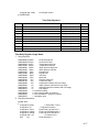
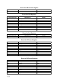
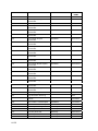
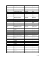
Appendix A Register Documents ...................................................................... A-1
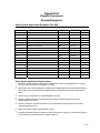
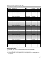
Standard Registers .....................................................................................................A-1
Alarm System Application Registers (Rev AB) ......................................................... A-1
Display Application Registers (Rev AA).................................................................... A-5
Holding Register Application (Rev AA) ..................................................................... A-7
Operations Application Registers (Rev AB).............................................................. A-8
System Application Registers (Rev AD) ................................................................. A-21
Trend System Application Registers (Rev AA) ....................................................... A-24
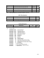
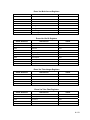
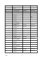
Communication Registers........................................................................................A-26
Communication Application Registers (Rev AA) .................................................... A-26
FS2 Application Registers (Rev AA)....................................................................... A-28
XMV Interface Application Registers (Rev AC) ...................................................... A-33
Therms Master Application Registers (Rev AB) ..................................................... A-37
Therms Salve Application Registers (Rev AA) ....................................................... A-52
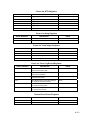
I/O Subsystem ...........................................................................................................A-57
I/O Subsystem Data Array Registers...................................................................... A-57
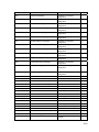
Tube Applications .....................................................................................................A-66
AGA3 Tube Application Registers (Rev AM) .......................................................... A-66
AGA7 Tube Application Registers (Rev AH) .......................................................... A-82
Enron Tube Registers (Rev AA) ............................................................................. A-98
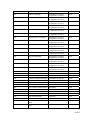
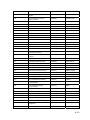
Selectable Units.......................................................................................................A-122
AGA3 Selectable Units Tube Registers (Rev AE) ................................................ A-122
AGA7 Selectable Units Tube Registers (Rev AD) ................................................ A-142
Enron AGA3 Selectable Units Tube Registers (Rev AA)...................................... A-164
Appendix B Definitions & Acronyms ................................................................ B-1
Appendix C Drawing & Diagrams ...................................................................... C-1
iii
B
Bllaannkk P
Paaggee
iv
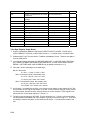
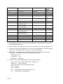
Table of Figures
Figure 1–1 Model XRC6490.............................................................................................. 1-4
Figure 1–2 Model XRC6790.............................................................................................. 1-5
Figure 1–3 Model XRC6890.............................................................................................. 1-6
Figure 1–4 XRC6990 Rack Mount .................................................................................... 1-7
Figure 1–5 Complete View XRC-195 Board ................................................................... 1-10
Figure 1–6 Liquid Crystal Display and Indicators............................................................ 1-18
Figure 1–7 Optional Keypad (P/N 2100652-xxx) ............................................................ 1-22
Figure 1–8 XRC6490 with Optional Key Pad .................................................................. 1-22
Figure 1–9 XRC6790 With Optional Keypad................................................................... 1-23
Figure 1–10 XRC6890 With Optional Keypad................................................................. 1-23
Figure 1–11 XRC6990 with Dual Keypads...................................................................... 1-24
Figure 1–12 TFIO Module Housing................................................................................. 1-25
Figure 1–13 XRC6490 Inside View ................................................................................. 1-25
Figure 1–14 XRC6790 Inside View ................................................................................. 1-26
Figure 1–15 XRC6890 Inside View ................................................................................. 1-26
Figure 1–16 XRC6990 Inside View ................................................................................. 1-27
Figure 2–1 Typical Pipe Saddle Installation ...................................................................... 2-3
Figure 2–2 Model XRC6490, Pipe Mounted ..................................................................... 2-4
Figure 2–3 Model XRC6790, Pipe Mounted ..................................................................... 2-4
Figure 2–4 Model XRC6890, Pipe Mounted ..................................................................... 2-5
Figure 2–5 XRC Pipe Mounting ........................................................................................ 2-5
Figure 2–6 Model XRC6490, Wall Mounted...................................................................... 2-7
Figure 2–7 Model XRC6790, Wall Mounted...................................................................... 2-7
Figure 2–8 Model XRC6890, Wall Mounted...................................................................... 2-8
Figure 2–9 XRC-195 Board Battery and Charger Input Connections ............................... 2-9
Figure 2–10 Typical Solar Panel Installation................................................................... 2-10
Figure 2–11 Mounting AC Charger ................................................................................. 2-13
Figure 2–12 DC Wiring Instructions ................................................................................ 2-14
Figure 2–13 AC Wiring Instructions ................................................................................ 2-14
Figure 2–14 XRC6990 Rack Mount ................................................................................ 2-15
Figure 2–15 Single and Dual Unit Termination Panels ................................................... 2-16
Figure 2–16 XRC Standard Communication Wiring........................................................ 2-17
Figure 2–17 XRC Panel Mount Field Wiring Diagram..................................................... 2-18
Figure 2–18 XRC Main Electronic Board Jumper Configuration..................................... 2-20
Figure 2–19 Other Field Wiring I/O Connections ............................................................ 2-21
Figure 3–1 RS-232 MMI Communication Cables.............................................................. 3-3
Figure 3–2 XRC-195 Board- Analog Input Calibration Points ........................................... 3-9
Figure 3–3 195 Board- Analog Input Calibration Points.................................................. 3-10
Figure 4–1 XRC6490 Component/Cable Locations .......................................................... 4-4
Figure 4–2 XRC6890 Component/Cable Locations .......................................................... 4-5
Figure 4–3 Memory Backup Enable Jumper..................................................................... 4-8
Figure 4–4 XRC Battery and Charger Connections .......................................................... 4-9
v
Figure 4–5 XRC Board Connections................................................................................4-12
Figure 5–1 Troubleshooting Flowchart ..............................................................................5-3
Figure 5–2 Liquid Crystal Display and Indicators...............................................................5-4
Figure 5–3 Battery Charger and Battery Pack Connections ..............................................5-6
Figure 5–4 Power Troubleshooting Flowchart .................................................................5-12
Figure 5–5 AC-DC Charger Wiring Instructions ...............................................................5-16
Figure 5–6 Current Measurement Troubleshooting Cable...............................................5-17
Figure 5–7 Lithium Battery Backup Enable/Disable.........................................................5-20
Figure 5–8 Communication Troubleshooting Flow Chart.................................................5-22
Figure 5–9 XRC-195 Communication Wiring...................................................................5-24
vi
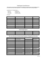
List of Tables
Table 1–1 XRC Board Component Descriptions............................................................. 1-11
Table 1–2 Typical XRC Display Options ......................................................................... 1-16
Table 1–3 Status and Alarm Description......................................................................... 1-18
Table 2–1 XRC Main Electronic Board to Termination Panel Correlation Chart............. 2-16
Table 2–2 XRC On-Board Jumper Settings .................................................................... 2-19
Table 3–1 XRC Displayed Items ....................................................................................... 3-5
Table 4–1 XRC6490 and 6890 Component Identifications ............................................... 4-6
Table 4–2 Additional Spare Parts ..................................................................................... 4-7
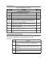
Table 5–1 Visual Alarm Codes.......................................................................................... 5-4
Table 5–2 Specifications for Solar panels....................................................................... 5-15
Table 5–3 RS-232 Field Wiring on XRC-195 Board........................................................ 5-25
Table 5–4 RS-485 Field Wiring on XRC-195 Board........................................................ 5-27
Table 5–5 RS-485 Terminations ..................................................................................... 5-27
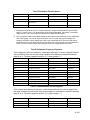
Table A–1 Discovery information for hardware drivers installed. .................................... A-64
Table A–2 Discovery PCU32 Ini Partnumbers. ............................................................... A-65
Table A–3 Discover Firmware number and revision of IO modules................................ A-65
vii
B
Bllaannkk P
Paaggee
viii
Introduction
About the Manual
This manual is written to provide an experienced flow meter technician with the
requirements necessary to install, setup and operate a Totalflow XSeries Remote
Controller System.
Organization
& Style
Each of the chapters in this manual presents information in an organized
and concise manner. Readers are able to look at the headings and get a
broad picture of the content without reading every word. Also, there are
overviews at the beginning of each chapter that provides you with an idea
of what is in the chapter, and how it fits into the overall manual.
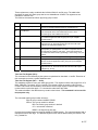
Highlights
This manual provides the following information:
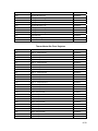
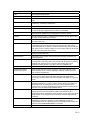
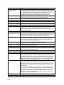
Chapter
Description
1) System Description
Provides a description of the Totalflow, XSeries
system components and specifications.
2) Installation
Includes unpacking and detailed procedures for
setup and installation.
3) XRC Startup
Provides you with a tutorial on how to get a
newly installed XRC system up and running.
4) Maintenance
Provides instructions on how to remove and
replace major modules.
5) Troubleshooting
Provides a description of the XRC front panel
error messages and provides a troubleshooting
chart on how to correct most problems.
Appendix A: Modbus
Register Table
Provides a listing of all valid Modbus Registers.
Appendix B: Definitions
& Acronyms
Provides quick access to the majority of terms
and abbreviations, as well as their definitions.
Appendix C: Drawings
Provides a place to put drawings that
accompany a unit.
ix
Getting Help
At Totalflow, we take pride in the on going support we provide our customers. When you
purchase a product, you receive documentation which should answer your questions;
however, Totalflow Technical Support provides you an 800 number as an added source of
information.
If you require assistance, call:
USA: (800) 442-3097
International: 001-918-338-4888
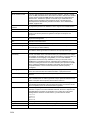
Before You
Call
•
•
•
•
•
Know your Totalflow’s model and serial number. Serial numbers can
be found on a plate located on each unit.
Be prepared to give the customer service representative a detailed
description of the problem.
Note any alarms or messages as they appear.
Prepare a written description of problem.
Know your software version, board and optional part numbers.
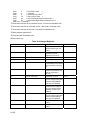
Key Symbols
The following symbols are used frequently in the manual. These are intended to catch your
eye and draw your attention to important information.
Intended to draw your attention to useful information or to clarify a
statement made earlier.
Intended to draw your attention to a fact that may be useful or helpful in
understanding a concept.
Intended to draw your attention to a statement that might keep you from
making a mistake, keep you from destroying equipment or parts, or keep
you from creating a situation that could cause personal injury if caution
is not used. Please refer to the “Safety Practices and Precaution”
section for additional information.
Intended to draw your attention to a statement regarding the likelihood of
personal injury or fatality that could result from improper access or
techniques used while working in hazardous locations. Please refer to
the “Safety Practices and Precaution” section for additional information.
x
Safety Practices and Precautions
This manual contains information and warnings which have to be followed by the user to
ensure safe operation and to retain the product in a safe condition. Installation, maintenance
and repairs should only be performed by a trained and qualified technician. Please refer to
Certification Drawings shipped with this unit for specific guidelines. Extra copies of the
certification drawings, referenced on the unit Name Tag, can be obtained, free of charge, by
contacting Totalflow Technical Support at the number listed in the “Getting Help” section.
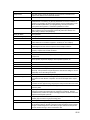
Safety
Guidelines
•
•
•
•
•
Safety First
DO NOT open the equipment to perform any adjustments,
measurements, maintenance, parts replacement or repairs until all
external power supplies have been disconnected.
Only a properly trained technician should work on any equipment with
power still applied.
When opening covers or removing parts, exercise extreme care "live
parts or connections can be exposed".
Installation and maintenance must be performed by person(s) qualified
for the type and area of installation according to National and Local
codes.
Capacitors in the equipment can still be charged even after the unit
has been disconnected from all power supplies.
Various statements in this manual identified as conditions or practices that
could result in equipment damage, personal injury or loss of life will be
highlighted using the following Icons.
Exercise caution while performing this task. Carelessness
could result in damage to the equipment, other property
and personal injury.
Stop. Do not proceed without first verifying that a
hazardous condition does not exist. This task may not be
undertaken until proper protection has been accomplished,
or the hazardous condition has been removed. Personal
injury or fatality could result. Examples of these warnings
include:
• Removal of enclosure cover(s) in a hazardous location
must follow guidelines stipulated in the Certification
Drawings shipped with this unit.
• If unit is installed or to be installed in a hazardous
location, technician must follow the guidelines
stipulated in the Certification Drawings shipped with
this unit.
• Access to unit via PCCU cable in a hazardous location
must follow guidelines stipulated in the Certification
Drawings shipped with this unit.
• Connecting or disconnecting equipment in a
hazardous location for installation or maintenance of
electric components must follow guidelines stipulated
in the Certification Drawings shipped with this unit.
Continued on Next Page
xi
Safety Practices and Precautions, Cont.
DANGER indicates a personal injury hazard immediately accessible as
one reads the markings.
CAUTION indicates a personal injury hazard not immediately accessible
as one reads the markings, or a hazard to property, including the
equipment itself.
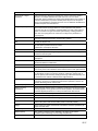
Equipment
Markings
Protective ground (earth) terminal
Grounding
the Product
If a grounding conductor is required, it should be connected to the
grounding terminal before any other connections are made.
Operating
Voltage
Before switching on the power, check that the operating voltage listed on
the equipment agrees with the power being connected to the equipment.
Danger From
Loss of
Ground
A grounding conductor may or may not be required depending on the
hazardous classification. If required, any interruption of the grounding
conductor inside or outside the equipment or loose connection of the
grounding conductor can result in a dangerous unit. Intentional
interruption of the grounding conductor is not permitted.
Safe
Equipment
If it is determined that the equipment cannot be operated safety, it should
be taken out of operation and secured against unintentional usage.
Fuse
Replacement
Fuses used on XSeries Model electronic boards are surface mount and
field repair should not be attempted. Most fuses automatically reset
themselves, but if a know problem exists, the board should be sent in for
repair or replacement.
xii
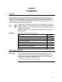
Chapter 1
System Description
Overview
This Chapter introduces you to the Totalflow® XSeries Remote Controllers (XRC). The
XSeries are low power, microprocessor based units designed to meet a wide range of
automation, monitor, control, alarming and measurement applications. Four models are
available: Models XRC6490, 6790, 6890 and 6990.
The letters XRC stand for Extendable Remote Controller. As their name implies, they are
expandable to meet your needs, while maintaining backward compatibility with legacy
Totalflow systems.
Each model is packaged in an enclosure that can accommodate the Main Electronic Board
(XRC-195 Board), Liquid Crystal Display, a variety of batteries, remote communication
device (except 6990), and additional I/O Modules. The XRC6490 can accommodate up to
3 I/O Modules, the XRC6790 can accommodate up to 6 I/O Modules, the XRC6890 can
accommodate up to 14 I/O Modules and Rack Mount XRC6990 can accommodate up to 6
I/O modules per Main Electronic Board.
The XRC is powered by a battery system, which can be charged using; either solar panel,
24Vdc or 120/240 VAC chargers. It is optimized for extremely low power consumption and
is primarily designed for remote operation in harsh environments.
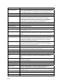
Highlights
This Chapter covers the following topics:
Topic
XSeries Remote Controller Hardware
Standard Enclosure
Rack Mount Enclosure
XRC General Specifications
XRC-195 Electronic Board Specifications
XSeries On-board Input/Output
Digital Output
Analog Inputs
Display Function
Functions of the XRC
Display Annunciators
Laptop Computer running PCCU32
FS/2 Handheld PCCU
Optional Equipment
Key Pad
Totalflow Input/Output Modules
See Page
1-2
1-4
1-7
1-8
1-9
1-11
1-13
1-14
1-15
1-16
1-17
1-20
1-20
1-21
1-21
1-24
Continued on Next Page
1-1
Overview, Cont.
Functionality
The XRC system has built-in, pre-engineered applications for data
collection, trending and long term data storage. The XRC can be used for
oil and gas production, transmission and distribution site monitoring and
control, water and waste system monitoring and control, etc.
This system can be programmed for advanced control or shutdown logic
using the IEC 61131 Control Language. An extensive applications library
is available from Totalflow Projects Engineering as needed, or new
application programs can be developed for you by Totalflow.
It is also possible for experienced IEC 61131 programmers in your
company, or other companies, to design application programs for any
XRC device.
XSeries Remote Controller Hardware
The Totalflow® XSeries Remote Controller (XRC) Models are housed in an aluminum
case. With the exception of the size of the cases all models use identical components.
These are the components of the XRC:
• Enclosure
• XRC-195 Board (Model 6990 may have up to two)
• Battery Compartment
• Communication Compartment
• Liquid Crystal Display (LCD) (Model 6990 may have up to two)
• Charger or Solar Panel
• Optional Modular I/O
• Optional Keypad (Model 6990 may have up to two)
XRC-195 Board
The XRC-195 board is mounted on the inside of the door. All XRC on
board input and output connections are made with snap-in connector
terminals mounted directly on the board. The board uses a low power
processor running at 11.0592 MHz with 512 K SRAM and 512 KPROM
and 32K E2PROM. Other circuitry processes the inputs from the on
board I/O and provides the interface to the LCD as well as the PCCU
and optional key pad. Remote communications are handled by the
RS232 and RS485 communication modules that plug directly into the
board. The following XRC-195 Board drawing shows all the major
functional parts and their locations when mounted.
Communication
Enclosure
A removable communications enclosure can be provided that has been
pre-drilled for mounting of many popular communications devices such
as radios, cellular phones, modems, etc. This feature is not available in
the XRC6990.
Continued on Next Page
1-2
XSeries Remote Controller Hardware, Cont.
Battery
Compartment
The XRC system houses an internal main battery.
• XRC6490: The battery sets in a central compartment directly
behind the removable battery plate.
• XRC6790: The battery sets in a central compartment directly
behind a hinged cover plate holding the DIN rail and installed
modular components.
• XRC6890: The battery sets on the floor of the main compartment
and houses the various optional battery packs that are available for
the XRC; from one 8 ampere hours up two 70 ampere hour
batteries.
• XRC6990: The 30 ampere hour battery sets on the floor of the
enclosure.
Solar Panel
The XRC is configurable for a 10-Watt, 20-Watt or 30-Watt solar panel.
The panel is designed for mounting on a 2-inch extension pipe above
the XRC, on top of or the side of a meter house. As the XRC6990 is not
designed for outside installations, Solar Panel chargers must be
configured to mount outside of the building.
Additional
Features
Additional features of the Totalflow System enabling its flexibility
include the following:
•
•
•
•
•
•
•
•
•
Programmable bi-level security system prevents unauthorized
communication and configuration of the XRC (See Chapter 3)
Internal crystal controlled clock providing a highly stable time base
for the system
Optional battery packs to extend operation for longer periods
without power
Three available charging sources
External solar panel (standard)
External AC power
External 24/12 VDC power
LCD (liquid crystal display) programmable to allow monitoring of
operations (for example, displays flow rate, volumes, etc.)
Rugged, aluminum, powder coated, NEMA 4X enclosure, lockable
to prevent internal access
Optional ability to allow rapid data collection over several
communication links.
Additional I/O for valve control, pressure, level monitoring, remote
communication, etc.
Optional Keypad
1-3
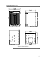
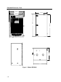
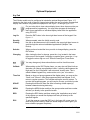
Standard Enclosure
The standard enclosure consists of hinged-door box in varying sizes for the XRC6490,
6790 and 6890 (see Figure 1–1 through Figure 1–3). The door provides a watertight,
corrosion resistant seal between the outside elements and the XRC components. It is
designed to meet Class I, Division 2, Groups C&D and is NEMA 4X rated. It is designed for
mounting in harsh environments (cold, hot, wet and salty). Opening the door’s latch(s)
allows access to electronics, battery, radio and modular components. This door may be
locked for security purposes.
(12.55)
(11.52)
(10.269)
(10.27)
(14.81)
X RC 6490
Figure 1–1 Model XRC6490
Continued on Next Page
1-4
Standard Enclosure, Cont.
X RC 6790
Figure 1–2 Model XRC6790
Continued on Next Page
1-5
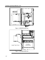
Standard Enclosure, Cont.
(20.09)
(15.52)
(18.70)
(15.52)
(28.00)
(28.81)
XRC 6890
(18.00)
Figure 1–3 Model XRC6890
1-6
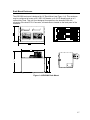
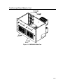
Rack Mount Enclosure
The XRC6990 enclosure is designed for 19” Rack Mount (see Figure 1–4). This enclosure
may be configured to house up to 2 XRC-195 boards, up to 2 LCD displays and up to 2
optional Key Pads. This unit is not designed for exposure to the elements. With the
exception of the local PCCU Connector, all terminals are located on the back panel of the
enclosure.
91
16.
Figure 1–4 XRC6990 Rack Mount
1-7
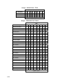
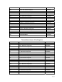
XRC General Specifications
Dimensions
Installed Depth
Enclosure
XRC Model
Width
Height
Depth
6490
11.52” (292.61mm)
14.81” (376.17mm)
10.27” (260.83mm)
6790
15.10” (383.54mm)
18.80” (477.52mm)
13.38” (339.85mm)
6890
20.09” (510.29mm)
28.91” (734.31mm)
15.52” (394.21mm)
6990
16.91” (429.51mm) 1
10.47” (265.93mm)
10.21” (259.33mm)2
XRC Model
Pipe Mounted
Direct Mounted
6490
12.75” (323.85mm)
11.00” (279.40mm)
6790
15.75” (400.05mm)
14.00” (355.60mm)
6890
18.01” (457.45mm)
16.26” (413.00mm)
XRC Model
Weight
(w/o battery)
Max
I/O Modules
Max
Battery Capacity
6490
8.86 lbs. (3.31k)
3
26 AH
6790
29.0 lbs. (13.17k)
6
42 AH
6890
45.5 lbs. (16.98k)
12
140 AH
6990
12.0 lbs. (5.44k)
14
30 AH
Humidity
0–95% Non-Condensing
Mounting
Wall, Pipe or Rack Mount
Operating Temp.
-40° F to 140° F (-40 to 60°C)
Certification (all
but 6990)
CSA/NRTL Class 1, Division 2, Groups C & D hazardous area
classification. (ATEX Zone 2 pending). XRC6990 is General Purpose
EMC
Requirements
EMMISSIONS:
IMMUNITY:
1
European Regions:
• EN55022 Class A Emissions (Radiated & Conducted)
North America Regions:
• CFR 47, Part 15, Subpart B, Class A, FCC Emissions
• ICES-003 Issue 2, Rev. 1, Class A ITE Emissions
European Regions:
• EN50082-1:98 Immunity
• EN61000-4-2:95, ESD, ± 8 kV Air, ± 4 kV Contact
• EN61000-4-3:95 RF Immunity, 10 V/m
• EN61000-4-4:95 EFT, 1 kV
• EN61000-5-5:95 Surge; 1 kV line to line, 2 kV line to
earth
• EN61000-4-6:95 Conducted Susceptibility, 3 Vrms
• EN610004-8:93 Power Frequency Magnetic Field 3
A/m
• EN610004-11:94 Voltage DIP and interrupt
Enclosure width does not include mounting rail. Total width is 19” (482.6mm)
2 Enclosure depth does not include TFIO Modules mounted. Depth with Modules: 14.72” (373.89mm)
1-8
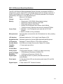
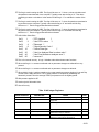
XRC-195 Electronic Board Specifications
The XRC-195 Electronic Board (extendable Remote Controller, part number 2100355) is
designed as a general- purpose RTU motherboard that mounts in all XSeries enclosures. It
has the same footprint as its counterpart, the XFC-195 Board (extendable Flow Computer
motherboard). See Figure 1–5 for XRC Board layout.
Power
Nominal 12 VDC Battery
Charger
Solar or 14-26 VDC
Memory
•
•
•
•
•
Comm. Ports
1 - dedicated – Local Configuration port used with our PCCU32
software
2 - RS232 or RS485 via Plug-In Modules
Microprocessor
High integration microcontroller with 20 bit address bus (1M), operating
at 11MHz
LCD Interface
Dedicated Interface for 2 X 24 Liquid Crystal Display (LCD)
Keypad Interface
Dedicated Interface for Optional ABB supplied Keypad Equipment
I/O Expansion
Dedicated I2C Serial I/O Bus for TFIO module expansion
Security Switch
On/Off Bi-level on-board Security (See Chapter 3 for details)
Time Bas
Stability
± 7.5 ppm (parts per million)
I/O Scan Rate
1 time per second
Analog Inputs
5 Single-ended Channels, 0–10VDC or 0–20ma current loop.
Analog to Digital
Resolution
•
•
Digital Inputs
4 -configurable as active or passive (Selectable de-bounce
enable/disable)
Pulse Inputs
2 of the above listed 4 DIs can be used as pulse inputs (DI1 and DI2)
(up to 20 KHz)
Digital Outputs
4 -Open channel FET Transistor Switches
Data stored in 512K SRAM. (lithium battery backup)
Applications programs stored in 512K Flash.
Flash loader stored in 512K PROM
Registry and Configuration files stored in 32K E2PROM
Transducer factory calibration data stored in separate E2PROM
18 Bit Maximum Resolution (0.00038% FS)
18 Bit Nominal Resolution (0.0015% FS)
Continued on Next Page
1-9
XRC-195 Board Specifications, Cont.
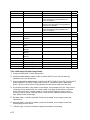
Figure 1–5 Complete View XRC-195 Board
Continued on Next Page
1-10
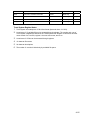
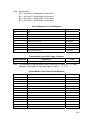
XRC-195 Board Specifications, Cont.
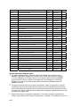
Table 1–1 XRC Board Component Descriptions
ID Number
Description
ID Number
Description
1
SRAM (Lithium backed)
15
A-PI/DI/DO Connectors
2
Flash Program Memory
16
B- PI/DI/DO Connectors
3
Prom Loader/Utilities Memory
17
Remote Comm 1: Connectors
4
Factory Maintenance Interface
18
Remote Comm 2: Connectors
5
Keypad Connector
19
Remote Comm 2: RS-485 Term. Jumper
6
Security Switch
20
Remote Comm 2: Module Plug-in
7
Lithium Battery
21
Remote Comm 1: RS-485 Term. Jumper
8
Battery Cover
22
Remote Comm 1: Module Plug-in
9
Battery Mounting Bracket
23
External Charger Connector
10
Memory Backup Enable/Disable
24
Battery Connection
11
Analog Input Connectors
25
I/O Module Interface
12
Analog Input Selection Jumper
26
LCD Display Interface
13
Aux. Power Output Connectors
27
PCCU Interface
14
DeBounce Enable/Disable
28
SDRIVE: 32K E2Prom
29
Contrast Potentiometer
XSeries On-board Input/Output
Totalflow's XRC features the base I/O listed below:
• 5 User A/I's
• 4 User D/O's
• 4 User D/I’s (2 may be used as High Speed P/I’s (D/I 1 and D/I 2))
• 2 RS232 or 485 Comm Ports
• 1 Dedicated Local Communication Port
• Interface for TFIO Modules
The Main Electronic Board (XRC-195 Board) is an enhanced replacement for previous
versions of the RTU Main Electronic Board. In the next few pages, you will see the
specifications for Digital/Pulse Input, Digital Output and Analog Input. To see a complete
overview of the XRC-195 Board, see Figure 1–5.
Comm. Ports
You have the ability to program up to two on-board communication ports
on the XRC-195 Board. Normally COMM 0 is the local port required for
reading the XRC with a laptop computer running PCCU32. COMM 1 and
COMM 2 can be configured for any combination of RS 232 or RS 485.
See Figure 1–5 for On-Board Communication Ports.
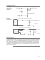
1-11
Digital Input
The Totalflow XRC provides 4 digital inputs(2 of which may be used as high speed pulse
inputs) as a means to monitor inputs from external equipment with the XRC. See Figure 1–
5, Item #s 15 & 16.
When connecting or disconnecting any wires to the XRC-195 Board, you
should remove all power sources and make sure that you are grounded
properly.
Digital Inputs
The Digital Input reads an external contact. Below you will find the
electrical and input specifications as well as information on enabling or
disabling DeBounce.
Electrical
Specification
(each point):
•
•
•
•
•
•
Input
Specification
•
•
•
•
•
DeBounce
Open circuit voltage: 5VDC (Internally pulled up to 5VDC Nom.)
Short circuit leakage current: -395uA typical.
Input capacitance: 0.1 ufd typical.
Maximum allowable voltage range on input -0.5VDC to 15VDC.
Maximum frequency input 100Hz @ 50% duty cycle with de-bounce
enabled.
Maximum frequency input 10KHz @ 50% duty cycle with de-bounce
disabled.
Dry Contact, Open Collector or Active Voltage.
Minimum contact resistance to activate input 1000Ω.
Maximum voltage to deactivate the input: 3.1V (referenced to GND
terminal.)
Minimum voltage to activate the input: 0.5V (referenced to GND
terminal.)
Conductor pairs must be shielded to prevent spurious signals.
The XRC-195 Board includes Jumper Pins to enable or disable
debounce. See Figure 1–5, Item# 14 for the Jumpers. The inclusion of the
Debounce capacitor when enabled allows the unit to ignore noise when
manual switches are set. When disabled, the high speed pulses are
received exactly as sent. If input is received as a solid state signal, then
debounce is not needed, it should be disabled.
Typical Point
Schematic
+5
10K
SIG
1K
INPUT SENSE
.1UF
DEBOUNCE SELECT
GND
Continued on Next Page
1-12
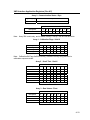
Digital Input, Cont.
Example
Connections
+5
POINT CONNECTIONS
SIG
SIG
SIG
SIG
10K
INPUT SENSE
1K
.1UF
OPTO
COUPLER
NPN
SWITCH
DEBOUNCE SELECT
GND
OR
GND
GND
OR
GND
TYPICAL VOLTAGE INPUT FIELD
FIELD DEVICE
+5
10K
15 VDC MAX.
SIGNAL
OUTPUT
3.1 VDC
SIG
SIG
0.5 VDC
INPUT SENSE
1K
.1UF
-0.5 VDC MIN.
DEBOUNCE SELECT
COMMON (GND)
GND
GND
Digital Output
The Totalflow XRC provides 4 digital (12Vdc) outputs as a means to control external
equipment with the XRC. See Figure 1–5, Item Nos. 15 & 16.
When connecting or disconnecting any wires to the XRC-195 Board, you
should remove all power sources and make sure that you are grounded
properly.
Digital Outputs
If the digital output is used in conjunction with a measurement device;
AGA3, AGA7 or Liquid Measurement, the following outputs can be
triggered when the following conditions occur:
•
Differential pressure over high limit
•
Volume Set Point
•
Differential Pressure under low
limit
•
Flowing Temperature Low
•
Static Pressure over high limit
•
Flowing Temperature High
•
Static Pressure under low limit
•
Flow Rate Low
•
Low Charger voltage
•
Flow Rate High
•
Remote Sense is ON
•
Trip on Digital Input
Other Applications are:
• Custom programmable by Totalflow or user programmable with IEC
61131 programming language.
Continued on Next Page
1-13
Digital Output, Cont.
Electrical
Specification
(each point):
Input
Specification
•
•
•
•
•
•
•
•
Typical Point
Schematic
Open circuit voltage: 0VDC
Short circuit leakage current: 0uA typical.
Output capacitance: 1000pF typical.
Maximum allowable voltage range on output -0.5VDC to 26.5VDC.
Open Drain FET type.
"ON" Resistance: 0.1Ω Typical (Including PTC fuse resistance).
Maximum pulse current: 3A for 5 seconds.
Maximum continuous sink current: 2A.
SIG
2.5A
24V
OUTPUT CONTROL
GND
Example
Connections
TYPICAL SINK OUTPUT FIELD WIRING
BATTERY (+) OR POWER
POSITIVE TERMINAL (24 VDC MAX)
SOURCE
LOAD
SIG
SIG
2.5A
24V
OUTPUT CONTROL
BATTERY (-) OR POWER
COMMON OR GND SOURCE
TERMINAL
GND
GND
Analog Inputs
Electrical
Specification
(each point):
•
•
•
•
•
•
Voltage Mode:
Current Mode:
Maximum Voltage mode input before soft over-range:
Maximum allowable continuous input current:
Typical Input Impedance Voltage Mode:
Typical Input Impedance Current Mode:
0-10V
0-20mA
10.7V
22.8mA
91.24K Ohms
249.3 Ohms
Continued on Next Page
1-14
Analog Inputs, Cont.
Typical Point
Schematic
0-10V To ADC
SIG (+)
255 Ohm
Resistor
24V
Input Mode Select
GND
Example
Connections
TYPICAL VOLTAGE ANALOG INPUT FIELD WIRING
SIGNAL
OUTPUT
SIG (+)
0-10V To ADC
SIG (+)
FIELD
DEVICE
24V
Voltage Mode
COMMON (GND)
GND
GND
TYPICAL 2 WIRE 4--20mA FIELD DEVICE WIRING
POWER SOURCE POS. TERM.
(+) XMTR(-)
SIG
0-10V To ADC
SIG (+)
FIELD DEVICE
24V
POWER SOURCE COMMON
OR GND TERMINAL
255 Ohm
Resistor
Current Mode
GND
GND
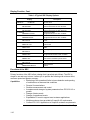
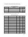
Display Function
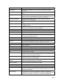
During operation of the XRC, the front panel LCD continuously scrolls through the operating
parameters. Table 1–1 shows typical displayed parameters when used with an AGA-3 flow
tube, however any parameter with a Register Address can be displayed. The duration that
the parameter is displayed can vary from 1 to 255 seconds (default is 5 seconds); a setting
of 0 seconds will set any display to off. See "Program Display" in Chapter 3 (and PCCU32
help files) for more details.
Continued on Next Page
1-15
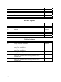
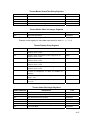
Display Function, Cont.
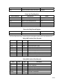
Table 1–2 Typical XRC Display Options
Display
DATE/TIME
MM/DD/YY
HH:MM:SS
YEST DP LO
NN PERCENT
YEST DP HI
NN PERCENT
FLOWRATE
NNNNNN.N SCF/HR
ACCUM VOL
NNNNNN.NN MCF
BATTERY
NN.N VOLTS
DIFF PRESS
NNN.N IN. H2O
PRESSURE
NNN.N PSIA
FLOW TEMP
NN.N DEG. F
YEST VOL
NNNN.N MCF
PERIOD VOL
NNNN.N SCF
CHARGER
NN.N VOLTS
Orifice Dia.
NNNN.NNNN INCHES
Description
Current Date and Time
24 hour clock
Yesterday’s Percent DP Low Limit
Percent time below DP Low Set Point
Yesterday’s Percent DP High Limit
Percent time below DP High Set Point
Current Flow Rate
Programmable SCF or MCF or MMCF
Total Accumulated Volume
Programmable SCF or MCF or MMCF
Battery Voltage
Volts
Differential Pressure
Inches H2O
Static Pressure Absolute
PSIA
Flowing Temperature
°F
Yesterday’s Volume
Programmable SCFM or MCF or MMCF
Previous Period Volume
Last volume calculation period volume
Charger Voltage
Orifice Diamter
Inches
Functions of the XRC
Primary functions of the XRC reflect a design that is practical and efficient. The XRC is
simple to use and easy to learn. It allows you to perform the following with minimum effort,
maximum speed and greater accuracy.
Capabilities
•
•
•
•
•
•
•
•
•
Monitoring of the operational limits to insure detection and reporting
of malfunctions or abnormal site conditions
Remote Communications
Realtime measurement and control
Acceptance and storage of system parameters from PCCU32 4.3 or
greater
Storage of data records
Storage of operational events
Expandable I/O count to support most customer applications
Multiple enclosure sizes provided to fit specific I/O requirements
Custom IEC 61131 Applications to fit specific customer requirements
Continued on Next Page
1-16
Functions of the XRC, Cont.
Applications
•
•
•
•
•
•
•
•
•
•
•
•
•
•
•
•
•
•
XRC Display
Function
During the operation of the XRC the front panel LCD continuously scrolls
through the operating parameters. Your system will come with a group of
standard system displays, however any parameter with a Register
Address can be displayed.
See "Program Display" in Chapter 3 for more details.
AGA3 orifice meter run (an external transducer required)
ISO 5167 orifice meter run (an external transducer required)
V-Cone meter run (an external transducer required)
AGA7 rotary/turbine meter run
Wedge meter (liquid and gas) (an external transducer required)
CO2 (NIST 14) (an external transducer required)
Real-time Data Logger (Trending)
Valve Control (feedback controller)
RAMS (Alarming, Exception reporting)
Operators (simple math/logic functions)
IEC 61131 (complex math/logic)
Selectable Units (user selectable engineering units)
Display / Keypad Handler
I/O Subsystem
Tank Level application
Therms Master application
Therms Slave application
Multiple protocols (Totalflow proprietary low power, Modbus Slave
(RTU/ASCII), Modbus Master (RTU/ASCII), LevelMaster, BTU
8000/8001, Enron Modbus, Square D, MotorSaver, ABB 2010T
Multivariable, Altronics and others
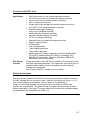
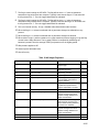
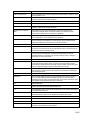
Display Annunciators
One of the primary functions of the XRC is for monitoring operational conditions; therefore,
the XRC indicates when an unusual or “alarm” condition is occurring, see Figure 1–6. For
how to use the display to troubleshoot, refer to Chapter 5; Troubleshooting.
Using new technology adaptable for multi-tube devices, the status and alarm code
locations are programmable. This allows the user to program each annunciator to reflect
different application or tube types. The single tube device will come with a standard display
pre-programmed, but changeable (see Table 1–2).
Continued on Next Page
1-17
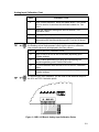
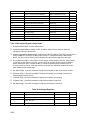
Status and Alarms Description, Cont.
Figure 1–6 Liquid Crystal Display and Indicators
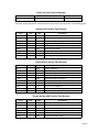
Table 1–3 Status and Alarm Description
Indicator
Description
I/O Sub-System
L
L
L
C
Low Lithium Battery Alarm: When LL (low lithium) is displayed, lithium
battery voltage is below 2.5 Vdc. A new lithium battery measures
approximately 3.6 Vdc.
Low Charger. Displayed if XRC battery charging voltage is (+)0.4 Vdc
or is less than or equal to battery voltage.
Display Application
1
A number represents the Display Group number currently being
displayed.
↑
The displayed item’s value is above the Data High Limit value
specified on the display Item Setup screen.
↓
The displayed item’s value is below the Data Low Limit value specified
on the display Item Setup screen.
Communications Protocols
→
Transmitting Data:
←
Receiving Data:
!
Nak. Negative Acknowledgement w/packet list.
+
Ack. Positive Acknowledge of receipt of request.
Waiting for Ack. Waiting for response after transmission.
ID Recognized.
Table Continued on Next Page
1-18
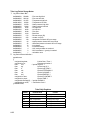
Status and Alarms Description, Cont.
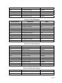
Table 1–2 Status and Alarm Description, Cont.
Indicator
Description
Communications Protocols, Cont.
Listen Cycle. Flashes if this remote port is active and running
Totalflow Remote Protocol. Flashes in sync with listening cycle that
occurs at 1, 2 or 4 second intervals.
M
MODBUS ASCII: Modbus ASCII protocol is selected for the port
assigned to this annunciator.
m
MODBUS RTU: Modbus RTU protocol is selected for the port
assigned to this annunciator.
R
LevelMaster Protocol. LevelMaster protocol is selected for the port
assigned to this annunciator.
L
Local Protocol. Displayed when PCCU part is active and running
TOTALFLOW Local Protocol.
¥
Packet Protocol. The Totalflow Packet Protocol selected on this port.
Valve Control
V
Displayed when Valve Control option Enabled.
⎡
Valve Control option installed. Valve is in full open position.
⎦
Valve Control option installed. Valve is in full closed position.
↑
Valve Control option installed. Valve is opening (open signal is being
sent to valve actuator).
↓
Valve Control option installed. Valve is closing. (close signal is being
sent to valve actuator).
Ö
Valve Control option installed. Valve controller override conditions met
(DP/SP override set point or Low Battery).
L
L
Valve Control option installed. Local Lock-out is initiated.
Table Continued on Next Page
1-19
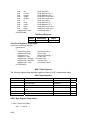
Status and Alarms Description, Cont.
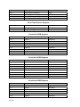
Table 1–2 Status and Alarm Description, Cont.
Indicator
Description
Measurement Application
BF
Back Flow Condition. Visible only when DP variable displayed.
Z
Zero Flow Condition: Visible only when Flow Rate displayed.
H
Hold. Displayed when HOLD flag is active. Also displayed when
transmitters are being calibrated or A to D Converter cannot be read.
A
Alarm Condition. Need to view alarm. You may need to compare
application limits to current values to determine where the alarm
condition is present.
AD
A to D Failure. Displayed if A to D Converter Differential Pressure,
Absolute Static Pressure or temperature readings exceed maximum
counts or are less than minimum counts.
Laptop Computer running PCCU32
PCCU32 Software running in a laptop Windows environment offers you the most
capabilities for programming the XRC. Many of the new features designed into the XRC
cannot be accessed by the FS/2 due to it’s limited capabilities. The Windows environment
features user friendly help files and easy to follow menus. Having help files readily
accessible to the user is comparable to having a virtual teacher on location. Easy to follow
menus and icons, step the user through many required choices.
The laptop computer connects via the cable directly to the connector on the side of the
XRC. Once this physical connection has been made, you may begin communicating
through the software.
Also see Technical Bulletin #44 for “Terminal Mode” Connection.
FS/2 Handheld PCCU
The FS/2 Portable Calibration & Collection Unit (PCCU) is a hand held device running the
DOS version of PCCU. This equipment allows the user to perform only the most basic of
operations and program the minimal features of the XRC. Because the device functions in
the DOS environment, help files, icons and drop down menus are not available. Therefore
this device is more limited.
The FS/2 PCCU connects via the cable directly to the connector on the side of the XRC.
Once this physical connection has been made, you may begin communication with the
XRC through the program.
1-20
Optional Equipment
Key Pad
The XSeries models may be configured to include the optional Keypad (see Figure 1–7)
located on the front cover of the unit. Keypad entry allows the user to monitor programmed
display items without using additional equipment. See Figure 1–8 through Figure 1–10.
For you to be able to view various display items, those items must be preprogrammed for keypad entry. You may either program all the display
items for an application or individual display items within the application
using PCCU32.
Log On
Press the ENT button in the lower right hand corner of the keypad. See
Figure 1–7.
Security
When prompted, enter the 4-digit security code.
Viewing
Use the up and down arrow keys located in the upper right hand corner to
scroll through the various instantiated applications (Multiple Tube
Device).
Selectin
When you have located the item you wish to change/display, press the
ENT button.
Changing
After viewing the item for change, press the = key located in the lower
right corner of the keypad. If entering a negative figure, press the +/- key
to toggle the minus sign on or off. Enter the new figure. Press Enter.
You may change only those values that are not live from this screen.
Validate
When setting up the XRC Display items, you may also set Data Limits so
that when you change a programmed value, it must be valid between the
High and Low Limit, otherwise it will return and “invalid” code. This is
called Validate Keypad Entry, and must be set to “yes” to be active.
Time Out
Based on how you have programmed the display setup, you may set the
“Scroll Lock Timeout”. After the programmed time has elapsed, it will
return to regular operation. This includes exiting the security system. To
re-enter the keypad program, you will need to re-enter your security code.
SPACE
Pressing this button will have the effect of leaving a blank space(s)
between characters during data entry.
MENU
Pressing the MENU button and then the group number and item number
will take you directly to the specified screen.
REG
Pressing the REG button and then entering the “application.array.index”
of the register you would like displayed will take you directly to the
specified register.
ESC
To exit the program, press the ESC key in the lower left corner once for
each level you are viewing. When the screen begins to scroll again, you
have exited the program completely.
Continued on Next Page
1-21
Key Pad, Cont.
Figure 1–7 Optional Keypad (P/N 2100652-xxx)
10.60
XRC 6490
Figure 1–8 XRC6490 with Optional Key Pad
Continued on Next Page
1-22
Key Pad, Cont.
13.72
XRC 6790
Figure 1–9 XRC6790 With Optional Keypad
15.85
XRC 6890
Figure 1–10 XRC6890 With Optional Keypad
Continued on Next Page
1-23
Key Pad, Cont.
SIDE VIEW WITH KEYPAD
FRONT VIEW WITH KEYPAD
Figure 1–11 XRC6990 with Dual Keypads
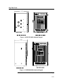
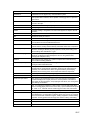
Totalflow Input/Output Modules
In addition to Totalflow’s enhanced on-board input/output capabilities, the hardware
functionality of the XSeries can be extended in a flexible and friendly way by adding
modular I/O as needed (see Figure 1–12). Totalflow I/O (TFIO) modules are designed to
accommodate low power, harsh environment and economical cost requirements. The
system automatically recognizes the module types and configures the I/O Scanner
subsystem accordingly.
The modules are interfaced to the XRC-195 Board by an I2C bus. On top of this bus,
Totalflow has implemented an efficient I/O protocol to exchange information between the
modules and the XRC-195 Board. The bus operates in a master/slave mode, with the Main
Board acting as master.
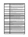
The XRC6490 (as shown in Figure 1–13) systems support up to 3 modules. For example, 3
analog input modules can be connected to the I2C bus. Since each module supports 8
analog inputs, then a total of 24 analog inputs can be added to the I2C bus. The XRC6790
(as shown in Figure 1–14) systems support up to 6 modules. The XRC6890 (see Figure 1–
15) supports upto 14 and XRC6990 (see Figure 1–16) support up to 6 per XRC Board.
The I/O module hardware is packaged in DIN mount enclosures that employ Phoenix
contact technology for field wiring. The modules also interconnect with each other to
provide the necessary power and interface signals along their bus. Installation consists of
snapping the Phoenix connector onto the DIN rail and moving the module into position
directly beside and snapped to the next module. Likewise, in removing a module, it must
first be separated from the module on either side, then removed from the DIN rail.
For additional information, please refer to the TFIO Module User’s Manual (Part
No.2101226-001).
Continued on Next Page
1-24
Totalflow Input/Output Modules, Cont.
Figure 1–12 TFIO Module Housing
Figure 1–13 XRC6490 Inside View
Continued on Next Page
1-25
Totalflow Input/Output Modules, Cont.
Figure 1–14 XRC6790 Inside View
~
~
Inside Front Door
Battery
Compartment
Figure 1–15 XRC6890 Inside View
Continued on Next Page
1-26
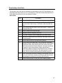
Totalflow Input/Output Modules, Cont.
Figure 1–16 XRC6990 Inside View
1-27
B
Bllaannkk P
Paaggee
1-28
Chapter 2
Installation
Overview
This Chapter provides you with the information for installation and setup. By the time you
finish this Chapter you will have the XRC unpacked, installed, field wired and ready for
operation. For safe and trouble free installation follow all instructions and advisories. Due to
is configuration, the XRC6990 Installation Instructions and it’s optional equipment are
grouped together near the end of this Chapter.
Read through this Chapter before you begin the installation, to plan your
installation. Also before you begin, refer to the wiring diagrams delivered
with the new XRC. You may store these in the back of this manual under
the tab Wiring Diagrams.
Installation procedures, presented within this Chapter, are applicable to
all XRC Models.
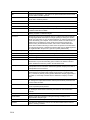
Highlights
This Chapter covers the following topics:
Topic
Unpacking & Inspection
Pipe Saddle Mount Installation
Wall Mount Installation
Battery Pack Installation
Solar Panel Installation
AC Charging Unit Installation
XRC6990 Rack Mount Installation
XRC Communication, Jumper Settings and Field Wiring
See Page
2-1
2-2
2-6
2-8
2-10
2-12
2-15
2-17
Unpacking & Inspection
Unpacking
The XRC is shipped in a specially designed shipping carton which
contains the unit, parts list and wiring and interconnect diagrams. The
Solar Panel, mounting brackets and the Battery Pack with applicable
hardware are shipped in a separate carton.
Carefully remove the items from each carton.
Continued on Next Page
2-1
Unpacking & Inspection, Cont.
Inspection
•
•
•
•
•
Damaged
Components
Inspect the shipping carton for damage. If the shipping carton is
damaged, keep it until the contents have been inspected for
damage.
Inspect the unit exterior for dents, chipped paint, etc.
Inspect the LCD window for breakage.
Open the housing by first removing the bolt and releasing the
latch/latches.
Visually inspect the Digital PC Board, cables, and connectors for
damage.
If any components has been damaged or if there are noticeable defects,
notify your Totalflow representative. Keep all shipping materials for the
carrier's inspection. Totalflow will arrange for immediate repair or
replacement; see 'Getting Help', page x.
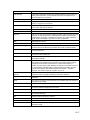
Pipe Saddle Mount Installation
If you are installing the unit directly to the meter run use this procedure. Before you begin,
review the procedure and the materials required for installation.
Materials
Supplied
•
Material Not
Supplied
Optional equipment may be ordered from Totalflow:
• One pipe Saddle
• One 2” pipe of suitable length
XRC mounting bracket and hardware
Instructions
Step
Procedure
1.
Position pipe saddle on meter run (see Figure 2–1). Select a
location that allows easy user access and is close to equipment.
2.
Temporarily attach Saddle on meter run pipe using U-bolt and
associated hardware, do not tighten.
3.
Screw 2” mounting pipe into Saddle. Place level against pipe
and vertically align. Adjust pipe, mounted in saddle, until vertical
alignment is achieved.
4.
After vertical alignment, securely tighten 2” pipe in Saddle then
securely tighten Saddle mounting bolts. Be certain pipe is
securely installed in Saddle.
Continued on Next Page
2-2
Pipe Saddle Mount Installation, Cont.
2" x 40"
Mounting Pipe
Saddle
Meter Run
"U" Mounting
Bolt
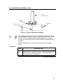
Figure 2–1 Typical Pipe Saddle Installation
The following procedures are to be followed when installing an XRC on
2” mounting pipe as shown in Figure 2–2 through Figure 2–4. To install
the XRC, it is recommended that two people perform the installation.
One to hold unit in position and the other to install and tighten mounting
brackets.
Method of installation must be consistent with customers company
policy.
Instructions
Step
Procedure, Cont.
5.
Position the XRC in position on the 2” mounting pipe and secure
in place with two U-bolts, flat washers, lock washers and two
9/16” bolts as shown in Figure 2–5.
Continued on Next Page
2-3
Pipe Saddle Mount Installation, Cont.
XRC 6490
Figure 2–2 Model XRC6490, Pipe Mounted
X RC 6790
2.00 PIPE (2.38 O.D.)
Figure 2–3 Model XRC6790, Pipe Mounted
Continued on Next Page
2-4
Pipe Saddle Mount Installation, Cont.
(2.83)
(16.82)
(.60)
(4X Ø.437)
(31.20)
(30.00)
XRC 6890
2.00 PIPE (2.38 O.D.)
Figure 2–4 Model XRC6890, Pipe Mounted
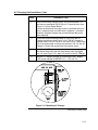
Flat and lock washers
with nut
U - Bolt
2 " Mounting Pipe
Figure 2–5 XRC Pipe Mounting
2-5
Wall Mount Installation
If you are installing to a wall near the meter run or inside a meter shed use this procedure.
Before you begin, review the procedure and the materials required for installation. Refer to
outline drawing for mounting dimensions requirements.
• Two U-bolts w/ fastening hardware
Optionally
• Enclosure mounting brackets
Supplied
Materials
• Four 1/4” machine bolts
Material Not
• #10 screws
Supplied
Caution
If the XRC is to be wall mounted, the wall itself should have sufficient
strength to support the hanging weight of the unit.
There should be no obstruction(s) that would prevent the XRC door from
being opened to access interior installed components or to interfere with
installation of the solar panel or other charging power sources.
Instructions
Step
Procedure
1.
Refer to Figure 2–6 through Figure 2–8 Outline Drawings, drill
mounting holes in wall supports.
2.
Install mounting brackets on back of XRC as shown.
3.
Lift and align XRC wall mounting brackets with mounting holes
drilled in wall.
4.
Insert 1/4” diameter machine bolts through XRC mounting
brackets into wall. Securely tighten all bolts to secure unit to
wall.
Continued on Next Page
2-6
Wall Mount Installation, Cont.
(2.83)
4X Ø.437
(11.00)
(.60)
(17.20)
(16.00)
XRC 6490
(.75)
Figure 2–6 Model XRC6490, Wall Mounted
X RC 6790
Figure 2–7 Model XRC6790, Wall Mounted
Continued on Next Page
2-7
Wall Mount Installation, Cont.
(2.83)
(4X Ø.437)
(.60)
(16.26)
(30.00)
(31.20)
XRC 6890
(.75)
Figure 2–8 Model XRC6890, Wall Mounted
Battery Pack Installation
A battery pack provides the XRC with it’s operating power. The battery is packed and
shipped separately. Before installation, inspect power cables, where they terminate on
battery pack, and connector for breakage.
Installation
In the following procedure, the common name for a component, its
jumper number if available (Abbreviated J) or part is followed by a
number in parentheses. For a complete overview of the XRC-195 Board,
see Figure 1–5.
Battery pack is mounted behind the removable metal battery plate cover.
The plate is adjustable for various size batteries.
Continued on Next Page
2-8
Battery Pack Installation, Cont.
Instructions
Step
Procedure
1.
Insert battery pack into lower compartment. Insert battery
pack with its long dimension facing outward.
2.
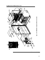
Connect battery pack connector to Digital Board Battery
Connection J16 connector (see Figure 2–9), located in upper
right corner of Board.
3.
Observe LCD, the display should be on and scrolling through
the startup diagnostics sequence.
Figure 2–9 XRC-195 Board Battery and Charger Input Connections
2-9
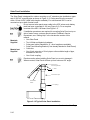
Solar Panel Installation
The Solar Panel is designed for outdoor mounting on a 2” extension pipe installed on upper
end of XRC 40” mounting pipe as shown in Figure 2–10. Solar panel must be mounted
within 12 feet of XRC (other cable lengths available). For wall mounted XRC it can be
mounted on top or side of meter house.
Do not connect solar panel power cable to the XRC unless main battery
pack has been connected to J16 (see Figure 2–9). For a complete
overview of the XRC-195 board, see Figure 1–5.
If installation procedures are required for mounting Solar Panel on top or
side of meter house, customer should contact Totalflow's Service
Department; see “Getting Help” in the Introduction section of this
manual.
Materials
Supplied
Material not
Supplied
•
•
•
•
•
•
•
One Solar Panel
Two U-Bolts and fastening hardware
Solar panel cable (Standard is 12’, other lengths are available)
Solar Panel Mounting Bracket (if not already attached to Solar Panel)
Cable ties
One 9-inch extension of 2-inch pipe or other suitable length of pipe,
threaded on one end.
One 2-inch coupling.
Exercise caution when installing Solar Panel, so as not to damage it.
When mounted, Solar Panel will face up from horizon at 50° angle.
Solar Panel
Mounting Bracket
U - Bolts
2 " Extension Pipe
Solar Panel
Cable
2 " Coupling
Figure 2–10 Typical Solar Panel Installation
Continued on Next Page
2-10
Solar Panel Installation, Cont.
Procedure
Our standard solar panel must be mounted within 12 feet of XRC. For
Solar Panel mounting, the following materials are required.
In the following procedure, the common name for a component, its
jumper number if available (Abbreviated J) or part is followed by a
number in parentheses. For a complete overview of the XRC-195 board,
see Figure 1–5.
Instructions
Step
Procedure
1.
Attach 2” pipe coupling to top end of XRC 40” mounting pipe.
Securely tighten.
2.
Install 2” pipe extension into coupling and securely tighten.
3.
Before installation of the panel, check solar panel using digital
voltmeter to verify polarity and output voltage. Voltage will
vary depending on amount of sun, angle to sun, etc
4.
Install Solar Panel on mounting bracket, if required, with
provided hardware. Install Solar Panel Cable if required.
DO NOT connect other end of Solar Panel Cable to XRC until instructed
to do so.
5.
Attach Solar Panel mounting plate to top end of 2” extension
pipe with U-bolts and associated mounting hardware. Do not
tighten U-bolts until Solar Panel has been correctly orientated.
6.
For northern hemispheres, position Solar Panel facing south.
For southern hemispheres, position Solar Panel facing north.
For optimum charging, solar panel should not be in shadows
for the majority of the day. Panel should be kept clean for
maximum charging.
7.
Remove CHGR Input terminal block (J17) from Digital Board.
Insert Solar Panel power cable through an access hole on
side of case. Allow enough power cable for field wiring to
CHGR Input +/- terminations on J17.
8.
Before making connections to terminal block, trim wire ends
back 1/4”. Loosen terminal block securing screws, insert wire
then retighten. Connect Solar Panel (+) lead to (+) terminal
and (-) wire to (-) terminal. Verify main battery pack is
connected and then reinstall terminal block with wires
attached.
9.
Following connection of Solar Panel power cable, secure
cable to 2’ extension pipe and mounting pipe cable with plastic
tie-wraps provided.
2-11
AC Charging Unit Installation
The AC Power Charging Unit maintains a constant voltage charge on installed battery pack.
There are many different types and styles. Each unit will come with wiring instructions.
Generally, you should follow the steps listed below.
Materials
Supplied
Materials Not
Supplied
The following hardware is required to mount the AC power charging unit
to XRC.
• AC Charging Unit
• Coupling nipple
• Plastic cable ties
• AC wiring, conduit (rigid or flexible)
To maintain system certification, all wiring must comply with NEC 501
code and applicable ABB certification drawings.
To prevent injury only a licensed electrician should install AC power
wiring to customer supplied primary AC power source.
Installation
In the following procedure, the common name for a component, its
jumper number if available (Abbreviated J) or part is followed by a
number in parentheses. For a complete overview of the XRC-195 board,
see Figure 1–5.
Instructions
Step
Procedure
1.
The AC Charging Unit is shipped separately. When unit is
received, unpack and inspect all components for evidence of
damage. Report damage to shipping carrier and to Totalflow's
Service Department.
2.
Remove one of the plugs from the side of XRC so that AC
charging unit can be mounted without obstruction.
3.
Feed AC Charger DC power lines into XRC. Allow enough
cable to extend into unit for connection to CHGR Input +/terminals J17 (see Figure 2–9) on the Main Electronic Board.
4.
Connect AC Battery Pack Charger to XRC using supplied
sealing ring and nut (see Figure 2–11).
To prevent moisture from entering XRC after installing AC
Battery Pack Charger, be certain associated connector, at
Charger has a metal backed sealing “O” ring and metal
locking nut attached.
Continued on Next Page
2-12
AC Charging Unit Installation, Cont.
Step
Procedure, Cont.
5.
Before connecting Charger wiring, trim wire ends back 1/4”
and remove associated CHGR Input J17 terminal block (see
Figure 2–12) from Digital Board.
Loosen terminal block securing screws, insert black wire into
plus (+) terminal (top) and white wire in negative (-) terminal
(bottom). Retighten screws and reinstall terminal block with
wires attached.
6.
Plumb the conduit and associated AC wiring into the AC
Charger conduit box (see Figure 2–13). The AC Charger is
rated at either 120 VAC 60 Hz or 240 VAC 50 Hz. Connect the
120 V hot and neutral or the two hot wires for 240 V to the AC
Charger. Connect the ground wire to the green screw.
7.
Verify that the DC power wires are terminated properly inside
the cabinet and verify that the main battery pack is plugged
into J16 (see Figure 2–9). Apply AC power to the AC Charger.
8.
Monitor DC charging voltage by observing the XRC display.
LCD should indicate CHARGER 13.0 - 13.5 VOLTS.
J5
9
10
11
12
13
14
15
16
(+)
(-)
EXT
CHGR
1
2
3
4
5
6
7
8
J4
(+)
(-)
(+)
(-)
PI
REM
SEN
Figure 2–11 Mounting AC Charger
Continued on Next Page
2-13
AC Charging Unit Installation, Cont.
Figure 2–12 DC Wiring Instructions
Figure 2–13 AC Wiring Instructions
2-14
XRC6990 Rack Mount Installation
Overview
The XRC6990 is intended for rack mounting. For purposes of these
instructions, we assume that the mounting rack is already in place and
that instructions are not required for mounting the unit into the rack (see
Figure 2–14).
`
Figure 2–14 XRC6990 Rack Mount
Termination
Panel
User connections to the XRC6990 are made on the termination panel on
the rear of the enclosure. No internal wiring connections should have to
be made by the user. Two termination panels are available depending
upon whether the user ordered a single XRC6990 or a Dual Unit with
two XRC controller boards.
Terminal designations on the back panel are identical to designated pin
outs on the XRC Main Electronic Board(s). Any wiring instruction (WI) or
User Drawing (UD) applicable to the XRC will be applicable to the
XRC6990, but wired to the corresponding Plug on the rear of the
enclosure. Table 2–1 Shows XRC Jumper/Termination panel correlation.
Continued on Next Page
2-15
XRC6990 Rack Mount Installation, Cont.
Table 2–1 XRC Main Electronic Board to Termination Panel Correlation Chart
XRC Main Electronic Board
J6-Comm 1
J6-Comm 2
J8-Digital I/O A
J8-Digital I/O B
J20-AuxPwr Output
J23-Analog Inputs
J18-TFIO Modules
Dual Unit
XRC6990 Termination Panel
P6A
P6B
P8A
P8B
P20
P23
P18
Wiring to a XRC6990 Dual Unit, is reflected by two Termination Panels
on the rear of the enclosure, two XRC-195 boards in the interior and two
display and local communication ports on the front. Likewise if units are
configured for the Optional Keypad, there will be two separate keypads
on the front.
As wiring for the Dual Unit configuration is identical for each unit, all
discussions will focus on the single unit configuration.
Figure 2–15 Shows the Single Unit and Dual Unit Termination Panel.
Figure 2–15 Single and Dual Unit Termination Panels
2-16
XRC Communication, Jumper Settings and Field Wiring
The XRC Main Electronic Board may require some basic setup and wiring.
The standard XRC enclosure allows the user access to the Main Electronic Board for
Configuration of jumpers, communication modules and switches. All user wiring is wired
directly to this board.
While the XRC Panel Mount Main Electronic Board(s) are pre-wired inside of the Rack
Mount enclosure to the termination panel on the rear of the enclosure, it may be necessary
to configure some of the jumpers, communication modules and switches that are located
inside of the enclosure on the Main Electronic Board(s).
Communication
Wiring
You have the ability to program up to two communication ports on the
XRC-195 Board. COMM 0 is the local port required for reading the XRC
with a laptop computer running PCCU32 or the DOS based FS/2 device.
COMM 1 and COMM 2 can be configured for any combination of RS 232
or RS 485. See Figure 2–16 for On-Board Communications Wiring
inside the Standard XRC enclosure. See Figure 2–17 for
Communication Wiring on the rear termination panel of the XRC6990
Panel Mount enclosure.
Figure 2–16 XRC Standard Communication Wiring
Continued on Next Page
2-17
XRC Communication, Jumper Settings and Field Wiring, Cont.
Figure 2–17 XRC Panel Mount Field Wiring Diagram
The XRC-195 Board, as with any electronic board, is susceptible to
damage by static electricity or improper handling. To prevent this from
occurring, user should wear a grounding strap.
Remove power to unit prior to changing Jumper settings or field wiring to
on-board I/O.
Communication
Modules
If the unit is configured for remote communications, XA1 and/or XA2 will
contain a 21 Pin Communication Module specific to either RS-232, RS422 or RS-485. If using the RS-485 Communication Module, J7 and/or
J10 jumpers will require termination on last unit or only unit on 485 Bus.
Continued on Next Page
2-18
XRC Communication, Jumper Settings and Field Wiring, Cont.
Board
Configuration
Table 2–1 is a brief description of each configuration point on the XRC
Main Electronic Board and it’s function. The board diagram shows the
location of these items (see Figure 2–16).
Other Field
Wiring
For other wiring connections directly on the XRC Main Electronic Board,
use Figure 2–17. When wiring to the termination panel on the back of
the Panel Mount XRC unit, use Figure 2–15.
Table 2–2 XRC On-Board Jumper Settings
Jumper No.
Description
J7 & J10
RS-485 Termination. When multiple XRC’s are daisy-chained together on
a single RS-485 bus, the bus must be properly terminated. When the XRC
is the “last” or “only” unit on the bus, the jumper should be across pins 1 &
2. If the unit is “first” or “intermediate” the jumper should be across pins 2 &
3.
J5, J9, J11 &
J12
Pulse Input Debounce. When using any of the Digital Inputs as Pulse
Inputs you may want to enable Debounce for that input. Debounce enables
an RC Time Constant that will tend to “Debounce” noisy relay or switch
closures. However, if your PI is monitoring a fairly high-speed input,
enabling Debounce could cause you to lose some of the pulses.
J21, J22,
J24, J25 &
J26
Analog Input Configuration. The XRC Controller Board supports both
“Voltage Input” and Current Loop Input” AI’s. A jumper across pins 2 & 3
establishes the associated AI as a 0-10VDC Voltage Input. A jumper
across pins 1 & 2 establishes the associated AI as a 0-20 milliamps
Current Loop Input.
J1
Lithium Battery Backup. J1 enables and disables Memory Backup via the
lithium cell. A jumper across pins 1 & 2 enables RAM memory backup. If
the jumper is removed (or across pins 2 & 3) the lithium cell is NOT
enabled for memory backup. Should power be lost, or disconnected, while
the lithium cell is NOT enabled the XRC Main Processor Board will execute
a Cold Boot and all historical data WILL be lost.
S1
Security Switch. If the Security Switch is ON and a local connection is
made to the unit via PCCU, the proper Security Code must be entered. If
the proper Security Code is not setup in PCCU the operator will be unable
to configure the XRC. If the Security Switch is turned OFF, the user will be
able to configure the XRC without secure access.
Continued on Next Page
2-19
XRC Communication, Jumper Settings and Field Wiring, Cont.
Figure 2–18 XRC Main Electronic Board Jumper Configuration
Continued on Next Page
2-20
XRC Communication, Jumper Settings and Field Wiring, Cont.
Figure 2–19 Other Field Wiring I/O Connections
2-21
B
Bllaannkk P
Paaggee
2-22
Chapter 3
XRC Startup
Overview
This Chapter generally describes the steps required to get a newly installed XRC system
up and running. Specific information required to complete each step (depending on your
equipment choice) is discussed in the PCCU32 help files, or the Operations Manual for the
FS/2 Portable Calibration and Collection Unit.
Highlights
In this Chapter you will learn about:
Topic
PCCU32 Installation and Setup
Connecting To Local Port
Setting up the XRC
Overview
Station ID
Device ID / Application ID
Location
Date/Time
Program Display
Security System
On Board I/O Calibration
Overview
Analog Input Calibration
Pulse and Digital Input Calibration
See Page
3-2
3-2
3-4
3-4
3-4
3-4
3-5
3-5
3-5
3-6
3-8
3-8
3-8
3-10
Before you begin you should complete the tasks outlined in Chapter 2.0,
Installation.
Options
The two equipment options for programming the XRC are the Windows
based PCCU32 Software or the DOS based FS/2 device, these are
discussed in more detail below.
3-1
PCCU32 Installation and Setup
Totalflow’s® PCCU32 4.3 (or later) Software is required to communicate with XSeries
equipment. Previous versions of PCCU32 are not compatible.
PCCU32 Software running in a laptop Windows environment offers you the most capabilities
for programming. The Windows environment features user friendly help files and easy to
follow menus. Having help files readily accessible to the user is comparable to having a
virtual teacher on location. Easy to follow menus and icons, step the user through many
required choices.
Installation
Step
Procedure
1.
Insert PCCU32 disk into PC drive. If CD drive is set to Auto
Play, the installation program should begin, otherwise, go to
Start, Run and type in D:\Disk1\setup.exe, D being the CD
Drive designation.
2.
Follow screen prompts during installation.
3.
Another screen prompt will ask for User Information. Complete
information and enter Serial Number in appropriate space,
carefully entering both numbers and dashes. Select Next to
continue.
4.
When installation is complete, press Finish. A new Totalflow
PCCU32 window will appear. This contains the shortcuts
created in the Start Menu. You may copy the PCCU32 shortcut
to the desktop if desired.
Note: For a standalone desktop shortcut, right-click on the
shortcut, select Create Shortcut and drag it to the desktop.
Connecting To Local Port
The laptop computer connects to the Local Port located on the side of a standard enclosure,
or on the front panel of the Panel Mount enclosure via a RS-232 MMI (Man Machine
Interface) cable (See Figure 3–1).
Communicate
Step
Procedure
1.
Connect the MMI cable to the designated port on your PC,
default is Com1, and to the Local Port located on the unit.
2.
Although we previously discussed shortcuts, lets do the
traditional way of clicking on the Windows Start button, selecting
Programs, Totalflow PCCU32 (or correct program folder if
changed during installation), then select PCCU32. This will
display PCCU32’s initial screen.
Continued on Next Page
3-2
Connecting To Local Port, Cont.
Figure 3–1 RS-232 MMI Communication Cables
Step
Procedure, Cont.
3.
With the MMI cable connected, click on the Connect Icon (leftmost icon at the top of the screen). The [Local Connect] screen
will appear with some labeled buttons.
If the Invalid Security Code screen should appear, enter four zeros
(0000) for the new code and click OK. The XRC should have defaulted to
0000 on Start-up.
4.
The Local Connect screen displays six buttons, Collect
Historical Data, Entry, Monitor, Calibrate, Valve Control and
Registry. Clicking on the Entry Setup will take you to the Station
Setup screen. Links in the “Tree View” portion of the screen will
move you to screens for setup and Daily operations.
3-3
Setting up the XRC
Overview
As previously instructed, once physically connected to the XRC, you instruct the Host
Software to connect to the device. At this time, the software will actually read the device
default values programmed at the factory. These preset values are based on the type of
product you ordered and programmed for the most widely used configuration.
Depending on the programming device you are using, the following are the minimum
required entries. Specific information required to complete each step (depending on your
equipment choice) is discussed in the PCCU32 help files, or the Operations manual for the
FS/2 Portable Calibration and Collection Unit.
Station ID
The station identifier code should uniquely identify one station from that of others. If running
a multiple tube station, the station ID is the same for all tubes on that XRC. If left blank on a
single tube device, it will be the same as the device ID.
Description
Format
Note
Station ID
XXXXXXXXXX
10 digit alphanumeric
Device ID / Application ID
The device identifier should uniquely identify each application/tube on a multi-tube device.
On a single tube installation, the identifier code should uniquely identify one XRC from that
of others and will be the same as the Station ID.
3-4
Description
Format
Note
Device/Application ID
XXXXXXXXXX
10 digit alphanumeric
Location
In WINCCU, the host software, the location field can hold up to 24 alphanumeric characters
to describe its location. An example would be the county name or road number.
Description
Format
Note
Location
Xxxxxxxxxxxxxxxxxxxxxxxx
24 digit alphanumeric
There are additional fields stored in WINCCU for uniquely identifying the
meter including fields for entering the lease holder, producer, operator
and buyer. These fields reside on the host computer in the ID Manager,
not in the XRC.
Date/Time
The XRC date and time should be set correctly.
Description
Format
Note
Date
MM/DD/YY
Must enter 2 digits each
Time
HH:MM:SS
24 hour clock
Program Display
The XRC comes from the factory with a set default displays as shown below in Table 3–1.
By default, each display item remains on the display for 5 seconds. You have the ability to
change this default to zero (item not displayed) or any value from 1 to 255 seconds. You are
also able to change the engineering units, and data format for display purposes.
If your station is configured for measurement tubes or other applications, additional items
will be scrolled.
Table 3–1 XRC Displayed Items
Description
Format
Note
DATE/TIME
MM/DD/YY
HH:MM:SS
24 hour clock
BATTERY
NN.N VOLTS
Battery Voltage Volts
CHARGER
NN.N VOLTS
Charger Voltage
STATION ID
XXXXXXXXXX
10 Character alphanumeric identifier
DEVICE ID
XXXXXXXXXX
10 Character alphanumeric application
or tube identifier
3-5
Security System
The Main Electronic Board (XRC-195 Board) has a bi-level security system built in. For the
purpose of this manual, we will refer to this as the Hardware Security. When the XRC is
accessed through PCCU32 or WinCCU Host software packages, this will have a third level
of security included. We will refer to this as the Software Security.
The Hardware Security System is designed to have two levels of user access, Read (Level
1) and Read/Write (Level 2) privileges. User access by default has full Read/Write
privileges; allowing the operator to change the various operational parameters including;
orifice plate, meter run diameters, alarm limits, etc. To restrict the access, security codes
for Level 1 and Level 2 must be setup (see instructions below).
The Software Security System is designed to have a Password Administrator who sets up
the accounts and privileges for himself as well as the other PCCU32/WinCCU users. These
privileges includes being able to instantiate applications and make changes to the
functionality of the XRC, i.e. Application Editing and Downloading Files to a device. See the
help files in the host software package for more information. When connecting remotely via
WinCCU, position of the S1 Security Switch is not significant as long as WinCCU Security
Code is equal to the level of access requested. Security is always passed and checked
when using remote communications to communicate to the XRC using PCCU or WinCCU.
Additionally, the administrator may “Force Login” access by using tools available in
PCCU32 and WinCCU. See Host Software help files for additional information.
If the Security Switch S1 located on the XRC-195 Board is in the OFF
position (disabled), no security code has to be entered to access the
operating parameters via PCCU32 (locally) even if there is one
programmed into the device.
Modbus access to the meters is NOT protected by the Security System.
Table 3–2 Hardware Security Setup
Description
Format
Note
Access
Security Code Level 1
XXXX
4 digit numeric
Read Only
Security Code Level 2
XXXX
4 digit numeric
Read/Write
Hardware
Security
Instructions
Step
3-6
Procedure
1.
To setup Hardware Security, set S1 Security Switch on the XRC195 Board to the OFF position.
2.
Connect locally using the PCCU Cable and open communication to
the unit using PCCU32.
3.
Go to the Entry Screen in PCCU32.
4.
In PCCU32 on the Station Setup screen, enter a four digit code for
Level 1 Security (Read only).
5.
Additionally, enter a four digit code for Level 2 Security
(Read/Write).
6.
Click the Send button located at the bottom of the Station Setup
window.
7.
To enable Hardware Security, set S1 Security Switch on the XRC195 Board to the ON position. The hardware security is now
operational. Physically disconnect the PCCU cable from the meter.
The XRC does not send an error message when you have breeched the
security level, it simply does not accept value changes. Always re-read the
active PCCU screen to verify the XRC has accepted the change(s).
Setting the XRC-195 Board S1 Security Switch to the OFF position will
deactivate the Hardware Security.
To reset the Security Code to default settings of 0000, Cold Start the unit.
8.
To access the meter using the Security System, go to System
Setup in PCCU32 or WinCCU and enter the applicable security
code on the Setup Screen and click Close. The security code will
remain a part of the software setup and will use that setting each
time a connection is made to a device.
The XRC enclosure may be padlocked to reduce access to the S1
Security Switch.
When communicating remotely via WinCCU, care must be taken to setup
the required access code in WinCCU. Security Switch position on XRC195 Board will not disable codes previously setup in Hardware Security.
See WinCCU Help Files for additional information.
3-7
On Board I/O Calibration
Overview
The calibration mode enables the calibration of the Analog Inputs, Analog Outputs and
Pulse Inputs.
Hold Mode
When calibrating, PCCU will instruct the XRC to ignore live values for the
period of time the XRC is being calibrated. This prevents real time XRC
calculations from being affected during the calibration. During this time the
XRC uses the last known value at the time calibration mode was entered.
(This is called the “HOLD” mode.)
To exit the Hold mode, perform any of the following:
1. Unplug DATA cable at XRC connector
2. Exit Calibration mode
Analog Input Calibration
Overview
The Totalflow XRC comes standard with 5 analog inputs on the XRC-195
Board (see Figure 3–2). As you enter calibration, the XRC enters the Hold
Mode and displays the current values. To see a complete overview of the
XRC-195 Board, see Figure 1–5.
The Current Values section will display the current values continuously by
checking the "Update" box. When different analog inputs are selected, their
assigned register numbers are displayed on the top of the screen.
Follow the instructions in the PCCU32 Help files for specific software steps.
Generally you need to complete the following procedures.
Instructions
Step
Procedure
1.
From the Local Connect screen in PCCU32, select Calibrate.
2.
In Tree View window, open Onboard I/O by clicking on the “+” .
3.
Under Onboard I/O, click on Analog In’s. Select either the AI 1 tab
or the AI 2 tab.
4.
Connect an accurate power source capable of 1 - 5 volts or 4 - 20
ma to the AI terminals to be calibrated. Make sure the jumpers on
the termination panel are in the 4 - 20 ma position if a 4 -20 ma
source is used. This puts a 250 ohm resistor across the terminals
to convert the 4 - 20 ma to 1 - 5 volts.
5.
Under Calibration, select either 3 Point or 5 Point for number of
calibration points. 3 Point for low, 50% and 100% values and 5
Point for low, 25%, 50%, 75% and 100% values.
Continued on Next Page
3-8
Analog Input Calibration, Cont.
Step
Procedure, Cont.
6.
In the Current Value box, check the Update button. This causes
the AI to look for it's source at the terminals instead of a Test
Value.
7.
Begin the calibration starting with the first selection, Low
Calculation Point.
8.
Apply appropriate input, 1 volt or 4 ma to the AI terminals.
9.
Enter a value (typically zero) representing the Low Cal Point and
representing the desired engineering units. Click the OK button.
The Current Reading value on the pop up entry screens will be placed in
the Reading column and represent values from the previous calibration.
User entered values will be displayed in the Entry column.
10.
Move to the 100% Calibration Value.
11.
Apply 5 volts or 20 ma to the AI terminals (depending upon
jumpeer settings).
12.
Enter a value representing full range and representing the
desired engineering units. Click the OK button.
13.
If 3 Point calibration was selected, move to the 50% Calibration
Value.
14.
Apply 3 volts or 12 ma to the AI terminals (depending upon
jumpeer settings).
If Performing a 5 point calibration, you will need to add additional steps for
the 25% and 75% Calculation points.
Figure 3–2 XRC-195 Board- Analog Input Calibration Points
3-9
Pulse and Digital Input Calibration
Overview
Totalflow XRC comes standard with 2 high speed Pulse Inputs on board.
These may also be used as Digital Inputs. The following procedure is for
calibrating Pulse Inputs. As you enter the calibration screen and have
selected the P/I that you would like to calibrate, the XRC enters the Hold
Mode and displays the current values and their register number.
The Current Values section will display the current values continuously by
checking the "Update" box. When different pulse inputs are selected, their
assigned register numbers are displayed on the top of the screen.
Follow the instructions in the PCCU32 Help files for specific software steps.
Generally you need to complete the following procedure.
Instructions
Step
Procedure
1.
Click on the K-Factor button, enter a value and click the OK button.
Input pulses are multiplied by the K-Factor. To have a one to one
pulse count, use a factor of 1.
Please take into consideration that these inputs may have the DeBounce
enabled or disabled. This feature is discussed in detail in Chapter 1 OnBoard Input/Output section. Look at Jumpers J5, J11, J9 and J12 on the
XRC-195 Board.
Figure 3–3 195 Board- Analog Input Calibration Points
3-10
Chapter 4
Maintenance
Overview
This Chapter provides you with standard Maintenance information and instructions on how
to remove and install components of the XRC.
Highlights
In this Chapter you will learn how to:
Topic
Backing up Configuration Files
Changing XRC Clock
Downloading a New Flash
Components and Spare Parts
Replacing XRC Battery Pack
Replacing Liquid Crystal Display (LCD) Board
Maintenance
Support
See Page
4-2
4-2
4-3
4-4
4-8
4-13
If installation, calibration and maintenance assistance is required, user
can contact the Totalflow Service Department.
USA: (800) 442-3097
International: 001-918-338-4888
How to Use
This Chapter
We recommend that you develop regularly scheduled maintenance
program. By establishing such a maintenance program XRC downtime
can be minimized.
Record all items within this Chapter, in the maintenance practice
procedures. Practical experience permits updating this schedule over a
period of time. This results in many maintenance items being handled on
a routine basis before potential problem(s) result in a failure.
Maintaining
Cleanliness of
XRC
Because an XRC installation is primarily exposed to external
environmental conditions, it is important that it be regularly inspected for
cleanliness, both externally and internally. Foreign contaminants can
cause damage to interior mounted components rendering XRC
inoperable.
Front Mounted
LCD
The user is informed of operational problems and operational limit
violations by observing the alarm codes on the right side of the LCD
display. XRC alarm troubleshooting procedures are presented in the
Troubleshooting Chapter.
Returning
Part(s) for
Repair
If a Totalflow component is to be returned to Totalflow for repair, securely
wrap it in protective anti-static packaging. Before returning a component,
call us for a Return for Authorization Number (RA). Affix this number to
the outside of return package.
Part shipments must be prepaid by customer. Any part, not covered by
original SYSTEM WARRANTY, will be shipped to customer, F.O.B.
4-1
Backing up Configuration Files
Before you begin any maintenance on your XRC, you should collect the data and back up all
configuration files to your laptop's hard drive or a floppy disk. This safeguards your data and
allows you to re-start the unit without the hassle of re-configuring the XRC should any
problem arise.
Although there are “Save” buttons in the Entry Mode screens which allows the user to
backup “Entry” mode data items, a complete system backup is only accomplished by using
the “Save and Restore Utility”. When using this utility to backup files, the user should also
download the files to the S: drive in case of a “Cold” start.
• While in PCCU, use the Save and Restore Utility found under File Utilities in the
Operate drop down menu.
Changing XRC Clock
When any AGA applications are instantiated on the XRC, changing the clock could affect
the time when log period entries are made. To protect integrity of accounting audit trails, the
XRC handles these types of clock changes as follows:
Clock Change
Not Crossing
an Hour
Boundary:
When next log period entry is made, clock is not altered.
Example: If present time is 4:15 p.m. and clock is changed to 4:05 p.m.
of the same day, the daily flow record is the same. Entry reflects
averages accumulated over a 70 minute time period (15 minutes plus 55
minutes).
Forward Clock
Change
Crossing an
Hourly
Boundary:
Forces an log period entry for part of hour that has accumulated since
last hourly entry. XRC then advances to newly defined data flow record
boundary and begins maintaining balance of days' data in newly defined
boundary.
Example: If present time is 4:55 p.m. and clock is changed to 5:05 p.m.
of the same day, the entry reflects only a 55 minute average
accumulation. Then a new flow record is written and this period is also
based on a 55 minute accumulation.
Backward
Clock Change
Crossing an
Hourly
Boundary:
Hourly entry is made for part of hour that has accumulated since making
last hourly entry. This is same as for a Forward Clock Change Crossing
an Hourly Boundary. XRC advances to a new day’s data flow record and
maintains balance of day’s data in new record.
Example: If present time is 5:05 p.m. and clock is changed to 4:55 p.m.
of the same day, the log period record entry reflects only a 5 minute
average accumulation. Then a new flow record is written and this log
period is based on a 60 minute accumulation.
A backward clock change uses two (2) records to maintain data integrity.
This assures that previously recorded data is not overwritten.
If it is necessary to make small backward time changes, less than one (1)
hour, user should wait until current hour has progressed far enough to
make change that does not cross an hour boundary.
4-2
Downloading a New Flash
The occasion may arise that new software be downloaded to the XRC Flash Memory. As
some flash files require the unit to be “Cold Started”, technician should take precaution to
collect data and perform a “Save and Restore” backup.
Instructions
Step
Procedure
1.
Connect the PCCU cable to the device.
2.
In Windows, Click Start, select Programs, Totalflow PCCU32
folder and then Flash Loader. The Flash Loader program will
start.
3.
Enter the path and file name or click the browse […] button to
locate the flash file.
4.
Select X-Series for the Device type.
5.
Select the correct computer Com Port.
6.
Verify that Program Flash is displayed for the Mode option.
7.
Although the Block size can be selected, the default size of 512
is recommended.
8.
Click the Next button to see the following screen:
9.
Click the Start Download button. As the program sequences
through the steps, it will provide the status in the Current Status
window and check off the three sequences shown above the
Start Download button as they complete. During the download,
a progress bar plus the number of bytes downloaded is
continually updated. During the download sequence an Abort
button replaces the Start Button, but would typically only be
used if the user realized he/she had selected the wrong file.
10.
After a successful download, a dialog box will appear, plus the
device will commence checksum verification and then start-up.
Acknowledge the dialog box by clicking the OK button.
11.
Click the Close button to close the Flash Loader program.
4-3
5
XRC 6490
9
4-4
10
8
7
+
-
6
11
12
14
13
15
16
2
1
Figure 4–1 XRC6490 Component/Cable Locations
4
3
17
23
18
20
Components and Spare Parts
Continued on Next Page
5
9
10
8
7
+
-
11
6
12
14
15
2
18
Figure 4–2 XRC6890 Component/Cable Locations
13
16
4
3
1
23
20
21
22
Components and Spare Parts, Cont.
Continued on Next Page
4-5
Components and Spare Parts, Cont.
Table 4–1 XRC6490 and 6890 Component Identifications
ID No.
Description
Spare Part Number
1
Enclosure
N/A
2
PCCU Internal Cable
2000073-xxx
3
Door (6490)
1800308-xxx
3
Door (6790)
1800309-xxx
3
Door w/keypad (6490)
2100548-xxx
3
Door w/keypad (6790)
2100924-xxx
4
Communication Bracket
2015260-xxx
5
External PCCU Connector Cap
1215000-xxx
6
LCD Display
2012804-xxx
7
Prom
2100806-xxx
8
XRC-195 Board
2100355-xxx
9
Lithium Battery
1487010-xxx
10
Battery Keeper
2100856-xxx
11
Phoenix Connector (10 pin)
1800389-xxx
12
RS485 Remote Communication Module
2015193-xxx
12
RS232 Remote Communication Module
2015192-xxx
13
Phoenix Connector (4 pin)
1220017-002
14
Phoenix Connector (8 pin)
1220017-005
15
Phoenix Connector (9 pin)
1800388-xxx
16
Phoenix Connector (2 pin)
1220017-001
17
Conversion Plate (6490 only)
2015353-xxx
18
Batteries
See Table 4–2
19
Battery/Compartment Cover (6490 only)
N/A
20
Door Latch
1800423-XXX
21
I/O Module Assembly (shown 6890 only)
N/A
22
TFIO Interface Module Cable (shown 6890 only)
2100391-xxx
23
Mounting Bracket for Enclosure
2015224-xxx
Continued on Next Page
4-6
Components and Spare Parts, Cont.
Table 4–2 Additional Spare Parts
Description
Spare Part Number
Pipe Saddle Mounting Kit (12”)
1310000-012x
Pipe Saddle Mounting Kit (10”)
1310000-010x
Pipe Saddle Mounting Kit (8”)
S00515
Pipe Saddle Mounting Kit (6”)
S00510
Pipe Saddle Mounting Kit (4”)
S00505
Pipe Saddle Mounting Kit (3”)
S00500
Pipe Saddle Mounting Kit (2”)
S00495
Key Pad Kit
2100652
PCCU Collection Cable to Laptop
2015240-xxx
Solar Panel Charger (10 Watt)
1488010-xxx
Solar Panel Charger (30 Watt)
1488010-xxx
Solar Panel Charger (20 Watt)
2015095-xxx
Hole Plug ½”
1800408-xxx
Hole Plug ¾”
1800407-xxx
LCD Nylon Standoff
1800536-xxx
FCU Diagnostic Test Kit
2017373-005
FCU Diagnostic Test Kit w/ Multi-Meter
2017373-004
LCD Window w/adhesive (Hoffman)
1800553-xxx
Battery, 8AH
2015113-xxx
Battery, 26/30AH
2015052-001
Battery, 38/42 AH
2015052-004
Battery, 16 AH
2015052-003
Battery, 13 AH
2015052-002
Battery, 70 AH
2015052-010
Battery Charger 115AC/12DC
2011720-007
Battery Charger 230AC/12DC
2011720-008
Power Supply Converter 120VAC/DC
2018200-004
Power Supply Converter 240VAC/DC
2018200-005
Battery Charger 115AC/12DC
2100269-001
Battery charger 230AC/12DC
2100269-002
Communication Mounting Bracket
2015260-005
4-7
Replacing XRC Battery Pack
This section presents the procedures for removal and installation of XRC battery pack. To
access battery pack, open XRC door. Battery pack is located behind front mounted keeper
plate (model 6490 only).
When removing battery pack, DO NOT remove the Lithium battery from
the Main Electronic Board (XRC-195 Board). This prevents any data
stored within the on-board RAM, from being lost.
Procedures
In the following procedure, the common name for a component, its
jumper number if available (Abbreviated J) or part is followed by a
number in parentheses.
Step
Procedure
1.
Make sure the J1 (see Figure 4–3) memory backup jumper
covers the top two pins to enable the memory backup.
2.
Either make sure “LL” battery alarm is not being displayed on
XRC LCD or measure lithium battery and make sure it is > 3.0V.
3.
Disconnect the battery charger from XRC-195 Board terminals
CHGR INPUT +/- J17 (see Figure 4–4).
4.
Before removing battery pack, disconnect the Battery Cable
from the XRC-195 Board connector J16 (see Figure 4–4).
Figure 4–3 Memory Backup Enable Jumper
Continued on Next Page
4-8
Replacing XRC Battery Pack, Cont.
Figure 4–4 XRC Battery and Charger Connections
Step
Procedure, Cont.
5.
Remove keeper plate (see Figure 4–1, Item 16-6490 only),
which secures battery pack in its mounting location, by slightly
loosening the three mounting screws. It is not necessary to
remove screws.
6.
Remove battery pack from battery compartment.
7.
Insert new battery pack into battery compartment. Battery pack
must be positioned so its longest dimension fits snugly against
keeper plate when plate is installed.
Reinstall keeper plate (see Figure 4–1, Item 16-6490 only),and
tighten the keeper plate mounting screws.
8.
Reconnect battery pack cable to XRC-195 (see Figure 4–
4).connector J16.
9.
Reconnect battery charger to XRC-195 Board terminals CHGR
INPUT +/- terminals J17 (see Figure 4–4).
10.
After closing XRC door, check door mounted LCD for normal
operational readings.
4-9
Replacing XRC-195 Board
The XRC-195 Board is mounted to the backside of access door. It is mounted, to the door,
on standoffs. Refer to Figure 4–1 or Figure 4–2.
The XRC-195 Board, as with any electronic board, is susceptible to
damage by static electricity or improper handling. To prevent this from
occurring, user should wear a grounding strap.
A grounding strap is a conductive device used to make connection
between the person handling the board, and a high quality ground point.
Before handling the board you must install ground strap on your body
then connect it to a grounded point. This discharges electrical static
buildup from the body to ground, preventing static from discharging to the
board.
Before removal of XRC-195 Board, be certain any data has been saved
to an external storage medium. Failure to do so could result in data loss
when XRC-195 Board is removed.
Procedures
In the following procedure, the common name for a component, its
jumper number if available (Abbreviated J) or part is followed by a
number in parentheses.
Step
Procedure
1.
Before XRC-195 Board (see Figure 4–1 or Figure 4–2, Item 10)
removal, disconnect the following associated connectors in this
order.
• If used, disconnect external charging source J17 (see Figure
4–5 Item 21).
• Disconnect battery pack connector J16 (Item 22).
• Slide out to the right; the following green terminal strips from
its associated XRC-195 Board connector. DO NOT lift
connectors upward. Tape an identifier to each connector so
it will be correctly reinserted into the same Board mounting
connector during reinstallation of XRC-195 Board.
J6-COMM 2 (Item# 18)
J6-COMM 1 (Item # 17)
J8-B (Item# 16)
J8-A (Item# 15)
J20 (Item# 13)
J23 (Item# 11)
• Disconnect PCCU Port connector J15 (Item# 25).
• LCD Interface connector J13 (Item# 24).
• Remove cable from J18 (Item# 23) if External I/O Modules
are installed.
Continued on Next Page
4-10
Replacing XRC-195 Board, Cont.
Step
2.
Procedure, Cont.
Remove four mounting screws and lock washers securing the
XRC-195 Board to door mounted standoffs (see Figure 4–1 or
Figure 4–2).
When removing the XRC-195 Board, grasp its outer edges. This prevents
damage to circuitry and components.
3.
Replace and secure XRC-195 Board on four standoffs and
secure in place using four screws and lock washers. DO NOT
over tighten screws. Doing so could cause damage to Board or
associated circuitry.
4.
Reinstall connectors, removed in Step 1, to their associated
Board mounted connectors in the following order.
• LCD Connector J13 (see Figure 4–5, Item# 24)
• PCCU Connector J15 (Item# 25)
• I/O Module Cable J18 (Item# 23)
• Communications:
J6-COMM 2 (Item# 18)
J6-COMM 1 (Item# 17)
• On board I/O:
J8-B (Item# 16)
J8-A (Item# 15)
• J23 Analog Input (Item# 11)
• J20 Auxiliary Power (Item# 13)
• Battery Pack J16 (Item# 22)
• Charger J17 (Item# 21)
Continued on Next Page
4-11
Replacing XRC-195 Board, Cont.
Figure 4–5 XRC Board Connections
4-12
Replacing Liquid Crystal Display (LCD) Board
The LCD Board is mounted on the backside of hinged doors behind XRC-195 Board. To
access and remove Display Board, perform the following procedures.
Instructions
In the following procedure, the common name for a component, its
jumper number if available (Abbreviated J) or part is followed by a
number in parentheses.
Step
Procedure
1.
To access the LCD Board, open the Totalflow unit door (see
Figure 4–1 or Figure 4–2, Item 3). Board is located behind XRC195 Board (Figure 4–1 or Figure 4–2, Item 6).
2.
Disconnect the external charging unit J17 (see Figure 4–5) from
the XRC-195 Board.
3.
Disconnect the Battery Pack connector J16 (see Figure 4–5)
from the board mounted connector.
DO NOT remove the Board mounted Lithium battery since it provides
power to RAM. It is recommended that historical flow data be downloaded
before accessing and removing LCD Board to prevent potential loss of
stored data.
4.
Disconnect LCD Board cable connector from XRC-195 Board
Display Interface connector J13 (see Figure 4–1 or Figure 4–2,
Item# 24).
5.
Remove four XRC-195 Board mounting screws and lock
washers. DO NOT let screws and lock washer fall onto Board
circuitry.
6.
Move Board away from door then support it so its circuitry does
not come in contact with any metal surface.
7.
Using a 3/16” nut driver, remove four Display Board hexagonal
mounting standoffs. Lift Board from door mounted standoffs.
If Board is being returned to Totalflow for service, it is
recommended that attached ribbon cable be left connected and
returned with Display Board.
To adjust display contrast, use an extra small screw driver to turn
potentiometer R32 completely clockwise. Complete to step 8, then move
screw back counter clockwise until screen is readable.
8.
To reinstall Display Board, perform procedures 1 to 7 in reverse
order. DO NOT over tighten screws. Once Display Board is
reinstalled, apply power to XRC, adjust contrast potentiometer
R32 (see Figure 4–5, Item# 29) for optimum display, and verify
information displayed on LCD is correct.
4-13
B
Bllaannkk P
Paaggee
4-14
Chapter 5
Troubleshooting
Overview
As an aid to troubleshooting the XRC, this chapter will provide troubleshooting guidelines for
the various subsystems.
This Chapter contains a troubleshooting flowchart (see Figure 5–1). As you follow the logic
in this flowchart, you will be directed to specific test instructions that are found in this
Chapter or you may be directed to the Power Troubleshooting Flowchart (see Figure 5–4) or
possibly the Communication Troubleshooting Flowchart (see Figure 5–8). In addition to
these flowcharts, this Chapter contains step by step procedures for troubleshooting an XRC
with or without an installed radio communication unit.
Highlights
This Chapter covers the following topics:
Topic
See Page
Troubleshooting Visual Alarm Codes
5-4
Overview
5-4
Troubleshooting a Blank LCD Screen
5-5
Troubleshooting a Low Lithium Alarm (LL)
5-6
Troubleshooting a Low Charger Alarm (LC)
5-7
Troubleshooting a Analog to Digital Failure Alarm (AD)
5-7
Resistive Temperature Detector (RTD) Continuity Test
5-9
RTD Current Source (Resistive) Test
5-10
RTD Impedance Test
5-11
Power Troubleshooting
5-12
Overview
5-12
Power Supply Test
5-13
Solar Panel Charging System Test
5-13
AC Charging System Test
5-15
Auxiliary Equipment Isolation Test
5-16
TFIO Module Isolation Test
5-17
SLEEP Mode
5-18
Reset Procedures
5-19
Troubleshooting Communications
5-21
Communications Overview
5-21
Transceiver Supply Voltage Test
5-23
12V Communication Supply Voltage Test
5-23
Transceiver Check
5-25
RS-232 Communication Test
5-25
RS-485 Communication Test
5-27
RS-485 Communication Test
5-27
Continued on Next Page
5-1
Overview, Cont.
Focus
This section primarily focuses on the electronic/electrical connections,
and issues related to equipment malfunction. The flowchart in Figure 5–1
may help to determine which tests to begin with. It should be noted, that it
is not intended to cover every issue, but provide general guidance.
Troubleshooting
Support
If troubleshooting instructions do not lead to a resolution and assistance
is required, user can contact the Totalflow Service Department.
USA: (800) 442–3097 or International: 001–918-338-4880
Visual Alarm
Codes
As noted in Chapter 1, the units LCD Annunciator area shows many
different status indicators related to device operations. This section
contains info on those codes that reflect errors or provide information
useful in troubleshooting. Alarm codes indicate that an operational
problem exists.
The user is informed of operational problems and operational limit
violations by observing the alarm codes on the right side of the LCD
display.
SLEEP Mode
Totalflow units are designed to go into a low power mode, SLEEP, when
an insufficient amount of voltage is present for a period of time. At issue
here, is locating the reason for the SLEEP alarm, simply “waking up” the
unit will not suffice, therefore issues relating to the systems power supply
should be investigated.
Solar Panel
When a Solar Panel is attached to the XRC to provide a charging source
for the battery, cleanliness and positioning play an important roll, as do
proper electrical and cabling techniques. More detailed information on
power consumption may be found at www.abb.com/totalflow.
Communication
Troubleshooting the communications for this unit requires that both
pieces of equipment be tested; 1) the XRC Comm Ports and 2) the
Communication device. This is discussed in more detail in the
Communications Overview section.
Other communication troubleshooting information is shared in the
following categories:
• RS-232 Communications
• RS485 Communications
• RS422 Communications
Continued on Next Page
5-2
Overview, Cont.
START
Return to
START
Go To
Troubleshooting
Alarm Codes
YES
Receive
Alarm?
NO
Return to
START
Go To Power
Troubleshooting
YES
Batteries
Dead?
NO
Return to
START
Go To COMM
Troubleshooting
YES
COMM
Trouble?
NO
Return to
START
Call Totalflow
Technical
Support
YES
Still
Having
Trouble?
NO
END
Figure 5–1 Troubleshooting Flowchart
5-3
Troubleshooting Visual Alarm Codes
Overview
When a visual indicator is present (see Figure 5–2) the following section will assist in
determining the probable cause and steps required to correct the condition.
For the purpose of troubleshooting, only those codes considered to be alarms or codes
used to assist troubleshooting are discussed here. The entire list of Status and Alarm codes
may be found in Chapter 1, Table 1–3. Table 5–1 contains a description of each XRC alarm
code. An alarm can be a word, character, letter or symbol.
An application can be assigned to an Annunciator and any alarms or status codes
associated with that application will be displayed.
Figure 5–2 Liquid Crystal Display and Indicators
Table 5–1 Visual Alarm Codes
Indicator
Description
Alarm
I/O Sub-System
L
L
L
C
Low Lithium Battery Alarm: When LL (low lithium) is displayed,
lithium battery voltage is below 2.5 Vdc. If battery voltage is
above 2.5VDC, A1 appears shaded. A new lithium battery
measures approximately 3.6 Vdc.
Y
Low Charger. Displayed if XRC battery charging voltage is less
than (+)0.4 Vdc higher than battery voltage. If charging voltage is
(+)0.4 Vdc greater than battery voltage then annunciator is
shaded.
Y
Measurement Application
A
D
A to D Failure. Displayed if A to D Converter Absolute Differential
Pressure, Absolute Static Pressure or temperature readings
exceed maximum counts or are less than minimum counts. If A to
D Converter readings are within range, AD is shaded.
Y
Communication Protocols
→
Transmitting Data: Sending a response
N
←
Receiving Data: Processing request.
N
Continued on Next Page
5-4
Overview, Cont.
Table 5–1 Visual Alarm Codes, Cont.
Indicator
Description
Alarm?
Communication Protocols, Cont.
!
Nak. Negative Acknowledgement w/packet list.
N
+
Ack. Positive Acknowledge of receipt of request.
N
Waiting for Ack. Waiting for response after transmission.
N
Exception Alarm Processing.
N
ID Recognized. Recognized and receiving request.
N
Listen Cycle. Flashes if this remote port is active and running
Totalflow Remote Protocol. Flashes in sync with listening cycle
that occurs at 1, 2 or 4 second intervals.
N
M
MODBUS ASCII: MODBUS ASCII protocol selected for the port
assigned to this annunciator.
N
m
MODBUS RTU: MODBUS RTU protocol is selected for the port
assigned to this annunciator.
N
L
Local Protocol. Displayed when PCCU port is active and running
Totalflow Local Protocol.
N
¥
ID Recognized. The ID has been recognized but is waiting for
“Sync”.
N
?
Troubleshooting a Blank LCD Screen
When the Liquid Crystal Display is blank, this means that the unit has entered Sleep Mode.
This generally indicates the battery voltage has dropped below 10.9 VDC.
Instructions
Step
Procedure
1.
Make a local connection with the XRC. This wakes up the unit so
that you may check all alarm conditions and determine the
problem.
2.
Check battery pack cable. It must make a good secure electrical
connection with the Main Board BAT CONN connector J16 (see
Figure 5–3).
3.
Check battery pack cable is securely connected.
4.
Check battery pack voltage. If voltage is low, replace with another
battery pack.
Continued on Next Page
5-5
Troubleshooting a Blank LCD Screen, Cont.
Step
5.
Procedure, Cont.
If voltage is still low, investigate power issues following the Power
Troubleshooting Flow Chart (see Figure 5–4).
Figure 5–3 Battery Charger and Battery Pack Connections
Troubleshooting a Low Lithium Alarm (LL)
When the Low Lithium alarm appears, the lithium battery should be replaced immediately.
Failure to replace Lithium Battery could result in loss of data following a power loss.
Instructions for replacing Lithium Battery may be found in Chapter 4 Maintenance.
5-6
Troubleshooting a Low Charger Alarm (LC)
The Low Charger alarm is typically displayed if battery charging voltage is less than (+)0.4
VDC higher than battery voltage or low light conditions exist and system is charged using a
Solar Power Charger.
Instructions
Step
Procedure
1.
Check battery pack cable. It must make a good secure electrical
connection with the Main Board BAT CONN connector J16 (see
Figure 5–3).
2.
Check battery pack cable is securely connected.
3.
Check Battery Pack charging source in PCCU. Under I/O
Subsystem in the tree view, open ON BOARD and select Auxiliary
I/O. Charger Voltage and Battery Voltage are displayed here. If
Charger is less than +0.4 VDC proceed to Power Troubleshooting
section.
Troubleshooting a Analog to Digital Failure Alarm (AD)
XRC must be have a Measurement Tube Application running to receive this error. If the A to
D Failure alarm code is present, or if the device is in the SLEEP mode, but is still receiving
minimum voltage, it may be necessary to test the data link between the Main Processor
Board and the transducer. Follow the instructions below to check transducer.
Probable causes of receiving the A to D failure include:
• A/D Converter is Over or Under Range (DP, SP or Tf)
• Loose wiring Connections
• Faulty RTD Probe
If A to D Converter readings are within range, AD is shaded.
Instructions
Step
Procedure
1.
Begin by collecting data from unit.
2.
View event log in PCCU for codes (see PCCU Help Files for more
information):
–99 A/D converter could not be read
–100 A/D converter could be read again.
3.
If event code is found, follow guidelines for returning Transducer to
Totalflow for repair or replacement. If event code is not found,
continue to next step.
Continued on Next Page
5-7
Troubleshooting a Analog to Digital Failure Alarm (AD), Cont.
Step
4.
Procedure, Cont.
In the PCCU Entry screen, monitor the readings by clicking on the
I/O subsystem, On Board and Analog Inputs. Check SP, DP and
temperature to determine which measurement channel is causing
the alarm.
A) If alarm is caused by the SP or DP channel, equalize and vent
manifold.
•
•
B)
If alarm disappears, 1) SP or DP cell is not ranged properly or
2) Manifold may have blockage.
If alarm is still present, replace Transducer.
If alarm is caused by the temperature channel, Skip to Step 9,
otherwise go to next step.
5.
Set XMV back to “Factory” calibration. If this corrects the alarm,
recalibrate XMV to correct field calibration. If alarm is not corrected,
continue to next step.
6.
Perform “Warm” start on unit: Verify that unit is not displaying a LL
(Low Lithium) alarm, then remove power from unit. Restore power
to unit. If A/D Failure alarm is not corrected, continue to next step.
7.
Perform Save and Restore function. Follow procedure in “Chapter 4
Maintenance” for Backing up Configuration Files. Be sure to
Restore these files to the S: Drive.
8.
Perform a Cold Start on unit following Reset Procedures covered in
this chapter. If problem is not corrected, continue to next step.
9.
Check RTD wiring at XMV.
10.
Perform the following three procedures found next in this Chapter:
A) RTD Continuity Test
B) RTD Resistive Test
C) RTD Impedance Test
11.
5-8
Contact Totalflow to repair or replace XMV.
Resistive Temperature Detector (RTD) Continuity Test
Should the readings from the RTD be suspect, follow the Instructions below to test the RTD
Probe.
Required
Equipment
•
Digital MultiMeter w/ alligator clip leads
Instructions
Step
Procedure
1.
Begin by disconnecting power and communications from XMV.
2.
Disconnect RTD from XMV.
3.
Perform continuity test on wires leading to probe. Set DMM to 200
OHM or Continuity Audio.
4.
Check continuity of 1st wire pair (typically Red or Black) by
connecting one lead to each wire. Meter should read zero or close
to zero.
5.
If there is continuity, skip to step no. 7. If there is NO continuity,
verify wiring at RTD head is correct.
6.
If wiring at connection head is correct, the RTD is defective.
Replace probe.
7.
Check continuity of 2nd wire pair (typically White) by connecting
one lead to each wire. Meter should read zero or close to zero.
8.
Check continuity of each wire (1st pair either Red or Black as
identified in step 4) to probe or shield. If there IS continuity, the
RTD is defective, Replace probe. If there is NO continuity,
continue to next step
9.
If there is continuity, skip to step no. 11. If there is NO continuity,
RTD is defective. Replace Probe.
10.
Check continuity of each 2nd wire pair (White or as identified in
step 7) to probe or shield. If there IS continuity, the RTD is
defective, Replace probe. If there is NO continuity, continue to
next step
11.
Check continuity of each 1st wire pair (as identified in Step 4) to
each 2nd wire pair (as identified in step 7). Meter should read
approximately 100 to 140 Ohms, continue to Step 12. If NOT, RTD
is defective and should be replaced.
12.
If Probe is still not functioning correctly, re-check wiring using
supplied diagram. If no wiring error was found, perform RTD
Current Source Troubleshooting.
5-9
RTD Current Source (Resistive) Test
If readings from the RTD are still suspect following the RTD Probe Continuity test, follow
the Instructions below to test the current source on the Termination Board to verify it is
receiving power.
Required
Equipment
•
•
Totalflow Diagnostics Kit 2017373
Digital MultiMeter w/ alligator clip leads
Instructions
Step
Procedure
1.
Begin by disconnecting power and communications from XMV if
not already done.
2.
Disconnect RTD from XMV if not already done.
3.
Set DMM to 200 mVDC.
4.
Select RTD Test Resistance value by selecting resistor test
connector from FCU Diagnostic Kit, or make one using a resistor
appropriate for your unit:
• Substitute RTD Probe wiring by connecting either a 100
OHM or 123 OHM Resistor across connector terminals 3 and
4.
• Connect a jumper wire between terminals 2 and 3.
• Connect a jumper wire between terminals 4 and 5.
5.
Clip the positive lead of the DMM to the upper side of the RTD
TEST RESISTOR.
6.
Clip the negative lead of the DMM to the lower side of the RTD
TEST RESISTOR.
7.
Supply power to the unit.
8.
Once running, the measured value across the RTD TEST
RESISTOR should be either:
• 100 OHM Resistor – Min. of 100mv to a maximum of 125mv.
• 123 OHM Resistor – Min. of 123mv to a maximum of 155mv
9.
The RTD measurement temperature on the FCU display should
read either:
• 100 OHM Resistor – 31.0°F to 33.0°F
• 123 OHM Resistor – 140.8°F to 142.8°F
Continued on Next Page
5-10
RTD Current Source (Resistive) Test, Cont.
Step
Procedure, Cont.
10.
If either of the measured values are outside of range, remove
power and replace Termination Board Connector Cable
(1801415-xxx).
11.
Return power and perform steps 9 and 10. If either of the
measured values are outside of range, remove power and
replace Termination Board (2101873-xxx).
12.
Return power and perform steps 9 and 10. If either of the
measured values are outside of the range, remove power and
replace Main Processor Board (2101471-xxx) and EXIMV
(2101465-xxx).
RTD Impedance Test
If readings from the RTD are still suspect following the RTD Probe test, follow the
Instructions below to test the current source on the Termination Board to verify it is
receiving power.
Required
Equipment
•
•
Ice Bath
Digital MultiMeter
Instructions
Step
Procedure
1.
Immerse RTD Probe in ice bath.
2.
Perform a Continuity check between any two similar color wires.
Measured resistance should be 1 OHM or less.
3.
Perform a Continuity check between any two dissimilar color
wires. Measured resistance should be approximately 100 Ohms.
4.
Perform a Continuity check between shield wire and any other
wires. Measured resistance should be in the Megohm range.
5.
If any values are returned out of range, RTD Probe is defective.
Replace RTD.
5-11
Power Troubleshooting
Overview
This section focuses on determining what has caused the XRC to loose power. Generally
loss of power can be attributed to only the Power Supply system. However, if the Power
Supply System is used for powering a Transceiver, or other peripheral equipment, a
problem with that equipment may drain the Battery and cause the XRC to loose power.
Notice that the Power Troubleshooting Flowchart (see Figure 5–4) takes you through several
tests, but also directs you to the Communication Troubleshooting Flowchart located further
in this Chapter.
START
Go To
Power Supply
Test
Go To
Solar Panel
Charging
System Test
NO
Go To
AC Charging
System Test
Perform
Isolation Tests
Sequentially as
Required
RETURN
Go To
Auxiliary
Equipment
Power Isolation
Test
Go To
TFIO Module
Isolation Test
YES
END
AC Charging
System ?
YES
Power Issue
Located?
Go To
Remote COMM
Test Chart
NO
Return to Test
Sequence
Figure 5–4 Power Troubleshooting Flowchart
5-12
Power Supply Test
Various equipment configurations will necessitate moving to one or more additional tests
from this location.
Instructions
Step
Procedure
1.
Check that the power supply voltage setting, the power supply
current rating, and the cables used for the installation meet the
recommended requirements.
If this is a new installation and external equipment is being
powered from the XRC, call Totalflow Tech Support for help in
evaluating your cable and power supply installation requirements.
Correct and retest as necessary.
2.
Check for a poor cable connection in the cable between the XRC
and the Battery Pack (J16) and Charging Source (J17) Verify all
field wiring screw terminals are tight.
Correct and retest as necessary.
3.
Verify that there are no other devices that may drop an excessive
voltage across them in the power supply circuit (to the XRC).
Correct and retest as necessary.
4.
Disconnect Charging Source cable at XRC Board J17.
5.
Replace Battery with a known good battery, using Battery Pack
Replacement Procedure located in “Chapter 4, Maintenance”.
6.
Reconnect Charging Source cable to XRC Board J17.
7.
Measure voltage at the Charging Source cable. Measure voltage
at Battery Pack. Compare voltage. If charging source voltage is
less than (+)0.4 VDC higher than Battery voltage, return to Figure
5–4 and continue.
Solar Panel Charging System Test
If your system setup includes an Solar Panel Charger connected to the XRC Board, and it is
not supplying the required voltage to the XRC unit, you may need to test the Solar Panel.
The following instructions contain the steps required to do so.
Instructions
Step
1.
Procedure
Check solar panel angle and direction. In northern hemisphere,
panel should face due south and in southern hemisphere, due
north.
Correct and retest as necessary.
Continued on Next Page
5-13
Solar Panel Charging System Test, Cont.
Step
Procedure, Cont.
2.
Check solar panel for any physical damage or obstructions to
sunlight. Sunlight obstruction prevents solar panel from receiving
enough sunlight to charge installed battery pack.
Correct and retest as necessary.
3.
Solar panel should be positioned so it receives the most sunlight.
Do not place it in a shaded area.
Correct and retest as necessary.
4.
Check solar panel wiring to be certain it is correctly connected to
associated XRC-195 Board termination block J17.
Correct and retest as necessary.
5.
Measure Solar Panel Voltage at connector using a DMM
connecting the (+) and (-) leads to the (+) and (-) Solar Panel
Wires. Loaded Voltage should be greater than or equal to
specification listed in Table 5–2. If Solar Panel is not above
minimum, replace Solar Panel continue to Step 2.
6.
Disconnect Solar Panel from XRC Board.
7.
Set DMM range to read over 20 VDC.
8.
Determine if Open Circuit voltage is greater than or equal to
specification listed in Table 5–2, by clipping positive lead of the
DMM to positive wire and clipping negative lead of the DMM to
negative wire. If Solar Panel is not above minimum, continue to
next step.
9.
Using selected Resistor from Table 5–2 for your Solar Panel
Wattage, attach selected Resistor between the two Solar Panel
wires.
10.
Clip the positive lead of the DMM to the one side of the Test
Resistor.
11.
Clip the negative lead of the DMM to the other side of the Test
Resistor.
12.
Determine if Loaded Voltage is greater than or equal to
specification listed in Table 5–2. If Solar Panel is not above
minimum, replace Solar Panel and retest.
13.
If a issue still exists, return to the Power Troubleshooting
flowchart and continue testing.
Continued on Next Page
5-14
Solar Panel Charging System Test, Cont.
Table 5–2 Specifications for Solar panels
Panel
Max
Volts @PMax
Open Circuit
Load Resistance
Loaded Voltage
10
10W
16.8V
21V
30 Ω 25W
16–18VDC
20
20W
16.8V
21V
15 Ω 25W
16–18VDC
30
30W
16.8V
21V
10 Ω 40W
16–18VDC
AC Charging System Test
If your system setup includes an AC Charger connected to the XRC Board, and it is not
supplying the required voltage to the unit, you may need to test the AC Charger. The
following instructions contain the steps required to do so.
Instructions
Step
Procedure
1.
Check DC wiring to XRC termination block connector J17 (see
Figure 5–5). Be certain wiring is correct.
Correct and retest as necessary.
2.
Check input AC power supply voltage to external AC charging
unit. Be certain primary AC voltage is correct.
Correct and retest as necessary.
3.
If primary AC voltage input level is correct, wiring to XRC-195
Board terminal is correct and there is no DC output from the
charger, replace charger fuse (see Figure 5–5).
Correct and retest as necessary.
4.
If fuse is not faulty or there is no charger DC output voltage after
replacing fuse, replace AC charging unit.
Correct and retest as necessary.
5.
If a issue still exists, return to the Power Troubleshooting
flowchart and continue testing.
Continued on Next Page
5-15
AC Charging System Test, Cont.
Figure 5–5 AC-DC Charger Wiring Instructions
Auxiliary Equipment Isolation Test
This test will need to be performed if your Battery Pack output voltage is not remaining
consistent and no errors were found during the previous Power Supply, Solar Panel
Charging System or AC Charging Circuit troubleshooting tests.
Instructions
Step
Procedure
1.
Disconnect Solar Panel Charger or AC Charger.
2.
Disconnect Battery Pack Cable from XRC-195 Board and
substitute known “Good Battery”, if not already done.
3.
Disconnect any Auxiliary Equipment that draws power from XRC
or Battery Pack. This is not limited to, but should include
removing the J20 Auxiliary Power Output connector if used.
4.
Connect Current Measurement Troubleshooting Cable (Part No.
2017350-xxx see Figure 5–6), to known “Good Battery” and reconnect to XRC-195 Board.
5.
Using DMM, connect to Troubleshooting Cable and measure
Average Current. If equal to or greater than 80 ma at 12 VDC,
disconnect Battery Pack, reconnect one Auxiliary item, continue
to next step.
If Average Current is less than specification, Replace Main
Electronic Board following instructions in Chapter 4,
Maintenance.
Continued on Next Page
5-16
Auxiliary Equipment Isolation Test, Cont.
Step
Procedure, Cont.
6.
Re-connect Battery Pack and measure Average Current. If
Average Current is less than or equal to equipment specification,
disconnect Battery Pack, reconnect next Auxiliary item, continue
to next step.
7.
Repeat Step 6 until all Auxiliary items have been tested and/or
equipment causing the power drain has been located.
If power drain has not been located, return to Power
Troublshooting Flow Chart (see Figure 5–4).
BLACK DMM CONNECTOR
TO CHARGER REGULATOR
RED DMM CONNECTOR
TO BATTERY CABLE
Figure 5–6 Current Measurement Troubleshooting Cable
TFIO Module Isolation Test
If unit is configured to include TFIO Modules, this test will need to be performed if your units
Battery Pack output voltage is not remaining consistent and no errors were found during the
previous Auxiliary Equipment Isolation Test.
Instructions
Step
Procedure
1.
Disconnect Solar Panel Charger or AC Charger.
2.
Disconnect Battery Pack Cable from XRC-195 Board and
substitute known “Good Battery”, if not already done.
3.
Disconnect TFIO Module Cable from J18 I/O Expansion
Connector, Remote Communications equipment and auxiliary
equipment.
4.
Connect Current Measurement Troubleshooting Cable (Part No.
2017350-xxx see Figure 5–6), to known “Good Battery” and
connect to XRC-195 Board.
Continued on Next Page
5-17
TFIO Module Isolation Test, Cont.
Step
Procedure, Cont.
5.
Using DMM, measure Average Current. If equal to or greater than
80 ma at 12 VDC, disconnect Battery Pack, reconnect TFIO
Module Cable with one module connected, continue to next step.
6.
Using DMM, measure Average Current. Low Power TFIO
Modules generally do not draw over 0.30 ma at 12 VDC. If
Average Current drops less than or equal to .30 ma, disconnect
Battery Pack, connect one additional module. Repeat this step for
additional modules until all have been connected or equipment
fault has been located.
If power drain has not been located, return to Power
Troublshooting Flow Chart (see Figure 5–4).
SLEEP Mode
The SLEEP mode is a safety feature, which maintains the RAM but discontinues data
measurement calculations and control functions. When the XRC is in the SLEEP mode the
word SLEEP is displayed on the LCD. If XRC battery voltage falls below 11VDC, the XRC
enters SLEEP mode.
If battery voltage is still below 10.9 VDC, when you disconnect locally, the XRC returns to
SLEEP mode. If battery voltage is above 11VDC, XRC remains awake.
The XRC has a "real time clock" which maintains time and date during the SLEEP mode
and writes an event record when entering and leaving the SLEEP mode.
Upon wake-up, the XRC performs the following functions:
• Stores present calculation periods accumulations in historical record,
• Zeros present calculation periods accumulations and
• End current daily record and start new daily record.
Step
5-18
Procedure
1.
Connect locally to the XRC. This should WAKE-UP the unit for
you to determine the cause
2.
Check battery pack cable. It must make a good secure electrical
connection with XRC-195 Board BAT CONN connector J16 (see
Figure 5–3).
3.
If battery pack cable is securely connected, check battery pack
voltage. If voltage is low, replace with another battery pack.
Reset Procedures
The XRC operating system can be reset through either a cold or warm start procedure. The
decision to use these procedures should only be made by an experienced technician.
Cold Start
A cold start clears all the data that is stored in RAM as well as resetting
all entered variables to their factory default values or to the most recent
values written to the S:Drive during a “Save and Resore”. A cold start
should be used for new XRC installations. This will ensure that all
memory is clear and the operating program is at its default settings.
Discretionary use of this procedure is advised.
Hardware
Procedure
In the following procedure, the common name for a component, its
jumper number if available (Abbreviated J) or part is followed by a
number in parentheses.
Step
Software
Procedures
Procedure
1.
If an external charging source is connected, it must be
disconnected. Slide external battery pack charger CHGR
INPUT +/- terminal block J17 (see Figure 5–3) from the XRC195 Board green terminal block.
2.
Disconnect battery pack connector from XRC-195 Board BAT
CONN connector J16 (see Figure 5–3).
3.
Disable Memory Backup J1 (see Figure 5–7), by moving the
pin jumper to pins 2 and 3.
4.
To return to service reconnect 12 Vdc battery pack connector
to XRC-195 Board BAT CONN connector J16 (see Figure 5–3)
and observe LCD .
5.
If removed, reconnect external battery pack charging source to
CHGR INPUT connector J17 (see Figure 5–3).
6.
Enter all necessary parameters or send a saved station file.
See chapter 3, XRC Startup.
7.
When XRC has been cold started, the 24 hour clock will be
reset to 00:00:00.
8.
Enable Memory Backup J1 (see Figure 5–7), by moving the pin
jumper to pins 1 and 2.
Where the hardware restart requires physically disconnecting and
reconnecting jumpers from the Main Board, performing a software
restart involves typing in a command in PCCU. If an error was made
while typing, you must begin the procedure again.
Step
Procedure
1.
Using PCCU, in the terminal mode, type this command exactly
as shown: boot=COLD
Continued on Next Page
5-19
Reset Procedures, Cont.
Warm Start
A warm start does not clear the data stored in RAM. The warm start will
only reset the XRC microprocessor and not disturb any data that has been
stored in RAM. A warm start should be used when taking an XRC out of
service to perform maintenance or troubleshooting. A warm start can be
used when a power or communication interruption caused the XRC
microprocessor to lock-up.
Instructions
In the following procedure, the common name for a component, its jumper
number if available (Abbreviated J) or part is followed by a number in
parentheses.
Step
Procedure
1.
If an external charging source is connected, it must be
disconnected. Slide external battery pack charger CHGR INPUT
+/- terminal block J17 (see Figure 5–3) from the XRC-195 Board
green terminal block.
2.
Enable Memory Backup J1 (see Figure 5–7), by moving the pin
jumper to pins 1 and 2.
3.
Disconnect battery pack connector from XRC-195 Board BAT
CONN connector J16 (see Figure 5–3). The XRC is now out of
service.
4.
To place XRC in service, connect battery pack connector J16
(see Figure 5–3).
5.
Connect the CHGR INPUT +/- terminal block J17 (see Figure 5–
3).
Figure 5–7 Lithium Battery Backup Enable/Disable
5-20
Troubleshooting Communications
Communications Overview
These troubleshooting procedures are applicable to all XSeries Remote Controllers with an
installed radio. Use Figure 5–8 as an aid for troubleshooting communication problems. The
three basic types of radio communications that can be used between the XRC and a radio
receiver, are:
• RS-232 Communications, using a RS-232 Module
• RS-485 Communications, using a RS-485 Module
• RS-422 Communications (available, but not detailed)
The radio/modem may be powered one of two ways. Always on, or Switched. Your specific
system set up will determine what steps you need to power the Radio/Modem.
When switching power to a radio with Inhibit (SLEEP) mode, the Communication Port 1 or 2
Switched Power line, will go to the radios inhibit (SLEEP) Mode input. Power out will go to
the radios.
Before removal or installation of either the above communication interface
modules, it is important that you disconnect XRC external battery charger
and main XRC battery pack cable connectors from XRC-195 Board.
Refer to Figure 5–3.
Setting Up
Communicatio
n
After installation of communication equipment and before placing the
communication system into operation, the user should note the following:
• Verify RS-232 or RS485 Interface Modules and jumpers are installed
or set correctly.
• Verify that radio cable or wiring is correctly installed at the radio.
• Verify field wiring terminations on the XRC195 board.
• Check XRC identifier (ID). Log the ID for future reference.
• Log XRC access security code, baud rate, listen cycle, protocol and
interface for future reference.
The following helpful hints aid the user after communication equipment
has been installed and setup:
• If you have the Comm Port assigned to an annunciator, the XRC
displays the → after it recognizes the XRC ID.
• Check baud rate of XRC transmission and timing. The baud rate and
timing settings can be changed when PCCU is in ENTRY mode.
Default settings are 1200 baud and listening time is 4 seconds and
communications interface is turned off.
• Minimum power required for operating remote communications is
11.9 VDC (default), or as set by user. Should the power fall below this
level, remote communications will be terminated.
• Test remote communications using RS-232 Troubleshooting Cable
(2011781-xxx). Use RS-232 to RS-485 communication Converter
(1800255-xxx) in conjunction with RS-232 Troubleshooting cable to
test RS-485 remote communications.
Continued on Next Page
5-21
Communications Overview, Cont.
START
Verify unit
ID#, Security
Code and
Protocol are
Correct.
Verify jumper
and terminal &
pin wiring are
correct.
YES
END
Does Unit
Respond to Host
Comm Request?
NO
NO
Transceiver
Supply voltage
Test
Transceiver
Supply voltage
within Specs?
Investigate
Transceiver
Issues
YES
Investigate
Power Supply
Issues
Figure 5-1
NO
12V
Communication
Supply Voltage
Test
Voltage supply
from XRC unit
> 11.9 VDC?
YES
YES
Substitute
Communication
Test Cable
Unit Respond to
Host Comm
Request?
NO
Is
Communication
RS-232?
YES
RS-232
Communication
Test
YES
NO
Is
Communication
RS-485?
NO
Contact
Totalflow
Technical
Support
YES
RS-485
Communication
Test
Does Unit
Respond?
NO
Transceiver
Comm Check
NO
Test Passed?
YES
Figure 5–8 Communication Troubleshooting Flow Chart
5-22
Transceiver Supply Voltage Test
Using wiring information and guidelines supplied by transceiver manufacturer, verify that
transceiver is receiving manufacturer’s suggested voltage. If unit is receiving sufficient
voltage, continue to the OEU Wiring Voltage Test.
If transceiver is not receiving sufficient voltage, investigate power supply
issues. These may involve wiring irregularities at either the AC
Charger/Power Supply system or XFC/XRC Board.
12V Communication Supply Voltage Test
Instructions
If Transceiver does not feature a SLEEP Mode and power is supplied
through an optional Relay, perform Step 1, Switched Power Supply
Voltage Test.
If Transceiver features a SLEEP Mode, or is continuously powered,
perform Step 2.
Step
Procedure
1.
If Transceiver does not feature a SLEEP Mode and receives
power through the XRC-195 Switched Power, activate Serial Port
1 or 2 Switched Power Out (Pin 3) and, using a Digital Multimeter
(DMM) set to Volts DC, measure voltage at J6 between:
J6-2 (GND) and
J6-3 (SWVBAT)
If Voltage should be greater than 11.9VDC for this unit. If voltage
is equal to or less than 11.9, return to test sequence outlined in
the Power Troubleshooting Flowchart (see Figure 5–4).
2.
If Transceiver features a SLEEP Mode or is continuously
powered, using a Digital Multimeter (DMM) set to Volts DC,
measure voltage at J6 between:
J6-2 (GND) and
J6-1 (VBAT)
If Voltage should be greater than 11.9VDC for this unit. If voltage
is equal to or less than 11.9, return to test sequence outlined in
the Power Troubleshooting Flowchart (see Figure 5–4).
Continued on Next Page
5-23
12V Communication Supply Voltage Test, Cont.
Figure 5–9 XRC-195 Communication Wiring
5-24
Transceiver Check
Instructions
Step
Procedure
1.
If available, use a wattmeter to check transceiver output power.
Refer to manufacturer’s documentation for measuring
instructions.
2.
If available, use two (2) hand-held transceivers, and verify
communication path between Master and Remote sites. Voice
activated interface can be used if available.
3.
Verify that transceiver is set to the correct frequency. Refer to
manufacturer’s documentation for checking frequency
instructions.
4.
If a directional antenna is used, verify the orientation to the
antenna to the Master site.
If a communication problem still exists, and the unit has passed the
Transceiver Check test, contact Totalflow Customer Service for
additional help.
RS-232 Communication Test
The following RS-232 Serial Communication Test procedure is directed from Figure 5–8 and
will assist the user in what may be the possible cause for indicated error message.
Before performing this test, please verify that the field wiring is correct (see Table 5–3).
Table 5–3 RS-232 Field Wiring on XRC-195 Board
Description
PIN
Jumper 6–Comm 1 and 2
1
V Battery
2
Ground
3
Switched V Battery
4
Operate
5
Request to Send
6
DCD
7
RXD Receive Data
8
CTS Clear to Send
9
TXD Transmit Data
Continued on Next Page
5-25
RS-232 Communication Test, Cont.
When troubleshooting RS-232 mode, verify termination settings of Comm
1 J17 and Comm 2 J10 on XRC-195 have pins 2 and 3 jumpered.
Instructions
Step
Procedure
Voltage on the following steps may be hard to see using a Digital
Multimeter. If available, an oscilloscope will provide a more accurate
reading. To verify, the Host software must be continuously polling the
XRC.
Generally speaking, these tests performed on the Terminal Board will only
verify incorrect or damaged wiring. If all previous testing passed, and all
wiring, jumper and terminations have been verified correct, the board will
need to be replaced. Contact Totalflow Customer Service. See “Getting
Help” in the introduction of this manual for instructions.
5-26
1.
Using an oscilloscope, measure Receiving Data voltage on
Termination Panel J8 or J10 between:
COMM 1 or 2, Pin 2 (Ground) and Pin 7 (Receive Data)
When the unit is receiving data from Host, voltage should vary
between -5 VDC and +5VDC. This would indicate that the unit is
receiving data, continue to Step 2. If unit is not receiving data,
investigate wiring issues (see Table 5–3).
2.
Using an oscilloscope, measure Request to Send voltage on
Termination Panel J6 between:
COMM 1 or 2, Pin 2 (Ground) and Pin 5 (Request to Send)
When unit is communicating to with Host, voltage should be
+5VDC and remain +5VDC until XRC transmit stops. This would
indicate that the unit is transmitting data, continue to Step 3. If
unit is not receiving data, investigate wiring issues (see Table 5–
3).
3.
Using an oscilloscope, measure Transmit Data voltage on
Termination Panel J8 or J10 between:
COMM 1 or 2, Pin 2 (Ground) and Pin 9 (Transmit Data)
When the unit is transmitting to Host, voltage should vary
between -5 VDC and +5VDC. This would indicate that the unit is
transmitting data. If unit is still not responding, continue to next
test as directed in Figure 5–8.
RS-485 Communication Test
The following RS-485 Serial Communication Test procedure is directed from Figure 5–8 and
will assist the user in what may be the possible cause for indicated error message.
Before performing this test, please verify that the field wiring (see Table 5–4)is correct.
When troubleshooting RS-485 mode, verify termination settings of COMM
1 J7 and COMM 2 J10 on XRC Board are correctly jumpered (see Table
5–5).
Table 5–4 RS-485 Field Wiring on XRC-195 Board
Description
PIN
J6–COMM 1 and 2
1
V Battery
2
Ground
3
Switched V Battery
4
Operate
5
RRTS Remote Request to Send
6
Bus (-)
7
Bus (-)
8
Bus (+)
9
Bus (+)
Table 5–5 RS-485 Terminations
Serial Comm Port
1
2
J7
J10
First or Intermediate Unit
Pins 2–3
Pins 2–3
Last or Only Unit
Pins 1–2
Pins 1–2
Jumper
RS-485 Communication Test
Before performing this test on the XRC-195 Board, please verify that the wiring is correct
(see Table 5–4).
Voltage on the following steps may be hard to see using a Digital
Multimeter. If available, an oscilloscope will provide a more accurate
reading. To verify, the Host software must be continuously polling the
meter.
Continued on Next Page
5-27
Termination Panel RS-485 Communication Test, Cont.
Generally speaking, these tests performed on the Termination Panel will
only verify incorrect or damaged wiring. If all previous testing passed, and
all wiring, jumper and terminations have been verified correct, the
Termination Panel may need replaced, but does not typically fail. Contact
Totalflow Customer Service. See “Getting Help” in the introduction of this
manual for instructions.
Instructions
Step
Procedure
1.
Using an oscilloscope, measure Line Driver voltage on XRC-195
Board J6 between:
COMM 1 or 2, Pin 6 or 7 (BUS-) and Pin 8 or 9 (BUS+)
When the unit is receiving data from Host, voltage should vary
between +5 VDC and 0 VDC. This would indicate that the unit is
receiving data.
2.
Using an oscilloscope, measure Remote Request to Send
voltage XRC-195 Board J6 between:
COMM 1 or 2, Pin 2 (Ground) and Pin 5 (RRTS)
When the unit is transmitting data, voltage should vary between
+5 VDC and 0 VDC. This would indicate that the RRTS is
working correctly.
3.
If any inaccuracy exists, investigate wiring errors or damaged
wires.
If a communication problem still exists, and the unit has passed the tests
in steps 1 and 2, additional testing will be required. Call Totalflow
Technical Support for additional help.
5-28
Appendix A
Register Documents
Standard Registers
Alarm System Application Registers (Rev AB)
REGISTER
DESCRIPTION
TYPE
ACCESS
NOTE
0.0-15
Alarm Records
Structure
Read/Write
1, 16
1.0-15
Exception Blocks
Structure
Read/Write
1, 17
2.0-15
Alarm Constants
Float
Read/Write
2
3.0
Report Counter
Byte
Read Only
3
3.1
Current Number of Alarms
Byte
Read Only
4
3.2
Alarms Last Reported
Byte
Read Only
5
3.3
Alarm Reset
Byte
Write Only
6
3.4
Auto Clear
Byte
Read/Write
7
3.5
Cry-Out Enable
Byte
Read/Write
8
3.6
Cry-Out Frequency
Byte
Read/Write
9
3.7
Cry-Out Now
Byte
Read Only
10
3.8
Ignore DCD
Byte
Read/Write
11
3.9
Clear Cry-Out Timer
Byte
Write Only
3.10
Clear Logged Alarms
Byte
Write Only
12
3.11
Cry-Out Timer
Byte
Read/Write
13
3.12
Alarm Mode
Byte
Read/Write
14
3.13
Cryout Holdoff (hours)
Byte
Read/Write
15
4.0
Alarms Report
Structure
Read Only
1
Alarm System Application Register Notes:
1. These are special structures used by the Totalflow WinCCU/PCCU32 applications. Currently
they can not be accessed via templates or ini files.
2. Allows the user to enter floating point numbers as constants that can be used when building an
Alarm Page. The constants can be compared against variables in the device to generate an
alarm.
3. Number Cry-outs that were not acknowledged by the host..
4. Number of alarms that have not been sent and/or alarms that have been sent and not
acknowledged by the host.
5. Number of alarms in the last successful Cry-out. Successful meaning that the Cry-out was
acknowledged by the host.
6. Reset the number of alarms last reported counter.
7. Primarily used when polling for alarms or Alarm by Exception, setting to 1 will cause the alarms
to be cleared each time the device is polled for alarms.
A-1
8. Alarm Cry-out is enabled by selecting the port on which alarms will be broadcast. Selections are:
0 – Disabled, 1 - COM1, 2 – COM2
9. The time in minutes between Cry-Outs.
10. Set to 1 when it is time to Cry-Out.
11. Cry-out checks the Data Carrier Detect (DCD) line to see if the communications channel is quiet
before it initiates a Cry-out. This keeps it from transmitting when the Host is trying to
communicate with the unit. Some communications equipment may not support DCD and with
nothing connected to the DCD terminal, the DCD input might float to a true state keeping Cry-out
from transmitting alarms. Setting this register to 1 will instruct Cry-out to ignore DCD.
12. If you correct the situation that is generating an alarm, you can then set this register to 1 to clear
the alarm so that it will not Cry-out at the next scheduled Cry-out time. This command however,
causes the system to scan immediately for alarms and if there was another existing alarm
condition, it will Cry-out immediately instead of waiting for the next scheduled Cry-out time.
13. The amount of time left before the next scheduled Cry-out as specified by the Cry-out
Frequency.
14. How the alarm operates. ‘Normal’ indicates that while the alarm variable’s value is in alarm, an
alarm is indicated, even after the alarm is acknowledged by the host. ‘One Shot’ indicates the
alarm is logged when the alarm variable’s value goes into alarm, after the alarm is
acknowledged by the host the alarm is not logged again until the value leaves the alarm state
and then returns to the alarm state. ‘Current State’ indicates that before the alarm is sent to the
host (either by a exception request or by cryout) the current value of the alarm variable is
checked and if the current value indicates that the alarm variable is no longer is alarm, no alarm
is logged and sent to the host.
15. Delay sending cryout alarms for the specified time period in hours.
16. The structure of each entry when read:
typedef struct
/* Alarm Log Record */
{
byte num;
uint16 user_code;
byte type;
VAR_VALUE data;
VAR_REF ref;
JULIAN dt;
char appl_id[11];
/* Alarm Number */
/* User's Alarm Code */
/* Variable Type */
/* Alarm Value */
/* Variable Reference */
/* Date/Time of Alarm */
/* id of application */
} ALARM_REC;
where VAR_REF is:
typedef struct
/* Variable Reference */
{
A-2
byte app;
/* Application Reference */
byte array;
/* Variable Type */
byte index;
/* Variable Index */
} VAR_REF;
and VAR_VALUE is:
typedef union
/* Variable Value Union */
{
float f;
long l;
unsigned long ul;
int i;
uint16 ui;
char c;
byte uc;
} VAR_VALUE;
The structure of each entry when read:
typedef struct
/* Download */
{
char type;
/* Alarm Type Logic */
uint16 user_code;
/* User's Alarm Code */
char enable_flags;
/* Alarm Enable Flags */
VAR_REF in;
/* Alarm Input */
VAR_REF threshold;
/* Alarm Threshold */
VAR_REF out1;
/* Alarm Output Value */
char trigger_type;
/* Alarm Trigger Type */
VAR_REF trigger;
char reset;
char filter;
/* Alarm Trigger */
/* Reset Logic */
/* Filter Type */
float filter_threshold;
/* Filter Threshold */
char filt_units;
/* Filter Units */
char logvar;
/* Log Type */
} ALARMPAGE;
where enable_flags are:
/* bits in enable_flags */
#define ALARM_ENABLE 1
#define EXCEPTION_ENABLE 2
#define FILE_ENABLE 4
#define OUTPUT1_ENABLE 8
where trigger_type is defined as:
/* Alarm Triggers */
A-3
#define CONTINUOUS 0
#define DIGITAL_IN 3
#define DIGITAL_OUT 1
#define COIL_TRIGGER 2
Where alarm type is defined as:
/* Alarm Types */
#define NOALARM_ 0
#define GT_ 1
#define LT_ 2
#define ON_ 3
#define OFF_ 4
#define AND_ 5
#define OR_ 6
#define GE_ 7
#define LE_ 8
#define NAND_ 9
#define NOR_ 10
where reset logic is:
/* Alarm Reset */
#define AUTO_POLL 0
#define AUTO_CLEAR 1
#define MANUAL 2
where filter units are:
/* Filter Units */
#define SECONDS_ 0
#define MINUTES_ 1
#define HOURS_ 2
#define DAYS_ 3
where filter type is:
/* Filter Types */
#define CONSECUTIVE 0
#define PERCENT 1
where log type is:
/* Alarm Value Log */
#define CURRENT 0
#define THRESHOLD 1
#define TRIGGER 2
#define PEAK 3
A-4
Display Application Registers (Rev AA)
REGISTER
DESCRIPTION
TYPE
ACCESS
NOTE
0.0
Number of Files
Byte
Read/Write
1
0.1
Number of Displays
Byte
Read/Write
2
0.2
Current File
Byte
Read/Write
3
0.3
Current Display
Byte
Read/Write
3
0.4
Display Lock
Byte
Read/Write
3
0.5
Display Clear
Byte
Read/Write
4
0.6
Display Save
Byte
Read/Write
5
0.7
Restore Factory Default Display
Byte
Read/Write
6
1.0
File Name (12 Characters)
String
Read/Write
1.1
Display Name (24 Characters)
String
Read/Write
1.2
Display Units (14 Characters)
String
Read/Write
1.3
Display Format (Width.dec)
String
Read/Write
1.4
Group Description (24 Characters)
String
Read/Write
2.0
Display Interval (Seconds)
Byte
Read/Write
2.1
Name X Location (0-23)
Byte
Read/Write
2.2
Name Y Location (0-1)
Byte
Read/Write
2.3
Units X Location (0-23)
Byte
Read/Write
2.4
Units Y Location (0-1)
Byte
Read/Write
2.5
Data X Location (0-23)
Byte
Read/Write
2.6
Data Y Location (0-1)
Byte
Read/Write
2.7
Annunciator/Plot X Location (0-23)
Byte
Read/Write
2.8
Annunciator/Plot Y Location (0-1)
Byte
Read/Write
2.9
Plot Type
Byte
Read/Write
7
2.10
Plot Direction
Byte
Read/Write
8
2.12
Plot Line Width
Byte
Read/Write
2.13
Plot Border
Byte
Read/Write
9
2.14
Display Attributes
Byte
Read/Write
10
2.15
File Attributes
Byte
Read/Write
11
3.0
Data Scale Factor
Float
Read/Write
3.1
Data High Limit
Float
Read/Write
3.2
Data Low Limit
Float
Read/Write
4.0
Data Register
Register
Read/Write
4.1
Plot Array Register
Register
Read/Write
12
4.2
Enumeration Array Register
Register
Read/Write
13
4.3
Group Scroll Control Register
Register
Read/Write
14
4.4
Display Scroll Control Register
Register
Read/Write
14
4.5
Locate/Lock Register
Register
Write Only
15
5.0
Scroll Lock Timeout
Uint32
Read/Write
16
5.1
Scroll Lock Timer
Uint32
Read/Write
16
A-5
Display Application Register Notes
1. If the number of files being written is greater than the number of file present, spare files will be
created. If the number written is less than the number present, excess files will be deleted.
2. Refers to the number of displays in the current group. If number written is greater than number
present, spare displays will be created. If number written is less than number present, excess
displays will be deleted.
3. X.0.2 – X.0.4 are used to navigate from group to group, display to display within a group. Setting
Display lock prevents the display from scrolling.
4. Display clear causes the entire display to be refreshed.
5. After making changes to display parameters in arrays 1 through 4, Display Save should be
written to written the new parameters to the display file.
6. Setting Factory Default causes the display to be set to “Spare”.
7. 0 = No Plot (Annunciators), 1 = 16x24 pixel, 2 = 8x48 pixel.
8. 0 = Left to Right, 1 = Right to Left.
9. Bit Mask: Bit 0 = Left, Bit 1 = Right, Bit 2 = Top, Bit 3 = Bottom.
10. Bit Mask: Bit 0 = Include in Scroll List, Bit 1 = Allow Keypad Entry, Bit 2 = Validate Keypad entry
(Data High/Data Low).
11. Bit Mask: Bit 0 = Include in Scroll List, Bit 1 = Allow Keypad Entry.
12. Starting Register in an array to plot. Allows historical data (such as last 24 hours or last 24 days)
to be plotted. You can also plot Trend data.
13. Used to show digital states such as “Open/Close”, “Running/Idle/Stopped”.
14. Normally used with DIs in “Push to Read’ mode. If x.4.3 is assigned, Display will scroll from
group to group while the DI is pressed. If x.4.4 is assigned, Display will scroll Displays within the
group while the DI is pressed.
15. Writing a register (xx.xx.xxxx) to the Locate Register will cause the Display system to search all
files/displays for the requested register. If it is located, the display containing the register is
locked on the display. Used by the calibrate screen to lock the point being calibrated.
16. Allows the display to timeout and resume normal scrolling activity if the operator leaves the
display locked for an extended period of time.
A-6
Holding Register Application (Rev AA)
REGISTER
DESCRIPTION
TYPE
ACCESS
NOTE
0.0
Holding Array 1 Register 1
Programmable
Read/Write
1
0.1
Holding Array 1 Register 2
Programmable
Read/Write
1
0.2
Holding Array 1 Register 3
Programmable
Read/Write
1
0.(X)
Holding Array 1 Register (X)
Programmable
Read/Write
1
1.0
Holding Array 2 Register 1
Programmable
Read/Write
1
1.1
Holding Array 2 Register 2
Programmable
Read/Write
1
1.2
Holding Array 2 Register 3
Programmable
Read/Write
1
1.(X)
Holding Array 2 Register (X)
Programmable
Read/Write
1
2.0
Holding Array 3 Register 1
Programmable
Read/Write
1
2.1
Holding Array 3 Register 2
Programmable
Read/Write
1
2.2
Holding Array 3 Register 3
Programmable
Read/Write
1
2.(X)
Holding Array 3 Register (X)
Programmable
Read/Write
1
(X).0
Holding Array (X) Register 1
Programmable
Read/Write
1
(X).1
Holding Array (X) Register 2
Programmable
Read/Write
1
(X).2
Holding Array (X) Register 3
Programmable
Read/Write
1
(X).(X)
Holding Array (X) Register (X)
Programmable
Read/Write
1
252.0
Holding Array 1 Description
String
Read/Write
2
252.1
Holding Array 2 Description
String
Read/Write
2
252.2
Holding Array 3 Description
String
Read/Write
2
252.(X)
Holding Array (X) Description
String
Read/Write
2
253.0
Holding Array 1 Data Type
Byte
Read/Write
3
253.1
Holding Array 2 Data Type
Byte
Read/Write
3
253.2
Holding Array 3 Data Type
Byte
Read/Write
3
253.(X)
Holding Array (X) Data Type
Byte
Read/Write
3
254.0
Holding Array 1 Persistence
Byte
Read/Write
4
254.1
Holding Array 2 Persistence
Byte
Read/Write
4
254.2
Holding Array 3 Persistence
Byte
Read/Write
4
254.(X)
Holding Array (X) Persistence
Byte
Read/Write
4
255.0
Holding Array 1 Capacity
Uint16
Read/Write
5
255.1
Holding Array 2 Capacity
Uint16
Read/Write
5
255.2
Holding Array 3 Capacity
Uint16
Read/Write
5
255.(X)
Holding Array (X) Capacity
Uint16
Read/Write
5
255.255
Number of Holding Arrays
Uint16
Read/Write
6
Holding Register Notes
1. The number, type, and size of Holding Register arrays are user programmable.
2. Each Holding Register array can be assigned a 24 character name.
3. The data type of each Holding Register array is user programmable. The following data types
are supported:
A-7
0 - 32 Bit Floating Point
1 - 16 Bit Integer
2 - 16 Bit Unsigned Integer
3 - 32 Bit Integer
4 - 32 Bit Unsigned Integer
5 - 8 Bit Byte
6 - 24 Character String
7 - 4 Byte Register (app.array.register)
4. Each Holding Register array can be made persistent through a warm start. If the array
persistence flag is set to 1, each write operation to a register in the array causes the array data
to be written to file. This can be very slow. It will also increase processor usage considerably. If
registers in an array are being updated frequently, the array should not be made persistent.
5. The number of registers in each Holding Register array is limited only by available memory.
6. Up to 250 Holding Register arrays can be allocated, however, available memory will probably be
exhausted first.
Operations Application Registers (Rev AB)
Register
Description
Type
Access
Note
0.0
Periodic Operations 1 Trigger Register
Register
Read/Write
1
0.1
Periodic Operations 2 Trigger Register
Register
Read/Write
1
0.2
Periodic Operations 3 Trigger Register
Register
Read/Write
1
0.(X)
Periodic Operations (X) Trigger Register
Register
Read/Write
1
1.0
Periodic Operations 1 Trigger Type
Byte
Read/Write
1
1.1
Periodic Operations 2 Trigger Type
Byte
Read/Write
1
1.2
Periodic Operations 3 Trigger Type
Byte
Read/Write
1
1.(X)
Periodic Operations (X) Trigger Type
Byte
Read/Write
1
2.0
Periodic Operations 1 Trigger Interval
Uint32
Read/Write
1
2.1
Periodic Operations 2 Trigger Interval
Uint32
Read/Write
1
2.2
Periodic Operations 3 Trigger Interval
Uint32
Read/Write
1
2.(X)
Periodic Operations (X) Trigger Interval
Uint32
Read/Write
1
3.0
Periodic Operations 1 Operation
Byte
Read/Write
2
3.1
Periodic Operations 2 Operation
Byte
Read/Write
2
3.2
Periodic Operations 3 Operation
Byte
Read/Write
2
3.(X)
Periodic Operations (X) Operation
Byte
Read/Write
2
4.0
Periodic Operations 1 Register 1
Register
Read/Write
2
4.1
Periodic Operations 2 Register 1
Register
Read/Write
2
4.2
Periodic Operations 3 Register 1
Register
Read/Write
2
4.(X)
Periodic Operations (X) Register 1
Register
Read/Write
2
5.0
Periodic Operations 1 Register 2
Register
Read/Write
2
5.1
Periodic Operations 2 Register 2
Register
Read/Write
2
5.2
Periodic Operations 3 Register 2
Register
Read/Write
2
A-8
Register
Description
Type
Access
Note
5.(X)
Periodic Operations (X) Register 2
Register
Read/Write
2
6.0
Periodic Operations 1 Output Register
Register
Read/Write
2
6.1
Periodic Operations 2 Output Register
Register
Read/Write
2
6.2
Periodic Operations 3 Output Register
Register
Read/Write
2
6.(X)
Periodic Operations (X) Output Register
Register
Read/Write
2
7.0
Math Operation 1 Result
Float
Read Only
3
7.1
Math Operation 2 Result
Float
Read Only
3
7.2
Math Operation 3 Result
Float
Read Only
3
7.(X)
Math Operation (X) Result
Float
Read Only
3
8.0
Math Operation 1 Operation
Byte
Read/Write
3
8.1
Math Operation 2 Operation
Byte
Read/Write
3
8.2
Math Operation 3 Operation
Byte
Read/Write
3
8.(X)
Math Operation (X) Operation
Byte
Read/Write
3
9.0
Math Operation 1 Register 1
Register
Read/Write
3
9.1
Math Operation 2 Register 1
Register
Read/Write
3
9.2
Math Operation 3 Register 1
Register
Read/Write
3
9.(X)
Math Operation (X) Register 1
Register
Read/Write
3
10.0
Math Operation 1 Register 2
Register
Read/Write
3
10.1
Math Operation 2 Register 2
Register
Read/Write
3
10.2
Math Operation 3 Register 2
Register
Read/Write
3
10.(X)
Math Operation (X) Register 2
Register
Read/Write
3
11.0
Bit Operation 1 Result
Uint32
Read Only
4
11.1
Bit Operation 2 Result
Uint32
Read Only
4
11.2
Bit Operation 3 Result
Uint32
Read Only
4
11.(X)
Bit Operation (X) Result
Uint32
Read Only
4
12.0
Bit Operation 1 Operation
Byte
Read/Write
4
12.1
Bit Operation 2 Operation
Byte
Read/Write
4
12.2
Bit Operation 3 Operation
Byte
Read/Write
4
12.(X)
Bit Operation (X) Operation
Byte
Read/Write
4
13.0
Bit Operation 1 Register 1
Register
Read/Write
4
13.1
Bit Operation 2 Register 1
Register
Read/Write
4
13.2
Bit Operation 3 Register 1
Register
Read/Write
4
13.(X)
Bit Operation (X) Register 1
Register
Read/Write
4
14.0
Bit Operation 1 Register 2
Register
Read/Write
4
14.1
Bit Operation 2 Register 2
Register
Read/Write
4
14.2
Bit Operation 3 Register 2
Register
Read/Write
4
14.(X)
Bit Operation (X) Register 2
Register
Read/Write
4
15.0
Compare Operation 1 Result
Bool
Read Only
5
15.1
Compare Operation 2 Result
Bool
Read Only
5
15.2
Compare Operation 3 Result
Bool
Read Only
5
15.(X)
Compare Operation (X) Result
Bool
Read Only
5
16.0
Compare Operation 1 Operation
Uint16
Read/Write
5
A-9
Register
Description
Type
Access
Note
16.1
Compare Operation 2 Operation
Uint16
Read/Write
5
16.2
Compare Operation 3 Operation
Uint16
Read/Write
5
16.(X)
Compare Operation (X) Operation
Uint16
Read/Write
5
17.0
Compare Operation 1 Register 1
Register
Read/Write
5
17.1
Compare Operation 2 Register 1
Register
Read/Write
5
17.2
Compare Operation 3 Register 1
Register
Read/Write
5
17.(X)
Compare Operation (X) Register 1
Register
Read/Write
5
18.0
Compare Operation 1 Register 2
Register
Read/Write
5
18.1
Compare Operation 2 Register 2
Register
Read/Write
5
18.2
Compare Operation 3 Register 2
Register
Read/Write
5
18.(X)
Compare Operation (X) Register 2
Register
Read/Write
5
19.0
Array Operation 1 Result
Float
Read Only
6
19.1
Array Operation 2 Result
Float
Read Only
6
19.2
Array Operation 3 Result
Float
Read Only
6
19.(X)
Array Operation (X) Result
Float
Read Only
6
20.0
Array Operation 1 Operation
Uint16
Read/Write
6
20.1
Array Operation 2 Operation
Uint16
Read/Write
6
20.2
Array Operation 3 Operation
Uint16
Read/Write
6
20.(X)
Array Operation (X) Operation
Uint16
Read/Write
6
21.0
Array Operation 1 Register
Register
Read/Write
6
21.1
Array Operation 2 Register
Register
Read/Write
6
21.2
Array Operation 3 Register
Register
Read/Write
6
21.(X)
Array Operation (X) Register
Register
Read/Write
6
22.0
Array Operation 1 Size
Uint16
Read/Write
6
22.1
Array Operation 2 Size
Uint16
Read/Write
6
22.2
Array Operation 3 Size
Uint16
Read/Write
6
22.(X)
Array Operation (X) Size
Uint16
Read/Write
6
23.0
Periodic Operation 1 Descriptor
String
Read/Write
12
23.1
Periodic Operation 2 Descriptor
String
Read/Write
12
23.2
Periodic Operation 3 Descriptor
String
Read/Write
12
23.(X)
Periodic Operation (X) Descriptor
String
Read/Write
12
24.0
Math Operation 1 Descriptor
String
Read/Write
12
24.1
Math Operation 2 Descriptor
String
Read/Write
12
24.2
Math Operation 3 Descriptor
String
Read/Write
12
24.(X)
Math Operation (X) Descriptor
String
Read/Write
12
25.0
Bit Operation 1 Descriptor
String
Read/Write
12
25.1
Bit Operation 2 Descriptor
String
Read/Write
12
25.2
Bit Operation 3 Descriptor
String
Read/Write
12
25. (X)
Bit Operation (X) Descriptor
String
Read/Write
12
26.0
Compare Operation 1 Descriptor
String
Read/Write
12
26.1
Compare Operation 2 Descriptor
String
Read/Write
12
26.2
Compare Operation 3 Descriptor
String
Read/Write
12
A-10
Register
Description
Type
Access
Note
26.(X)
Compare Operation (X) Descriptor
String
Read/Write
12
27.0
Array Operation 1 Descriptor
String
Read/Write
12
27.1
Array Operation 2 Descriptor
String
Read/Write
12
27.2
Array Operation 3 Descriptor
String
Read/Write
12
27.(X)
Array Operation (X) Descriptor
String
Read/Write
12
28.0
Select Operation 1 Descriptor
String
Read/Write
12
28.1
Select Operation 2 Descriptor
String
Read/Write
12
28.2
Select Operation 3 Descriptor
String
Read/Write
12
28.(X)
Select Operation (X) Descriptor
String
Read/Write
12
29.0
Select Operation 1 Switch
Register
Read/Write
13
29.1
Select Operation 2 Switch
Register
Read/Write
13
29.2
Select Operation 3 Switch
Register
Read/Write
13
29.(X)
Select Operation (X) Switch
Register
Read/Write
13
30.0
Select Operation 1 Input 1
Register
Read/Write
13
30.1
Select Operation 2 Input 1
Register
Read/Write
13
30.2
Select Operation 3 Input 1
Register
Read/Write
13
30.(X)
Select Operation (X) Input 1
Register
Read/Write
13
31.0
Select Operation 1 Input 2
Register
Read/Write
13
31.1
Select Operation 2 Input 2
Register
Read/Write
13
31.2
Select Operation 3 Input 2
Register
Read/Write
13
31.(X)
Select Operation (X) Input 2
Register
Read/Write
13
32.0
Select Operation 1 Output
Float
Read/Write
13
32.1
Select Operation 2 Output
Float
Read/Write
13
32.2
Select Operation 3 Output
Float
Read/Write
13
32.(X)
Select Operation (X) Output
Float
Read/Write
13
33.0
Lag Operation 1 Description
String
Read/Write
12
33.1
Lag Operation 2 Description
String
Read/Write
12
33.2
Lag Operation 3 Description
String
Read/Write
12
33.(X)
Lag Operation (X) Description
String
Read/Write
12
34.0
Lag Operation 1 Interval
Uint32
Read/Write
14
34.1
Lag Operation 2 Interval
Uint32
Read/Write
14
34.2
Lag Operation 3 Interval
Uint32
Read/Write
14
34.(X)
Lag Operation (X) Interval
Uint32
Read/Write
14
35.0
Lag Operation 1 Input Register
Register
Read/Write
14
35.1
Lag Operation 2 Input Register
Register
Read/Write
14
35.2
Lag Operation 3 Input Register
Register
Read/Write
14
35.(X)
Lag Operation (X) Input Register
Register
Read/Write
14
36.0
Lag Operation 1 Output
Float
Read/Write
14
36.1
Lag Operation 2 Output
Float
Read/Write
14
36.2
Lag Operation 3 Output
Float
Read/Write
14
36.(X)
Lag Operation (X) Output
Float
Read/Write
14
37.0
Lead Operation 1 Description
String
Read/Write
12
A-11
Register
Description
Type
Access
Note
37.1
Lead Operation 2 Description
String
Read/Write
12
37.2
Lead Operation 3 Description
String
Read/Write
12
37.(X)
Lead Operation (X) Description
String
Read/Write
12
38.0
Lead Operation 1 Interval
Uint32
Read/Write
15
38.1
Lead Operation 2 Interval
Uint32
Read/Write
15
38.2
Lead Operation 3 Interval
Uint32
Read/Write
15
38.(X)
Lead Operation (X) Interval
Uint32
Read/Write
15
39.0
Lead Operation 1 Input Register
Register
Read/Write
15
39.1
Lead Operation 2 Input Register
Register
Read/Write
15
39.2
Lead Operation 3 Input Register
Register
Read/Write
15
39.(X)
Lead Operation (X) Input Register
Register
Read/Write
15
40.0
Lead Operation 1 Output
Float
Read/Write
15
40.1
Lead Operation 2 Output
Float
Read/Write
15
40.2
Lead Operation 3 Output
Float
Read/Write
15
40.(X)
Lead Operation (X) Output
Float
Read/Write
15
41.0
Queue Operation 1 Descriptor
String
Read/Write
12
41.1
Queue Operation 2 Descriptor
String
Read/Write
12
41.2
Queue Operation 3 Descriptor
String
Read/Write
12
41.(X)
Queue Operation (X) Descriptor
String
Read/Write
12
42.0
Queue Operation 1 Interval
Uint32
Read/Write
16
42.1
Queue Operation 2 Interval
Uint32
Read/Write
16
42.2
Queue Operation 3 Interval
Uint32
Read/Write
16
42.(X)
Queue Operation (X) Interval
Uint32
Read/Write
16
43.0
Queue Operation 1 Array Register
Register
Read/Write
16
43.1
Queue Operation 2 Array Register
Register
Read/Write
16
43.2
Queue Operation 3 Array Register
Register
Read/Write
16
43.(X)
Queue Operation (X) Array Register
Register
Read/Write
16
44.0
Queue Operation 1 Array Size
Uint16
Read/Write
16
44.1
Queue Operation 2 Array Size
Uint16
Read/Write
16
44.2
Queue Operation 3 Array Size
Uint16
Read/Write
16
44.(X)
Queue Operation (X) Array Size
Uint16
Read/Write
16
45.0
Queue Operation 1 Input Register
Register
Read/Write
16
45.1
Queue Operation 2 Input Register
Register
Read/Write
16
45.2
Queue Operation 3 Input Register
Register
Read/Write
16
45.(X)
Queue Operation (X) Input Register
Register
Read/Write
16
46.0
Queue Operation 1 Output
Float
Read/Write
16
46.1
Queue Operation 2 Output
Float
Read/Write
16
46.2
Queue Operation 3 Output
Float
Read/Write
16
46.(X)
Queue Operation (X) Output
Float
Read/Write
16
47.0
Ramp Operation 1 Descriptor
String
Read/Write
12
47.1
Ramp Operation 2 Descriptor
String
Read/Write
12
47.2
Ramp Operation 3 Descriptor
String
Read/Write
12
A-12
Register
Description
Type
Access
Note
47.(X)
Ramp Operation (X) Descriptor
String
Read/Write
12
48.0
Ramp Operation 1 Slope
Float
Read/Write
17
48.1
Ramp Operation 2 Slope
Float
Read/Write
17
48.2
Ramp Operation 3 Slope
Float
Read/Write
17
48.(X)
Ramp Operation (X) Slope
Float
Read/Write
17
49.0
Ramp Operation 1 Input Register
Register
Read/Write
17
49.1
Ramp Operation 2 Input Register
Register
Read/Write
17
49.2
Ramp Operation 3 Input Register
Register
Read/Write
17
49.(X)
Ramp Operation (X) Input Register
Register
Read/Write
17
50.0
Ramp Operation 1 Output
Float
Read/Write
17
50.1
Ramp Operation 2 Output
Float
Read/Write
17
50.2
Ramp Operation 3 Output
Float
Read/Write
17
50.(X)
Ramp Operation (X) Output
Float
Read/Write
17
51.0
Pulse Operation 1 Descriptor
String
Read/Write
12
51.1
Pulse Operation 2 Descriptor
String
Read/Write
12
51.2
Pulse Operation 3 Descriptor
String
Read/Write
12
51.(X)
Pulse Operation (X) Descriptor
String
Read/Write
12
52.0
Pulse Operation 1 Interval
Uint32
Read/Write
18
52.1
Pulse Operation 2 Interval
Uint32
Read/Write
18
52.2
Pulse Operation 3 Interval
Uint32
Read/Write
18
52.(X)
Pulse Operation (X) Interval
Uint32
Read/Write
18
53.0
Pulse Operation 1 Trigger Register
Register
Read/Write
18
53.1
Pulse Operation 2 Trigger Register
Register
Read/Write
18
53.2
Pulse Operation 3 Trigger Register
Register
Read/Write
18
53.(X)
Pulse Operation (X) Trigger Register
Register
Read/Write
18
54.0
Pulse Operation 1 Trigger Flags
Byte
Read Only
18
54.1
Pulse Operation 2 Trigger Flags
Byte
Read Only
18
54.2
Pulse Operation 4 Trigger Flags
Byte
Read Only
18
54.(X)
Pulse Operation (X) Trigger Flags
Byte
Read Only
18
55.0
Pulse Operation 1 Output
Float
Read/Write
18
55.1
Pulse Operation 2 Output
Float
Read/Write
18
55.2
Pulse Operation 4 Output
Float
Read/Write
18
55.(X)
Pulse Operation (X) Output
Float
Read/Write
18
56.0
Limit Operation 1 Descriptor
String
Read/Write
12
56.1
Limit Operation 2 Descriptor
String
Read/Write
12
56.2
Limit Operation 3 Descriptor
String
Read/Write
12
56.(X)
Limit Operation (X) Descriptor
String
Read/Write
12
57.0
Limit Operation 1 High Limit
Float
Read/Write
19
57.1
Limit Operation 2 High Limit
Float
Read/Write
19
57.2
Limit Operation 3 High Limit
Float
Read/Write
19
57.(X)
Limit Operation (X) High Limit
Float
Read/Write
19
58.0
Limit Operation 1 Low Limit
Float
Read/Write
19
A-13
Register
Description
Type
Access
Note
58.1
Limit Operation 2 Low Limit
Float
Read/Write
19
58.2
Limit Operation 3 Low Limit
Float
Read/Write
19
58.(X)
Limit Operation (X) Low Limit
Float
Read/Write
19
59.0
Limit Operation 1 Velocity
Float
Read/Write
19
59.1
Limit Operation 2 Velocity
Float
Read/Write
19
59.2
Limit Operation 3 Velocity
Float
Read/Write
19
59.(X)
Limit Operation (X) Velocity
Float
Read/Write
19
60.0
Limit Operation 1 Input Register
Register
Read/Write
19
60.1
Limit Operation 2 Input Register
Register
Read/Write
19
60.2
Limit Operation 3 Input Register
Register
Read/Write
19
60.(X)
Limit Operation (X) Input Register
Register
Read/Write
19
61.0
Limit Operation 1 Output
Float
Read/Write
19
61.1
Limit Operation 2 Output
Float
Read/Write
19
61.2
Limit Operation 3 Output
Float
Read/Write
19
61.(X)
Limit Operation (X) Output
Float
Read/Write
19
62.0
Scale Operation 1 Descriptor
String
Read/Write
12
62.1
Scale Operation 2 Descriptor
String
Read/Write
12
62.2
Scale Operation 3 Descriptor
String
Read/Write
12
62.(X)
Scale Operation (X) Descriptor
String
Read/Write
12
63.0
Scale Operation 1 Input High Limit
Float
Read/Write
20
63.1
Scale Operation 2 Input High Limit
Float
Read/Write
20
63.2
Scale Operation 3 Input High Limit
Float
Read/Write
20
63.(X)
Scale Operation (X) Input High Limit
Float
Read/Write
20
64.0
Scale Operation 1 Input Low Limit
Float
Read/Write
20
64.1
Scale Operation 2 Input Low Limit
Float
Read/Write
20
64.2
Scale Operation 3 Input Low Limit
Float
Read/Write
20
64.(X)
Scale Operation (X) Input Low Limit
Float
Read/Write
20
65.0
Scale Operation 1 Output High Limit
Float
Read/Write
20
65.1
Scale Operation 2 Output High Limit
Float
Read/Write
20
65.2
Scale Operation 3 Output High Limit
Float
Read/Write
20
65.(X)
Scale Operation (X) Output High Limit
Float
Read/Write
20
66.0
Scale Operation 1 Output Low Limit
Float
Read/Write
20
66.1
Scale Operation 2 Output Low Limit
Float
Read/Write
20
66.2
Scale Operation 3 Output Low Limit
Float
Read/Write
20
66.(X)
Scale Operation (X) Output Low Limit
Float
Read/Write
20
67.0
Scale Operation 1 Input Register
Register
Read/Write
20
67.1
Scale Operation 2 Input Register
Register
Read/Write
20
67.2
Scale Operation 3 Input Register
Register
Read/Write
20
67.(X)
Scale Operation (X) Input Register
Register
Read/Write
20
68.0
Scale Operation 1 Output
Float
Read/Write
20
68.1
Scale Operation 2 Output
Float
Read/Write
20
68.2
Scale Operation 3 Output
Float
Read/Write
20
A-14
Register
Description
Type
Access
Note
68.(X)
Scale Operation (X) Output
Float
Read/Write
20
69.0
PID Operation 1 Descriptor
String
Read/Write
12
69.1
PID Operation 2 Descriptor
String
Read/Write
12
69.2
PID Operation 3 Descriptor
String
Read/Write
12
69.(X)
PID Operation (X) Descriptor
String
Read/Write
12
70.0
PID Operation 1 Input Register
Register
Read/Write
21
70.1
PID Operation 2 Input Register
Register
Read/Write
21
70.2
PID Operation 3 Input Register
Register
Read/Write
21
70.(X)
PID Operation (X) Input Register
Register
Read/Write
21
71.0
PID Operation 1 Setpoint
Float
Read/Write
21
71.1
PID Operation 2 Setpoint
Float
Read/Write
21
71.2
PID Operation 3 Setpoint
Float
Read/Write
21
71.(X)
PID Operation (X) Setpoint
Float
Read/Write
21
72.0
PID Operation 1 Dead Band
Float
Read/Write
21
72.1
PID Operation 2 Dead Band
Float
Read/Write
21
72.2
PID Operation 2 Dead Band
Float
Read/Write
21
72.(X)
PID Operation (X) Dead Band
Float
Read/Write
21
73.0
PID Operation 1 Proportional Gain
Float
Read/Write
21
73.1
PID Operation 2 Proportional Gain
Float
Read/Write
21
73.2
PID Operation 2 Proportional Gain
Float
Read/Write
21
73.(X)
PID Operation (X) Proportional Gain
Float
Read/Write
21
74.0
PID Operation 1 Integral Reset
Float
Read/Write
21
74.1
PID Operation 2 Integral Reset
Float
Read/Write
21
74.2
PID Operation 3 Integral Reset
Float
Read/Write
21
74.(X)
PID Operation (X) Integral Reset
Float
Read/Write
21
75.0
PID Operation 1 Derivative Rate
Float
Read/Write
21
75.1
PID Operation 2 Derivative Rate
Float
Read/Write
21
75.2
PID Operation 3 Derivative Rate
Float
Read/Write
21
75.(X)
PID Operation (X) Derivative Rate
Float
Read/Write
21
76.0
PID Operation 1 Mode
Uchar
Read/Write
21
76.1
PID Operation 2 Mode
Uchar
Read/Write
21
76.2
PID Operation 3 Mode
Uchar
Read/Write
21
76.(X)
PID Operation (X) Mode
Uchar
Read/Write
21
77.0
PID Operation 1 Action
Uchar
Read/Write
21
77.1
PID Operation 2 Action
Uchar
Read/Write
21
77.2
PID Operation 3 Action
Uchar
Read/Write
21
77.(X)
PID Operation (X) Action
Uchar
Read/Write
21
78.0
PID Operation 1 Output
Float
Read/Write
21
78.1
PID Operation 2 Output
Float
Read/Write
21
78.2
PID Operation 3 Output
Float
Read/Write
21
78.(X)
PID Operation (X) Output
Float
Read/Write
21
255.0
Number of Periodic Operations
Uint16
Read/Write
7
A-15
Register
Description
Type
Access
Note
255.1
Number of Math Operations
Uint16
Read/Write
8
255.2
Number of Bit Operations
Uint16
Read/Write
9
255.3
Number of Compare Operations
Uint16
Read/Write
10
255.4
Number of Array Operations
Uint16
Read/Write
11
255.5
Enable Period Descriptors
Uint16
Read/Write
22
255.6
Enable Math Descriptors
Uint16
Read/Write
22
255.7
Enable Bit Descriptors
Uint16
Read/Write
22
255.8
Enable Compare Descriptors
Uint16
Read/Write
22
255.9
Enable Array Descriptors
Uint16
Read/Write
22
255.10
Number of Select Operations
Uint16
Read/Write
23
255.11
Enable Select Descriptors
Uint16
Read/Write
22
255.12
Number of Lag Operations
Uint16
Read/Write
24
255.13
Enable Lag Descriptors
Uint16
Read/Write
22
255.14
Number of Lead Operations
Uint16
Read/Write
25
255.15
Enable Lead Descriptors
Uint16
Read/Write
22
255.16
Number of Queue Operations
Uint16
Read/Write
26
255.17
Enable Queue Descriptors
Uint16
Read/Write
22
255.18
Number of Ramp Operations
Uint16
Read/Write
27
255.19
Enable Ramp Descriptors
Uint16
Read/Write
22
255.20
Number of Pulse Operations
Uint16
Read/Write
28
255.21
Enable Pulse Descriptors
Uint16
Read/Write
22
255.22
Number of Limit Operations
Uint16
Read/Write
29
255.23
Enable Limit Descriptors
Uint16
Read/Write
22
255.24
Number of Scale Operations
Uint16
Read/Write
30
255.25
Enable Scale Descriptors
Uint16
Read/Write
22
255.26
Number of PID Operations
Uint16
Read/Write
31
255.27
Enable PID Descriptors
Uint16
Read/Write
22
Operations Application Register Notes:
1. Periodic Operations can be executed at a cyclic interval (such as every 5 seconds), at a specific
time of day (such as 8:00), or they can be triggered by another register. If the operation trigger
type in array 1 is 0 (Interval), the operation is executed at the interval specified by the
corresponding register in array 2. If the operation trigger type is 1 (Time), the operation is
executed at the time of day specified by the corresponding register in array 2. If the operation
trigger type is 2 (Triggered), the operation is executed each second if the register specified by
the corresponding register in array 0 is non-zero.
2. Periodic Operations combine the capabilities of Math, Bit, Compare, and Array operations. The
registers in array 3 contain operation codes specifying the operation to be performed. The
registers in arrays 4 and 5 contain the operands of the operations. The registers in array 6
specify where the results of the operations will be placed. The following operation codes are
supported:
0 - No Operation
1 - R1 + R2 (Addition)
2 - R1 – R2 (Subtraction)
A-16
3 - R1 * R2 (Multiplication)
4 - R1 / R2 (Division)
5 - R1 ^ R2 (Power of)
6 - sqrt(R1)(Square Root)
7 - sin(R1) (Trig Sine)
8 - cos(R1) (Trig Cosine)
9 - tan(R1) (Trig Tangent)
10 - ABS(R1) (Remove sign)
11 - Log(R1) (Logarithm)
12 - 1 / R1 (Reciprocal)
13 - R1 % R2 (Modulo)
20 - R1 & R2 (Bitwise AND)
21 - R1 | R2 (Bitwise OR)
22 - R1 ^ R2 (Bitwise XOR)
23 - R1 ~ R2 (Bitwise Complement)
24 - R1 << R2 (Bitwise Shift Left)
25 - R1 >> R2 (Bitwise Shift Right)
26 - R1 = !R2 (Bitwise NOT)
30 - (R1 & R2) == 0 (True if Equal to Zero)
31 - (R1 & R2) != 0 (True if Not Equal to Zero)
32 - (R1 | R2) == 0 (True if Equal to Zero)
33 - (R1 | R2) != 0 (True if Not Equal to Zero)
34 - (R1 ^ R2) == 0 (True if Equal to Zero)
35 - (R1 ^ R2) != 0 (True if Not Equal to Zero)
40 - R1 == R2 (True if Equal)
41 - R1 != R2 (True if Not Equal)
42 - R1 > R2 (True if Greater than)
43 - R1 >= R2 (True if Greater than or equal to)
44 - R1 < R2 (True if Less than)
45 - R1 <= R2 (True if Less than or equal to)
46 - R1 == 0 (True if Equal to zero)
47 - R1 != 0 (True if Not Equal to zero)
48 - R1 > 0 (True if Greater than zero)
49 - R1 < 0 (True if Less than zero)
60 - Integer R1 + R2 (Addition)
61 - Integer R1 – R2 (Subtraction)
62 - Integer R1 * R2 (Multiplication)
63 - Integer R1 / R2 (Division)
64 - Integer abs(R1) (Remove sign)
65 - Integer R1 % R2 (Modulo)
70 - Array Addition
71 - Array Linear Average
72 - Array Square Root Average
73 - Array Minimum
74 - Array Maximum
80 - Copy Array
81 - Move Array
254 - Out = R2 = R1
255 - Out = R1
3. Math Operations are executed when the corresponding register in array 7 is read. The registers
in array 8 contain operation codes specifying the math operation to be performed. The registers
in arrays 9 and 10 contain the operands of the operations. The result of the math operation is
returned in the corresponding register in array 7. The following math operation codes are
supported:
A-17
0 1 2 3 4 5 6 7 8 9 10 11 12 13 -
No Operation
R1 + R2 (Addition)
R1 – R2 (Subtraction)
R1 * R2 (Multiplication)
R1 / R2 (Division)
R1 ^ R2 (Power of)
sqrt(R1)(Square Root)
sin(R1) (Trig Sine)
cos(R1) (Trig Cosine)
tan(R1) (Trig Tangent)
ABS(R1) (Remove sign)
Log(R1) (Logarithm)
1 / R1 (Reciprocal)
R1 % R2 (Modulo)
4. Bit Operations are executed when the corresponding register in array 11 is read. The registers in
array 12 contain operation codes specifying the bit operation to be performed. The registers in
arrays 13 and 14 contain the operands of the operations. The result of the bit operation is
returned in the corresponding register in array 11. The following bit operation codes are
supported:
20 21 22 23 24 25 26 30 31 32 33 34 35 -
R1 & R2 (Bitwise AND)
R1 | R2 (Bitwise OR)
R1 ^ R2 (Bitwise XOR)
R1 ~ R2 (Bitwise Complement)
R1 << R2 (Bitwise Shift Left)
R1 >> R2 (Bitwise Shift Right)
R1 = !R2 (Bitwise NOT)
(R1 & R2) == 0 (True if Equal to Zero)
(R1 & R2) != 0 (True if Not Equal to Zero)
(R1 | R2) == 0 (True if Equal to Zero)
(R1 | R2) != 0 (True if Not Equal to Zero)
(R1 ^ R2) == 0 (True if Equal to Zero)
(R1 ^ R2) != 0 (True if Not Equal to Zero)
5. Compare Operations are executed when the corresponding register in array 15 is read. The
registers in array 16 contain operation codes specifying the compare operation to be performed.
The registers in arrays 17 and 18 contain the operands of the operations. The result of the
compare operation is returned in the corresponding register in array 15. The following compare
operation codes are supported:
40 41 42 43 44 45 46 47 -
A-18
R1 == R2 (True if Equal)
R1 != R2 (True if Not Equal)
R1 > R2 (True if Greater than)
R1 >= R2 (True if Greater than or equal to)
R1 < R2 (True if Less than)
R1 <= R2 (True if Less than or equal to)
R1 == 0 (True if Equal to zero)
R1 != 0 (True if Not Equal to zero)
48 - R1 > 0 (True if Greater than zero)
49 - R1 < 0 (True if Less than zero)
6. Array Operations are executed when the corresponding register in array 19 is read. The
registers in array 20 contain operation codes specifying the array operation to be performed. The
registers in arrays 21 and 22 contain the operands of the array operations. The result of the
operation is returned in the registers in array 19. The following operation codes are supported:
70 71 72 73 74 80 81 -
Array Addition
Array Linear Average
Array Square Root Average
Array Minimum
Array Maximum
Copy Array
Move Array
7. Register 255.0 contains the number of Periodic Operations. It determines the size of arrays 0
through 6 and 23.
8. Register 255.1 contains the number of Math Operations. It determines the size of arrays 7
through 10 and 24.
9. Register 255.2 contains the number of Bit Operations. It determines the size of arrays 11
through 14 and 25.
10. Register 255.3 contains the number of Compare Operations. It determines the size of arrays 15
through 18 and 26.
11. Register 255.4 contains the number of Array Operations. It determines the size of arrays 19
through 22 and 27.
12. These registers only exist if 255.5 thru 9 , 11, 13, 15, 17, 19, 21, 23, 25 and 27 are set to a 1 ( or
yes).
13. Select Operations are executed when the corresponding register in array 32 is read. The
registers in array 29 contain the value that is used to switch the output between two input values
. The registers in arrays 30 and 31 contain the inputs to the operation.. The result of the select
operation is returned in the corresponding register in array 32.
14. Lag Operations are executed when the corresponding register in array 36 is read. The registers
in array 34 contain the value that is used as the lag interval . The register in array 35 contains
the input to the operation.. The result of the lag operation is returned in the corresponding
register in array 36.
15. Lead Operations are executed when the corresponding register in array 40 is read. The registers
in array 38 contain the value that is used as the lead interval . The register in array 39 contains
the input to the operation.. The result of the lead operation is returned in the corresponding
register in array 40.
16. Queue Operations are executed when the corresponding register in array 46 is read. The
registers in array 42 contain the value that is used as the queue interval . The register in array
45 contains the input to the operation. The register in array 43 specifies the starting register
address for the array. The register in array 44 specifies the number of registers in the array. The
result of the queue operation is returned in the corresponding register in array 46.
17. Ramp Operations are executed when the corresponding register in array 50 is read. The
registers in array 48 contain the value that is used as the slope. The register in array 39 contains
the input to the operation.. The result of the ramp operation is returned in the corresponding
register in array 50.
A-19
18. Pulse Operations are executed when the corresponding register in array 55 is read. The
registers in array 52 contain the value that is used as the pulse interval . The register in array
53contains the trigger input.. The result of the pulse operation is returned in the corresponding
register in array 55.
19. Limit Operations are executed when the corresponding register in array 61 is read. The registers
in array 60 contain the input to the operation. The registers in array 57 are used as the high limit
values for the input data. The registers in array 58 are used as the low limit values for the input
data. The registers in array 59 specify the value in engineering units per second that the output
is allowed to change in response to the input. The result of the limit operation is returned in the
corresponding register in array 61.
20. Scale Operations are executed when the corresponding register in array 68 is read. The
registers in array 67 contain the input to the operation. The registers in array 63 are used as the
high limit values for the input data. The registers in array 64 are used as the low limit values for
the input data. The registers in array 65 are used as the high limit values for the output data. The
registers in array 66 are used as the low limit values for the output data. The result of the scale
operation is returned in the corresponding register in array 68.
21. PID Operations are executed when the corresponding register in array 78 is read. The registers
in array 70 contain the input to the operation. The registers in array 71 are used as the set points
for the operation. The registers in array 72 are used as the dead band values for the set points
and the inputs. The registers in array 73 are used as the proportional gain of the operation. The
registers in array 74 are used as the integral reset values of the operation. The registers in array
75 are used as the derivative rate of the operation. The registers in array 76 are used for the
auto (1) / manual (0) mode of the operation. The registers in array 77 are used for the action (
direct =0, reverse=1) of the operation. The result of the PID operation is returned in the
corresponding register in array 78.
22. The value in this register is either a 0 to disable associated descriptors or a 1 to enable the
associated descriptors.
23. Register 255.10 contains the number of Select Operations. It determines the size of arrays.28
thru 32.
24. Register 255.12 contains the number of Lag Operations. It determines the size of arrays 33 thru
36.
25. Register 255.14 contains the number of Lead Operations. It determines the size of arrays 37
thru 40.
26. Register 255.16 contains the number of Queue Operations. It determines the size of arrays 41
thru 46.
27. Register 255.18 contains the number of Ramp Operations. It determines the size of arrays 47
thru 50.
28. Register 255.20 contains the number of Pulse Operations. It determines the size of arrays 51
thru 55.
29. Register 255.22 contains the number of Limit Operations. It determines the size of the arrays 56
thru 61.
30. Register 255.24 contains the number of Scale Operations. It determines the size of the arrays 62
thru 68.
31. Register 255.26 contains the number of PID Operations. It determines the size of the arrays 69
thru 78.
A-20
System Application Registers (Rev AD)
Register
Description
Type
Access
0.0.0
Board Part Number
String
Read Only
0.0.1
Software Part Number
String
Read Only
0.0.2
Software Description
String
Read Only
0.0.3
System Date/Time
String
Read/Write
0.0.4
Device ID
String
Read/Write
0.0.5
Location
String
Read/Write
0.0.6
Read Level Security Code
String
Read/Write
0.0.7
Write Level Security Code
String
Read/Write
0.0.8
Execute Command File
String
Write Only
0.0.9
User Description
String
Read/Write
0.0.10
Write System Log Entry
String
Write Only
Note
1
2
0.10.11
Logon for TFSecure
String
Read/Write
0.1.0
Number of App Enumerations
Byte
Read Only
3
0.1.1-(X)
Application Enumerations
Byte
Read Only
3
0.2.1-(X)
Application Descriptions
String
Read Only
3
0.3.0
Number of Applications
Byte
Read/Write
4
0.3.1-(X)
Application Table
Byte
Read/Write
4
0.4.1-(X)
Application Names
String
Read/Write
4
0.5.1-(X)
Application Revisions
String
Read Only
4
0.6.1-(X)
Application Parameters
String
Read/Write
4
0.7.0
Low Charger
Byte
Read/Write
0.7.1
Very Low Battery
Byte
Read/Write
0.7.2
Wakeup (Obsolete)
Byte
Write Only
0.7.3
Security Switch
Byte
Read Only
0.7.4
Low Lithium Battery
Byte
Read Only
0.7.5
Format S Drive
Byte
Write Only
5
0.7.6
Clear Registry
Byte
Write Only
6
0.7.7
I2C LED Control
Byte
Read/Write
0.7.8
Debug monitor task info
Byte
Read/Write
13
0.7.9
Calibration Indication, 0=no cal, 1=cal
Byte
Read Only
12
0.7.10
Digital Out toggle diag
Byte
Read/Write
0.7.11
Enable chkmem reboot on error
Byte
Read/Write
0.7.12
Diagnostics log test
Byte
Read/Write
0.7.13
Diagnostics copy memory
Byte
Read/Write
0.7.14
AMU Temperature Units
Byte
Read/Write
0.7.15
AMU Installed
Byte
Read/Write
0.7.16
AMU Ap Units
Byte
Read/Write
0.7.17
AMU Dp Units
Byte
Read/Write
0.7.18
Log out user in secure mode
Byte
Write Only
0.7.19
Confirm User LogOut
Byte
Read Only
14
A-21
Register
Description
Type
Access
Note
0.8.0
Last 2 byte of FLASH
Int16
Read Only
7
0.8.1
Year
Int16
Read/Write
1
0.8.2
Month
Int16
Read/Write
1
0.8.3
Day
Int16
Read/Write
1
0.8.4
Hour
Int16
Read/Write
1
0.8.5
Minute
Int16
Read/Write
1
0.8.6
Second
Int16
Read/Write
1
0.8.7
FLASH Checksum
Uint16
Read Only
0.8.8
Day of Week
Int16
Read/Write
0.8.9
App type mask for syslog
Int16
Read/Write
1
0.9.0
System Date/Time
Uint32
Read/Write
1
0.9.1
Available Task Memory
Uint32
Read Only
8
0.9.2
Available RAM File Space
Uint32
Read Only
8
0.9.3
Board Serial Number
Uint32
Read Only
0.9.4
Customer ID
Uint32
Read Only
0.9.5
In-Service Date
Uint32
Read Only
0.9.6
Run time since boot, in seconds
Uint32
Read Only
0.9.7
If tubes, tsec loop time
Uint32
Read Only
0.10.0
Current CPU usage (%)
Float
Read Only
8
0.10.1
Average CPU usage (%)
Float
Read Only
8
0.10.2
Low Battery Sleep Threshold
Float
Read/Write
10
0.10.3
Always Read Zero, Dummy Write
Float
Read/Write
0.10.4
System Time (HHMMSS.0)
Float
Read/Write
1
0.10.5
System Date (MMDDYY.0)
Float
Read/Write
1
0.10.6
Always Read One(1.0)
Float
Read Only
0.10.7
Low batt thresh for radio protocols
Float
Read/Write
0.12.0
Factory Configuration
String
Read Only
0.12.1-(X)
Application Part Numbers
String
Read Only
3
0.13.0
I/O point under calibration
Uint32
Read/Write
12
9
11
System Application Register Notes
1. The system date/time can be read in several formats. Register 0.0.3 contains a string
MM/DD/YY HH:MM:SS. Register 0.9.0 contains a 32 bit Julian (#seconds since midnight
1/1/1970). Registers 0.8.1 through 0.8.8 are 16 bit integers commonly used by MODBUS
protocols with the values in register 0.8.8 ranging from 1 (for Monday) to 7 (for Sunday).
Registers 0.10.4 and 0.10.5 contain floating point formats used by ENRON versions of
MODBUS protocols.
2. The system allows the execution of batch command files. A batch command file is a text file
containing a sequence of terminal mode commands. Any commands which can be executed
from terminal mode can be placed in a file and executed in batch mode by writing the file name
to register 0.0.8. Batch commands can be scheduled by configuring a periodic operation to write
the file name to register 0.0.8.
3. Each FLASH image is an assembly of applications. The number and type of applications a
FLASH image contains can be read from register array 1. Register 0.1.0 contains the number of
A-22
applications. Registers 0.1.1 through 0.1.(0.1.0) contains the application type codes for each
application in the FLASH image. Supported application type codes:
0 - System
1 - I/O Subsystem
2 - Display
3 - Communications
4 - Aga-3 Measurement
5 - Aga-7 Measurement
6 - Liquid Measurement
7 - Trend System
8 - Alarm System
9 - Valve Control
10 - Holding Registers
11 - Therms Master
12 - XMV Interface
13 - IEC-61131 Environment
14 - Therms Slave
15 - Tank Interface
16 - Pump Interface
17 - FS2 Interface
18 - Operations
19 - Host Interface
255- Unused slot.
Application descriptions can be read from registers 0.2.1 through 0.2.(0.1.0).
Application part numbers can be read from registers 0.12.1 through 0.12.(0.1.0).
4. For an application to execute, it must be instantiated in the application table. Register 0.3.0
contains the size of the application instantiation table. Registers 0.3.1 through 0.3.(0.3.0) contain
the application type codes of instantiated applications. Registers 0.4.1 through 0.4.(0.3.0)
contain the names of instantiated applications. Registers 0.5.1 through 0.5.(0.3.0) contain the
revision code of the instantiated applications. Registers 0.6.1 through 0.6.(0.3.0) contain the
start parameters of the instantiated applications.
5. The serial EPROM non-volatile file system (S:\) can be cleared and reformatted by writing either
the ASCII character 83 (“S”) or 115 (“s”) to register 0.7.5. This should only be done if file system
corruption is suspected. Reformatting the S drive deletes the protected REGISTRY.TXT file.
6. In addition to REGISTRY.TXT, another protected registry area resides in the serial EPROM.
Among other things, this area contains the board serial number and factory configuration part
number. This registry data can be cleared by writing to register 0.7.6. It should only be written by
TOTALFLOW support.
7. Register 0.8.0 contains a special check sum used by the IEC download utility.
8. The number of applications that can be instantiated are limited by available resources. When
instantiating applications, memory, file space, and processor usage should be monitored
carefully to determine if the device is being overloaded.
9. The in service date is set the first time the system date/time is set. It is used by TOTALFLOW
customer support to determine when a device was put in service.
10. Register 0.10.2 contains the sleep threshold voltage. When the battery voltage falls below this
threshold the device enters sleep mode.
A-23
11. Register 0.12.0 contains the part number of the setup configuration programmed at the factory.
12. Register 0.13.0 contains the register address of the analog input point that is currently being
calibrated. In addition register 0.7.9 contains either a 0 or 1 to indicate that there is an input point
being calibrated.
13. Turns on and off special task monitoring.
14. Copies memory to "memfile.log" on Heap corrupt detect.
Trend System Application Registers (Rev AA)
REGISTER
DESCRIPTION
TYPE
ACCESS
NOTE
0.0-(X)
Trend File 1 Date/Time Stamp
Uint32
Read Only
1
1.0-(X)
Trend File 1 Variable 1
Programmable
Read Only
2
2.0-(X)
Trend File 1 Variable 2
Programmable
Read Only
2
(X).0-(X)
Trend File 1 Variable (X)
Programmable
Read Only
3
16.0-(X)
Trend File 2 Date/Time Stamp
Uint32
Read Only
1
17.0-(X)
Trend File 2 Variable 1
Programmable
Read Only
2
18.0-(X)
Trend File 2 Variable 2
Programmable
Read Only
2
(X).0-(X)
Trend File 2 Variable (X)
Programmable
Read Only
3
32.0-(X)
Trend File 3 Date/Time Stamp
Uint32
Read Only
1
33.0-(X)
Trend File 3 Variable 1
Programmable
Read Only
2
34.0-(X)
Trend File 3 Variable 2
Programmable
Read Only
2
(X).0-(X)
Trend File 3 Variable (X)
Programmable
Read Only
3
48.0-(X)
Trend File 4 Date/Time Stamp
Uint32
Read Only
1
49.0-(X)
Trend File 4 Variable 1
Programmable
Read Only
2
50.0-(X)
Trend File 4 Variable 2
Programmable
Read Only
2
(X).0-(X)
Trend File 4 Variable (X)
Programmable
Read Only
3
240.0
Number of Trend Files
Byte
Read Only
3
241.0
Trend File 1 Name
String
Read Only
4
241.1
Trend File 2 Name
String
Read Only
4
241.2
Trend File 3 Name
String
Read Only
4
241.(X)
Trend File (X) Name
String
Read Only
3
242.0
Trend File 1 Description
String
Read Only
5
242.1
Trend File 2 Description
String
Read Only
5
242.2
Trend File 3 Description
String
Read Only
5
242.(X)
Trend File (X) Description
String
Read Only
3
243.0
Trend File 1 Number of Variables
Byte
Read Only
2
243.1
Trend File 2 Number of Variables
Byte
Read Only
2
243.2
Trend File 3 Number of Variables
Byte
Read Only
2
243.(X)
Trend File (X) #Variables
Byte
Read Only
3
A-24
REGISTER
DESCRIPTION
TYPE
ACCESS
NOTE
244.0
Trend File 1 Number of Records
Uint32
Read Only
6
244.1
Trend File 2 Number of Records
Uint32
Read Only
6
244.2
Trend File 3 Number of Records
Uint32
Read Only
6
244.(X)
Trend File (X) # Records
Uint32
Read Only
3
Trend System Register Notes:
1. Trend System time stamps are 32 bit Julian format (#seconds since 1/1/1970).
2. A maximum of 15 variables/file can be accessed through registers. The number and type of
Trend System variables are defined in the Trend System files. Register 0 references the most
recent record of a Trend file, register 1 the next most recent, and so on.
3. A maximum of 15 files can be accessed through registers.
4. 12 character file names.
5. 24 character descriptions.
6. The number of records is limited only by available file space.
A-25
Communication Registers
Communication Application Registers (Rev AA)
REGISTER
DESCRIPTION
TYPE
ACCESS
NOTE
0.0
Port Flags Reset/Initialize Flags
Byte
Read/Write
1
0.1
Interface Type (RS-232/485/422)
Byte
Read/Write
2
0.2
Baud Rate
Byte
Read/Write
3
0.3
Number of Data Bits
Byte
Read/Write
4
0.4
Parity
Byte
Read/Write
5
0.5
Number of Stop Bits
Byte
Read/Write
6
0.6
Protocol
Byte
Read/Write
7
0.7
Link Establishment Interval
Byte
Read/Write
8
0.8
Wait for download timeout(seconds)
Byte
Read/Write
0.9
Scheduler Mode
Byte
Read/Write
0.10
Exception Retry Limit
Byte
Read/Write
0.11
MODBUS Slave Address
Byte
Read/Write
0.12
MODBUS Register Format
Byte
Read/Write
0.13
Host Retry Limit
Byte
Read/Write
0.14
Communications Task Priority
Byte
Read/Write
0.15
Switched V-Batt Enable
Byte
Read/Write
0.16
Pager On/Off
Byte
Read/Write
0.17
Trailing Pad Characters
Byte
Read/Write
0.18
Modem Mode (ASCII/BINARY)
Byte
Read/Write
0.19
Packet Trace Enable
Byte
Read/Write
1.0
Power-Up Delay (Milli-Seconds)
Uint16
Read/Write
9
10
1
12
13
1.1
Transmit Key Delay (Milli-Seconds)
Uint16
Read/Write
1.2
Transmit Unkey Delay (ms)
Uint16
Read/Write
1.3
Timeout (Milli-Seconds)
Uint16
Read/Write
1.4
Modem Inactivity Timeout(Minutes)
Uint16
Read/Write
1.5
Modem Connect Timeout(Seconds)
Uint16
Read/Write
1.6
Modem Disconnect Timeout(Seconds)
Uint16
Read/Write
1.7
MODBUS Group (Assigned)
Uint16
Read/Write
1.8
MODBUS Group (Current)
Uint16
Read/Write
14
2.0
Schedule Start Time
Uint32
Read/Write
15
2.1
Schedule Stop Time
Uint32
Read/Write
15
2.2
Schedule Cycle Interval
Uint32
Read/Write
15
2.3
Schedule Duration
Uint32
Read/Write
15
2.4
Number of Polls
Uint32
Read/Write
16
2.5
Number of Errors
Uint32
Read/Write
16
2.6
Number of Fall Behinds
Uint32
Read/Write
16
2.7
Number of Initializations
Uint32
Read/Write
16
3.0
Protocol Directory
String
Read/Write
17
A-26
14
REGISTER
DESCRIPTION
TYPE
ACCESS
NOTE
3.1
Modem Dial String
String
Read/Write
3.2
Modem Initialization String
String
Read/Write
4.0
Request/Response Timing DO
Register
Read/Write
18
5.0
Number of supported protocols
Byte
Read Only
19
5.1-(X)
Protocol Enumerations
Byte
Read Only
19
6.1-(X)
Protocol Descriptions
String
Read Only
19
Communication Application Register Notes
1. Use only as directed by Totalflow support.
2. 0 = RS-232, 1 = RS-485, 2 = RS-422, 64 = Modem.
3. 0 = 1200, 1 = 2400, 2 = 4800, 3 = 9600, 4 = 19200, 5 = 38400.
4. Only 5, 7, or 8 Data bits supported.
5. 0 = None, 1 = Even, 2 = Odd.
6. 0 or 1 = 1, 2 = 2 Stop Bits.
7. Supported Protocols:
0 - Totalflow Local
1 - Modbus ASCII
2 - Totalflow CCU
3 - Local Terminal Emulation
4 - Local User Interface Console
5 - Modbus RTU
7 - Tank Gauge
8 - Modbus HOST ASCII
9 - Modbus HOST RTU
10 - ADP HOST
11 - ETS HOST
All protocols may not be supported by the FLASH image. Protocol must be one of the
enumerations listed in array 5 (see note 19).
8. 0 = 4 seconds, 1 = 2 seconds, 2 = 1 seconds, 3 = Always On.
9. 1 = Time of Day, 2 = Time of Day/Cycle
10. 0 = 32 Bit Totalflow, 64 = 32 Bit, 65 = 16 Bit Word Swapped, 66 = 16 Bit Modicon, 68 = 16 Bit
ROS Modulo 10000
11. Use only as directed by Totalflow support.
12. Used by many host protocols (MODBUS Host, ADP Host, ETS Host…) Appends NULL
characters to transmitted packets.
13. Prints packets received/transmitted, not supported by all protocols. To print packets on COM0:
x.0.19=1, to print on COM1: x.0.19=2, to print on COM3: x.0.19=3. To disable packet dump,
x.0.19=0.
14. Because of the addressing limitations of MODBUS, some SCADA systems assign devices to
groups. To use this feature, configure the device’s group by setting x.1.7. The SCADA host
A-27
broadcast writes the current group to x.1.8. Only devices assigned to the current group respond
to their slave address.
15. Communications Schedule is used to conserve power during times of inactivity.
16. Not all protocols maintain communications statistics.
17. Some protocols scan a directory for request blocks or register maps. If you wish to share a
register map across ports, change the protocol directory to point to a common directory.
18. By assigning this register to a digital output, an oscilloscope can be used to measure protocol
request/response timing. When using multiple XMVs on a common bus, this can be used to
verify each device is reliably being scanned once a second (API 21.1 compliance).
19. All FLASH images do not contain all protocols. Register x.5.0 contains the number of protocols
in the FLASH image. Registers x.5.1 through x.5.(x.5.0) contains the protocol type codes each
protocol in the FLASH image. Registers x.6.1 through x.6.(x.5.0) contain the text descriptions for
each protocol in the FLASH image.
FS2 Application Registers (Rev AA)
FS2 Byte Registers
REGISTER
DESCRIPTION
Type
0.0
Fs2 Dump Database(DB2 Collect)
Read-number of days = all/Write
select number of days
0.1
FS2 Locate and lock selected Display
Write
0.2
Trend Append to DB2 Collect
Read/Write
0.3
Contract Day
Read/Write
0.4
Incremental Features Flags(set to 0xFF for Xseries)
Read/Write – see note 1
0.5
Feature Flags
Read/Write
0.6
Lock Calcs(Dummy return value =1,
For”LC” command.
Read Only
0.7
Remote Protocol Selection(Totalflow Remote = 2, Modbus
Ascii=3)
Read/Write
0.8
Remote Protocol Stop bits selection(1 stop bit = 1, 2 Stop
bits =3)
Read/Write
0.9
Remote Protocol Interface selection(Modem = 64,
RS485=1, RS232=0, RS422=2)
Read/Write
0.10
Display Time for selected display item
Read/Write
0.11
Calc cp_test(aga7Test701)
Write
FS2 Byte Register Usage Notes:
Note 1:
1. FS2 Feature Flag Bits:
0x02, 2
0x10, 16
0x20, 32
0x40, 64
0x80, 128
A-28
/* Pulse Input
*/
/* Valve Support
*/
/* BC Ext Char
*/
/* API AGA85 Calc */
/* External Features */
FS2 32-bit Integer Registers
REGISTER
DESCRIPTION
TYPE
1.0
FS2 Code(Composed of the Incremental features,features and e Rev
codes –4145FFE0 = AEFFE0)
Read/Write
1.1
External Feature Flags 1
Read/Write
1.2
External Feature Flags 2
Read/Write
1.3
Remote Key Up Delay RCA format to and from FS2
Read/Write.In ms
1.4
Remote Key Down Delay RCA format to and from FS2
Read/Write.In ms
1.5
Remote Key Power Up Delay RCA format to and from FS2
Read/Write.In ms
FS2 Floating Point Registers
REGISTER
DESCRIPTION
TYPE
2.0
FS2 Cal Ratio(Kludge for FS2 Read returns 1.0,Write=Nop)
Allows FS2 to not break during a ap or dp calibration.)
Read/Write
2.1
aga7PeriodUVol or
aga3Volume
Read Only
2.2
aga7VpAccVol or
aga3VpAccVol
Read Only
2.3
aga7DayVol or
aga3ScaledPrevContractDayVol
Read Only
2.4
aga7VpAccUvol or
1.0 for aga3
Read Only
2.5
aga7Cflow or
aga3Cflow
Read Only
2.6
aga7AccUvol or
aga3OrifD
Read Only
2.7
aga7Cuflow or
aga3PipeD
Read Only
2.8
aga7Windowacf or
aga3FluidViscosity
Read Only
2.9
aga7Faux or
aga3Faux
Read Only
2.10
aga7Pb or
aga3Pb
Read Only
2.11
aga7Tb or
aga3Tb
Read Only
2.12
aga7 PI Curr or
aga3DpCurr
Read Only
2.13
aga7ApFixed or
Dp MIDptCal
Read Only
2.14
aga7PiKfac or
Dp LOptCal
Read Only
2.15
Ap/Dp Thermal Ratio
Returns incrementing modulo 10 value On successive accesses
Read Only
A-29
FS2 String Registers
REGISTER
DESCRIPTION
TYPE
3.0
FS2 Formatted Time/Date
MM/DD/YY HH:MM
Read/Write
3.1
Returns “0000” to allow FS2 Temperature correction to not fail
Read
3.2
FS2 Tube Revision
Read/Write
3.3
FS2 Tube Version – “M” for AGA7 and “E” for AGA3
Read/Write
FS2 Structure Registers
REGISTER
DESCRIPTION
TYPE
4.0
FS2 Code – composed of FS2 Features and FS2 Incremental Features
Read/Write
4.1
FS2 Extended Feature Flags 1
Read/Write – see
note 1
4.2
FS2 Extended Feature Flags 2. Not used, for expansion of features
Read/Write
4.3
Returns to FS2 VCInomrec
Read – see note 2
4.4
FS2 set of VCInomset
Write – see note 3
FS2 Structure Registers Note:
XFEAT_FLAGS1=00ABDFAD (GAUGE_PR_XFEAT+\
RKD_XFEAT+\
SEQEVTS_XFEAT+\
RXKD_XFEAT+\
MODBUS_XFEAT+\
DISP_XFEAT+\
FIVE_PT_CALIB_XFEAT+\
DB2_CMDS_XFEAT+\
AUX_PORT_XFEAT+\
DSP_CMD_XFEAT+\
RAMS_XFEAT+\
CRYOUT_XFEAT+\
TANKGAUGE_XFEAT+\
MODEM_XFEAT+\
COMM_SCHEDULE_XFEAT+\
MODHOST_XFEAT+\
AOV_XFEAT)
typedef struct
{
byte
N_NOMPER
N_NOMPER
A-30
active;
/* 1=NOM active, 0=NOM inactive */
cur_per; /* ccu/pccu info on CURR NOM period */
next_per; /* ccu/pccu info on NEXT NOM period */
N_NOMPER last_per; /* ccu/pccu info on LAST NOM period */
N_NOMSTAT cur_stat; /* CURR NOM period status */
N_NOMSTAT last_stat;/* LAST NOM period status */
}N_NOMREC;
FS2 Nomrec read:
n_nomrec->cur_per.target_vol
n_nomrec->next_per.target_vol
n_nomrec->last_per.target_vol
n_nomrec->cur_stat.actual_vol
n_nomrec->cur_stat.perc_onsched
n_nomrec->last_stat.actual_vol
n_nomrec->last_stat.perc_onsched
/* This structure is for writing */
typedef struct
{
byte
per_chng;
N_NOMPER cur_per; /* ccu/pccu cfg for CURR NOM period */
N_NOMPER
next_per;/* ccu/pccu cfg for NEXT NOM period */
}N_NOMSET;
FS2 Nomset set:
n_nomset->cur_per.target_vol
n_nomset->next_per.target_vol
FS2 Cal DP Registers
REGISTER
DESCRIPTION
TYPE
5.0
Zero Cal
Read/Write
5.1
LOptCal
Read/Write
5.2
MLOptCal
Read/Write
5.3
MIDptCal
Read/Write
5.4
MHIptCal
Read/Write
5.5
HIptCal
Read/Write
5.6
Bias
Read/Write
5.15
FINISHCal – A write to this register initiates the Calibration
Read/Write
FS2 Cal AP Registers
REGISTER
DESCRIPTION
TYPE
6.0
Zero Cal
Read/Write
6.1
LOptCal
Read/Write
A-31
REGISTER
DESCRIPTION
TYPE
6.2
MLOptCal
Read/Write
6.3
MIDptCal
Read/Write
6.4
MHIptCal
Read/Write
6.5
HIptCal
Read/Write
6.6
Bias
Read/Write
6.15
FINISHCal – A write to this register initiates the Calibration
Read/Write
FS2 Cal TF Registers
REGISTER
DESCRIPTION
USAGE
7.0
Zero Cal
Read/Write
7.1
LOptCal
Read/Write
7.2
MLOptCal
Read/Write
7.3
MIDptCal
Read/Write
7.4
MHIptCal
Read/Write
7.5
HIptCal
Read/Write
7.6
Bias
Read/Write
7.15
FINISHCal – A write to this register initiates the Calibration
Read/Write
FS2 Cline Registers
REGISTER
DESCRIPTION
TYPE
8.0
AmuDP_CURVELINE_0_OFFSET
Dummy write, Read returns 1.0
Read/Write
8.1
AmuDP_CURVELINE_1_OFFSET
Dummy write, Read returns 1.0
Read/Write
8.2
AmuAP_CURVELINE_0_OFFSET
Dummy write, Read returns 1.0
Read/Write
8.3
AmuAP_CURVELINE_1_OFFSET
Dummy write, Read returns 1.0
Read/Write
8.4
DPTHERMALRatio
Dummy write, Read returns an incrementing modulo 10 value on
successive reads
Read/Write
8.5
APTHERMALRatio
Dummy write, Read returns an incrementing modulo 10 value on
successive reads
Read/Write
A-32
XMV Interface Application Registers (Rev AC)
Array 0 - Communication Status - Byte
App.Array.Reg
Description
app.0.0
Number of XMV’s
XMV
Description
Communication Status
1
2
3
4
5
6
7
8
1
2
3
4
5
6
7
8
registers: app.0.x
Note: Array 254 is write only, and is stored in array 0. Array 0 can be read and write.
Array 1 - Calibration Flags - Uint16
XMV
Description
DP Cal Flags
SP Cal Flags
TF Cal Flags
1
2
3
0
1
2
3
4
5
6
7
8
4
5
6
7
8
9
12
15
10
13
16
11
14
17
registers: app.1.x
18
19
20
21
22
23
Note: Calibration Bit Flags 0x0080=Factory, 0x0040=Field any thing else then in
calibration sequence mode.
Array 2 - Scroll Text - Uint16
XMV
Description
Scroll Text 1
Scroll Text 2
Scroll Text 3
Scroll Text 4
Scroll Text 5
Scroll Text 6
Scroll Text 7
1
2
3
4
5
6
7
8
0
1
2
3
4
5
6
7
8
9
10
11
12
13
14
21
28
35
15
22
29
36
16
23
30
37
17
24
31
38
18
25
32
39
19
26
33
40
20
27
34
41
registers: app.2.x
42
43
44
45
46
47
48
49
50
51
52
53
54
55
Array 3 - Raw Values - Float
XMV
Description
DP raw value
SP raw value
TF raw value
1
2
3
4
5
6
7
8
0
1
2
3
4
5
6
7
8
9
10
11
12
13
14
15
16
17
18
19
20
21
22
23
registers: app.3.x
A-33
Array 4 - Scaled Values - Float
XMV
Description
1
2
3
DP scaled value
SP scaled value
TF scaled value
0
1
2
3
4
5
6
7
8
4
5
6
7
8
9
12
15
10
13
16
11
14
17
registers: app.4.x
18
19
20
21
22
23
Array 5 - Calibration User Values
XMV
Description
1
2
3
4
5
6
7
8
DP Zero Transducer
0
48
96
144
192
240
288
336
DP Cal Point 1
1
49
97
145
193
241
289
337
DP Cal Point 2
2
50
98
146
194
242
290
338
DP Cal Point 3
3
51
99
147
195
246
291
339
DP Cal Point 4
4
52
100
148
196
244
292
340
DP Cal Point 5
5
53
101
149
197
245
293
341
DP Cal Bias
6
54
102
150
198
246
294
342
DP Cal Abort
14
62
110
158
206
254
302
350
DP Cal Complete
15
63
111
159
207
255
303
351
SP Zero Transducer
16
64
112
160
208
256
304
352
SP Cal Point 1
17
65
113
161
209
257
305
353
SP Cal Point 2
18
66
114
162
210
258
306
354
SP Cal Point 3
19
67
115
163
211
259
307
355
SP Cal Point 4
20
68
116
164
212
260
308
356
SP Cal Point 5
21
69
117
165
213
261
309
357
SP Cal Bias
22
70
118
166
214
262
310
358
SP Cal Abort
30
78
126
174
222
270
318
366
SP Cal Complete
31
79
127
175
223
271
319
367
TF Zero Transducer
32
80
128
176
224
272
320
368
TF Cal Point 1
33
81
129
177
225
273
321
369
TF Cal Point 2
34
82
130
178
226
274
322
370
TF Cal Point 3
35
83
131
179
227
275
323
371
TF Cal Point 4
36
84
132
180
228
276
324
372
TF Cal Point 5
37
85
133
181
229
277
325
373
TF Cal Bias
38
86
134
182
230
278
326
374
TF Cal Abort
46
94
142
190
238
286
334
382
TF Cal Complete
47
95
143
191
239
287
335
383
registers: app.5.x
A-34
Note: The calibration registers in array 5 should only be written by the PCCU32 calibration
screen.
Array 8 – Scroll Lock Flags – Byte
XMV
Description
1
2
3
4
5
6
7
8
DP Scroll Lock
0
3
6
9
12
15
18
21
SP Scroll Lock
1
4
7
10
13
16
19
22
TF Scroll Lock
2
5
8
11
14
17
20
23
registers: app.8.x
Note: The scroll lock registers in array 8 are written by the PCCU32 calibration screen to
lock the pressure (DP or SP) being calibrated on the XMV.
Arrays 9 - 14
XMV
Description
Array
1
2
3
4
5
6
7
8
Scroll Trigger
9
0
1
2
3
4
5
6
7
Abs/Gauge 1
10
0
1
2
3
4
5
6
7
Metric/English 2
11
0
1
2
3
4
5
6
7
Enable
12
0
1
2
3
4
5
6
7
Scan Trigger
13
0
1
2
3
4
5
6
7
# Displays
14
0
1
2
3
4
5
6
7
registers: app.ary.x
NOTES:
1. Device Static Pressure type. If the XMV is an ABB 2010, Array 10 should be set to 0 (Absolute).
If the XMV is a Rosemount 3095, this register should be set to 1 (Gauge).
2. If the XMV is an ABB 2010, Array 11 should be set to 0 (Metric). If the XMV is a Rosemount
3095, this register should be set to 1 (English).
3. Registers in array 12 control the scan triggers in array 13. When a register in array 12 is
ENABLED (1), the corresponding register in array 13 is TRIGGERED (1). When a register in
array 12 is DISABLED (0), the corresponding register in array 13 is always 0.
4. Each ABB 2010 XMV can be configured with a variable number of displays. The displays are
scrolled one at a time on the device display. If number of displays are set to zero (0), three
default displays (DP,SP,TF) are provided.
Arrays 15-46 Displays for each XMV
XMV
Type
Description
1
2
3
4
5
6
7
8
byte
Display Interval
15
19
23
27
31
35
39
43
string
Line 1 Text/Register
16
20
24
28
32
36
40
44
string
Line 2 Text/Register
17
21
25
29
33
37
41
45
A-35
XMV
Type
string
Description
Data Format
1
2
3
18
22
26
4
5
6
7
8
30
34
38
42
46
array: app.XX.X
1. Each array has the number of registers to match the number of displays for that XMV, as set in
array 14.
2. For example, Display 1, Line 1 for XMV 2 is app.20.0
3. Each display can be configured with its own display interval. This is the minimum amount of time
the display is scrolled.
4. The ABB 2010 display consists of 2 lines, 7 characters each. Each line can be up to 7
characters of text (such as “PSIA”), or a register (such as “11.7.0”).
5. The display format can be specified as “Width.Decimal”. To display a floating point register with
three decimal places, set the format to “7.3”. To display two decimal places, set the format to
“7.2”. To display integer registers, set the format to “7.0”.
Arrays 47 - 58 Setup
XMV
Type
string
Description
Description Strings
Ary
1
2
3
4
5
6
7
8
47
0
1
2
3
4
5
6
7
byte
Output Units: AP
1
48
0
1
2
3
4
5
6
7
byte
Output Units: DP 1
49
0
1
2
3
4
5
6
7
byte
1
50
0
1
2
3
4
5
6
7
Output Units: TF
string
Output Units: AP - String
51
0
1
2
3
4
5
6
7
string
Output Units: DP - String
52
0
1
2
3
4
5
6
7
string
Output Units: TF - String
53
0
1
2
3
4
5
6
7
54
0
1
2
3
4
5
6
7
byte
Modbus Slave Address
2
3
uint16
Modbus Register Address
55
0
1
2
3
4
5
6
7
byte
Text Writeback Enable
56
0
1
2
3
4
5
6
7
uint32
Number of Polls
57
0
1
2
3
4
5
6
7
uint32
Number of Errors
58
0
1
2
3
4
5
6
7
byte
MB Response Status
254
0
1
2
3
4
5
6
7
MB struct
Modbus Buffer 4
255
0
1
2
3
4
5
6
7
registers: app.ary.disp
Notes:
1. 0=Metric 1=English
2. Default Slave Address is xmv # (1-8)
3. Default MB register is 21 for 32 bit Modbus. Use 401 for 16 bit Modbus
4. A MRB must be installed in the Modbus directory of the communication port being used to talk to
each XMV. The Modbus function should be “Interface Driven” and the Trigger Register set to
app.255.xmv. For example:
A-36
Therms Master Application Registers (Rev AB)
Therms Master Btu Byte Registers
ARRAY.REGISTER
DESCRIPTION
TYPE
0.0
Components 7001 Read trigger.
Read/Write
0.1
Reset New Data trigger.
Read/Write
0.2
Component Index 3001 Read status.
Read/Write
0.3
3058 New Data Write status.
Read/Write
0.4
Components 7001 Read status.
Read/Write
0.5
Components Index Select 1-16 or 17-32.
Read/Write
0.6
Components 7017 Read trigger.
Read/Write
0.7
Components 7017 Read status.
Read/Write
0.8
BTU8000 7200 Read status.
Read/Write
0.9
Use Cycle Time Vs. New Data.(Implemented 6\03\04)
Read/Write
Therms Master Btu Integer Registers
ARRAY.REGISTER
DESCRIPTION
TYPE
1.0
Components Table #1 Index #1.
Read/Write
1.1
Components Table #1 Index #2.
Read/Write
1.2
Components Table #1 Index #3.
Read/Write
1.3
Components Table #1 Index #4.
Read/Write
1.4
Components Table #1 Index #5.
Read/Write
1.5
Components Table #1 Index #6.
Read/Write
1.6
Components Table #1 Index #7.
Read/Write
A-37
ARRAY.REGISTER
DESCRIPTION
TYPE
1.7
Components Table #1 Index #8.
Read/Write
1.8
Components Table #1 Index #9.
Read/Write
1.9
Components Table #1 Index #10.
Read/Write
1.10
Components Table #1 Index #11.
Read/Write
1.11
Components Table #1 Index #12.
Read/Write
1.12
Components Table #1 Index #13.
Read/Write
1.13
Components Table #1 Index #14.
Read/Write
1.14
Components Table #1 Index #15.
Read/Write
1.15
Components Table #1 Index #16.
Read/Write
1.16
Components Table #2 Index #1.
Read/Write
1.17
Components Table #2 Index #2.
Read/Write
1.18
Components Table #2 Index #3.
Read/Write
1.19
Components Table #2 Index #4.
Read/Write
1.20
Components Table #2 Index #5.
Read/Write
1.21
Components Table #2 Index #6.
Read/Write
1.22
Components Table #2 Index #7.
Read/Write
1.23
Components Table #2 Index #8.
Read/Write
1.24
Components Table #2 Index #9.
Read/Write
1.25
Components Table #2 Index #10.
Read/Write
1.26
Components Table #2 Index #11.
Read/Write
1.27
Components Table #2 Index #12.
Read/Write
1.28
Components Table #2 Index #13.
Read/Write
1.29
Components Table #2 Index #14.
Read/Write
1.30
Components Table #2 Index #15.
Read/Write
1.31
Components Table #2 Index #16.
Read/Write
1.32
Analysis time.
Read/Write
1.33
Current Stream
Read/Write
1.34
Stream Mask.
Read/Write
1.35
Current Month.
Read/Write
1.36
Current Day.
Read/Write
1.37
Current Year.
Read/Write
1.38
Current Hour
Read/Write
1.39
Current Minutes
Read/Write
1.40
Cycle time start Month
Read/Write
1.41
Cycle time start Day
Read/Write
1.42
Cycle time start Year
Read/Write
1.43
Cycle time start Hour
Read/Write
1.44
Cycle time start Minutes
Read/Write
1.45
Bit Flags Transmitter
Read/Write
1.46
Bit Flags Transmitter
Read/Write
1.47
Bit Flags Stream 1 Low
Read/Write
1.48
Bit Flags Stream 1 High
Read/Write
A-38
ARRAY.REGISTER
DESCRIPTION
TYPE
1.49
Bit Flags Stream 2Low
Read/Write
1.50
Bit Flags Stream 2 High
Read/Write
1.51
Bit Flags Stream 3Low
Read/Write
1.52
Bit Flags Stream 3 High
Read/Write
1.53
Bit Flags Stream 4 Low
Read/Write
1.54
Bit Flags Stream 4 High
Read/Write
1.55
Bit Flags Stream 5 Low
Read/Write
1.56
Bit Flags Stream 5 High
Read/Write
1.57
New Data Flag
Read/Write
1.58
Cal/Analysis Flag
Read/Write
1.59
Not Used
N/A
Therms Master Btu Float Registers
ARRAY.REGISTER
DESCRIPTION
TYPE
2.0
Mole % - Component #1
Read/Write
2.1
Mole % - Component #2
Read/Write
2.2
Mole % - Component #3
Read/Write
2.3
Mole % - Component #4
Read/Write
2.4
Mole % - Component #5
Read/Write
2.5
Mole % - Component #6
Read/Write
2.6
Mole % - Component #7
Read/Write
2.7
Mole % - Component #8
Read/Write
2.8
Mole % - Component #9
Read/Write
2.9
Mole % - Component #10
Read/Write
2.10
Mole % - Component #11
Read/Write
2.11
Mole % - Component #12
Read/Write
2.12
Mole % - Component #13
Read/Write
2.13
Mole % - Component #14
Read/Write
2.14
Mole % - Component #15
Read/Write
2.15
Mole % - Component #4
Read/Write
2.16
GPM - Component #1
Read/Write
2.17
GPM - Component #2
Read/Write
2.18
GPM - Component #3
Read/Write
2.19
GPM - Component #4
Read/Write
2.20
GPM - Component #5
Read/Write
2.21
GPM - Component #6
Read/Write
2.22
GPM - Component #7
Read/Write
2.23
GPM - Component #8
Read/Write
2.24
GPM - Component #9
Read/Write
2.25
GPM - Component #10
Read/Write
2.26
GPM - Component #11
Read/Write
A-39
ARRAY.REGISTER
DESCRIPTION
TYPE
2.27
GPM - Component #12
Read/Write
2.28
GPM - Component #13
Read/Write
2.29
GPM - Component #14
Read/Write
2.30
GPM - Component #15
Read/Write
2.31
GPM - Component #16
Read/Write
2.32
Btu Dry.
Read/Write
2.33
Btu Saturated
Read/Write
2.34
Specific Gravity
Read/Write
2.35
Compressibility
Read/Write
2.36
Wobbe Index
Read/Write
2.37
Total Un-normalized mole
Read/Write
2.38
Total GPM
Read/Write
2.39
Ratio#1 - Unused
Read/Write
Therms Master Stream 1 Float Registers
ARRAY.REGISTER
DESCRIPTION
TYPE
3.0
N2 – Btu Stream Component.
Read/Write
3.1
CO2 – Btu Stream Component.
Read/Write
3.2
H2S – Btu Stream Component.
Read/Write
3.3
H2O – Btu Stream Component.
Read/Write
3.4
HE – Btu Stream Component.
Read/Write
3.5
C1 – Btu Stream Component.
Read/Write
3.6
C2 – Btu Stream Component.
Read/Write
3.7
C3 – Btu Stream Component.
Read/Write
3.8
NC4 – Btu Stream Component.
Read/Write
3.9
IC4 – Btu Stream Component.
Read/Write
3.10
NC5 – Btu Stream Component.
Read/Write
3.11
IC5 – Btu Stream Component.
Read/Write
3.12
NC6 – Btu Stream Component.
Read/Write
3.13
NC7 – Btu Stream Component.
Read/Write
3.14
NC8 – Btu Stream Component.
Read/Write
3.15
NC9 – Btu Stream Component.
Read/Write
3.16
NC10 – Btu Stream Component.
Read/Write
3.17
O2 – Btu Stream Component.
Read/Write
3.18
CO – Btu Stream Component.
Read/Write
3.19
H2 – Btu Stream Component.
Read/Write
3.20
AR – Btu Stream Component.
Read/Write
3.21
AIR – Btu Stream Component.
Read/Write
3.22
C6PLUS – Btu Stream Component.
Read/Write
3.23
BTU – Btu Stream Component.
Read/Write
3.24
GF – Btu Stream Component.
Read/Write
3.25
SGF – Btu Stream Component.
Read/Write
A-40
ARRAY.REGISTER
DESCRIPTION
TYPE
3.26
CPCV – Btu Stream Component.
Read/Write
3.27
VISCOSITY – Btu Stream Component.
Read/Write
3.28
DENSITY – Btu Stream Component.
Read/Write
3.29
FT – Btu Stream Component.
Read/Write
3.30
FP – Btu Stream Component.
Read/Write
3.31
C7PLUS – Btu Stream Component.
Read/Write
3.32
C8PLUS – Btu Stream Component.
Read/Write
3.33
H2OCONTENT – Btu Stream Component.
Read/Write
3.34
H2OBIAS – Btu Stream Component.
Read/Write
3.35
EOAXMAP – Btu Stream Component.
Read/Write
3.36
NEOC5 – Btu Stream Component.
Read/Write
3.37
C3PRIME – Btu Stream Component.
Read/Write
3.38
C4PLUS – Btu Stream Component.
Read/Write
3.39
SATBTU – Btu Stream Component.
Read/Write
3.40
Z – Btu Stream Component.
Read/Write
3.41
WOBBE – Btu Stream Component.
Read/Write
3.42
STREAM NUMBER.
Read/Write
3.43
STREAM TIME.
Read/Write
Therms Master Stream 2 Float Registers
ARRAY.REGISTER
DESCRIPTION
TYPE
4.0
N2 – Btu Stream Component.
Read/Write
4.1
CO2 – Btu Stream Component.
Read/Write
4.2
H2S – Btu Stream Component.
Read/Write
4.3
H2O – Btu Stream Component.
Read/Write
4.4
HE – Btu Stream Component.
Read/Write
4.5
C1 – Btu Stream Component.
Read/Write
4.6
C2 – Btu Stream Component.
Read/Write
4.7
C3 – Btu Stream Component.
Read/Write
4.8
NC4 – Btu Stream Component.
Read/Write
4.9
IC4 – Btu Stream Component.
Read/Write
4.10
NC5 – Btu Stream Component.
Read/Write
4.11
IC5 – Btu Stream Component.
Read/Write
4.12
NC6 – Btu Stream Component.
Read/Write
4.13
NC7 – Btu Stream Component.
Read/Write
4.14
NC8 – Btu Stream Component.
Read/Write
4.15
NC9 – Btu Stream Component.
Read/Write
4.16
NC10 – Btu Stream Component.
Read/Write
4.17
O2 – Btu Stream Component.
Read/Write
4.18
CO – Btu Stream Component.
Read/Write
4.19
H2 – Btu Stream Component.
Read/Write
A-41
ARRAY.REGISTER
DESCRIPTION
TYPE
4.20
AR – Btu Stream Component.
Read/Write
4.21
AIR – Btu Stream Component.
Read/Write
4.22
C6PLUS – Btu Stream Component.
Read/Write
4.23
BTU – Btu Stream Component.
Read/Write
4.24
GF – Btu Stream Component.
Read/Write
4.25
SGF – Btu Stream Component.
Read/Write
4.26
CPCV – Btu Stream Component.
Read/Write
4.27
VISCOSITY – Btu Stream Component.
Read/Write
4.28
DENSITY – Btu Stream Component.
Read/Write
4.29
FT – Btu Stream Component.
Read/Write
4.30
FP – Btu Stream Component.
Read/Write
4.31
C7PLUS – Btu Stream Component.
Read/Write
4.32
C8PLUS – Btu Stream Component.
Read/Write
4.33
H2OCONTENT – Btu Stream Component.
Read/Write
4.34
H2OBIAS – Btu Stream Component.
Read/Write
4.35
EOAXMAP – Btu Stream Component.
Read/Write
4.36
NEOC5 – Btu Stream Component.
Read/Write
4.37
C3PRIME – Btu Stream Component.
Read/Write
4.38
C4PLUS – Btu Stream Component.
Read/Write
4.39
SATBTU – Btu Stream Component.
Read/Write
4.40
Z – Btu Stream Component.
Read/Write
4.41
WOBBE – Btu Stream Component.
Read/Write
4.42
STREAM NUMBER.
Read/Write
4.43
STREAM TIME.
Read/Write
Therms Master Stream 3 Float Registers
ARRAY.REGISTER
DESCRIPTION
TYPE
5.0
N2 – Btu Stream Component.
Read/Write
5.1
CO2 – Btu Stream Component.
Read/Write
5.2
H2S – Btu Stream Component.
Read/Write
5.3
H2O – Btu Stream Component.
Read/Write
5.4
HE – Btu Stream Component.
Read/Write
5.5
C1 – Btu Stream Component.
Read/Write
5.6
C2 – Btu Stream Component.
Read/Write
5.7
C3 – Btu Stream Component.
Read/Write
5.8
NC4 – Btu Stream Component.
Read/Write
5.9
IC4 – Btu Stream Component.
Read/Write
5.10
NC5 – Btu Stream Component.
Read/Write
5.11
IC5 – Btu Stream Component.
Read/Write
5.12
NC6 – Btu Stream Component.
Read/Write
5.13
NC7 – Btu Stream Component.
Read/Write
A-42
ARRAY.REGISTER
DESCRIPTION
TYPE
5.14
NC8 – Btu Stream Component.
Read/Write
5.15
NC9 – Btu Stream Component.
Read/Write
5.16
NC10 – Btu Stream Component.
Read/Write
5.17
O2 – Btu Stream Component.
Read/Write
5.18
CO – Btu Stream Component.
Read/Write
5.19
H2 – Btu Stream Component.
Read/Write
5.20
AR – Btu Stream Component.
Read/Write
5.21
AIR – Btu Stream Component.
Read/Write
5.22
C6PLUS – Btu Stream Component.
Read/Write
5.23
BTU – Btu Stream Component.
Read/Write
5.24
GF – Btu Stream Component.
Read/Write
5.25
SGF – Btu Stream Component.
Read/Write
5.26
CPCV – Btu Stream Component.
Read/Write
5.27
VISCOSITY – Btu Stream Component.
Read/Write
5.28
DENSITY – Btu Stream Component.
Read/Write
5.29
FT – Btu Stream Component.
Read/Write
5.30
FP – Btu Stream Component.
Read/Write
5.31
C7PLUS – Btu Stream Component.
Read/Write
5.32
C8PLUS – Btu Stream Component.
Read/Write
5.33
H2OCONTENT – Btu Stream Component.
Read/Write
5.34
H2OBIAS – Btu Stream Component.
Read/Write
5.35
EOAXMAP – Btu Stream Component.
Read/Write
5.36
NEOC5 – Btu Stream Component.
Read/Write
5.37
C3PRIME – Btu Stream Component.
Read/Write
5.38
C4PLUS – Btu Stream Component.
Read/Write
5.39
SATBTU – Btu Stream Component.
Read/Write
5.40
Z – Btu Stream Component.
Read/Write
5.41
WOBBE – Btu Stream Component.
Read/Write
5.42
STREAM NUMBER.
Read/Write
5.43
STREAM TIME.
Read/Write
Therms Master Stream 4 Float Registers
ARRAY.REGISTER
DESCRIPTION
TYPE
6.0
N2 – Btu Stream Component.
Read/Write
6.1
CO2 – Btu Stream Component.
Read/Write
6.2
H2S – Btu Stream Component.
Read/Write
6.3
H2O – Btu Stream Component.
Read/Write
6.4
HE – Btu Stream Component.
Read/Write
6.5
C1 – Btu Stream Component.
Read/Write
6.6
C2 – Btu Stream Component.
Read/Write
6.7
C3 – Btu Stream Component.
Read/Write
A-43
ARRAY.REGISTER
DESCRIPTION
TYPE
6.8
NC4 – Btu Stream Component.
Read/Write
6.9
IC4 – Btu Stream Component.
Read/Write
6.10
NC5 – Btu Stream Component.
Read/Write
6.11
IC5 – Btu Stream Component.
Read/Write
6.12
NC6 – Btu Stream Component.
Read/Write
6.13
NC7 – Btu Stream Component.
Read/Write
6.14
NC8 – Btu Stream Component.
Read/Write
6.15
NC9 – Btu Stream Component.
Read/Write
6.16
NC10 – Btu Stream Component.
Read/Write
6.17
O2 – Btu Stream Component.
Read/Write
6.18
CO – Btu Stream Component.
Read/Write
6.19
H2 – Btu Stream Component.
Read/Write
6.20
AR – Btu Stream Component.
Read/Write
6.21
AIR – Btu Stream Component.
Read/Write
6.22
C6PLUS – Btu Stream Component.
Read/Write
6.23
BTU – Btu Stream Component.
Read/Write
6.24
GF – Btu Stream Component.
Read/Write
6.25
SGF – Btu Stream Component.
Read/Write
6.26
CPCV – Btu Stream Component.
Read/Write
6.27
VISCOSITY – Btu Stream Component.
Read/Write
6.28
DENSITY – Btu Stream Component.
Read/Write
6.29
FT – Btu Stream Component.
Read/Write
6.30
FP – Btu Stream Component.
Read/Write
6.31
C7PLUS – Btu Stream Component.
Read/Write
6.32
C8PLUS – Btu Stream Component.
Read/Write
6.33
H2OCONTENT – Btu Stream Component.
Read/Write
6.34
H2OBIAS – Btu Stream Component.
Read/Write
6.35
EOAXMAP – Btu Stream Component.
Read/Write
6.36
NEOC5 – Btu Stream Component.
Read/Write
6.37
C3PRIME – Btu Stream Component.
Read/Write
6.38
C4PLUS – Btu Stream Component.
Read/Write
6.39
SATBTU – Btu Stream Component.
Read/Write
6.40
Z – Btu Stream Component.
Read/Write
6.41
WOBBE – Btu Stream Component.
Read/Write
6.42
STREAM NUMBER.
Read/Write
6.43
STREAM TIME.
Read/Write
Therms Master Btu Var Integer Registers
ARRAY.REGISTER
DESCRIPTION
TYPE
7.0
Master Stream ID.
Read/Write- see note 1
7.1
Number Slaves.
Read/Write
A-44
Note: Stream Id Bits:
Bit 0 : No/Yes(0/1) – Send stream 1 to this slave
Bit 1 : No/Yes(0/1) – Send stream 2 to this slave
Bit 2 : No/Yes(0/1) – Send stream 3 to this slave
Bit 3 : No/Yes(0/1) – Send stream 4 to this slave
Therms Master Btu Var Int32 Registers
ARRAY.REGISTER
DESCRIPTION
TYPE
8.0
N/A
8.1
Current Stream 1 Time.
Read/Write
8.2
Current Stream 2 Time.
Read/Write
8.3
Current Stream 3 Time.
Read/Write
8.4
Current Stream 4 Time.
Read/Write
8.5
Elapsed Stream 1 Time.
Read/Write
8.6
Elapsed Stream 2 Time.
Read/Write
8.7
Elapsed Stream 3 Time.
Read/Write
8.8
Elapsed Stream 4 Time.
Read/Write
Therms Master Slave Data Trigger Registers
ARRAY.REGISTER
9.0
DESCRIPTION
Slave Data Send Trigger.
TYPE
Read/Write
Note: For succeeding slaves the register offset for each slave = (slavenum * 1) + Index
Example: index register for slave data trigger for slave 2 = (1 * 1) + 0
Therms Master Current Stream Float Registers
ARRAY.REGISTER
DESCRIPTION
TYPE
10.0
N2 – Btu Stream Component.
Read/Write
10.1
CO2 – Btu Stream Component.
Read/Write
10.2
H2S – Btu Stream Component.
Read/Write
10.3
H2O – Btu Stream Component.
Read/Write
10.4
HE – Btu Stream Component.
Read/Write
10.5
C1 – Btu Stream Component.
Read/Write
10.6
C2 – Btu Stream Component.
Read/Write
10.7
C3 – Btu Stream Component.
Read/Write
10.8
NC4 – Btu Stream Component.
Read/Write
10.9
IC4 – Btu Stream Component.
Read/Write
10.10
NC5 – Btu Stream Component.
Read/Write
10.11
IC5 – Btu Stream Component.
Read/Write
10.12
NC6 – Btu Stream Component.
Read/Write
10.13
NC7 – Btu Stream Component.
Read/Write
A-45
ARRAY.REGISTER
DESCRIPTION
TYPE
10.14
NC8 – Btu Stream Component.
Read/Write
10.15
NC9 – Btu Stream Component.
Read/Write
10.16
NC10 – Btu Stream Component.
Read/Write
10.17
O2 – Btu Stream Component.
Read/Write
10.18
CO – Btu Stream Component.
Read/Write
10.19
H2 – Btu Stream Component.
Read/Write
10.20
AR – Btu Stream Component.
Read/Write
10.21
AIR – Btu Stream Component.
Read/Write
10.22
C6PLUS – Btu Stream Component.
Read/Write
10.23
BTU – Btu Stream Component.
Read/Write
10.24
GF – Btu Stream Component.
Read/Write
10.25
SGF – Btu Stream Component.
Read/Write
10.26
CPCV – Btu Stream Component.
Read/Write
10.27
VISCOSITY – Btu Stream Component.
Read/Write
10.28
DENSITY – Btu Stream Component.
Read/Write
10.29
FT – Btu Stream Component.
Read/Write
10.30
FP – Btu Stream Component.
Read/Write
10.31
C7PLUS – Btu Stream Component.
Read/Write
10.32
C8PLUS – Btu Stream Component.
Read/Write
10.33
H2OCONTENT – Btu Stream Component.
Read/Write
10.34
H2OBIAS – Btu Stream Component.
Read/Write
10.35
EOAXMAP – Btu Stream Component.
Read/Write
10.36
NEOC5 – Btu Stream Component.
Read/Write
10.37
C3PRIME – Btu Stream Component.
Read/Write
10.38
C4PLUS – Btu Stream Component.
Read/Write
10.39
SATBTU – Btu Stream Component.
Read/Write
10.40
Z – Btu Stream Component.
Read/Write
10.41
WOBBE – Btu Stream Component.
Read/Write
10.42
STREAM NUMBER.
Read/Write
10.43
STREAM TIME.
Read/Write
Therms Master Slave Var Integer Registers
ARRAY.REGISTER
11.0
DESCRIPTION
Slave Steam Id.
TYPE
Read/Write
Note: For succeeding slaves the register offset for each slave = (slavenum * 1) + Index
Example: index register for slave stream Id for slave 2 = (1 * 1) + 0
Stream Id Bits:
Bit 0 : No/Yes(0/1) – Send stream 1 to this slave
Bit 1 : No/Yes(0/1) – Send stream 2 to this slave
Bit 2 : No/Yes(0/1) – Send stream 3 to this slave
Bit 3 : No/Yes(0/1) – Send stream 4 to this slave
A-46
Therms Master StreamTime String Registers
ARRAY.REGISTER
DESCRIPTION
TYPE
12.0
Current Stream 1 Time, String formatted..
Read
12.1
Current Stream 2Time, String formatted..
Read
12.2
Current Stream 3 Time, String formatted..
Read
12.3
Current Stream 4 Time, String formatted..
Read
Therms Master Slave Var Integer Registers
ARRAY.REGISTER
13.0
DESCRIPTION
Slave Data Send Status.
TYPE
Read/Write
Note: For succeeding slaves the register offset for each slave = (slavenum * 1) + Index
Example: index register for slave data send status for slave 2 = (1 * 1) + 0
Therms Display String Registers
ARRAY.REGISTER
DESCRIPTION
TYPE
14.0
Analyzer Alarm, string based on value in App.15.17, 0 =
“Normal”, Not 0 = “Fault”
Read
14.1
Stream 1 Alarm, string based on value in App.15.24, 0 =
“Normal”, Not 0 = “Fault”
Read
14.2
Stream 2 Alarm, string based on value in App.15.25, 0 =
“Normal”, Not 0 = “Fault”
Read
14.3
Stream 3 Alarm, string based on value in app.15.26, 0 =
“Normal”, Not 0 = “Fault”
Read
14.4
Stream 4 Alarm, string based on value in App.15.27, 0 =
“Normal”, Not 0 = “Fault”
Read
14.5
Analyzer Mode, string based on value in App.1.59, 1 = “Hold”,
2 = “Run”, 3 = “SingleCycle”, 4 = “Abort”, 5 = “Calibrate”, 6 =
“StartUp”.
Read
14.6
Helium Psi, string based on value in App.15.11, 0 = “Normal”,
Not 0 = “Low”
Read
14.7
Cal Psi, string based on value in App.15.12, 0 = “Normal”, Not
0 = “Low”
Read
Therms Status Btu Integer Registers
ARRAY.REGISTER
DESCRIPTION
TYPE
15.0
Set Next State(3061)
Read/Write
15.1
Auto Calibration during startup
Read/Write
15.2
Auto Peak Detection during startup
Read/Write
15.3
Auto Run after startup
Read/Write
15.4
Number of Calibration cycles
Read/Write
15.5
Number of Calibration cycles to Average
Read/Write
15.6
Low Carrier Mode.
Read/Write
A-47
ARRAY.REGISTER
DESCRIPTION
TYPE
15.7
Low Power Mode.
Read/Write
15.8
Pre-Purge Selection.
Read/Write
15.9
Normal Status.
Read/Write
15.10
Fault Status.
Read/Write
15.11
Carrier Bottle Low.(3072
Read/Write
15.12
Calibration Bottle Low.(3073)
Read/Write
15.13
Manually Update Response Factors
Read/Write
15.14
Auto Update Response Factors Selection
Read/Write
15.15
Disable Stream Switching.
Read/Write
15.16
Transmitter Current Warning
Read/Write
15.17
Transmitter Current Fault.(3078)
Read/Write
15.18
Transmitter Initial Warning.
Read/Write
15.19
Transmitter Initial Fault
Read/Write
15.20
Stream 1 Current Warning
Read/Write
15.21
Stream 1 Current Warning
Read/Write
15.22
Stream 1 Current Warning
Read/Write
15.23
Stream 1 Current Warning
Read/Write
15.24
Stream 1 Current Fault(3085)
Read/Write
15.25
Stream 2 Current Fault(3086)
Read/Write
15.26
Stream 3 Current Fault.(3087)
Read/Write
15.27
Stream 4 Current Fault(3088).
Read/Write
Therms Status Float Registers
ARRAY.REGISTER
DESCRIPTION
TYPE
16.0
Ground Ref. (7200)
Read/Write
16.1
Power- Battery Voltage (7201)
Read/Write
16.2
Mandrel Temp (7202)
Read/Write
16.3
Carrier Press. (7203)
Read/Write
16.4
Aux. Press. (7204)
Read/Write
16.5
AI-6 Spare (7205)
Read/Write
16.6
Ambient Temp(7206)
Read/Write
16.7
Voltage Ref. (7207)
Read/Write
Therms Slave Stream 1 Float Registers
ARRAY.REGISTER
DESCRIPTION
TYPE
251.0
N2 – Btu Stream Component.
Read/Write
251.1
CO2 – Btu Stream Component.
Read/Write
251.2
H2S – Btu Stream Component.
Read/Write
251.3
H2O – Btu Stream Component.
Read/Write
251.4
HE – Btu Stream Component.
Read/Write
A-48
ARRAY.REGISTER
DESCRIPTION
TYPE
251.5
C1 – Btu Stream Component.
Read/Write
251.6
C2 – Btu Stream Component.
Read/Write
251.7
C3 – Btu Stream Component.
Read/Write
251.8
NC4 – Btu Stream Component.
Read/Write
251.9
IC4 – Btu Stream Component.
Read/Write
251.10
NC5 – Btu Stream Component.
Read/Write
251.11
IC5 – Btu Stream Component.
Read/Write
251.12
NC6 – Btu Stream Component.
Read/Write
251.13
251.14
251.15
251.16
251.17
251.18
251.19
251.20
251.21
251.22
251.23
251.24
251.25
NC7 – Btu Stream Component.
NC8 – Btu Stream Component.
NC9 – Btu Stream Component.
NC10 – Btu Stream Component.
O2 – Btu Stream Component.
CO – Btu Stream Component.
H2 – Btu Stream Component.
AR – Btu Stream Component.
AIR – Btu Stream Component.
C6PLUS – Btu Stream Component.
BTU – Btu Stream Component.
GF – Btu Stream Component.
NEOC5 – Btu Stream Component.
Read/Write
Read/Write
Read/Write
Read/Write
Read/Write
Read/Write
Read/Write
Read/Write
Read/Write
Read/Write
Read/Write
Read/Write
Read/Write
Therms Slave Stream 2 Float Registers
ARRAY.REGISTER
252.0
252.1
252.2
252.3
252.4
252.5
252.6
252.7
252.8
252.9
252.10
252.11
252.12
252.13
252.14
252.15
252.16
252.17
252.18
252.19
252.20
252.21
DESCRIPTION
N2 – Btu Stream Component.
CO2 – Btu Stream Component.
H2S – Btu Stream Component.
H2O – Btu Stream Component.
HE – Btu Stream Component.
C1 – Btu Stream Component.
C2 – Btu Stream Component.
C3 – Btu Stream Component.
NC4 – Btu Stream Component.
IC4 – Btu Stream Component.
NC5 – Btu Stream Component.
IC5 – Btu Stream Component.
NC6 – Btu Stream Component.
NC7 – Btu Stream Component.
NC8 – Btu Stream Component.
NC9 – Btu Stream Component.
NC10 – Btu Stream Component.
O2 – Btu Stream Component.
CO – Btu Stream Component.
H2 – Btu Stream Component.
AR – Btu Stream Component.
AIR – Btu Stream Component.
TYPE
Read/Write
Read/Write
Read/Write
Read/Write
Read/Write
Read/Write
Read/Write
Read/Write
Read/Write
Read/Write
Read/Write
Read/Write
Read/Write
Read/Write
Read/Write
Read/Write
Read/Write
Read/Write
Read/Write
Read/Write
Read/Write
Read/Write
A-49
ARRAY.REGISTER
252.22
252.23
252.24
252.25
DESCRIPTION
C6PLUS – Btu Stream Component.
BTU – Btu Stream Component.
GF – Btu Stream Component.
NEOC5 – Btu Stream Component.
TYPE
Read/Write
Read/Write
Read/Write
Read/Write
Therms Slave Stream 3 Float Registers
ARRAY.REGISTER
DESCRIPTION
TYPE
253.0
N2 – Btu Stream Component.
Read/Write
253.1
CO2 – Btu Stream Component.
Read/Write
253.2
H2S – Btu Stream Component.
Read/Write
253.3
H2O – Btu Stream Component.
Read/Write
253.4
HE – Btu Stream Component.
Read/Write
253.5
C1 – Btu Stream Component.
Read/Write
253.6
C2 – Btu Stream Component.
Read/Write
253.7
C3 – Btu Stream Component.
Read/Write
253.8
NC4 – Btu Stream Component.
Read/Write
253.9
IC4 – Btu Stream Component.
Read/Write
253.10
NC5 – Btu Stream Component.
Read/Write
253.11
IC5 – Btu Stream Component.
Read/Write
253.12
NC6 – Btu Stream Component.
Read/Write
253.13
NC7 – Btu Stream Component.
Read/Write
253.14
NC8 – Btu Stream Component.
Read/Write
253.15
NC9 – Btu Stream Component.
Read/Write
253.16
NC10 – Btu Stream Component.
Read/Write
253.17
O2 – Btu Stream Component.
Read/Write
253.18
CO – Btu Stream Component.
Read/Write
253.19
H2 – Btu Stream Component.
Read/Write
253.20
AR – Btu Stream Component.
Read/Write
253.21
AIR – Btu Stream Component.
Read/Write
253.22
C6PLUS – Btu Stream Component.
Read/Write
253.23
BTU – Btu Stream Component.
Read/Write
253.24
GF – Btu Stream Component.
Read/Write
253.25
NEOC5 – Btu Stream Component.
Read/Write
Therms Master Slave Stream 4 Float Registers
ARRAY.REGISTER
DESCRIPTION
TYPE
254.0
N2 – Btu Stream Component.
Read/Write
254.1
CO2 – Btu Stream Component.
Read/Write
254.2
H2S – Btu Stream Component.
Read/Write
254.3
H2O – Btu Stream Component.
Read/Write
A-50
ARRAY.REGISTER
DESCRIPTION
TYPE
254.4
HE – Btu Stream Component.
Read/Write
254.5
C1 – Btu Stream Component.
Read/Write
254.6
C2 – Btu Stream Component.
Read/Write
254.7
C3 – Btu Stream Component.
Read/Write
254.8
NC4 – Btu Stream Component.
Read/Write
254.9
IC4 – Btu Stream Component.
Read/Write
254.10
NC5 – Btu Stream Component.
Read/Write
254.11
IC5 – Btu Stream Component.
Read/Write
254.12
254.13
254.14
254.15
254.16
254.17
254.18
254.19
254.20
254.21
254.22
254.23
254.24
254.25
NC6 – Btu Stream Component.
NC7 – Btu Stream Component.
NC8 – Btu Stream Component.
NC9 – Btu Stream Component.
NC10 – Btu Stream Component.
O2 – Btu Stream Component.
CO – Btu Stream Component.
H2 – Btu Stream Component.
AR – Btu Stream Component.
AIR – Btu Stream Component.
C6PLUS – Btu Stream Component.
BTU – Btu Stream Component.
GF – Btu Stream Component.
NEOC5 – Btu Stream Component.
Read/Write
Read/Write
Read/Write
Read/Write
Read/Write
Read/Write
Read/Write
Read/Write
Read/Write
Read/Write
Read/Write
Read/Write
Read/Write
Read/Write
Therms Master Slave Analysis Trend File
ARRAY.REGISTER
255.0
255.1
255.2
255.3
255.4
255.5
255.6
255.7
255.8
255.9
255.10
255.11
255.12
255.13
255.14
255.15
255.16
255.17
255.18
255.19
DESCRIPTION
N2 – Btu Stream Component.
CO2 – Btu Stream Component.
H2S – Btu Stream Component.
H2O – Btu Stream Component.
HE – Btu Stream Component.
C1 – Btu Stream Component.
C2 – Btu Stream Component.
C3 – Btu Stream Component.
NC4 – Btu Stream Component.
IC4 – Btu Stream Component.
NC5 – Btu Stream Component.
IC5 – Btu Stream Component.
NC6 – Btu Stream Component.
NC7 – Btu Stream Component.
NC8 – Btu Stream Component.
NC9 – Btu Stream Component.
NC10 – Btu Stream Component.
O2 – Btu Stream Component.
CO – Btu Stream Component.
H2 – Btu Stream Component.
TYPE
Read/Write
Read/Write
Read/Write
Read/Write
Read/Write
Read/Write
Read/Write
Read/Write
Read/Write
Read/Write
Read/Write
Read/Write
Read/Write
Read/Write
Read/Write
Read/Write
Read/Write
Read/Write
Read/Write
Read/Write
A-51
ARRAY.REGISTER
255.20
255.21
255.22
255.23
255.24
255.25
DESCRIPTION
AR – Btu Stream Component.
AIR – Btu Stream Component.
C6PLUS – Btu Stream Component.
BTU – Btu Stream Component.
GF – Btu Stream Component.
NEOC5 – Btu Stream Component.
TYPE
Read/Write
Read/Write
Read/Write
Read/Write
Read/Write
Read/Write
Therms Salve Application Registers (Rev AA)
Therms Slave Float Registers
ARRAY.REGISTER
DESCRIPTION
TYPE
0.0
N2 – Btu Stream Component.
Read/Write
0.1
CO2 – Btu Stream Component.
Read/Write
0.2
H2S – Btu Stream Component.
Read/Write
0.3
H2O – Btu Stream Component.
Read/Write
0.4
HE – Btu Stream Component.
Read/Write
0.5
C1 – Btu Stream Component.
Read/Write
0.6
C2 – Btu Stream Component.
Read/Write
0.7
C3 – Btu Stream Component.
Read/Write
0.8
NC4 – Btu Stream Component.
Read/Write
0.9
IC4 – Btu Stream Component.
Read/Write
0.10
NC5 – Btu Stream Component.
Read/Write
0.11
IC5 – Btu Stream Component.
Read/Write
0.12
NC6 – Btu Stream Component.
Read/Write
0.13
NC7 – Btu Stream Component.
Read/Write
0.14
NC8 – Btu Stream Component.
Read/Write
0.15
NC9 – Btu Stream Component.
Read/Write
0.16
NC10 – Btu Stream Component.
Read/Write
0.17
O2 – Btu Stream Component.
Read/Write
0.18
CO – Btu Stream Component.
Read/Write
0.19
H2 – Btu Stream Component.
Read/Write
0.20
AR – Btu Stream Component.
Read/Write
0.21
AIR – Btu Stream Component.
Read/Write
0.22
C6PLUS – Btu Stream Component.
Read/Write
0.23
BTU – Btu Stream Component.
Read/Write
0.24
GF – Btu Stream Component.
Read/Write
0.25
SGF – Btu Stream Component.
Read/Write
0.26
CPCV – Btu Stream Component.
Read/Write
0.27
VISCOSITY – Btu Stream Component.
Read/Write
0.28
DENSITY – Btu Stream Component.
Read/Write
0.29
FT – Btu Stream Component.
Read/Write
0.30
FP – Btu Stream Component.
Read/Write
A-52
ARRAY.REGISTER
DESCRIPTION
TYPE
0.31
C7PLUS – Btu Stream Component.
Read/Write
0.32
C8PLUS – Btu Stream Component.
Read/Write
0.33
H2OCONTENT – Btu Stream Component.
Read/Write
0.34
H2OBIAS – Btu Stream Component.
Read/Write
0.35
EOAXMAP – Btu Stream Component.
Read/Write
0.36
NEOC5 – Btu Stream Component.
Read/Write
0.37
C3PRIME – Btu Stream Component.
Read/Write
0.38
C4PLUS – Btu Stream Component.
Read/Write
0.39
SATBTU – Btu Stream Component.
Read/Write
0.40
Z – Btu Stream Component.
Read/Write
0.41
WOBBE – Btu Stream Component.
Read/Write
0.42
STREAM NUMBER.
Read/Write
0.43
STREAM TIME.
Read/Write
Therms Slave String Registers
ARRAY.REGISTER
1.0
DESCRIPTION
String formatted stream time
TYPE
Read
Therms Slave Stream 1 Float Registers
ARRAY.REGISTER
DESCRIPTION
TYPE
251.0
N2 – Btu Stream Component.
Read/Write
251.1
CO2 – Btu Stream Component.
Read/Write
251.2
H2S – Btu Stream Component.
Read/Write
251.3
H2O – Btu Stream Component.
Read/Write
251.4
HE – Btu Stream Component.
Read/Write
251.5
C1 – Btu Stream Component.
Read/Write
251.6
C2 – Btu Stream Component.
Read/Write
251.7
C3 – Btu Stream Component.
Read/Write
251.8
NC4 – Btu Stream Component.
Read/Write
251.9
IC4 – Btu Stream Component.
Read/Write
251.10
NC5 – Btu Stream Component.
Read/Write
251.11
IC5 – Btu Stream Component.
Read/Write
251.12
NC6 – Btu Stream Component.
Read/Write
251.13
NC7 – Btu Stream Component.
Read/Write
251.14
NC8 – Btu Stream Component.
Read/Write
251.15
NC9 – Btu Stream Component.
Read/Write
251.16
NC10 – Btu Stream Component.
Read/Write
251.17
O2 – Btu Stream Component.
Read/Write
251.18
CO – Btu Stream Component.
Read/Write
251.19
H2 – Btu Stream Component.
Read/Write
A-53
ARRAY.REGISTER
DESCRIPTION
TYPE
251.20
AR – Btu Stream Component.
Read/Write
251.21
AIR – Btu Stream Component.
Read/Write
251.22
C6PLUS – Btu Stream Component.
Read/Write
251.23
BTU – Btu Stream Component.
Read/Write
251.24
GF – Btu Stream Component.
Read/Write
251.25
NEOC5 – Btu Stream Component.
Read/Write
Therms Slave Stream 2 Float Registers
ARRAY.REGISTER
DESCRIPTION
TYPE
252.0
N2 – Btu Stream Component.
Read/Write
252.1
CO2 – Btu Stream Component.
Read/Write
252.2
H2S – Btu Stream Component.
Read/Write
252.3
H2O – Btu Stream Component.
Read/Write
252.4
HE – Btu Stream Component.
Read/Write
252.5
C1 – Btu Stream Component.
Read/Write
252.6
C2 – Btu Stream Component.
Read/Write
252.7
C3 – Btu Stream Component.
Read/Write
252.8
NC4 – Btu Stream Component.
Read/Write
252.9
IC4 – Btu Stream Component.
Read/Write
252.10
NC5 – Btu Stream Component.
Read/Write
252.11
IC5 – Btu Stream Component.
Read/Write
252.12
NC6 – Btu Stream Component.
Read/Write
252.13
NC7 – Btu Stream Component.
Read/Write
252.14
NC8 – Btu Stream Component.
Read/Write
252.15
NC9 – Btu Stream Component.
Read/Write
252.16
NC10 – Btu Stream Component.
Read/Write
252.17
O2 – Btu Stream Component.
Read/Write
252.18
CO – Btu Stream Component.
Read/Write
252.19
H2 – Btu Stream Component.
Read/Write
252.20
AR – Btu Stream Component.
Read/Write
252.21
AIR – Btu Stream Component.
Read/Write
252.22
C6PLUS – Btu Stream Component.
Read/Write
252.23
BTU – Btu Stream Component.
Read/Write
252.24
GF – Btu Stream Component.
Read/Write
252.25
NEOC5 – Btu Stream Component.
Read/Write
Therms Slave Stream 3 Float Registers
ARRAY.REGISTER
DESCRIPTION
TYPE
253.0
N2 – Btu Stream Component.
Read/Write
253.1
CO2 – Btu Stream Component.
Read/Write
A-54
ARRAY.REGISTER
DESCRIPTION
TYPE
253.2
H2S – Btu Stream Component.
Read/Write
253.3
H2O – Btu Stream Component.
Read/Write
253.4
HE – Btu Stream Component.
Read/Write
253.5
C1 – Btu Stream Component.
Read/Write
253.6
C2 – Btu Stream Component.
Read/Write
253.7
C3 – Btu Stream Component.
Read/Write
253.8
NC4 – Btu Stream Component.
Read/Write
253.9
IC4 – Btu Stream Component.
Read/Write
253.10
NC5 – Btu Stream Component.
Read/Write
253.11
IC5 – Btu Stream Component.
Read/Write
253.12
NC6 – Btu Stream Component.
Read/Write
253.13
NC7 – Btu Stream Component.
Read/Write
253.14
NC8 – Btu Stream Component.
Read/Write
253.15
NC9 – Btu Stream Component.
Read/Write
253.16
NC10 – Btu Stream Component.
Read/Write
253.17
O2 – Btu Stream Component.
Read/Write
253.18
CO – Btu Stream Component.
Read/Write
253.19
H2 – Btu Stream Component.
Read/Write
253.20
AR – Btu Stream Component.
Read/Write
253.21
AIR – Btu Stream Component.
Read/Write
253.22
C6PLUS – Btu Stream Component.
Read/Write
253.23
BTU – Btu Stream Component.
Read/Write
253.24
GF – Btu Stream Component.
Read/Write
253.25
NEOC5 – Btu Stream Component.
Read/Write
Therms Slave Stream 4 Float Registers
ARRAY.REGISTER
DESCRIPTION
TYPE
254.0
N2 – Btu Stream Component.
Read/Write
254.1
CO2 – Btu Stream Component.
Read/Write
254.2
H2S – Btu Stream Component.
Read/Write
254.3
H2O – Btu Stream Component.
Read/Write
254.4
HE – Btu Stream Component.
Read/Write
254.5
C1 – Btu Stream Component.
Read/Write
254.6
C2 – Btu Stream Component.
Read/Write
254.7
C3 – Btu Stream Component.
Read/Write
254.8
NC4 – Btu Stream Component.
Read/Write
254.9
IC4 – Btu Stream Component.
Read/Write
254.10
NC5 – Btu Stream Component.
Read/Write
254.11
IC5 – Btu Stream Component.
Read/Write
254.12
NC6 – Btu Stream Component.
Read/Write
254.13
NC7 – Btu Stream Component.
Read/Write
A-55
ARRAY.REGISTER
DESCRIPTION
TYPE
254.14
NC8 – Btu Stream Component.
Read/Write
254.15
NC9 – Btu Stream Component.
Read/Write
254.16
NC10 – Btu Stream Component.
Read/Write
254.17
O2 – Btu Stream Component.
Read/Write
254.18
CO – Btu Stream Component.
Read/Write
254.19
H2 – Btu Stream Component.
Read/Write
254.20
AR – Btu Stream Component.
Read/Write
254.21
AIR – Btu Stream Component.
Read/Write
254.22
C6PLUS – Btu Stream Component.
Read/Write
254.23
BTU – Btu Stream Component.
Read/Write
254.24
GF – Btu Stream Component.
Read/Write
254.25
NEOC5 – Btu Stream Component.
Read/Write
Therms Slave Analysis Trend File
ARRAY.REGISTER
DESCRIPTION
USAGE
255.0
N2 – Btu Stream Component.
Read/Write
255.1
CO2 – Btu Stream Component.
Read/Write
255.2
H2S – Btu Stream Component.
Read/Write
255.3
H2O – Btu Stream Component.
Read/Write
255.4
HE – Btu Stream Component.
Read/Write
255.5
C1 – Btu Stream Component.
Read/Write
255.6
C2 – Btu Stream Component.
Read/Write
255.7
C3 – Btu Stream Component.
Read/Write
255.8
NC4 – Btu Stream Component.
Read/Write
255.9
IC4 – Btu Stream Component.
Read/Write
255.10
NC5 – Btu Stream Component.
Read/Write
255.11
IC5 – Btu Stream Component.
Read/Write
255.12
NC6 – Btu Stream Component.
Read/Write
255.13
NC7 – Btu Stream Component.
Read/Write
255.14
NC8 – Btu Stream Component.
Read/Write
255.15
NC9 – Btu Stream Component.
Read/Write
255.16
NC10 – Btu Stream Component.
Read/Write
255.17
O2 – Btu Stream Component.
Read/Write
255.18
CO – Btu Stream Component.
Read/Write
255.19
H2 – Btu Stream Component.
Read/Write
255.20
AR – Btu Stream Component.
Read/Write
255.21
AIR – Btu Stream Component.
Read/Write
255.22
C6PLUS – Btu Stream Component.
Read/Write
255.23
BTU – Btu Stream Component.
Read/Write
255.24
GF – Btu Stream Component.
Read/Write
255.25
NEOC5 – Btu Stream Component.
Read/Write
A-56
I/O Subsystem
I/O Subsystem Data Array Registers
7.0.0 AI 32bit integer array
REGISTER
DESCRIPTION
7.0.0
AI 1Analog to Digital Converter counts minus its ground reference counts.
7.0.1
AI 2 Analog to Digital Converter counts minus its ground reference counts
7.0.2
AI 3 Analog to Digital Converter minus its ground reference
7.0.3
AI 4 Analog to Digital Converter minus its ground reference
7.0.4
AI 5 Analog to Digital Converter minus its ground reference
7.0.5
Charger Voltage Analog to Digital Converter minus its ground reference
7.0.6
Battery Voltage Analog to Digital Converter minus its ground reference
7.0.7
Ground reference ADC counts
7.1.0 AI 16bit integer array
REGISTER
DESCRIPTION
7.1.0
AI 1Calibration Bit Flags 0x0080=Factory, 0x0040=Field any thing else then in calibration
sequence mode.
7.1.1
AI 2 Calibration Bit Flags 0x0080=Factory, 0x0040=Field any thing else then in calibration
sequence mode.
7.1.2
AI 3 Calibration Bit Flags 0x0080=Factory, 0x0040=Field any thing else then in calibration
sequence mode.
7.1.3
AI4 Calibration Bit Flags 0x0080=Factory, 0x0040=Field any thing else then in calibration
sequence mode.
7.1.4
AI5 Calibration Bit Flags 0x0080=Factory, 0x0040=Field any thing else then in calibration
sequence mode.
7.2.0 AI 8bit integer array
REGISTER
DESCRIPTION
7.2.0
AI 1 status flags
7.2.1
AI 2 status flags
7.2.2
AI 3 status flags
7.2.3
AI 4 status flags
7.2.4
AI 5 status flags
7.2.5
Charger Voltage status flags
7.2.6
Battery Voltage status flags
7.2.7
Ground reference status flags
A-57
7.3.0 AI 32bit floating-point array
REGISTER
DESCRIPTION
7.3.0
AI 1 scaled reading
7.3.1
AI 2 scaled reading
7.3.2
AI 3 and scaled to degrees Fahrenheit
7.3.3
AI 4 scaled reading
7.3.4
AI 5 scaled reading
7.3.5
Charger Voltage
7.3.6
Battery Voltage
7.3.7
Ground
7.3.8
AI 1 ADC count value for calibration 1 (lo)
7.3.9
AI 1 ADC count value for calibration 2
7.3.10
AI 1 ADC count value for calibration 3 (mid)
7.3.11
AI 1 ADC count value for calibration 4
7.3.12
AI 1 ADC count value for calibration 5 (hi)
7.3.13
AI 2 ADC count value for calibration 1 (lo)
7.3.14
AI 2 ADC count value for calibration 2
7.3.15
AI 2 ADC count value for calibration 3 (mid)
7.3.16
AI 2 ADC count value for calibration 4
7.3.17
AI 2 ADC count value for calibration 5 (hi)
7.3.18
AI 3 ADC count value for calibration 1 (lo)
7.3.19
AI 3 ADC count value for calibration 2
7.3.20
AI 3 ADC count value for calibration 3 (mid)
7.3.21
AI 3 ADC count value for calibration 4
7.3.22
AI 3 ADC count value for calibration 5 (hi)
7.3.23
AI 4 ADC count value for calibration 1 (lo)
7.3.24
AI 4 ADC count value for calibration 2
7.3.25
AI 4 ADC count value for calibration 3 (mid)
7.3.26
AI 4 ADC count value for calibration 4
7.3.27
AI 4 ADC count value for calibration 5 (hi)
7.3.28
AI 5 ADC count value for calibration 1 (lo)
7.3.29
AI 5 ADC count value for calibration 2
7.3.30
AI 5 ADC count value for calibration 3 (mid)
7.3.31
AI 5 ADC count value for calibration 4
7.3.32
AI 5 ADC count value for calibration 5 (hi)
7.3.33
AI 1 calibration curve fit segment 1 offset
7.3.34
AI 1 calibration curve fit segment 2 offset
7.3.35
AI 1 calibration curve fit segment 3 offset
7.3.36
AI 1 calibration curve fit segment 4 offset
7.3.37
AI 2 calibration curve fit segment 1 offset
7.3.38
AI 2 calibration curve fit segment 2 offset
7.3.39
AI 2 calibration curve fit segment 3 offset
7.3.40
AI 2 calibration curve fit segment 4 offset
A-58
REGISTER
DESCRIPTION
7.3.41
AI 3 calibration curve fit segment 1 offset
7.3.42
AI 3 calibration curve fit segment 2 offset
7.3.43
AI 3 calibration curve fit segment 3 offset
7.3.44
AI 3 calibration curve fit segment 4 offset
7.3.45
AI 4 calibration curve fit segment 1 offset
7.3.46
AI 4 calibration curve fit segment 2 offset
7.3.47
AI 4 calibration curve fit segment 3 offset
7.3.48
AI 4 calibration curve fit segment 4 offset
7.3.49
AI 5 calibration curve fit segment 1 offset
7.3.50
AI 5 calibration curve fit segment 2 offset
7.3.51
AI 5 calibration curve fit segment 3 offset
7.3.52
AI 5 calibration curve fit segment 4 offset
7.3.53
AI 1 calibration curve fit segment 1 span
7.3.54
AI 1 calibration curve fit segment 2 span
7.3.55
AI 1 calibration curve fit segment 3 span
7.3.56
AI 1 calibration curve fit segment 4 span
7.3.57
AI 2 calibration curve fit segment 1 span
7.3.58
AI 2 calibration curve fit segment 2 span
7.3.59
AI 2 calibration curve fit segment 3 span
7.3.60
AI 2 calibration curve fit segment 4 span
7.3.61
AI 3 calibration curve fit segment 1 span
7.3.62
AI 3 calibration curve fit segment 2 span
7.3.63
AI 3 calibration curve fit segment 3 span
7.3.64
AI 3 calibration curve fit segment 4 span
7.3.65
AI 4 calibration curve fit segment 1 span
7.3.66
AI 4 calibration curve fit segment 2 span
7.3.67
AI 4 calibration curve fit segment 3 span
7.3.68
AI 4 calibration curve fit segment 4 span
7.3.69
AI 5 calibration curve fit segment 1 span
7.3.70
AI 5 calibration curve fit segment 2 span
7.3.71
AI 5 calibration curve fit segment 3 span
7.3.72
AI 5 calibration curve fit segment 4 span
A-59
7.4.0 AI structure array
This array returns an “AISTRUCT” structure consisting of a floating-point value and a 16bit
integer status. Only through internal use, data export function only report the first data
member that is the floating-point array equivalent. The Tube applications need this array to
perform all of its event, and error detection. Reading the same index form the 3 & 2 arrays
can generate the combined data.
REGISTER
DESCRIPTION
7.4.0
AI 1
7.4.1
AI 2
7.4.2
AI 3
7.4.3
AI 4
7.4.4
AI 5
7.4.5
Charger
7.4.6
Battery
7.4.7
Ground
7.5.0 AI floating-point Calibration Array
REGISTER
DESCRIPTION
7.5.0
AI 1 Zero Transducer write user value
7.5.1
AI 1 00% low calibration point write user value
7.5.2
AI 1 25% calibration point write user value
7.5.3
AI 1 50% calibration point write user value
7.5.4
AI 1 75% calibration point write user value
7.5.5
AI 1 100% calibration point write user value
7.5.6
AI 1 Bias write user value
7.5.7
Reserved
7.5.8
Reserved
7.5.9
Reserved
7.5.10
Reserved
7.5.11
Reserved
7.5.12
Reserved
7.5.13
Reserved
7.5.14
Reserved
7.5.15
AI 1 Finish and start using new calibration
7.5.16
AI 2 Zero Transducer write user value
7.5.17
AI 2 00% low calibration point write user value
7.5.18
AI 2 25% calibration point write user value
7.5.19
AI 2 50% calibration point write user value
7.5.20
AI 2 75% calibration point write user value
7.5.21
AI 2 100% calibration point write user value
7.5.22
AI 2 Bias write user value
A-60
REGISTER
DESCRIPTION
7.5.23
Reserved
7.5.24
Reserved
7.5.25
Reserved
7.5.26
Reserved
7.5.27
Reserved
7.5.28
Reserved
7.5.29
Reserved
7.5.30
Reserved
7.5.31
AI 2 Finish and start using new calibration
7.5.32
Reserved
7.5.33
Reserved
7.5.34
Reserved
7.5.35
Reserved
7.5.36
Reserved
7.5.37
Reserved
7.5.38
RTD Bias write user value
7.5.39
Reserved
7.5.40
Reserved
7.5.41
Reserved
7.5.42
Reserved
7.5.43
Reserved
7.5.44
Reserved
7.5.45
Reserved
7.5.46
Reserved
7.5.47
Reserved
7.5.48
AI 3 Zero transducer
7.5.49
AI 3 00% calibration point write user value
7.5.50
AI 3 25% calibration point write user value
7.5.51
AI 3 50% calibration point write user value
7.5.52
AI 3 75% calibration point write user value
7.5.53
AI 3 100% calibration point write user value
7.5.54
AI 3 Bias write user value
7.5.55
Reserved
7.5.56
Reserved
7.5.57
Reserved
7.5.58
Reserved
7.5.59
Reserved
7.5.60
Reserved
7.5.61
Reserved
7.5.62
Reserved
7.5.63
AI 3 Finish and start using new calibration
7.5.64
AI 4 Zero transducer
A-61
REGISTER
DESCRIPTION
7.5.65
AI 4 00% calibration point write user value
7.5.66
AI 4 25% calibration point write user value
7.5.67
AI 4 50% calibration point write user value
7.5.68
AI 4 75% calibration point write user value
7.5.69
AI 4 100% calibration point write user value
7.5.70
AI 4 Bias write user value
7.5.71
Reserved
7.5.72
Reserved
7.5.73
Reserved
7.5.74
Reserved
7.5.75
Reserved
7.5.76
Reserved
7.5.77
Reserved
7.5.78
Reserved
7.5.79
AI 4 Finish and start using new calibration
7.5.80
AI 5 Zero transducer
7.5.81
AI 5 00% calibration point write user value
7.5.82
AI 5 25% calibration point write user value
7.5.83
AI 5 50% calibration point write user value
7.5.84
AI 5 75% calibration point write user value
7.5.85
AI 5 100% calibration point write user value
7.5.86
AI 5 Bias write user value
7.5.87
Reserved
7.5.88
Reserved
7.5.89
Reserved
7.5.90
Reserved
7.5.91
Reserved
7.5.92
Reserved
7.5.93
Reserved
7.5.94
Reserved
7.5.95
AI 5 Finish and start using new calibration
7.2.4096 DI bit array
REGISTER
DESCRIPTION
7.2.4096
DI 1 current state
7.2.4097
DI 2 current state
7.2.4098
DI 3 current state
7.2.4099
DI 4 current state
7.2.4100
Security switch
7.2.4101
MMI connection
7.2.4102
Low lithium power status
A-62
7.2.8192 DO bit array
REGISTER
DESCRIPTION
7.2.8192
DO 1 active closed value=1
7.2.8193
DO 2 active closed value=1
7.2.8194
DO 3 active closed value=1
7.2.8195
DO 4 active closed value=1
7.2.8196
DO 1 set state and returns the prior state
7.2.8197
DO 2 set state and returns the prior state
7.28198
DO 3 set state and returns the prior state
7.2.8199
DO 4 set state and returns the prior state
7.2.8200
Switch Battery Voltage 1
7.2.8201
Switch Battery Voltage 2
7.2.8202
Communication module 1 enable
7.2.8203
Communication module 2 enable
7.2.8204
LDC power
7.2.8205
I2C power supply module control
7.2.8206
Auxiliary Power control
7.0.12288 through 12293 PI 32bit unsigned integer Array
REGISTER
DESCRIPTION
7.0.12288
PI 1 number of High to Low transitions occurring in the last second
7.0.12289
PI 2 number of High to Low transitions occurring in the last second
7.0.12290
PI 1 previous second value
7.0.12291
PI 2 previous second value
7.0.12292
PI 1 total transition counter since start
7.0.12293
PI 2 total transition counter since start
THE DISCOVERY ARRAYS
There are three arrays used to get general information about the IO hardware installed on
the X-Series devices. The dynamic and flexible IO design makes it necessary to provide a
mechanism for system configuration programs like PCCU32 to identify the exact hardware
types and numbers installed.
The IO subsystem application array 255 provides the method of identifying the index range
along with a list of hardware modules found to be installed at the time the XRC system was
started.
The IO subsystem application array 254 provides PCCU32 with information that identifies
the configuration file part number and revision to use to build the entry mode screen.
The IO subsystem application array 253 provides the firmware part number and version for
the individual IO modules installed.
For an example on how to use these arrays pick a XRC configuration that has two I2C
modules installed and list the actual discovery register access need to obtain its unique
configuration.
A-63
Index
255 array
254 array
253 array
Comments
16
0x0005
???
???
# Modules installed
17
0x0000
2100772-001
2100772-001
Onboard AI’s
18
0x0001
2100772-001
2100772-001
Onboard DI’s
19
0x0002
2100772-001
2100772-001
Onboard DO’s
20
0x0003
2100772-001
2100772-001
Onboard PI’s
21
0x0400
2100773-001
2100563-006AG
I2C Digital Module
22
0x0500
2100774-001
2100715-004AE
I2C AO Module
23
0xffff
???
???
Not defined
7.255.16 through 132 Hardware Installed
7.255.16
7.255.17
Returns the number of Hardware drivers installed (onboard + I2C off-board).
7.255.N+16 Returns an encoded 16bit value. Bits 15-8 is the hardware
group type number, bits 7-0 is its instance type. The following table shows
the possible values that can be returned from this array, the array sequence
is from the top of the table to the bottom skipping the values that are not
connected.
Table A–1 Discovery information for hardware drivers installed.
Unique Code
Description
0x0000-0x0003
Onboard AMU AI’s, DIs, DOs, Pis
0x0100-0x0107
Reserved I2C address 0x10-0x1F
0x0200-0x0207
Reserved I2C address 0x20-0x2F
0x0300-0x0307
Reserved I2C address 0x30-0x3F
0x0400-0x0407
I2C TFIO 8/COMBO DIGITAL MODULE address 0x40-0x4F
0x0500-0x0507
I2C TFIO 4/AO (4-20MA) address 0x50-0x5F
0x0600-0x0607
Reserved I2C address 0x60-0x6F
0x0700-0x0707
I2C TFIO 8/AI (TYPE II) address 0x70-0x7F
0x0800-0x0807
I2C TFIO 4/Thermocouple/RTD Module address 0x80-0x8F
0x0900-0x0907
Reserved I2C address 0x90-0x9F
0x0A00-0x0A07
Reserved I2C address 0xA0-0xAF
0x0B00-0x0B07
Reserved I2C address 0xB0-0xBF
0x0C00-0x0C07
I2C TFIO COMBO IO/VC INTF address 0xC0-0xCF
0x0D00-0x0D07
Reserved I2C address 0xD0-0xDF
0x0E00-0x0E07
Reserved I2C address 0xE0-0xEF
0xFFFF
Indexed past end of array
7.254.17 through 132 Ini Partnumbers for Hardware Installed
7.254.17
A-64
7.254.N+16 (where N=’s the value returned from 7.255.16.) This array
returns a string identifying to PCCU32 the entry mode configuration files part
number and revision. The following table show the possible can be returned
from this array.
Table A–2 Discovery PCU32 Ini Partnumbers.
255 array Result
0x0000-0x0003
0x0100-0x0107
0x0200-0x0207
0x0300-0x0307
0x0400-0x0407
0x0500-0x0507
0x0600-0x0607
0x0700-0x0707
0x0800-0x0807
0x0900-0x0907
0x0A00-0x0A07
0x0B00-0x0B07
0x0C00-0x0C07
0x0D00-0x0D07
0x0E00-0x0E07
0xFFFF
254 array Result
2100772-001
Reserved I2C address 0x10-0x1F
Reserved I2C address 0x20-0x2F
Reserved I2C address 0x30-0x3F
2100773-001
2100774-001
Reserved I2C address 0x60-0x6F
2100775-001
2100998-001
Reserved I2C address 0x90-0x9F
Reserved I2C address 0xA0-0xAF
Reserved I2C address 0xB0-0xBF
2100776-001
Reserved I2C address 0xD0-0xDF
Reserved I2C address 0xE0-0xEF
Indexed past end of array
7.253.17 through 132 IO Modules Firmware–Revision
7.253.17
7.253.N+16 (where N=’s the value returned from 7.255.16.) This array
returns a string identifying the firmware and revision for installed IO
modules. The following table show the possible can be returned from this
array.
Table A–3 Discover Firmware number and revision of IO modules.
255 array
Returned
253 array Returned
0x0000-0x0003
2100772-001
0x0100-0x0107
Reserved I2C address 0x10-0x1F
0x0200-0x0207
Reserved I2C address 0x20-0x2F
0x0300-0x0307
Reserved I2C address 0x30-0x3F
0x0400-0x0407
2100563-006AG
0x0500-0x0507
2100715-004AE
0x0600-0x0607
Reserved I2C address 0x60-0x6F
0x0700-0x0707
2100575-003AC
0x0800-0x0807
2101024-001 or 2101027-001
0x0900-0x0907
Reserved I2C address 0x90-0x9F
0x0A00-0x0A07
Reserved I2C address 0xA0-0xAF
0x0B00-0x0B07
Reserved I2C address 0xB0-0xBF
0x0C00-0x0C07
2100576-005AF
0x0D00-0x0D07
Reserved I2C address 0xD0-0xDF
0x0E00-0x0E07
Reserved I2C address 0xE0-0xEF
0xFFFF
Indexed past end of array
A-65
Tube Applications
AGA3 Tube Application Registers (Rev AM)
Tube Byte Registers
ARRAY.REGISTER
DESCRIPTION
TYPE
NOTE
0.0
Contract Hour
Read/Write, 0-23
0.1
Reset Volume Command
Write
0.2
Reset Log Period Command
Write
0.3
Calibration Hold Mode
Read/Write
0.4
AP/DP/TF Over Range Flags
Read Only
0.5
Tube Database Rev
Read Only
0.6
AGA-3 1985 Dynamic Select Bits
Read/Write
1
0.7
AGA-3 1992 Static Select Bits
Read/Write
2
0.8
AGA-3 1992 Dynamic Select Bits
Read/Write
3
0.9
Volume Calc Type
Read/Write
4
0.10
Calc Units
Read Only
0.11
Report Units
Read Only
0.12
Super Compressibility Method
Read/Write
5
0.13
Use Square Root Average flag
Read/Write
0.14
Characteristic Record Type
Read/Write
0.15
Use Fixed H2O
Read/Write, for Fw calculation
0.16
Gravity Config flags
Read/Write, live analysis
configuration
7
0.17
BTU Config flags
Read/Write, live analysis
configuration
7
0.18
Nitrogen Config flags
Read/Write, live analysis
configuration
7
0.19
Carbon Dioxide Config flags
Read/Write, live analysis
configuration
7
0.20
Hydrogen Sulfide Config flags
Read/Write, live analysis
configuration
7
0.21
Water Config flags
Read/Write, live analysis
configuration
7
0.22
Helium Config flags
Read/Write, live analysis
configuration
7
0.23
Methane Config flags
Read/Write, live analysis
configuration
7
0.24
Ethane Config flags
Read/Write, live analysis
configuration
7
0.25
Propane Config flags
Read/Write, live analysis
configuration
7
0.26
Normal Butane Config flags
Read/Write, live analysis
configuration
7
0.27
Iso-Butane Config flags
Read/Write, live analysis
configuration
7
A-66
6
0.28
Normal Pentane Config flags
Read/Write, live analysis
configuration
7
0.29
Iso-Pentane Config flags
Read/Write, live analysis
configuration
7
0.30
Normal Hexane Config flags
Read/Write, live analysis
configuration
7
0.31
Normal Heptane Config flags
Read/Write, live analysis
configuration
7
0.32
Normal Octane Config flags
Read/Write, live analysis
configuration
7
0.33
Normal Nonane Config flags
Read/Write, live analysis
configuration
7
0.34
Normal Decane Config flags
Read/Write, live analysis
configuration
7
0.35
Oxygen Config flags
Read/Write, live analysis
configuration
7
0.36
Carbon Monoxide Config flags
Read/Write, live analysis
configuration
7
0.37
Hydrogen Config flags
Read/Write, live analysis
configuration
7
0.38
Argon Config flags
Read/Write, live analysis
configuration
7
0.39
Number of live components
Read/Write
0.40
Get/release calc lock
Read/Write
0.41
Tube analysis stream index
Read/Write
0.42
Flow rate / volume scale flags
Read/Write
0.43
Aux contact 1 re-open interval
Read/Write
0.44
Aux contact 1 current state
Read Only
0.45
Aux contact 1 manual set
Read/Write
0.46
Aux contact 2 re-open interval
Read/Write
0.47
Aux contact 2 current state
Read Only
0.48
Aux contact 2 manual set
Read/Write
0.49
Remote Sense Action
Read/Write
0.50
Remote Sense State
Read Only
0.51
Events Available
Write, Canadian Event Log
0.52
Aux Contact 1 select bits low byte
Read/Write
9
0.53
Aux Contact 2 select bits low byte
Read/Write
9
0.54
Hold tube analog inputs
Read/Write
0.55
Static pressure absolute/gauge select
Read/Write, 0=absolute, 1=gauge
0.56
Number of samples before AD Fail Set
or Released
For Internal Use Only
0.57
Current number of consecutive bad
AD readings
For Internal Use Only
0.58
Vol period Complete flag
Read/Write
10
0.59
Log period Complete flag
Read/Write
11
0.60
Day period Complete flag
Read/Write
12
8
A-67
0.61
tubeCheckPoint control
Read/Write
14
0.62
Canadian Event Log Inhibit Flag
Read Only
15
0.63
Stop Logging Events
Read Only
16
0.64
Log in Gage Pressure
Read/Write
17
0.65
Log DP Check
Write Only
18
0.66
Reserved for Selectable Units
Read/Write
19
0.67
Reserved for Selectable Units
Read/Write
19/20
0.68
Reserved for Selectable Units
Read/Write
19
Tube Byte Register Usage Notes:
1. Used for AGA-3 1985-Dynamic Factor Select Bits:
0x01, 1
0x02, 2
0x04, 4
0x08, 8
0x10, 16
0x20, 32
0x40, 64
0x80, 128
/* Use Ftf
*/
/* Use Y
*/
/* Use Fr
*/
/* Use Fa
*/
/* Use Fpv
*/
/* Use Fw (water vapor factor) */
/* Use pipe tap equation */
/* tap cfg supported (Set by FCU ) */
2. Used only for AGA-3 1992-Static Factor Select Bits:
0x08
0x10
0x20
0x40
/* Use Live CD if set */
/* Use Fws (Faux:well stream) */
/* Static Pressure Tap is Upstream */
/* Supports switchable characteristics */
3. Used only for AGA-3 1992 -Dynamic Factor Select Bits:
0x02, 2
0x10, 16
0x20, 32
/* Use Y
*/
/* Use Fpv
*/
/* Use Fw (water vapor factor) */
4. Volume Calculation Type: 0 = NONE, 1=AGA-3 1985, 2=AGA-3 1992.
5. Super-Compressibility Method: 0=NX19 with FIXED FT AND FP VALUES, 1=NX19 AUTO,
2=NX19 GRAVITY CO2 & N2, 3=NX19 CO2 & N2 & C1, 11=AGA-8 Gross, 12=AGA-8 Detail
6. Characteristics Type: This was used in “Totalflow old database” format. This does not apply to
X-series, DB2 format.
7. Live Analysis Configuration flags: 0=USE FIXED ANALYSIS, 1=USE LIVE ANALYSIS FROM
AIU, 2=USE LIVE ANALYSIS FROM OTHER PROTOCOL, 16=USE FIXED ANALYSIS ON
ERROR. USE FIXED ANALYSIS ON ERROR may be added to selections 1 or 2.
8. Flow rate / Volume scale flags: 0=MCF for volumes, SCF/HR for flow rates; 1=MCF for volumes,
MCF/DAY for flow rates; 2=MMCF for volume, MCF/HR for flow rates; 3=MMCF for volumes,
MMCF/DAY for flow rates.
9. Aux Contact 1 & 2 select bits low byte: 1=trip contact on low charger; 2=trip contact on Dp low;
4=trip contact on Dp high; 8=trip contact on Ap low; 16=trip contact on Ap high; 32=trip contact
on remote sense; 64=auto re-open; 128=trip contact on volume set-point. These registers can
also be set from 16-bit integer registers 1.10 and 1.11.
A-68
10. The flag is used in testing the XRC. The flag will be set to a “1” when a volume calculation and
all operations associated with it are complete. Typically a test sets the flag to “0”. Then does
something to cause a calculation. It then waits until the flag is “1” to evaluate the results of the
test.
11. The flag is used in testing the XRC. The flag will be set to a “1” when all operations associated a
log period event are complete. Typically a test sets the flag to “0” and waits until the flag
becomes a “1”. Then the logged data would be evaluated.
12. The flag is used in testing the XRC. The flag will be set to a “1” when all operations associated a
day period event are complete. Typically a test sets the flag to “0” and waits until the flag
becomes a “1”. Then the logged data would be evaluated.
13. AGA-3 Misc Select Bits –
0x01,
0x02,
0x04,
0x08,
0x10,
0x20,
0x40,
0x80,
1
2
4
8
10
20
40
80
/* RTD Installed
*/
/* Use RTD in calcs
*/
/* Reserved */
/* Check Security Code */
/* Orifice Plate type
*/
/* Use Live Analyzer Data in volume calc */
/* Use Fixed Ax data on analyzer error */
/* reserved */
14. This is for internal use only. A logic 1 disables tube cold and warm start functions.
15. When this flag is 1 no events are allowed and no parameter changes are allowed from any
protocol.
16. When this flag is 1 no events are allowed and no parameter changes are allowed.
17. When this bit is logic 1 and the transducer is a gage transducer pressure logging in Log and Day
records is done Gage Pressure. The log gage pressure is computed by subtracting the
barometric pressure from the average of the input pressure over the log/day period.
18. With pressure applied to SP.
19. Used only with Selectable Units.
20. Gas orifice only.
Tube 16-bit Integer Registers
ARRAY.REGISTER
DESCRIPTION
1.0
1.1
Primary Element Mask
Calc Method Mask
1.2
Calc Units Mask
1.3
1.4
Report Units Mask
Super Comp Method Mask
1.5
Live Analysis Update Interval
USAGE
Read Only, indicates primary element type
Read Only, indicates calculation methods
supported
Read Only, not used
Read Only, not used
Read Only, indicates super-compressibility
methods that may be selected.
Read/Write, live analysis updates are
expected in this interval, expressed in
Note
1
2
3
A-69
ARRAY.REGISTER
DESCRIPTION
1.6
1.7
Volume Calc period
Daily Record Capacity
1.8
Log Record Capacity
1.9
Event Record Capacity
1.10
1.11
1.12
Aux Contact 1 Select Bits
Aux Contact 2 Select Bits
Return number of events
available
Therms Stream Id
Modbus address of analyzer
Therms use fixed or last
good
Daily Record Sequence
Number
Log Record Sequence
Number
Event Record Sequence
Number
DP Status Flags
AP Status Flags
TF Status Flags
PI Status Flags
Ext Status Flags
1.13
1.14
1.15
1.16
1.17
1.18
1.19
1.20
1.21
1.22
1.23
USAGE
seconds
Read/Write, seconds
Read/Write, number of daily records, change
to this value deletes existing database and
starts new database
Read/Write, number of log period records,
change to this value deletes existing database
and starts new database
Read/Write, number of event records, change
to this value deletes existing database and
starts new database
Read/Write, control bits
Read/Write, control bits
Write, Canadian Event Log
Note
4
4
Read/WriteAnalysis Stream Id
Read/Write
Read/Write
Read Only
Read Only
Read Only
Read Only
Read Only
Read Only
Read Only
Read Only
5
6
7
8
9
Tube 16-bit Integer Register Usage Notes:
1. Primary Element Mask: 1=Orifice Square Root
2. Calculation Method Mask: 2=AGA-3 1985, 4=AGA-3 1992; The sum of these values (6)
indicates 2 and 4 are valid choices.
3. Super-Compressibility Method Mask: 1=NX19 with FIXED FT AND FP VALUES, 2=NX19 AUTO,
4=NX19 GRAVITY CO2 & N2, 8=NX19 CO2 & N2 & C1, 2048=AGA8 Gross, 4096=AGA8
Detail. The sum of these values (6159) indicates all of the choices listed above are valid.
4. Aux Contact Select Bits: 1=trip contact on low charger; 2=trip contact on Dp low; 4=trip contact
on Dp high; 8=trip contact on Ap low; 16=trip contact on Ap high; 32=trip contact on Remote
Sense; 64=auto re-open; 128=trip contact on volume set-point; 256=trip contact on tf low;
512=trip contact on tf high; 1024=trip contact on flow rate low; 2048=trip contact on flow rate
high; 16384=reverse contact logic.
5. Dp Status Flags: 1=low limit exceeded; 2=high limit exceeded; 4=over-range; 8=zero flow;
16=back flow.
6. Ap Status Flags: 1=low limit exceeded; 2=high limit exceeded; 4=over-range; 8=zero flow;
32768=gauge pressure device.
7. Tf Status Flags: 1=low limit exceeded; 2=high limit exceeded; 4=over-range.
A-70
8. PI Status Flags: 1=low limit exceeded; 2=high limit exceeded; 8=zero flow.
9. Ext Status Flags: 1=low limit exceeded; 2=high limit exceeded; 8=zero flow.
Tube 32-bit Integer Registers
ARRAY.REGISTER
DESCRIPTION
USAGE
NOTE
2.0
Log period, Seconds
Read/Write
2.1
Julian timestamp of most recent AIU download
Read/Write
1
2.2
Julian timestamp of most recent live component update (not
aiu)
Read/Write
1
2.3
Julian timestamp of prev day period
Read Only
1
2.4
Total Slip Seconds
Read Only
2.5
Last Slip Seconds Time
Read Only
Note: Julian time is number of seconds since midnight, 1/1/1970.
Tube Floating Point Registers
ARRAY.REGISTER
DESCRIPTION
FORMAT
USAGE
NOTE
3.0
Current AP / cal checks
PSI
Read/Write
1
3.1
AP High Limit
PSI
Read/Write
1
3.2
AP Low Limit
PSI
Read/Write
1
3.3
Current Temp
Deg F
3.4
Fixed Temp
Deg F
3.5
Temp High Limit
Deg F
3.6
Temp Low Limit
Deg F
3.7
Flow Rate High Limit
Read/Write
2
3.8
Flow Rate Low Limit
Read/Write
2
3.9
DP/ACF Percent High for Day
Read Only
3.10
DP/ACF Percent Low for Day
Read Only
3.11
Fixed F(b) AGA-3 1985
Read/Write
3.12
Fixed Cd AGA-3 1992
Read/Write
3.13
Zba
Read/Write
3.14
Orifice coef of expansion
In/Deg F
Read/Write
3.15
Pipe coef of expansion
In/Deg F
Read/Write
3.16
Barometric Pressure
PSIA
Read/Write
3.17
F(t) for Fpv NX19
Read/Write
3.18
F(p) for Fpv NX19
Read/Write
3.19
Fixed Analysis BTU
BTU/SCF
Read/Write
3.20
Fixed Analysis Gravity
3.21
Fixed Analysis Nitrogen
Mole %
Read/Write
Read/Write
3.22
Fixed Analysis Carbon Dioxide
Mole %
Read/Write
3.23
Fixed Analysis Hydrogen Sulfide
Mole %
Read/Write
A-71
ARRAY.REGISTER
DESCRIPTION
FORMAT
USAGE
3.24
Fixed Analysis Water
Mole %
Read/Write
3.25
Fixed Analysis Helium
Mole %
Read/Write
3.26
Fixed Analysis Methane
Mole %
Read/Write
3.27
Fixed Analysis Ethane
Mole %
Read/Write
3.28
Fixed Analysis Propane
Mole %
Read/Write
3.29
Fixed Analysis Normal Butane
Mole %
Read/Write
3.30
Fixed Analysis Iso-Butane
Mole %
Read/Write
3.31
Fixed Analysis Normal Pentane
Mole %
Read/Write
3.32
Fixed Analysis Iso-Pentane
Mole %
Read/Write
3.33
Fixed Analysis Normal Hexane
Mole %
Read/Write
3.34
Fixed Analysis Normal Heptane
Mole %
Read/Write
3.35
Fixed Analysis Normal Octane
Mole %
Read/Write
3.36
Fixed Analysis Normal Nonane
Mole %
Read/Write
3.37
Fixed Analysis Normal Decane
Mole %
Read/Write
3.38
Fixed Analysis Oxygen
Mole %
Read/Write
3.39
Fixed Analysis Carbon Monoxide
Mole %
Read/Write
3.40
Fixed Analysis Hydrogen
Mole %
Read/Write
3.41
Fixed Analysis Argon
Mole %
Read/Write
3.42
Fixed H2O Content
Ppm
Read/Write
3.43
Fixed H2O Bias
Ppm
Read/Write
3.44
Live Analysis Gravity Accumulator
3.45
Live Analysis BTU Accumulator
Btu/SCF
Read/Write
Read/Write
3.46
Live Analysis Nitrogen Accumulator
Mole %
Read/Write
3.47
Live Analysis Carbon Dioxide
Accumulator
Mole %
Read/Write
3.48
Live Analysis Hydrogen Sulfide
Accumulator
Mole %
Read/Write
3.49
Live Analysis Water Accumulator
Mole %
Read/Write
3.50
Live Analysis Helium Accumulator
Mole %
Read/Write
3.51
Live Analysis Methane Accumulator
Mole %
Read/Write
3.52
Live Analysis Ethane Accumulator
Mole %
Read/Write
3.53
Live Analysis Propane Accumulator
Mole %
Read/Write
3.54
Live Analysis Normal Butane Accumulator
Mole %
Read/Write
3.55
Live Analysis Iso-Butane Accumulator
Mole %
Read/Write
3.56
Live Analysis Normal Pentane
Accumulator
Mole %
Read/Write
3.57
Live Analysis Iso-Pentane Accumulator
Mole %
Read/Write
3.58
Live Analysis Normal Hexane
Accumulator
Mole %
Read/Write
3.59
Live Analysis Normal Heptane
Accumulator
Mole %
Read/Write
3.60
Live Analysis Normal Octane Accumulator
Mole %
Read/Write
3.61
Live Analysis Normal Nonane
Accumulator
Mole %
Read/Write
A-72
NOTE
ARRAY.REGISTER
3.62
DESCRIPTION
Live Analysis Normal Decane
Accumulator
FORMAT
Mole %
USAGE
NOTE
Read/Write
3.63
Live Analysis Oxygen Accumulator
Mole %
Read/Write
3.64
Live Analysis Carbon Monoxide
Accumulator
Mole %
Read/Write
3.65
Live Analysis Hydrogen Accumulator
Mole %
Read/Write
3.66
Live Analysis Argon Accumulator
Mole %
Read/Write
3.67
Log Site Code in Event Log
3.68
Valve Control Accumulated Volume
MCF
Read/Write
3.69
Aux Contact 1 Volume Setpoint
MCF
Read/Write
3.70
Aux Contact 2 Volume Setpoint
MCF
Read/Write
3.71
Last calc period Nitrogen
Mole %
Read/Write
3.72
Last calc period CO2
Mole %
Read/Write
3.73
Last calc period H2S
Mole %
Read/Write
3.74
Last calc period H2O
Mole %
Read/Write
3.75
Last calc period HE
Mole %
Read/Write
3.76
Last calc period C1
Mole %
Read/Write
3.77
Last calc period C2
Mole %
Read/Write
3.78
Last calc period C3
Mole %
Read/Write
3.79
Last calc period NC4
Mole %
Read/Write
3.80
Last calc period IC4
Mole %
Read/Write
3.81
Last calc period NC5
Mole %
Read/Write
3.82
Last calc period IC5
Mole %
Read/Write
3.83
Last calc period NC6
Mole %
Read/Write
3.84
Last calc period NC7
Mole %
Read/Write
3.85
Last calc period NC8
Mole %
Read/Write
3.86
Last calc period NC9
Mole %
Read/Write
3.87
Last calc period NC10
Mole %
Read/Write
3.88
Last calc period O2
Mole %
Read/Write
3.89
Last calc period CO
Mole %
Read/Write
3.90
Last calc period H2
Mole %
Read/Write
3.91
Last calc period AR
Mole %
Read/Write
3.92
Last calc period AIR
Mole %
Read/Write
3.93
Last calc period C6PLUS
Mole %
Read/Write
3.94
Last calc period BTU
Btu/SCF
Read/Write
3.95
Last calc period GRAVITY
3.96
current contract day accumulated energy
MBTU
Read Only
3.97
yesterdays contract day accumulated
energy
MBTU
Read Only
3.98
Current Energy rate
MBTU
Read Only
Read Only
3.99
Month Accum Volume
MCF
Read Only
3.100
Month Accum Volume, Not Reset by
Reset Vol
MCF
Read Only
A-73
ARRAY.REGISTER
DESCRIPTION
FORMAT
USAGE
3.101
Month Accum Energy
MMBTU
Read Only
3.102
Month Accum Energy, Not Reset by Reset
Vol
MMBUT
Read Only
3.103
Fixed Ap
Read/Write
3.104
Current Flow Rate
Read Only
3.105
Previous Month Accumulated Volume
Read Only
3.106
Previous Month Accumulated Volume not
affected by reset volume command
Read Only
3.107
Previous Month Energy
Read Only
3.108
Previous Month Energy not affected by
reset volume command
Read Only
3.109
Reserved for Selectable Units
Read/Write
3.110
Reserved for Selectable Units
Read/Write
3.111
Reserved for Selectable Units
Read/Write
3.112
Reserved for Selectable Units
Read/Write
3.113
Reserved for Selectable Units
Read/Write
3.114
Reserved for Selectable Units
Read/Write
NOTE
Tube Floating Point Register Notes:
1. Static pressure values are in psia or psig depending on gauge pressure device selection. See
Tube Byte Register 0.55.
2. Flow Rate Limits units depend on Flow rate / volume scale flags. See Tube Byte Register 0.42.
Tube Register Cross References
Tube register cross references are structures containing the register access values for data
used by the tube but owned by another application. The following structure defines data
type Register.
typedef struct {
// Register Struct
byte app;
// Application
byte array;
// Register array
int16 index;
// index into array
} Register;
ARRAY.REGISTER
DESCRIPTION
TYPE
4.0
AP Register
Read/Write
4.1
DP Register
Read/Write
4.2
TF Register
Read/Write
4.3
PI Register
Read/Write
4.4
RS Register
Read/Write
4.5
AC 1 Register
Read/Write
4.6
AC 1 DI Register
Read/Write
4.7
AC 2 Register
Read/Write
4.8
AC 2 DI Register
Read/Write
A-74
Tube String Registers
ARRAY.REGISTER
DESCRIPTION
TYPE
5.0
Tube ID
Read/Write
5.1
Tube last analyis time
Read Only
5.2
Tube Description
Read/Write
Tube Last Calculation Period Analysis Registers, Floating Point, Read Only
ARRAY.REGISTER
DESCRIPTION
FORMAT
TYPE
10.0
Last Calc Nitrogen
Mole %
Read Only
10.1
Last Calc Carbon Dioxide
Mole %
Read Only
10.2
Last Calc Hydrogen Sulfide
Mole %
Read Only
10.3
Last Calc Water
Mole %
Read Only
10.4
Last Calc Helium
Mole %
Read Only
10.5
Last Calc Methane
Mole %
Read Only
10.6
Last Calc Ethane
Mole %
Read Only
10.7
Last Calc Propane
Mole %
Read Only
10.8
Last Calc Normal Butane
Mole %
Read Only
10.9
Last Calc Iso-Butane
Mole %
Read Only
10.10
Last Calc Normal Pentane
Mole %
Read Only
10.11
Last Calc Iso-Pentane
Mole %
Read Only
10.12
Last Calc Normal Hexane
Mole %
Read Only
10.13
Last Calc Normal Heptane
Mole %
Read Only
10.14
Last Calc Normal Octane
Mole %
Read Only
10.15
Last Calc Normal Nonane
Mole %
Read Only
10.16
Last Calc Normal Decane
Mole %
Read Only
10.17
Last Calc Oxygen
Mole %
Read Only
10.18
Last Calc Carbon Monoxide
Mole %
Read Only
10.19
Last Calc Hydrogen
Mole %
Read Only
10.20
Last Calc Argon
Mole %
Read Only
10.21
Last Calc Air
Mole %
Read Only
10.22
Last Calc Heavy Hydrocarbons
Mole %
Read Only
10.23
Last Calc Heat Content
Btu/SCF
10.24
Last Calc Specific Gravity
Read Only
Read Only
Tube Archive Registers, Read Only
The following registers access historical data records or record items. For all tube archive
registers, register value 0 refers to the most recent record, 1 refers to the next most recent
record, 2 refers to the next oldest record. The oldest record is referred to by register
number MAX RECORDS – 1. For Log Period registers, register value 0 refers to the last
logged record. For Day Period, register value 0 refers to the current contract day record.
A-75
Tube Log Period Registers
ARRAY
DESCRIPTION
USAGE
200
Log Period Static Pressure
Floating Point, PSIA
201
Log Period Diff. Pressure
Floating Point, Inches H2O
202
Log Period Temperature
Floating Point, Deg F
204
Log Period Extension
Floating Point
205
Log Period Volume
Floating Point, MCF
206
Log Period Heating Value
Floating Point, MMBTU
207
Log Period Flow time
Unsigned Long, seconds
208
Log Period Total time
Unsigned Long, seconds
209
Log Period Alarm bits
32 bits
250
Log Period Record
1. Log Period Alarm Bits 0x00080000, 524288
- Flow rate high limit
0x00040000, 262144
- Flow rate low limit
0x00020000, 131072
- Temperature high limit
0x00010000,
65536 - Temperature low limit
0x00008000,
32768 - Static pressure high limit
0x00004000,
16384 - Static pressure low limit
0x00002000,
8192 - Dp high limit
0x00001000,
4096 - Dp low limit
0x00000800,
2048 - Zero flow
0x00000400,
1024 - Back flow
0x00000200,
512 - Remote sense (DI)
0x00000100,
256 - contact out (DO)
0x00000080,
128 - temperature channel A/D over-range
0x00000040,
64 - static pressure channel A/D over-range
0x00000020,
32 - differential pressure channel A/D over-range
0x00000010,
16 - low charger
0x00000008,
8 - low lithium battery
0x00000004,
4 - AIU / analyzer data not received
0x00000002,
2 - NX19 methane=1 / gravity=0 method
0x00000001,
1 - calculation error
2. Log Period Record definition –
A-76
1
2
Tube Log Period Usage Notes:
typedef struct
{
unsigned long date;
unsigned int sn;
float
dp;
float
ap;
float
tf;
float
ext;
float
vol;
float
btu;
unsigned int ftime;
unsigned int ptime;
unsigned char aflags[3];
NOTE
/* Julian Date / Time */
/* Sequence Number */
/* period avg DP */
/* period avg AP */
/* period avg TEMP */
/* period EXTENSION */
/* period VOLUME */
/* period ENERGY */
/* period FLOWTIME */
/* period TIME */
/* period ALARMS */
unsigned char vcode;
} LOGRECORD;
/* Verification Code */
Tube Daily Registers
ARRAY
220
DESCRIPTION
USAGE
Daily Static Pressure
Floating Point, PSIA
221
Daily Diff. Pressure
Floating Point, Inches H2O
222
Daily Temperature
Floating Point, Deg F
224
Daily Extension
Floating Point
225
Daily Volume
Floating Point, MCF
226
Daily Heating Value
Floating Point, MBTU
227
Daily Flow time
Unsigned Long, seconds
228
Daily Total time
Unsigned Long, seconds
229
Daily Alarm bits
32 bits
251
Daily Record
NOTE
1
2
Tube Daily Register Usage Notes:
1. Daily Alarm Bits 0x00080000, 524288
- Flow rate high limit
0x00040000, 262144
- Flow rate low limit
0x00020000, 131072
- Temperature high limit
0x00010000, 65536
- Temperature low limit
0x00008000, 32768
- Static pressure high limit
0x00004000, 16384
- Static pressure low limit
0x00002000, 8192
- Dp high limit
0x00001000, 4096
- Dp low limit
0x00000800, 2048
- Zero flow
0x00000400, 1024
- Back flow
0x00000200,
512
- Remote sense (DI)
0x00000100,
256
- contact out (DO)
0x00000080,
128
- temperature channel A/D over-range
0x00000040,
64
- static pressure channel A/D over-range
0x00000020,
32
- differential pressure channel A/D over-range
0x00000010,
16
- low charger
0x00000008,
8 - low lithium battery
0x00000004,
4 - AIU / analyzer data not received
0x00000002,
2 - NX19 methane=1 / gravity=0 method
0x00000001,
1 - calculation error
2. Daily Record definition –
typedef struct
{
unsigned long date;
unsigned int sn;
unsigned int event;
unsigned int firstlog;
unsigned int lastlog;
unsigned char c_hr;
float
ext;
/* Julian Date / Time */
/* Sequence Number */
/* Last Event Log Seq Num */
/* First Log Period Seq Num */
/* Last Log Period Seq Num */
/* Contract Hour */
/* Daily Extension */
A-77
float
vol;
/* Daily Volume */
float
btu;
/* Daily Energy */
unsigned long ftime;
/* Daily Flowtime */
unsigned long btime;
/* Daily Back-flowtime */
unsigned long ptime;
/* period TIME */
unsigned char aflags[3];
/* period ALARMS */
float
ap;
/* Daily Avg AP */
float
minap;
/* Daily Minimum AP */
float
maxap;
/* Daily Maximum AP */
float
aplpct;
/* Daily AP LO per cent */
float
aphpct;
/* Daily AP HI per cent */
float
dp;
/* Daily Avg DP */
float
mindp;
/* Daily Minimum DP */
float
maxdp;
/* Daily Maximum DP */
float
dplpct;
/* Daily DP LO per cent */
float
dphpct;
/* Daily DP HI per cent */
float
tf;
/* Daily Avg Temp */
float
mintf;
/* Daily Minimum TF */
float
maxtf;
/* Daily Maximum TF */
float
tflpct;
/* Daily DP LO per cent */
float
tfhpct;
/* Daily DP HI per cent */
unsigned char vcode;
/* Verification Code */
} DAYRECORD;
Tube Event Registers
ARRAY
252
Note:
A-78
DESCRIPTION
Event Log Record
Tube Event Log Record definition –
typedef struct
{
unsigned long date;
/* Julian Date/Time */
unsigned char flags;
/* Event Flags
*/
unsigned int sn;
/* Sequence Number */
unsigned int code;
/* Event Code
*/
unsigned char oldval[4]; /* Previous Value */
unsigned char newval[4];
/* Current Value */
unsigned char vcode;
/* Verification Code */
} EVTRECORD;
USAGE
NOTE
1
AGA-3 Tube Registers
The following register tables describe registers unique to AGA-3 measurement tubes.
ARRAY.REGISTER
6.0
DESCRIPTION
1985 Static Factor Select Bits
TYPE
Read/Write
NOTE
1
6.1
Misc Select Bits
Read/Write
2
6.2
Vol - Flow Rate unit selection for volume
Read/Write
3
6.3
Vol - Flow Rate unit selection for flow rate
Read/Write
4
6.4
Auto Fb Calc
Read/Write
5
AGA-3 Byte Register Usage Notes:
1. AGA-3 1985 Static Factor Select Bits –
0x01, 1
/* Use Fpb
*/
0x02, 2
/* Use Ftb
*/
0x04, 4
/* Use Fg
*/
0x08, 8
/* Use Fb
*/
0x10, 16
/* Use Fws (Faux:well stream) */
0x20, 32
/* Static Pressure Tap is Upstream */
0x40, 64
/* Supports switchable characteristics, this bit not writable*/
2. AGA-3 Misc Select Bits –
0x01,
1
/* RTD Installed
*/
0x02,
2
/* Use RTD in calcs
*/
0x04,
4
/* Reserved */
0x08,
8
/* Check Security Code */
0x10, 10
/* Orifice Plate type
*/
0x20, 20
/* Use Live Analyzer Data in volume calc */
0x40, 40
/* Use Fixed Ax data on analyzer error */
0x80, 80
/* reserved */
3. Vol - Flow Rate unit selection for volume
0 = MCF
1 = MMCF
4. Vol - Flow Rate unit selection for flow rate
0 = per hour,
if Vol - Flow Rate unit selection for volume = 0, rate will be SCF/HOUR;
if Vol - Flow Rate unit selection for volume = 1, rate will be MCF/HOUR.
1 = per day,
if Vol - Flow Rate unit selection for volume = 0, rate will be MCF/DAY;
if Vol - Flow Rate unit selection for volume = 1, rate will be MMCF/DAY.
5. For AGA-3 1985
AGA-3 Float Registers
ARRAY.REGISTER
DESCRIPTION
TYPE
7.0
Current DP / cal checks
Read/Write
7.1
DP High Limit
Read/Write
7.2
DP Low Limit
Read/Write
7.3
DP Zero CutOff
Read/Write
NOTE
A-79
ARRAY.REGISTER
DESCRIPTION
TYPE
NOTE
7.4
Current Flow Rate SCF/Hr
Read Only
7.5
Last Vol Period volume MCF
Read Only
7.6
Accumulated Volume MCF
Read Only
7.7
Today's contract day volume MCF
Read Only
7.8
Orifice diameter
Read/Write
7.9
Pipe diameter
Read/Write
7.10
Pressure base
Read/Write
7.11
Temperature base
Read/Write
7.12
Fixed F(aux)
Read/Write
7.13
Ratio of specific heats
Read/Write
7.14
Fluid viscosity
Read/Write
7.15
C-Prime
Read Only
7.16
Non-Flow weighted Accum AP
Read Only
7.17
Minute Flow Secs
Read Only
7.18
Yesterday's contract day volume SCF
Read Only
7.19
Current Flow Rate scaled per chkmcf
Read Only
1
7.20
Last Vol Period volume scaled per chkmcf
Read Only
1
7.21
Accumulated Volume scaled per chkmcf
Read Only
1
7.22
Today's contract day volume scaled per chkmcf
Read Only
1
7.23
Yesterday's contract day volume scaled per chkmcf
Read Only
1
7.24
Flow Rate Hi limit scaled per chkmcf
Read Only
1
7.25
Flow Rate Lo limit scaled per chkmcf
Read Only
1
7.26
Last Calc Ap
Read Only
7.27
Last Calc Dp
Read Only
7.28
Last Calc Tf
Read Only
7.29
Last Calc Extension
Read Only
7.30
Last Calc Y Exp Factor
Read Only
7.31
Last Calc Fpv
Read Only
7.32
Last Calc Fw
Read Only
7.33
Last Calc Volumetric FlowRate (Qv) SCF/Hour
Read Only
7.34
Last Calc Hv BTU/SCF
Read Only
7.35
Last Calc Specific Gravity
Read Only
7.36
Last Calc FIP, AGA3-1992
Read Only
7.37
Last Calc Ev, AGA3-1992
Read Only
7.38
Last Calc Orifice diameter at Tf, Inches, AGA3-1992,
Read Only
7.39
Last Calc Pipe diameter at Tf, Inches, AGA3-1992
Read Only
7.40
Last Calc Base Density, lbsm/cf, AGA3-1992
Read Only
7.41
Last Calc Mass Flow Rate (qm), lbsm/hour, AGA3-1992
Read Only
7.42
Last Calc Coefficient of discharge (Cd), AGA3-1992
Read Only
7.43
Last Calc Reynolds Number Factor (Fr), AGA3-1985
Read Only
A-80
ARRAY.REGISTER
DESCRIPTION
TYPE
7.44
Last Calc Pressure Base Factor (Fpb), AGA3-1985
Read Only
7.45
Last Calc Temperature Base Factor (Ftb), AGA3-1985
Read Only
7.46
Last Calc Flowing Temperature Factor (Ftf), AGA3-1985
Read Only
7.47
Last Calc Specific Gravity Factor (Fg), AGA3-1985
Read Only
7.48
Last Calc Orifice Thermal Expansion Factor (Fa), AGA3-1985
Read Only
Note:
NOTE
These vary based on Vol - Flow Rate unit selection. See 0.42.
AGA-3 String Registers
ARRAY.REGISTER
DESCRIPTION
TYPE
NOTE
8.0
Rate Unit String
1
8.1
Volume Unit String starting at MCF
1
8.2
Volume Unit String starting at SCF
1
Note:
These vary based on Vol - Flow Rate unit selection. See 0.42.
AGA3 Int32 Registers
ARRAY.REGISTER
9.0
Note:
DESCRIPTION
Tube Current Alarm Bits
TYPE
Read Only
NOTE
1
Tube Alarm Bits 0x00080000, 524288 - Flow rate high limit
0x00040000, 262144 - Flow rate low limit
0x00020000, 131072 - Temperature high limit
0x00010000, 65536 - Temperature low limit
0x00008000, 32768 - Static pressure high limit
0x00004000, 16384 - Static pressure low limit
0x00002000, 8192 - Dp high limit
0x00001000, 4096 - Dp low limit
0x00000800, 2048 - Zero flow
0x00000400, 1024 - Back flow
0x00000200,
512 - Remote sense (DI)
0x00000100,
256 - contact out (DO)
0x00000080,
128 - temperature channel A/D over-range
0x00000040,
64 - static pressure channel A/D over-range
0x00000020,
32 - differential pressure channel A/D over-range
0x00000010,
16 - low charger
0x00000008,
8 - low lithium battery
0x00000004,
4 - AIU / analyzer data not received
0x00000002,
2 - NX19 methane=1 / gravity=0 method
0x00000001,
1 - calculation error
A-81
AGA7 Tube Application Registers (Rev AH)
Tube Byte Registers
ARRAY.REGISTER
DESCRIPTION
USAGE
NOTE
0.0
Contract Hour
Read/Write, 0-23
0.1
Reset Volume Command
Write
0.2
Reset Log Period Command
Write
0.3
Calibration Hold Mode
Read/Write
0.4
AP/ACF/TF Over Range Flags
Read Only
0.5
Tube Database Rev
Read Only
0.6
AGA-3 1985 Dynamic Select Bits
Read/Write, used only for AGA3, 1985, other tubes or
calculation methods ignore this
value
0.7
AGA-3 1992 Static Select Bits
Read/Write, used only for AGA3, 1992, other tubes or
calculation methods ignore this
value
0.8
AGA-3 1992 Dynamic Select Bits
Read/Write, used only for AGA3, 1992, other tubes or
calculation methods ignore this
value
0.9
Volume Calc Type
Read/Write
0.10
Calc Units
Read Only
0.11
Report Units
Read Only
0.12
Super Compressibility Method
Read/Write
0.13
Use Square Root Average flag
Read/Write
0.14
Characteristic Record Type
Read/Write
0.15
Use Fixed H2O
Read/Write, for Fw calculation
0.16
Gravity Config flags
Read/Write, live analysis
configuration
3
0.17
BTU Config flags
Read/Write, live analysis
configuration
3
0.18
Nitrogen Config flags
Read/Write, live analysis
configuration
3
0.19
Carbon Dioxide Config flags
Read/Write, live analysis
configuration
3
0.20
Hydrogen Sulfide Config flags
Read/Write, live analysis
configuration
3
0.21
Water Config flags
Read/Write, live analysis
configuration
3
0.22
Helium Config flags
Read/Write, live analysis
configuration
3
0.23
Methane Config flags
Read/Write, live analysis
configuration
3
0.24
Ethane Config flags
Read/Write, live analysis
configuration
3
A-82
1
2
ARRAY.REGISTER
DESCRIPTION
USAGE
NOTE
0.25
Propane Config flags
Read/Write, live analysis
configuration
3
0.26
Normal Butane Config flags
Read/Write, live analysis
configuration
3
0.27
Iso-Butane Config flags
Read/Write, live analysis
configuration
3
0.28
Normal Pentane Config flags
Read/Write, live analysis
configuration
3
0.29
Iso-Pentane Config flags
Read/Write, live analysis
configuration
3
0.30
Normal Hexane Config flags
Read/Write, live analysis
configuration
3
0.31
Normal Heptane Config flags
Read/Write, live analysis
configuration
3
0.32
Normal Octane Config flags
Read/Write, live analysis
configuration
3
0.33
Normal Nonane Config flags
Read/Write, live analysis
configuration
3
0.34
Normal Decane Config flags
Read/Write, live analysis
configuration
3
0.35
Oxygen Config flags
Read/Write, live analysis
configuration
3
0.36
Carbon Monoxide Config flags
Read/Write, live analysis
configuration
3
0.37
Hydrogen Config flags
Read/Write, live analysis
configuration
3
0.38
Argon Config flags
Read/Write, live analysis
configuration
3
0.39
Number of live components
Read/Write
0.40
Get/release calc lock
Read/Write
0.41
Tube analysis stream index
Read/Write
0.42
Flow rate / volume scale flags
Read/Write
0.43
Aux contact 1 re-open interval
Read/Write
0.44
Aux contact 1 current state
Read Only
0.45
Aux contact 1 manual set
Read/Write
0.46
Aux contact 2 re-open interval
Read/Write
0.47
Aux contact 2 current state
Read Only
0.48
Aux contact 2 manual set
Read/Write
0.49
Remote Sense Action
Read/Write
4
0.50
Remote Sense State
Read Only
0.51
Events Available
Write, Canadian Event Log
0.52
Aux Contact 1 select bits low byte
Read/Write
5
0.53
Aux Contact 2 select bits low byte
Read/Write
5
0.54
Hold tube analog inputs
Read/Write
0.55
Static pressure absolute/gauge select
Read/Write, 0=absolute,
1=gauge
A-83
ARRAY.REGISTER
DESCRIPTION
USAGE
0.56
Number of samples before AD Fail Set
or Released
For Internal Use Only
0.57
Current number of consecutive bad AD
readings
For Internal Use Only
0.58
Vol period Complete flag
Read/Write
NOTE
6
0.59
Log period Complete flag
Read/Write
7
0.60
Day period Complete flag
Read/Write
8
0.61
tubeCheckPoint control
Read/Write
9
0.62
Canadian Event Log Inhibit Flag
Read Only
10
0.63
Stop Logging Events
Read Only
11
0.64
Log in Gage Pressure
Read/Write
12
0.65
Log DP Check
Read/Write
13
0.66
Reserved for Selectable Units
Read/Write
14
0.67
Reserved for Selectable Units
Read/Write
14 & 15
0.68
Reserved for Selectable Units
Read/Write
14
Tube Byte Register Usage Notes:
1. Super-Compressibility Method: 0=NX19 with FIXED FT AND FP VALUES, 1=NX19 AUTO,
2=NX19 GRAVITY CO2 & N2, 3=NX19 CO2 & N2 & C1, 11=AGA-8 Gross, 12=AGA-8 Detail
2. Characteristics Type: This was used in “Totalflow old database” format. This does not apply to
X-series, DB2 format.
3. Live Analysis Configuration flags: 0=USE FIXED ANALYSIS, 1=USE LIVE ANALYSIS FROM
AIU, 2=USE LIVE ANALYSIS FROM OTHER PROTOCOL, 16=USE FIXED ANALYSIS ON
ERROR. USE FIXED ANALYSIS ON ERROR may be added to selections 1 or 2.
4. Flow rate / Volume scale flags: bit encoded flags –
Bits 0-1 rates times
0 = /hour, 1 = /day, 2 = N/A, 3 = N/A
Bits 2-4 corrected volume, rate quantity units
0 = scf, 4 = dscf, 8 = cscf, 12 = mscf
16 = dmscf, 20 = cmscf, 28 = mmscf
Bits 5-7 uncorrected volume, rate quantity units
0 = acf, 32 = dacf, 64 = cacf, 96 = macf,
128 = dmacf, 160 = cmacf, 224 = mmacf
5. Aux Contact 1 & 2 select bits low byte: 1=trip contact on low charger; 2=trip contact on ACF low;
4=trip contact on ACF high; 8=trip contact on Ap low; 16=trip contact on Ap high; 32=trip contact
on remote sense; 64=auto re-open; 128=trip contact on volume set-point. These registers can
also be set from 16-bit integer registers 1.10 and 1.11.
6. The flag is used in testing the XFC/XRC. The flag will be set to a “1” when a volume calculation
and all operations associated with it are complete. Typically a test sets the flag to “0”. Then does
something to cause a calculation. It then waits until the flag is “1” to evaluate the results of the
test.
A-84
7. The flag is used in testing the XFC/XRC. The flag will be set to a “1” when all operations
associated a log period event are complete. Typically a test sets the flag to “0” and waits until
the flag becomes a “1”. Then the logged data would be evaluated.
8. The flag is used in testing the XFC/XRC. The flag will be set to a “1” when all operations
associated a day period event are complete. Typically a test sets the flag to “0” and waits until
the flag becomes a “1”. Then the logged data would be evaluated.
9. This is for internal use only. A logic 1 disables tube cold and warm start functions.
10. When this flag is 1 no events are allowed and no parameter changes are allowed from any
protocol.
11. When this flag is 1 no events are allowed and no parameter changes are allowed.
12. When this bit is logic 1 and the transducer is a gage transducer pressure logging in Log and Day
records is done Gage Pressure. The log gage pressure is computed by subtracting the
barometric pressure from the average of the input pressure over the log/day period.
13. With pressure applied to SP.
14. Used only with Selectable Units.
15. Gas orifice only.
Tube 16-bit Integer Registers
ARRAY.REGISTER
DESCRIPTION
USAGE
NOTE
1.0
Primary Element Mask
Read Only, indicates primary
element type
1
1.1
Calc Method Mask
Read Only, indicates calculation
methods supported
2
1.2
Calc Units Mask
Read Only, not used
1.3
Report Units Mask
Read Only, not used
1.4
Super Comp Method Mask
Read Only, indicates supercompressibility methods that
may be selected.
1.5
Live Analysis Update Interval
Read/Write, live analysis
updates are expected in this
interval, expressed in seconds
1.6
Volume Calc period
Read/Write, seconds
1.7
Daily Record Capacity
Read/Write, number of daily
records, change to this value
deletes existing database and
starts new database
1.8
Log Record Capacity
Read/Write, number of log
period records, change to this
value deletes existing database
and starts new database
1.9
Event Record Capacity
Read/Write, number of event
records, change to this value
deletes existing database and
starts new database
1.10
Aux Contact 1 Select Bits
Read/Write, control bits
4
1.11
Aux Contact 2 Select Bits
Read/Write, control bits
4
3
A-85
ARRAY.REGISTER
DESCRIPTION
USAGE
1.12
Return number of events available
Write, Canadian Event Log
1.13
Therms Stream Id
Read/Write Analysis Stream Id
1.14
Modbus address of analyzer
Read/Write
NOTE
1.15
Therms use fixed or last good
Read/Write
1.16
Daily Record Sequence Number
Read Only
1.17
Log Record Sequence Number
Read Only
1.18
Event Record Sequence Number
Read Only
1.19
ACF Status Flags
Read Only
5
1.20
AP Status Flags
Read Only
6
1.21
TF Status Flags
Read Only
7
1.22
PI Status Flags
Read Only
8
1.23
Ext Status Flags
Read Only
9
Tube 16-bit Integer Register Usage Notes:
1. Primary Element Mask: 1=Orifice Square Root
2. Calculation Method Mask: 2=AGA-3 1985, 4=AGA-3 1992; The sum of these values (6)
indicates 2 and 4 are valid choices.
3. Super-Compressibility Method Mask: 1=NX19 with FIXED FT AND FP VALUES, 2=NX19 AUTO,
4=NX19 GRAVITY CO2 & N2, 8=NX19 CO2 & N2 & C1, 2048=AGA8 Gross, 4096=AGA8
Detail. The sum of these values (6159) indicates all of the choices listed above are valid.
4. Aux Contact Select Bits: 1=trip contact on low charger; 2=trip contact on Acf low; 4=trip contact
on Acf high; 8=trip contact on Ap low; 16=trip contact on Ap high; 32=trip contact on Remote
Sense; 64=auto re-open; 128=trip contact on volume set-point; 256=trip contact on tf low;
512=trip contact on tf high; 1024=trip contact on flow rate low; 2048=trip contact on flow rate
high; 16384=reverse contact logic.
5. Acf Status Flags: 1=low limit exceeded; 2=high limit exceeded; 4=N/A; 8=zero flow; 16=N/A.
6. Ap Status Flags: 1=low limit exceeded; 2=high limit exceeded; 4=over-range; 8=zero flow;
32768=gauge pressure device.
7. Tf Status Flags: 1=low limit exceeded; 2=high limit exceeded; 4=over-range.
8. PI Status Flags: 1=low limit exceeded; 2=high limit exceeded; 8=zero flow.
9. Ext Status Flags: 1=low limit exceeded; 2=high limit exceeded; 8=zero flow.
Tube 32-bit Integer Registers
ARRAY.REGISTER
2.0
DESCRIPTION
Log period
USAGE
NOTE
Read/Write, seconds
2.1
Julian timestamp of most recent AIU download
Read/Write
1
2.2
Julian timestamp of most recent live component
update (not aiu)
Read/Write
1
2.3
Julian timestamp of prev day period
Read Only
1
Note:
A-86
Julian time is number of seconds since midnight, 1/1/1970.
Tube Floating Point Registers
ARRAY.REGISTER
DESCRIPTION
USAGE
NOTE
3.0
Current AP / cal checks
Read/Write, psi
1
3.1
AP High Limit
Read/Write, psi
1
1
3.2
AP Low Limit
Read/Write, psi
3.3
Current Temp
Deg F
3.4
Fixed Temp
Deg F
3.5
Temp High Limit
Deg F
3.6
Temp Low Limit
Deg F
3.7
Flow Rate High Limit
Read/Write
2
3.8
Flow Rate Low Limit
Read/Write
2
3.9
DP/ACF Percent High for Day
Read Only
3.10
DP/ACF Percent Low for Day
Read Only
3.11
Fixed F(b) AGA-3 1985
Read/Write
3.12
Fixed Cd AGA-3 1992
Read/Write
3.13
Zba
Read/Write
3.14
Orifice coef of expansion
Read/Write, inches/Deg F
3.15
Pipe coef of expansion
Read/Write, inches/Deg F
3.16
Barometric Pressure
Read/Write, psia
3.17
F(t) for Fpv NX19
Read/Write
3.18
F(p) for Fpv NX19
Read/Write
3.19
Fixed Analysis BTU
Read/Write, BTU/SCF
3.20
Fixed Analysis Gravity
Read/Write
3.21
Fixed Analysis Nitrogen
Read/Write, mole %
3.22
Fixed Analysis Carbon Dioxide
Read/Write, mole %
3.23
Fixed Analysis Hydrogen Sulfide
Read/Write, mole %
3.24
Fixed Analysis Water
Read/Write, mole %
3.25
Fixed Analysis Helium
Read/Write, mole %
3.26
Fixed Analysis Methane
Read/Write, mole %
3.27
Fixed Analysis Ethane
Read/Write, mole %
3.28
Fixed Analysis Propane
Read/Write, mole %
3.29
Fixed Analysis Normal Butane
Read/Write, mole %
3.30
Fixed Analysis Iso-Butane
Read/Write, mole %
3.31
Fixed Analysis Normal Pentane
Read/Write, mole %
3.32
Fixed Analysis Iso-Pentane
Read/Write, mole %
3.33
Fixed Analysis Normal Hexane
Read/Write, mole %
3.34
Fixed Analysis Normal Heptane
Read/Write, mole %
3.35
Fixed Analysis Normal Octane
Read/Write, mole %
3.36
Fixed Analysis Normal Nonane
Read/Write, mole %
3.37
Fixed Analysis Normal Decane
Read/Write, mole %
3.38
Fixed Analysis Oxygen
Read/Write, mole %
3.39
Fixed Analysis Carbon Monoxide
Read/Write, mole %
3.40
Fixed Analysis Hydrogen
Read/Write, mole %
A-87
ARRAY.REGISTER
DESCRIPTION
USAGE
3.41
Fixed Analysis Argon
Read/Write, mole %
3.42
Fixed H2O Content
Read/Write, ppm
3.43
Fixed H2O Bias
Read/Write, ppm
3.44
Live Analysis Gravity Accumulator
Read/Write,
3.45
Live Analysis BTU Accumulator
Read/Write, BTU/SCF
3.46
Live Analysis Nitrogen Accumulator
Read/Write, mole %
3.47
Live Analysis Carbon Dioxide
Accumulator
Read/Write, mole %
3.48
Live Analysis Hydrogen Sulfide
Accumulator
Read/Write, mole %
3.49
Live Analysis Water Accumulator
Read/Write, mole %
3.50
Live Analysis Helium Accumulator
Read/Write, mole %
3.51
Live Analysis Methane Accumulator
Read/Write, mole %
3.52
Live Analysis Ethane Accumulator
Read/Write, mole %
3.53
Live Analysis Propane Accumulator
Read/Write, mole %
3.54
Live Analysis Normal Butane
Accumulator
Read/Write, mole %
3.55
Live Analysis Iso-Butane Accumulator
Read/Write, mole %
3.56
Live Analysis Normal Pentane
Accumulator
Read/Write, mole %
3.57
Live Analysis Iso-Pentane Accumulator
Read/Write, mole %
3.58
Live Analysis Normal Hexane
Accumulator
Read/Write, mole %
3.59
Live Analysis Normal Heptane
Accumulator
Read/Write, mole %
3.60
Live Analysis Normal Octane
Accumulator
Read/Write, mole %
3.61
Live Analysis Normal Nonane
Accumulator
Read/Write, mole %
3.62
Live Analysis Normal Decane
Accumulator
Read/Write, mole %
3.63
Live Analysis Oxygen Accumulator
Read/Write, mole %
3.64
Live Analysis Carbon Monoxide
Accumulator
Read/Write, mole %
3.65
Live Analysis Hydrogen Accumulator
Read/Write, mole %
3.66
Live Analysis Argon Accumulator
Read/Write, mole %
3.67
Log Site Code in Event Log
3.68
Valve Control Accumulated Volume
Read/Write, MCF
3.69
Aux Contact 1 Volume Setpoint
Read/Write, MCF
3.70
Aux Contact 2 Volume Setpoint
Read/Write, MCF
3.71
Last calc period Nitrogen
Read Only, mole %
3.72
Last calc period CO2
Read Only, mole %
3.73
Last calc period H2S
Read Only, mole %
3.74
Last calc period H2O
Read Only, mole %
3.75
Last calc period HE
Read Only, mole %
A-88
NOTE
ARRAY.REGISTER
DESCRIPTION
USAGE
3.76
Last calc period C1
Read Only, mole %
3.77
Last calc period C2
Read Only, mole %
3.78
Last calc period C3
Read Only, mole %
3.79
Last calc period NC4
Read Only, mole %
3.80
Last calc period IC4
Read Only, mole %
3.81
Last calc period NC5
Read Only, mole %
3.82
Last calc period IC5
Read Only, mole %
3.83
Last calc period NC6
Read Only, mole %
3.84
Last calc period NC7
Read Only, mole %
3.85
Last calc period NC8
Read Only, mole %
3.86
Last calc period NC9
Read Only, mole %
3.87
Last calc period NC10
Read Only, mole %
3.88
Last calc period O2
Read Only, mole %
3.89
Last calc period CO
Read Only, mole %
3.90
Last calc period H2
Read Only, mole %
3.91
Last calc period AR
Read Only, mole %
3.92
Last calc period AIR
Read Only, mole %
3.93
Last calc period C6PLUS
Read Only, mole %
3.94
Last calc period BTU
Read Only, BTU/SCF
3.95
Last calc period GRAVITY
Read Only
3.96
current contract day accumulated energy
Read Only, MBTU
3.97
yesterdays contract day accumulated
energy
Read Only, MBTU
3.98
Current Energy rate
Read Only MBTU/HR
3.99
Month Accum Volume
Read Only, MCF
3.100
Month Accum Volume, Not Reset by
Reset Vol
Read Only, MCF
3.101
Month Accum Energy
Read Only, MMBTU
3.102
Month Accum Energy, Not Reset by
Reset Vol
Read Only, MMBTU
3.103
Fixed Ap
Read / Write
3.104
Current Flow Rate
Read Only
3.105
Previous Month Accumulated Volume
Read Only
3.106
Previous Month Accumulated Volume
not affected by reset volume command
Read Only
3.107
Previous Month Energy
Read Only
3.108
Previous Month Energy not affected by
reset volume command
Read Only
3.109
Reserved for Selectable Units
Read/Write
3.110
Reserved for Selectable Units
Read/Write
3.111
Reserved for Selectable Units
Read/Write
3.112
Reserved for Selectable Units
Read/Write
3.113
Reserved for Selectable Units
Read/Write
NOTE
A-89
ARRAY.REGISTER
3.114
DESCRIPTION
USAGE
Reserved for Selectable Units
NOTE
Read/Write
Tube Floating Point Register Notes:
1. Static pressure values are in psia or psig depending on gauge pressure device selection. See
Tube Byte Register 0.55.
2. Flow Rate Limits units depend on Flow rate / volume scale flags. See Tube Byte Register 0.42.
Tube Register Cross References
Tube register cross references are structures containing the register access values for data
used by the tube but owned by another application. The following structure defines data
type Register.
typedef struct { // Register Struct
byte app;
// Application
byte array;
// Register array
int16 index;
// index into array
} Register;
ARRAY.REGISTER
DESCRIPTION
USAGE
4.0
AP Register
Read/Write
4.1
ACF Register
Read/Write
4.2
TF Register
Read/Write
4.3
PI Register
Read/Write
4.4
RS Register
Read/Write
4.5
AC 1 Register
Read/Write
4.6
AC 1 DI Register
Read/Write
4.7
AC 2 Register
Read/Write
4.8
AC 2 DI Register
Read/Write
Tube String Registers
ARRAY.REGISTER
DESCRIPTION
USAGE
5.0
Tube ID
Read/Write
5.1
Tube last analyis time
Read Only
5.2
Tube Description
Read/Write
Tube Last Calculation Period Analysis Registers, Floating Point, Read Only
ARRAY.REGISTER
A-90
DESCRIPTION
USAGE
10.0
Last Calc Nitrogen
Read Only, mole %
10.1
Last Calc Carbon Dioxide
Read Only, mole %
10.2
Last Calc Hydrogen Sulfide
Read Only, mole %
10.3
Last Calc Water
Read Only, mole %
ARRAY.REGISTER
DESCRIPTION
USAGE
10.4
Last Calc Helium
Read Only, mole %
10.5
Last Calc Methane
Read Only, mole %
10.6
Last Calc Ethane
Read Only, mole %
10.7
Last Calc Propane
Read Only, mole %
10.8
Last Calc Normal Butane
Read Only, mole %
10.9
Last Calc Iso-Butane
Read Only, mole %
10.10
Last Calc Normal Pentane
Read Only, mole %
10.11
Last Calc Iso-Pentane
Read Only, mole %
10.12
Last Calc Normal Hexane
Read Only, mole %
10.13
Last Calc Normal Heptane
Read Only, mole %
10.14
Last Calc Normal Octane
Read Only, mole %
10.15
Last Calc Normal Nonane
Read Only, mole %
10.16
Last Calc Normal Decane
Read Only, mole %
10.17
Last Calc Oxygen
Read Only, mole %
10.18
Last Calc Carbon Monoxide
Read Only, mole %
10.19
Last Calc Hydrogen
Read Only, mole %
10.20
Last Calc Argon
Read Only, mole %
10.21
Last Calc Air
Read Only, mole %
10.22
Last Calc Heavy Hydrocarbons
Read Only, mole %
10.23
Last Calc Heat Content
Read Only, BTU/SCF
10.24
Last Calc Specific Gravity
Read Only
Tube Archive Registers, Read Only
The following registers access historical data records or record items. For all tube archive
registers, register value 0 refers to the most recent record, 1 refers to the next most recent
record, 2 refers to the next oldest record. The oldest record is referred to by register
number MAX RECORDS – 1.
Tube Log Period Registers
ARRAY
DESCRIPTION
USAGE
200
Log Period Static Pressure
Floating Point, PSIA
201
Log Period Diff. Pressure
Floating Point, Inches H2O
202
Log Period Temperature
Floating Point, Deg F
204
Log Period Extension
Floating Point
205
Log Period Volume
Floating Point, MCF
206
Log Period Heating Value
Floating Point, MMBTU
207
Log Period Flow time
Unsigned Long, seconds
208
Log Period Total time
Unsigned Long, seconds
209
Log Period Alarm bits
32 bits, see note 1)
250
Log Period Record
See note 2)
A-91
Tube Log Period Usage Notes:
1. Log Period Alarm Bits 0x00080000, 524288
- Flow rate high limit
0x00040000, 262144
- Flow rate low limit
0x00020000, 131072
- Temperature high limit
0x00010000,
65536
- Temperature low limit
0x00008000,
32768
- Static pressure high limit
0x00004000,
16384
- Static pressure low limit
0x00002000,
8192
- Acf high limit
0x00001000,
4096
- Acf low limit
0x00000800,
2048
- Zero flow
0x00000400,
1024
- Back flow
0x00000200,
512
- Remote sense (DI)
0x00000100,
256
- contact out (DO)
0x00000080,
128
- temperature channel A/D over-range
0x00000040,
64
- static pressure channel A/D over-range
0x00000020,
32
- differential pressure channel A/D over-range
0x00000010,
16
- low charger
0x00000008,
8
- low lithium battery
0x00000004,
4
- AIU / analyzer data not received
0x00000002,
2
- NX19 methane=1 / gravity=0 method
0x00000001,
1
- calculation error
2. Log Period Record definition –
typedef struct
{
unsigned long date;
/* Julian Date / Time */
unsigned int sn;
/* Sequence Number */
float
Acf;
/* period avg ACF */
float
ap;
/* period avg AP */
float
tf;
/* period avg TEMP */
float
ext;
/* period EXTENSION */
float
vol;
/* period VOLUME */
float
btu;
/* period ENERGY */
unsigned int ftime;
/* period FLOWTIME */
unsigned int ptime;
/* period TIME */
unsigned char aflags[3]; /* period ALARMS */
unsigned char vcode;
/* Verification Code */
} LOGRECORD;
Tube Daily Registers
ARRAY
A-92
DESCRIPTION
USAGE
220
Daily Static Pressure
Floating Point, PSIA
221
Daily Diff. Pressure
Floating Point, Inches H2O
222
Daily Temperature
Floating Point, Deg F
224
Daily Extension
Floating Point
225
Daily Volume
Floating Point, MCF
226
Daily Heating Value
Floating Point, MBTU
227
Daily Flow time
Unsigned Long, seconds
228
Daily Total time
Unsigned Long, seconds
229
Daily Alarm bits
32 bits, See note 1
251
Daily Record
See note 2
Tube Daily Register Usage Notes:
1. Daily Alarm Bits 0x00080000, 524288 - Flow rate high limit
0x00040000, 262144 - Flow rate low limit
0x00020000, 131072 - Temperature high limit
0x00010000, 65536 - Temperature low limit
0x00008000, 32768 - Static pressure high limit
0x00004000, 16384 - Static pressure low limit
0x00002000, 8192 - Acf high limit
0x00001000, 4096 - Acf low limit
0x00000800, 2048 - Zero flow
0x00000400, 1024 - Back flow
0x00000200,
512 - Remote sense (DI)
0x00000100,
256 - contact out (DO)
0x00000080,
128 - temperature channel A/D over-range
0x00000040,
64 - static pressure channel A/D over-range
0x00000020,
32 - differential pressure channel A/D over-range
0x00000010,
16 - low charger
0x00000008,
8 - low lithium battery
0x00000004,
4 - AIU / analyzer data not received
0x00000002,
2 - NX19 methane=1 / gravity=0 method
0x00000001,
1 - calculation error
2. Daily Record definition –
typedef struct
{
unsigned long date;
unsigned int sn;
unsigned int event;
unsigned int firstlog;
unsigned int lastlog;
unsigned char c_hr;
float
ext;
float
vol;
float
btu;
unsigned long ftime;
unsigned long btime;
unsigned long ptime;
unsigned char aflags[3];
float
ap;
float
minap;
float
maxap;
float
aplpct;
float
aphpct;
/* Julian Date / Time */
/* Sequence Number */
/* Last Event Log Seq Num */
/* First Log Period Seq Num */
/* Last Log Period Seq Num */
/* Contract Hour */
/* Daily Extension */
/* Daily Volume */
/* Daily Energy */
/* Daily Flowtime */
/* Daily Back-flowtime – 0 for AGA-7 */
/* period TIME */
/* period ALARMS */
/* Daily Avg AP */
/* Daily Minimum AP */
/* Daily Maximum AP */
/* Daily AP LO per cent */
/* Daily AP HI per cent */
A-93
float
Acf;
float
minAcf;
float
maxAcf;
float
Acflpct;
float
Acfhpct;
float
tf;
float
mintf;
float
maxtf;
float
tflpct;
float
tfhpct;
unsigned char vcode;
} DAYRECORD;
/* Daily Avg ACF */
/* Daily Minimum ACF */
/* Daily Maximum ACF */
/* Daily ACF LO per cent */
/* Daily ACF HI per cent */
/* Daily Avg Temp */
/* Daily Minimum TF */
/* Daily Maximum TF */
/* Daily ACF LO per cent */
/* Daily ACF HI per cent */
/* Verification Code */
Tube Event Registers
ARRAY
252
DESCRIPTION
USAGE
Event Log Record
See note 1)
Tube Event Registers Usage Notes:
Tube Event Log Record definition –
typedef struct
{
unsigned long date;
/* Julian Date/Time */
unsigned char flags;
/* Event Flags
*/
unsigned int sn;
/* Sequence Number */
unsigned int code;
/* Event Code
*/
unsigned char oldval[4]; /* Previous Value */
unsigned char newval[4];
/* Current Value */
unsigned char vcode;
/* Verification Code */
} EVTRECORD;
AGA-7 Tube Registers
The following register tables describe registers unique to AGA-7 measurement tubes.
AGA-7 Byte Registers
ARRAY.REGISTER
DESCRIPTION
USAGE
NOTE
6.0
AGA-7 Factor Select Bits
Read/Write
1
6.1
Misc Select Bits
Read/Write
2
6.2
Units scale selection for uncorrected vol units
Read/Write
3
6.3
Units scale selection for corrected volume
units
Read/Write
4
6.4
Units scale selection for flow rate units
Read/Write
5
6.5
AGA7 test Calculations
Write
AGA-7 Byte Register Usage Notes:
1. AGA-7 Factor Select Bits –
0x01, 1 /* Use Fp
A-94
*/
0x02, 2 /* Use Ft */
0x04, 4 /* Use s
*/
0x08, 8 /* Use Faux */
0x40, 64
/* Supports switchable characteristics, this bit not writable*/
2. Misc Select Bits –
0x01, 1
/* RTD Installed
*/
0x02, 2
/* Use RTD in calcs
*/
0x04, 4
/* reserved
*/
0x08, 8
/* Check security code*/
0x10, 16
/* use live ap in calcs */
0x20, 32
/* Use live analyzer data in volume calc */
0x40, 64
/* Use fixed analysis data on analyzer error */
0x80, 128
/* reserved */
3. Units scale selection for uncorrected volume 0=ACF
1=DACF
2=CACF
3=MACF
4=DMACF
5=CMACF
6=MMACF
4. Units scale selection for corrected volume –
0=SCF
1=DSCF
2=CSCF
3=MSCF
4=DMSCF
5=CMSCF
6=MMSCF
5. Units scale selection for flow rate –
0 = /hour
1 = /day
2 = /flow window period
AGA-7 Float Registers
ARRAY.REGISTER
DESCRIPTION
USAGE
7.0
Current pulse counts
Read Only
7.1
ACF High Limit
Read/Write, units scaled per Units
scale selection, see 0.42
7.2
ACF Low Limit
Read/Write, units scaled per Units
scale selection, see 0.42
7.3
K-factor
Read/Write
7.4
Flow window
Read/Write, seconds
7.5
Fixed static pressure value
Read/Write, psia or psig
7.6
Current corrected flow rate
Read Only, units scaled per Units
scale selection, see 0.42
7.7
Today's contract day corrected volume
Read Only, units scaled per Units
A-95
ARRAY.REGISTER
DESCRIPTION
USAGE
scale selection, see 6.3
7.8
Accumulated corrected volume
Read Only, units scaled per Units
scale selection, see 6.3
7.9
Yesterday’s corrected volume
Read Only, units scaled per Units
scale selection, see 6.3
7.10
Current uncorrected flow rate
Read Only, units scaled per Units
scale selection, see 6.2
7.11
Today’s contract day uncorrected volume
Read Only, units scaled per Units
scale selection, see 0.42
7.12
Accumulated uncorrected volume
Read Only, units scaled per Units
scale selection, see 6.2
7.13
Yesterday’s uncorrected volume
Read Only, units scaled per Units
scale selection, see 6.2
7.14
Accumulated uncorrected volume
Read Only, units scaled per Units
scale selection, see 6.2
7.15
Pressure base
Read/Write, PSIA
7.16
Temperature base
Read/Write, Degrees F
7.17
Fixed F(aux)
Read/Write
7.18
C-prime test value
Read Only
7.19
Last calculated C-prime
Read Only
7.20
Last flow period actual volume
Read Only, ACF
7.21
Last flow period average Ap regardless of
flow
Read Only, PSIA
7.22
Last flow period flow seconds
Read Only, seconds
7.23
Current flow rate
Read Only, SCF/Hour
7.24
Current contract day corrected volume
Read Only, SCF
7.25
Accumulated corrected volume
Read Only, SCF
7.26
Yesterday’s corrected volume
Read Only, SCF
7.27
Current uncorrected flow rate
Read Only, ACF/Hour
7.28
Current contract day uncorrected volume
Read Only, ACF
7.29
Accumulated uncorrected volume
Read Only, ACF
7.30
Yesterday’s uncorrected volume
Read Only, ACF
7.31
Corrected flow rate high limit
Read/Write, scaled per Units
scale selection, see 6.4
7.32
Corrected flow rate low limit
Read/Write, scaled per Units
scale selection, see 6.4
7.33
Last calculated corrected volume
Read Only, units scaled per Units
scale selection, see 6.3
7.34
Last calculated uncorrected volume
Read Only, units scaled per Units
scale selection, see 6.2
7.35
Last flow period pulse counts
Read Only, counts
7.36
Last Calc Ap, PSIA
Read Only
7.37
Last Calc Tf, Deg F
Read Only
7.38
Last Calc actual volume, ACF
Read Only
7.39
Last Calc Fpv
Read Only
7.40
Last Calc Pressure Correction Factor
Read Only
A-96
ARRAY.REGISTER
DESCRIPTION
USAGE
(Fps)
7.41
Last Calc Temperature Correction Factor
(Fts)
Read Only
7.42
Last Calc heating value, BTU/SCF
Read Only
7.43
Last Calc Specific Gravity
Read Only
AGA-7 String Registers
ARRAY.REGISTER
Note:
DESCRIPTION
NOTE
8.0
Corrected Rate Units String
1
8.1
Corrected Volume Units String
1
8.2
Uncorrected Rate Units String
1
8.3
Uncorrected Volume Units String
These strings vary per Units scale selection. See 6.2, 6.3, and 6.4.
AGA-7 Int32 Registers
ARRAY.REGISTER
9.0
DESCRIPTION
Tube Current Alarm Bits
USAGE
Read Only
NOTE
1
AGA-7 Int32 Register Usage Notes:
1. Tube Alarm Bits 0x00080000, 524288
- Flow rate high limit
0x00040000, 262144
- Flow rate low limit
0x00020000, 131072
- Temperature high limit
0x00010000, 65536
- Temperature low limit
0x00008000, 32768
- Static pressure high limit
0x00004000, 16384
- Static pressure low limit
0x00002000, 8192
- Acf high limit
0x00001000, 4096
- Acf low limit
0x00000800, 2048
- Zero flow
0x00000400, 1024
- Back flow
0x00000200,
512
- Remote sense (DI)
0x00000100,
256
- contact out (DO)
0x00000080,
128
- temperature channel A/D over-range
0x00000040,
64
- static pressure channel A/D over-range
0x00000020,
32
- differential pressure channel A/D over-range
0x00000010,
16
- low charger
0x00000008,
8 - low lithium battery
0x00000004,
4 - AIU / analyzer data not received
0x00000002,
2 - NX19 methane=1 / gravity=0 method
0x00000001,
1 - calculation error
A-97
Enron Tube Registers (Rev AA)
Enron Byte Registers
ARRAY.REGISTER
DESCRIPTION
USAGE
100.0
Enron status read then clear value
Read
100.1
Enron status read do not clear value
Read
Enron Integer Registers
ARRAY.REGISTER
101.0
DESCRIPTION
Enron Log Event
USAGE
Write
Enron Float Registers
ARRAY.REGISTER
DESCRIPTION
USAGE
102.0
Enron Model = 6000
Read
102.1
Enron Prom
Read
102.2
Enron Time
Read/Write
102.3
Enron Date
Read/Write
102.4
Enron Revision
Read
Enron Bool Registers
ARRAY.REGISTER
103.0
DESCRIPTION
Low Battery
USAGE
Read
Enron Var Bytes Registers
ARRAY.REGISTER
DESCRIPTION
USAGE
104.0
User Byte
Read/Write
104.1
Event array offset index
Read/Write
Enron Var Integer Registers
ARRAY.REGISTER
DESCRIPTION
USAGE
105.0
Enron Modbus Events First Pass since
startup
Read/Write
105.1
Enron Manual Event Acknowledge=1
Write
105.2
Events Read Record Pointer
Read/Write
105.3
Events Acknowledged Record Pointer
Read/Write
105.4
Number of unacknowledged Events
Read/Write
105.5
Last Events Record Pointer
Read
105.6
User Int
Read/Write
A-98
ARRAY.REGISTER
105.7
DESCRIPTION
USAGE
Log Record Number used by next access.
Read/Write
Enron Var Float Registers
ARRAY.REGISTER
DESCRIPTION
USAGE
106.0
Enron Modbus Daily Record Position
Read
106.1
Enron Modbus Hourly Record Position
Read
106.2
Number of unacknowledged Events
Read
106.3
Enron Station ID
Read/Write
106.4
Contract Hour
Read/Write
106.5
User Float
Read/Write
Enron Var Daily Record Register
ARRAY.REGISTER
107.0
DESCRIPTION
USAGE
Enron Day Record
Read (see note 1)
Note1:
The Enron Daily data record is formed from the tube’s daily records, and is in the following form:
Daily AGA7 Archive Flow Records
Field
Size
Type
Description
Date
4
FLOAT
Log Date: MMDDYY.0
Time
4
FLOAT
Log Time: HHMM.SS
AP_avg
4
FLOAT
Average Ap during flow (psig)
TF_avg
4
FLOAT
Average temperature (degrees F)
Extension
4
FLOAT
Uncorrected volume MACF
Volume
4
FLOAT
Volume for the day (MCF)
Energy
4
FLOAT
Energy for the day (MMBTU)
Flow Time
4
FLOAT
Number of minutes of flow in period (MMMM.SS)
32
Daily Flow Record Length
Daily AGA3 Archive Flow Records
Field
Size
Type
Description
Date
4
FLOAT
Log Date: MMDDYY.0
Time
4
FLOAT
Log Time: HHMM.SS
DP_avg
4
FLOAT
Average Dp during flow
AP_avg
4
FLOAT
Average Ap during flow (psig)
TF_avg
4
FLOAT
Average temperature (degrees F)
Extension
4
FLOAT
Uncorrected volume MACF
Volume
4
FLOAT
Volume for the day (MCF)
A-99
Field
Energy
Flow Time
Size
Type
4
FLOAT
4
FLOAT
36
Description
Energy for the day (MMBTU)
Number of minutes of flow in period (MMMM.SS)
Daily Flow Record Length
Thermo Daily AGA7 Archive Flow Records
Field
Size
Type
Description
Date
4
FLOAT
Log Date: MMDDYY.0
Time
4
FLOAT
Log Time: HHMM.SS
Volume
4
FLOAT
Volume for the day (MCF)
Energy
4
FLOAT
Energy for the day (MMBTU)
Uncor Volume
4
FLOAT
Uncorrected Volume for the day (MACF)
AP_avg
4
FLOAT
Average Ap during flow (psig)
TF_avg
4
FLOAT
Average temperature (degrees F)
Flow Time
4
FLOAT
Number of minutes of flow in period (MMMM.SS)
N2
4
FLOAT
Trended N2
CO2
4
FLOAT
Trended CO2
GR
4
FLOAT
Trended GR
BTU
4
FLOAT
Trended BTU
48
Daily Flow Record Length
Thermo Daily AGA3 Archive Flow Records
Field
Size
Type
Description
Date
4
FLOAT
Log Date: MMDDYY.0
Time
4
FLOAT
Log Time: HHMM.SS
Volume
4
FLOAT
Volume for the day (MCF)
Energy
4
FLOAT
Energy for the day (MMBTU)
DP_avg
4
FLOAT
Average Dp during flow
AP_avg
4
FLOAT
Average Ap during flow (psig)
TF_avg
4
FLOAT
Average temperature (degrees F)
Extension
4
FLOAT
Uncorrected volume MACF
Flow Time
4
FLOAT
Number of minutes of flow in period (MMMM.SS)
N2
4
FLOAT
Trended N2
CO2
4
FLOAT
Trended CO2
GR
4
FLOAT
Trended GR
BTU
4
FLOAT
Trended BTU
52
A-100
Daily Flow Record Length
Enron Var Hourly Record Register
ARRAY.REGISTER
108.0
DESCRIPTION
USAGE
Enron Log Record
Read (see note 2)
Note 2:
The Enron Hourly data record is formed from the tube’s hourly records, and is in the following form:
Hourly AGA7 Archive Flow Records
Field
Size
Type
Description
Date
4
FLOAT
Log Date: MMDDYY.0
Time
4
FLOAT
Log Time: HHMM.SS
AP_avg
4
FLOAT
Average Ap during flow (psig)
TF_avg
4
FLOAT
Average temperature (degrees F)
Extension
4
FLOAT
Uncorrected volume MACF
Volume
4
FLOAT
Volume for the day (MCF)
Energy
4
FLOAT
Energy for the day (MMBTU)
Flow Time
4
FLOAT
Number of minutes of flow in period (MMMM.SS)
32
Daily Flow Record Length
Hourly AGA3 Archive Flow Records
Field
Size
Type
Description
Date
4
FLOAT
Log Date: MMDDYY.0
Time
4
FLOAT
Log Time: HHMM.SS
DP_avg
4
FLOAT
Average Dp during flow
AP_avg
4
FLOAT
Average Ap during flow (psig)
TF_avg
4
FLOAT
Average temperature (degrees F)
Extension
4
FLOAT
Uncorrected volume MACF
Volume
4
FLOAT
Volume for the day (MCF)
Energy
4
FLOAT
Energy for the day (MMBTU)
4
FLOAT
Flow Time
36
Number of minutes of flow in period (MMMM.SS)
Daily Flow Record Length
Thermo Hourly AGA7 Archive Flow Records
Field
Size
Type
FLOAT
Description
Date
4
Log Date: MMDDYY.0
Time
4
FLOAT
Log Time: HHMM.SS
Volume
4
FLOAT
Volume for the day (MCF)
Energy
4
FLOAT
Energy for the day (MMBTU)
Uncor Volume
4
FLOAT
Uncorrected volume MACF
AP_avg
4
FLOAT
Average Ap during flow (psig)
A-101
Field
TF_avg
Size
4
Type
FLOAT
Description
Average temperature (degrees F)
Flow Time
4
FLOAT
Number of minutes of flow in period (MMMM.SS)
N2
4
FLOAT
Trended N2
CO2
4
FLOAT
Trended CO2
GR
4
FLOAT
Trended GR
BTU
4
FLOAT
Trended BTU
48
Hourly Flow Record Length
Thermo Hourly AGA3 Archive Flow Records
Field
Size
Type
Description
Date
4
FLOAT
Log Date: MMDDYY.0
Time
4
FLOAT
Log Time: HHMM.SS
Volume
4
FLOAT
Volume for the day (MCF)
Energy
4
FLOAT
Energy for the day (MMBTU)
DP_avg
4
FLOAT
Average Dp during flow
AP_avg
4
FLOAT
Average Ap during flow (psig)
TF_avg
4
FLOAT
Average temperature (degrees F)
Extension
4
FLOAT
Uncorrected volume MACF
Flow Time
4
FLOAT
Number of minutes of flow in period (MMMM.SS)
N2
4
FLOAT
Trended N2
CO2
4
FLOAT
Trended CO2
GR
4
FLOAT
Trended GR
BTU
4
FLOAT
Trended BTU
52
Hourly Flow Record Length
Enron Var Event Record Register
ARRAY.REGISTER
DESCRIPTION
USAGE
109.0
Enron Event Record
Read (see note 3)
109.0
Enron Acknowledge Events
Write
Event Log Record
Field
Size
Type
Description
Event Type
2
INTEGER
16 BIT mask for describes event type
Register #
2
INTEGER
16 BIT Register # of affected value
DATE
4
FLOAT
Date of this log record: MMDDYY.0
TIME
4
FLOAT
Time of this log record: HHMMSS.0
OLD VALUE
4
FLOAT
Value changed from...
4
FLOAT
NEW VALUE
20
A-102
Value changed to...
Event Record Size
Event Code / Register Cross Reference
Event Code
Register
Description
0
0
1
7004
2
0
3
0
4
0
5
7006
6
0
7
0
8
5007
AIU Stream ID
9
1026
Use fixed analysis on error?
10
1012
Reset volume
11
1028
Wakeup from sleep
12
0
13
65535
Watchdog
14
7128
Accumulated volume rollover
15
0
16
1024
17
0
18
0
19
0
New date and time
Contract day starting hour
Attached to AIU stream?
20
1010
RTD installed
21
1011
Use fixed temperature
22
0
23
0
24
0
SS/Monel orifice plate
25
0
Use Fb
26
0
Use Fr
27
0
Use Y
28
0
Use Ftb
29
0
Use Fpb
30
0
Use Ftf
31
0
Use Fg
32
0
Use Fpv
33
0
Use Fa
34
1014
Use contact on charger low
35
1015
Contact on DP low
36
1016
Contact on DP hi
37
1017
Contact on AP low
38
1018
Contact on AP hi
A-103
Event Code
Register
Description
39
1019
Contact on remote sense
40
1021
Auto re-open
41
1020
Contact on vol set point
42
0
Use Fw
43
0
Use Faux
44
0
45
0
46
0
47
0
48
0
49
0
50
7129
Well log code (Site Code)
51
1012
Accumulated volume reset
52
0
53
0
54
0
55
0
56
0
57
0
58
0
59
0
60
0
Fb
61
7070
Orifice diameter
62
7072
Pipe diameter
63
7037
Specific gravity
64
7119
DP lo limit
65
7120
DP hi limit
66
7121
AP lo limit
67
7122
AP hi limit
68
7038
CO2 mole percent
69
7039
N2 mole percent
70
7130
AP lo calibration
71
7131
AP mid calibration
72
7132
AP hi calibration
73
7133
DP lo calibration
74
7134
DP mid calibration
75
7135
DP hi calibration
76
7118
DP zero cutoff
77
7061
Temperature base
78
7062
Pressure base
79
7059
Fixed temperature
A-104
Event Code
80
Register
7060
Description
Temperature bias
81
7064
Viscosity
82
7063
Ratio of specific heats
83
7067
Ft - gravity adjusted temp
84
7068
Fp - gravity adjusted press
85
7036
BTU/SCF
86
7013
AP pressure marker
87
7014
DP pressure marker
88
0
89
0
90
0
91
0
92
0
93
0
94
0
95
0
96
0
97
0
98
0
99
0
100
7066
101
0
102
1025
103
0
104
0
105
0
106
0
Faux
Initial analysis OK?
107
0
108
3007
109
0
110
0
111
3005
AGA calculation type
112
7065
Fixed cd
113
0
114
0
115
7069
Zba
116
7003
Software revision change
117
3010
Volume calculation period
118
5002
Log Period
119
7051
H2S content
120
7058
H20 content
Z method
A-105
Event Code
Register
Description
121
7053
Helium content
122
7040
Methane content
123
7041
Ethane content
124
7042
Propane content
125
7044
N-Butane content
126
7043
I-Butane content
127
7046
N-Bentane content
128
7045
I-Pentane content
129
7047
N-Hexane content
130
7048
N-Heptane content
131
7049
N-Octane content
132
7050
N-Nonane content
133
7057
N-Decane content
134
7054
Oxygen content
135
7055
Carbon Monoxide content
136
7071
Orif coef of expansion
137
7073
Pipe coef of expansion
138
7074
Barometric pressure
139
0
140
0
141
0
142
0
143
1007
Calculated or Fixed Cd in vol calc
144
7056
Fixed Argon mole percent
145
7052
Fixed hydrogen mole percent
146
7128
Accumulated volume rollover
147
0
148
0
149
0
150
0
151
0
152
0
153
0
154
0
155
0
156
0
157
1005
Use Faux
158
1006
Static pressure tap up/downstream
159
1002
Use Y expansion factor
160
1003
Use Fpv factor
161
1004
Use Fw water vapor factor
A-106
Event Code
162
Register
1013
Description
Reset Log Period
163
0
164
1001
Use Linear/Sqrt Averaging
165
1023
Hold last read analog values (AP, DP, TF)
166
3021
Maximum number of events log records
167
3028
Maximum number of day period records
168
3026
Maximum number of log period records
169
0
170
0
171
5013
Partition memory free space
172
1027
Use fixed water content in wet gas calcs
173
7075
Water content (LBS/MMSCF)
174
7076
Water content bias
175
1029
Use Fixed Test Mode AP, DP, and RTD values
Note:
Event code 13 is watchdog event and it returns Register == 65535.
Undefined events(event type =0) return Register = 7129 and oldval = -(event code)
newval=0
Event codes with a defined data type, but 0 for the Register will return with Register =
event code and with valid old and new values.
New Event Log Codes
Event name
Code
Description
EV_undef0
0
Undefined
EV_new_tod
1
2 new date and time
EV_undef2
2
Undefined
EV_undef3
3
Undefined
EV_undef4
4
Undefined
EV_c_hr
5
30 contract day starting hour
EV_undef6
6
Undefined
EV_undef7
7
Undefined
EV_aiustr
8
58 AIU stream ID
EV_urbsb_6
9
43 bit 6 Use fixed anlys. on error?
EV_resetvol
10
25 reset volume
EV_wakeup
11
26 wakeup from sleep
EV_sleep
12
38 go to sleep
EV_watchdog
13
39 watchdog timeout
EV_rollover
14
40 accumulated volume rollover
EV_secode
15
45 security code changed
EV_urbsb_5
16
43 bit 5 attached to AIU stream?
EV_undef17
17
undefined calibration adjust
EV_undef18
18
undefined manual flow data adjust
A-107
Event name
Code
Description
EV_urbsb_7
19
43 bit 7 is AP present?
EV_urbsb_0
20
43 bit 5 RTD installed
EV_urbsb_1
21
43 bit 5 use fixed temperature
EV_urbsb_2
22
43 bit 2 undefined 43:bit 2
EV_urbsb_3
23
43 bit 3 undefined 43:bit 3
EV_urbsb_4
24
43 bit 5 ss/monel orifice plate
EV_agasb_3
25
41 bit 3 use Fb
EV_agadb_2
26
42 bit 2 use Fr
EV_agadb_1
27
42 bit 1 use Y
EV_agasb_1
28
41 bit 1 use Ftb
EV_agasb_0
29
41 bit 0 use Fpb
EV_agadb_0
30
42 bit 0 use Ftf
EV_agasb_2
31
41 bit 2 use Fg
EV_agadb_4
32
42 bit 4 use Fpv
EV_agadb_3
33
42 bit 3 use Fa
EV_auxcbit_0
34
44 bit 0 use contact on charger lo
EV_auxcbit_1
35
44 bit 1 contact on dp lo
EV_auxcbit_2
36
44 bit 2 contact on dp hi
EV_auxcbit_3
37
44 bit 3 contact on ap lo
EV_auxcbit_4
38
44 bit 4 contact on ap hi
EV_auxcbit_5
39
44 bit 5 contact on remote sense
EV_auxcbit_6
40
44 bit 6 auto re-open
EV_auxcbit_7
41
44 bit 7 contact on vol set point
EV_agadb_5
42
42 bit 5 use Fw
EV_agasb_4
43
41 bit 4 use Faux
EV_agapi_0
44
51 bit 0 use Fpm (TURBINE_REV)
EV_agapi_1
45
51 bit 1 use Ftm (TURBINE_REV)
EV_agapi_2
46
51 bit 2 use s (TURBINE_REV)
EV_agapi_3
47
51 bit 3 use Faux (TURBINE_REV)
EV_agapi_4
48
51 bit 4 undefined
EV_fixedap
49
49 fixed ap value (TURBINE_REV)
EV_sitecode
50
35 well log code (Site Code)
EV_accvol
51
23 accumulated volume reset
EV_miscpi_0
52
52 bit 0 rtd installed (TURBINE)
EV_miscpi_1
53
52 bit 1 use rtd (TURBINE)
EV_miscpi_2
54
52 bit 2 auto start TEG (TURBINE)
EV_miscpi_3
55
52 bit 3 check security code(TURBINE)
EV_miscpi_4
56
52 bit 4 use fixed ap (TURBINE)
EV_oldacf
57
55 accum ACF before reset (TRB)
EV_newacf
58
56 initial volume reset value(TRB)
EV_acfroll
59
57 accum ACF rollover date (TRB)
EV_fb
60
3 Fb
A-108
Event name
Code
Description
EV_orifd
61
4 orifice diameter
EV_piped
62
5 pipe diameter
EV_grav
63
6 specific gravity
EV_dplolim
64
7 dp lo limit
EV_dphilim
65
8 dp hi limit
EV_aplolim
66
9 ap lo limit
EV_aphilim
67
10 ap hi limit
EV_co2
68
11 CO2 mole percent
EV_n2
69
12 N2 mole percent
EV_aplocal
70
13 ap lo calibration
EV_apmidcal
71
14 ap mid calibration
EV_aphical
72
15 ap hi calibration
EV_dplocal
73
16 dp lo calibration
EV_dpmidcal
74
17 dp mid calibration
EV_dphical
75
18 dp hi calibration
EV_zerocut
76
19 dp zero cutoff
EV_tb
77
20 temperature base
EV_pb
78
21 pressure base
EV_fixedt
79
22 fixed temperature
EV_tbias
80
24 temperature bias
EV_visc
81
28 viscosity
EV_cpcv
82
29 ratio of specific heats
EV_ft
83
31 Ft - gravity adjusted temp
EV_fp
84
32 Fp - gravity adjusted press
EV_btu
85
37 BTU/SCF
EV_apmarker
86
33 ap pressure marker
EV_dpmarker
87
34 dp pressure marker
EV_auxcpi_0
88
53 bit 0 contact on charger low (TRB)
EV_auxcpi_1
89
53 bit 1 contact on acf low (TRB)
EV_auxcpi_2
90
53 bit 2 contact on acf hi (TRB)
EV_auxcpi_3
91
53 bit 3 contact on ap lo (TRB)
EV_auxcpi_4
92
53 bit 4 contact on ap hi (TRB)
EV_auxcpi_5
93
53 bit 5 contact on remote sense (TRB)
EV_auxcpi_6
94
53 bit 6 contact auto re-open (TRB)
EV_auxcpi_7
95
53 bit 7 contact on vol set point (TRB)
EV_acflolim
96
46 acf lo limit (TURBINE)
EV_acfhilim
97
47 acf hi limit (TURBINE)
EV_flowpd
98
50 flow period (TURBINE)
EV_faux_pi
99
54 Faux (TURBINE)
EV_faux
100
54 Faux
EV_meterfact
101
48 K (TURBINE)
EV_aiuflag
102
59 Initial analys. OK?
A-109
Event name
Code
Description
EV_liqK0
103
61 vcf K0
EV_liqK1
104
62 vcf K1
EV_liqK2
105
63 vcf K2
EV_liqtype
106
64 liquid type
EV_liq_conv
107
65 calculation units type
EV_zmethod
108
66 z method
EV_agasb_5
109
41 bit 5 upstream tap
EV_agadb_6
110
42 bit 6 tap type
EV_calctype
111
69 aga calculation type
EV_fixed_Cd
112
70 fixed cd
EV_pref_temp
113
undefined pipe reference temp
EV_oref_temp
114
undefined orifice reference temp
EV_Zba
115
73 zba
EV_revcode
116
75 software revision change
EV_vcalper
117
76 volume calculation period
EV_logper
118
undefined volume log period
EV_h2s
119
78 h2s content
EV_h2o
120
79 h20 content
EV_he
121
80 helium content
EV_c1
122
81 methane content
EV_c2
123
82 ethane content
EV_c3
124
83 propane content
EV_nc4
125
84 n-butane content
EV_ic4
126
85 i-butane content
EV_nc5
127
86 n-pentane content
EV_ic5
128
87 i-pentane content
EV_nc6
129
88 n-hexane content
EV_nc7
130
89 n-heptane content
EV_nc8
131
90 n-octane content
EV_nc9
132
91 n-nonane content
EV_nc10
133
92 n-decane content
EV_o2
134
93 oxygen content
EV_co
135
94 carbon monoxide content
EV_bore_coef
136
98 orif coef of expansion
EV_pipe_coef
137
99 pipe coef of expansion
EV_barometer
138
100 barometric pressure
EV_undef139
139
undefined
EV_undef140
140
undefined
EV_undef141
141
undefined
EV_cht
142
104 Characteristic type
EV_apisb_3
143
101 bit 3 Use Fixed/calculated Cd
EV_ar
144
96 fixed Argon mole percent
A-110
Event name
Code
Description
EV_h2
145
95 fixed hydrogen mole percent
EV_undef146
146
40 accumulated volume rollover
EV_evl_stop
147
106 Event log full (CANADIAN EVENT)
EV_evl_collect
148
107 Event log collected (CANADIAN)
EV_operator
149
108 Password mode operator change
EV_password_enable
150
109 Password mode password enable
EV_password_table
151
110 Password mode password table
EV_a2dfail
152
111 A to D converter could not be read
EV_apmlocal
153
112 Ap mid lo calibration event
EV_apmhical
154
113 Ap mid hi calibration event
EV_dpmlocal
155
114 Dp mid lo calibration event
EV_dpmhical
156
115 Dp mid hi calibration event
EV_apisb_4
157
101 bit 4 Use Faux
EV_apisb_5
158
101 bit 5 static pressure tap up/downstream
EV_apidb_1
159
102 bit 1 Use Y expansion factor
EV_apidb_4
160
102 bit 4 Use Fpv factor
EV_apidb_5
161
102 bit 5 Use Fw water vapor factor
EV_resetlog
162
Reset Log Periods
EV_undef163
163
Log Period changed
EV_sqrtavg
164
Linear Square Root Averaging
EV_hold
165
Hold last read analog values
EV_maxevts
166
Maximum number of events
EV_maxdays
167
Maximum number of day periods
EV_maxlogs
168
Maximum number of log periods
EV_lcommbuff
169
Size of Local Comm Buff
EV_rcommbuff
170
Size of Remote Comm Buff
EV_freespace
171
Extended Memory Free Space
EV_usefixedh2o
172
Use Fixed Water Content
EV_h2ocontent
173
Water Content (LBS/MMSCF)
EV_h2obias
174
Water Content bias
EV_testmode
175
Use fixed test mode analogs
EV_romchksum
176
ROM check sum
EV_XAI_PT5
177
Xternal analog input cal pt 5
EV_XAI_PT4
178
Xternal analog input cal pt 4
EV_XAI_PT3
179
Xternal analog input cal pt 3
EV_XAI_PT2
180
Xternal analog input cal pt 2
EV_XAI_PT1
181
Xternal analog input cal pt 1
EV_XAI2_PT5
182
Xternal analog input cal pt 5
EV_XAI2_PT4
183
Xternal analog input cal pt 4
EV_XAI2_PT3
184
Xternal analog input cal pt 3
EV_XAI2_PT2
185
Xternal analog input cal pt 2
EV_XAI2_PT1
186
Xternal analog input cal pt 1
A-111
Event name
Code
Description
EV_Apiochannel
187
// Ap ai io channel
EV_Dpiochannel
188
// Dp ai io channel
EV_analper
189
// Analysis expected in this period
EV_batt_type
-1
does not log an event
EV_dptaps
190
ISO tap type set=FLNG
EV_reset_pi1
191
Reset PI 1
EV_reset_pi2
192
Reset PI 2
EV_pi1_flow_window
193
Flow Window for PI 1
EV_pi2_flow_window
194
Flow Window for PI 2
EV_pi1_k_factor
195
PI 1 k factor
EV_pi2_k_factor
196
PI 2 k factor
EV_hv_sel
197
apisb bit 7 1=mass based energy calc
EV_mpt_cal
198
multipoint cal event
multipoint window cal size event
EV_mpt_win_size
199
EV_mpt_mfac0
200
EV_mpt_mfac1
201
EV_mpt_mfac2
202
EV_mpt_mfac3
203
EV_mpt_mfac4
204
EV_mpt_mfac5
205
EV_mpt_mfac6
206
EV_mpt_mfac7
207
EV_mpt_mfac8
208
EV_mpt_mfac9
209
EV_mpt_mfac10
210
EV_mpt_vfac0
211
EV_mpt_vfac1
212
EV_mpt_vfac2
213
EV_mpt_vfac3
214
EV_mpt_vfac4
215
EV_mpt_vfac5
216
EV_mpt_vfac6
217
EV_mpt_vfac7
218
EV_mpt_vfac8
219
EV_mpt_vfac9
220
EV_mpt_vfac10
221
EV_mpt_slp0
222
EV_mpt_slp1
223
EV_mpt_slp2
224
EV_mpt_slp3
225
EV_mpt_slp4
226
EV_mpt_slp5
227
A-112
Event name
Code
EV_mpt_slp6
228
EV_mpt_slp7
229
EV_mpt_slp8
230
EV_mpt_slp9
231
EV_mpt_off0
232
EV_mpt_off1
233
EV_mpt_off2
234
EV_mpt_off3
235
EV_mpt_off4
236
EV_mpt_off5
237
EV_mpt_off6
238
EV_mpt_off7
239
EV_mpt_off8
240
EV_mpt_off9
241
EV_cal_baro
242
EV_clrevtlog
245
EV_clrlogrecs
246
EV_clrdayrecs
247
EV_testfb
248
EV_fixeddp
249
Description
EV_primelem
250
event prime element change
EV_Abar
251
Average Relative Adjustment value has changed
EV_delta_A_low
252
Allowable Deviation from Avg Relative Adjustment l
EV_delta_A_hi
253
high limit -- meter has failed
EV_0_flo_main
254
New Value entered for zero flow condition on main rotor
EV_0_flo_sense
255
New Value entered
EV_VCONE_TBLEN
300
vcone table length changed
EV_VCONE_CF00
301
vcone table flow coefficient 0 changed
EV_VCONE_CF01
302
vcone table flow coefficient 1 changed
EV_VCONE_CF02
303
vcone table flow coefficient 2 changed
EV_VCONE_CF03
304
vcone table flow coefficient 3 changed
EV_VCONE_CF04
305
vcone table flow coefficient 4 changed
EV_VCONE_CF05
306
vcone table flow coefficient 5 changed
EV_VCONE_CF06
307
vcone table flow coefficient 6 changed
EV_VCONE_CF07
308
vcone table flow coefficient 7 changed
EV_VCONE_CF08
309
vcone table flow coefficient 8 changed
EV_VCONE_CF09
310
vcone table flow coefficient 9 changed
EV_VCONE_CF10
311
vcone table flow coefficient 10 changed
EV_VCONE_CF11
312
vcone table flow coefficient 11 changed
EV_VCONE_CF12
313
vcone table flow coefficient 12 changed
EV_VCONE_CF13
314
vcone table flow coefficient 13 changed
EV_VCONE_CF14
315
vcone table flow coefficient 14 changed
A-113
Event name
Code
Description
EV_VCONE_CF15
316
vcone table flow coefficient 15 changed
EV_VCONE_REN00
318
vcone table reynolds number 0 changed
EV_VCONE_REN01
319
vcone table reynolds number 1 changed
EV_VCONE_REN02
320
vcone table reynolds number 2 changed
EV_VCONE_REN03
321
vcone table reynolds number 3 changed
EV_VCONE_REN04
322
vcone table reynolds number 4 changed
EV_VCONE_REN05
323
vcone table reynolds number 5 changed
EV_VCONE_REN06
324
vcone table reynolds number 6 changed
EV_VCONE_REN07
325
vcone table reynolds number 7 changed
EV_VCONE_REN08
326
vcone table reynolds number 8 changed
EV_VCONE_REN09
327
vcone table reynolds number 9 changed
EV_VCONE_REN10
328
vcone table reynolds number 10 changed
EV_VCONE_REN11
329
vcone table reynolds number 11 changed
EV_VCONE_REN12
330
vcone table reynolds number 12 changed
EV_VCONE_REN13
331
vcone table reynolds number 13 changed
EV_VCONE_REN14
332
vcone table reynolds number 14 changed
EV_VCONE_REN15
333
vcone table reynolds number 15 changed
EV_VCONE_SLOPE
334
vcone table slope changed
EV_VCONE_OFFSET
335
vcone table offset changed
EV_fac_recal
336
recalibrate to factory standards
EV_old_Comm_poll
337
Western Gas characteristics poll old protocol*/
EV_old_Comm_collect
338
Western Gas historical collect old protocol*/
EV_new_Comm_poll
339
Western Gas characteristics poll new protocol*/
EV_new_Comm_collect
340
Western Gas historical collect new protocol*/
EV_ap_change
341
AP Register Assignment Changed
EV_dp_change
342
DP Register Assignment Changed
EV_tf_change
343
TF Register Assignment Changed
EV_rs_change
344
RS Register Assignment Changed
EV_ac_change
345
AC Register Assignment Changed
EV_pi_change
346
PI Register Assignment Changed
EV_RsnoFlow
347
RemoteSense Noflow action changed
EV_VCONE_TYPE
348
Vcone type
EV_Gauge
349
Gauge type Changed
EV_tflocal
350
TF lo calibration
EV_tfmlocal
351
TF mid lo calibration
EV_tfmidcal
352
TF mid calibration
EV_tfmhical
353
/TF mid hi calibration
EV_tfmhical
354
TF hi calibration
EV_tfmarker
355
TF calibration marker
Enron Var Tube ID Registers
A-114
ARRAY.REGISTER
DESCRIPTION
USAGE
110.0
Tube Id[0] and Tube Id[1]
Read/Write
110.1
Tube Id[2] and Tube Id[3]
Read/Write
110.2
Tube Id[4] and Tube Id[5]
Read/Write
110.3
Tube Id[6] and Tube Id[7]
Read/Write
110.4
Tube Id[8] and Tube Id[9]
Read/Write
Enron Var Tube ID Registers
ARRAY.REGISTER
DESCRIPTION
USAGE
111.0
FCU Id[0] and FCU Id[1]
Read
111.1
FCU Id[2] and FCU Id[3]
Read
111.2
FCU Id[4] and FCU Id[5]
Read
111.3
FCU Id[6] and FCU Id[7]
Read
111.4
FCU Id[8] and FCU Id[9]
Read
111.5
FCU Id[10] and FCU Id[11]
Read
111.6
FCU Id[12] and FCU Id[13]
Read
111.7
FCU Id[14] and FCU Id[15]
Read
111.8
FCU Id[16] and FCU Id[17]
Read
111.9
FCU Id[18] and FCU Id[19]
Read
111.10
FCU Id[20] and FCU Id[21]
Read
111.11
FCU Id[22] and FCU Id[24]
Read
Enron Var Location Registers
ARRAY.REGISTER
DESCRIPTION
USAGE
112.0
LOC[0] and LOC[1]
Read/Write
112.1
LOC[2] and LOC[3]
Read/Write
112.2
LOC[4] and LOC[5]
Read/Write
112.3
LOC[6] and LOC[7]
Read/Write
112.4
LOC[8] and LOC[9]
Read/Write
112.5
LOC[10] and LOC[11]
Read/Write
112.6
LOC[12] and LOC[13]
Read/Write
112.7
LOC[14] and LOC[15]
Read/Write
112.8
LOC[16] and LOC[17]
Read/Write
112.9
LOC[18] and LOC[19]
Read/Write
112.10
LOC[20] and LOC[21]
Read/Write
112.11
LOC[22] and LOC[24]
Read/Write
Enron Var PartNumber Registers
ARRAY.REGISTER
DESCRIPTION
USAGE
113.0
PartNum[0] and PartNum[1]
Read
113.1
PartNum[2] and PartNum[3]
Read
A-115
ARRAY.REGISTER
DESCRIPTION
USAGE
113.2
PartNum[4] and PartNum[5]
Read
113.3
PartNum[6] and PartNum[7]
Read
113.4
PartNum[8] and PartNum[9]
Read
113.5
PartNum[10] and PartNum[11]
Read
Enron Tube Revision Registers
ARRAY.REGISTER
DESCRIPTION
USAGE
114.0
Rev[0] and Rev[1]
Read
114.1
Rev[2] and Rev[3]
Read
Enron Bool APDB Registers
ARRAY.REGISTER
DESCRIPTION
USAGE
115.0
Apdb Ftf
Read/Write
115.1
Apdb Y
Read/Write
115.2
Apdb Fr
Read/Write
115.3
Apdb Fa
Read/Write
115.4
Apdb Fpv
Read/Write
115.5
Apdb Fw
Read/Write
115.6
Apdb UsePipeTap
Read/Write
115.7
Apdb HaveTapCfg
Read/Write
Enron Bool APISB Registers
ARRAY.REGISTER
DESCRIPTION
USAGE
116.0
Apisb Bit0
Read/Write
116.1
Apisb Bit1
Read/Write
116.2
Apisb Bit2
Read/Write
116.3
Apisb Live CD
Read/Write
116.4
Apisb Faux
Read/Write
116.5
Apisb UpStrm
Read/Write
116.6
Apisb Bit6
Read/Write
116.7
Apisb Mass
Read/Write
Enron Bool APIDB Registers
ARRAY.REGISTER
DESCRIPTION
USAGE
117.0
Apidb Bit0
Read/Write
117.1
Apidb Y
Read/Write
117.2
Apidb Bit2
Read/Write
117.3
Apidb Bit3
Read/Write
117.4
Apidb Fpv
Read/Write
117.5
Apidb Fw
Read/Write
A-116
117.6
Apidb Bit6
Read/Write
117.7
Apidb Bit7
Read/Write
Enron Bool BSB Registers
ARRAY.REGISTER
DESCRIPTION
USAGE
118.0
Bsb Rtd
Read/Write
118.1
Bsb FixedTemp
Read/Write
118.2
Bsb Bit2
Read/Write
118.3
Bsb ChkSecCode
Read/Write
118.4
Bsb Orif
Read/Write
118.5
Bsb AttchStrm
Read/Write
118.6
Bsb FixOnErr
Read/Write
118.7
Bsb ApPresent
Read/Write
Enron Bool CB Registers
ARRAY.REGISTER
DESCRIPTION
USAGE
119.0
Cb ChgrLo
Read/Write
119.1
Cb DpLo
Read/Write
119.2
Cb DpHi
Read/Write
119.3
Cb ApLo
Read/Write
119.4
Cb ApHi
Read/Write
119.5
Cb RemSen
Read/Write
119.6
Cb AutoReOpen
Read/Write
119.7
Cb VolSetPt
Read/Write
Enron Bool SB Registers
ARRAY.REGISTER
DESCRIPTION
USAGE
120.0
Sb Fpb
Read/Write
120.1
Sb Ftb
Read/Write
120.2
Sb Fg
Read/Write
120.3
Sb Fb
Read/Write
120.4
Sb Fws
Read/Write
120.5
Sb UpStrm
Read/Write
120.6
Sb SwCharMask
Read/Write
120.7
Sb HvMask
Read/Write
Enron Event Modbus Registers
ARRAY.REGISTER
121.0 –121.174
DESCRIPTION
Event Code Array Modbus Registers to
return
USAGE
Read/Write
A-117
Enron Event Record Size Register
ARRAY.REGISTER
122.0
DESCRIPTION
Event Record size
USAGE
Read
Enron Bool CB2 Registers
ARRAY.REGISTER
DESCRIPTION
USAGE
123.0
Cb ChgrLo
Read/Write
123.1
Cb DpLo
Read/Write
123.2
Cb DpHi
Read/Write
123.3
Cb ApLo
Read/Write
123.4
Cb ApHi
Read/Write
123.5
Cb RemSen
Read/Write
123.6
Cb AutoReOpen
Read/Write
123.7
Cb VolSetPt
Read/Write
Enron Var Bool Registers
ARRAY.REGISTER
124.0
DESCRIPTION
First Analysis Flag
USAGE
Read
Enron Var LP Record Registers
ARRAY.REGISTER
DESCRIPTION
USAGE
125.0
LPRdp
Read
125.1
LPRap
Read
125.2
LPRtf
Read
125.3
LPRext
Read
125.4
LPRvol
Read
125.5
LPRbtu
Read
125.6
LPRftime
Read
125.7
LPRptime
Read
Enron Var DP Record Registers
ARRAY.REGISTER
DESCRIPTION
USAGE
126.0
DPRdp
Read
126.1
DPRap
Read
126.2
DPRtf
Read
126.3
DPRext
Read
126.4
DPRvol
Read
126.5
DPRbtu
Read
126.6
DPRftime
Read
126.7
DPRptime
Read
A-118
Enron Var Mnth Accum Registers
ARRAY.REGISTER
DESCRIPTION
USAGE
127.0
MnthVol
Read
127.1
MnthVolNr
Read
127.2
PrevMnthVol
Read
127.3
PrevMnthVolNr
Read
127.4
MnthEgyl
Read
127.5
MnthEgyNr
Read
127.6
PrevMnthEgy
Read
127.7
PrevMnthEgyNr
Read
Enron Var Uint32 Registers
ARRAY.REGISTER
DESCRIPTION
USAGE
128.0
CurrTime
Read/Write
128.1
LPRTime
Read
128.2
DPRTime
Read
128.3
ColdDate
Read
128.4
AiustrLong
Read
128.5
LogpCnt
Read
128.6
PsecsVolptot
Read
128.7
OsaFlosecs
Read
128.8
OsaFlags
Read
128.9
User Int32
Read/Write
Enron Var Tube Integer Registers
ARRAY.REGISTER
DESCRIPTION
USAGE
129.0
PrimeElem
Read
129.1
VolpCnt
Read
129.2
DPRFirst
Read
129.3
DpTaps
Read/Write
129.4
PiWindow
Read
Enron Var Tube Float Registers
ARRAY.REGISTER
DESCRIPTION
USAGE
130.0
Tbias
Read/Write
130.1
VolRollSp
Read
130.2
VcomPicnt
Read
130.3
MCFDayErate
Read
130.4
MMBtuHr
Read
A-119
Enron Var Tube Last Calc Float Registers
ARRAY.REGISTER
DESCRIPTION
USAGE
131.0
LastCalcDp
Read
131.1
LastCalcAp
Read
131.2
LastCalcTemp
Read
131.3
LastCalcVol
Read
131.4
LastCalcExt
Read
131.5
LastCalcCp
Read
131.6
LastCalcY
Read
131.7
LastCalcFpv
Read
131.8
LastCalcFw
Read
131.9
LastCalcFaux
Read
131.10
LastCalcQv
Read
131.11
LastCalcFip
Read
131.12
LastCalcEv
Read
131.13
LastCalcBoreD
Read
131.14
LastCalcPipeD
Read
131.15
LastCalcRhob
Read
131.16
LastCalcQm
Read
131.17
LastCalcCd
Read
131.18
LastCalcBtu
Read
131.19
LastCalcGf
Read
131.20
LastCalc301Fr
Read
131.21
LastCalc301Fpb
Read
131.22
LastCalc301Ftb
Read
131.23
LastCalc301Ftf
Read
131.24
LastCalc301Fg
Read
131.25
LastCalc301Fa
Read
131.26
LastCalc301Fpv
Read
131.27
LastCalc701Fr
Read
131.28
LastCalc701Fpb
Read
131.29
LastCalc701Ftb
Read
131.30
LastCalc701Ftf
Read
131.31
LastCalc701Fg
Read
131.32
LastCalc701Fa
Read
131.33
LastCalc701Fpv
Read
A-120
Enron Var AFTs Registers
ARRAY.REGISTER
DESCRIPTION
USAGE
132.0
Logp_Acc_Aft
Read
132.1
Logp_Tot_Aft
Read
132.2
Dayp_Acc_Aft
Read
132.3
Dayp_Tot_Aft
Read
132.4
Volp_Acc_Aft
Read
132.5
Volp_Tot_Aft
Read
Enron Var String Registers
ARRAY.REGISTER
DESCRIPTION
USAGE
133.0
Enron Daily Gas Quality Trend File Name
Read/Write
133.1
Enron Hourly Gas Quality Trend File Name
Read/Write
Enron Var Trend Integer Registers
ARRAY.REGISTER
DESCRIPTION
USAGE
134.0
Gas Quality Daily Trend Record Size
Read
134.1
Current Daily Trend Record Position
Read
134.2
Gas Quality Hourly Trend Record Size
Read
134.3
Current Hourly Trend Record Position
Read
Enron Var Trend Log Record Registers
ARRAY.REGISTER
DESCRIPTION
USAGE
135.0
Gas Quality Daily Trend Record based on
Day record number match
Read
135.1
Gas Quality Daily Trend Record based on
Current record position
Read
135.2
Gas Quality Daily Trend Record based on
Trend record number
Read
135.3
Gas Quality Hourly Trend Record based
on Hourly record number match
Read
135.4
Gas Quality Hourly Trend Record based
on Current record position
Read
135.5
Gas Quality Hourly Trend Record based
on Trend record number
Read
Thermo Enron Record Registers
ARRAY.REGISTER
DESCRIPTION
USAGE
136.0
Gas Quality Daily Thermo Record
Read
136.1
Gas Quality Hourly Thermo Record
Read
A-121
Selectable Units
AGA3 Selectable Units Tube Registers (Rev AE)
Tube Byte Registers
ARRAY.REGISTER
DESCRIPTION
USAGE
GROUP NAME
0.0
Contract Hour
Read/Write, 0-23
None
0.1
Reset Volume Command
Write
None
0.2
Reset Log Period Command
Write
None
0.3
Calibration Hold Mode
Read/Write
None
0.4
AP/DP/TF Over Range Flags
Read Only
None
0.5
Tube Database Rev
Read Only
None
0.6
AGA-3 1985 Dynamic Select
Bits
Read/Write, used only for
AGA-3, 1985, other tubes or
calculation methods ignore
this value, See note 1)
None
0.7
AGA-3 1992 Static Select Bits
Read/Write, used only for
AGA-3, 1992, other tubes or
calculation methods ignore
this value, See note 2)
None
0.8
AGA-3 1992 Dynamic Select
Bits
Read/Write, used only for
AGA-3, 1992, other tubes or
calculation methods ignore
this value, See note 3)
None
0.9
Volume Calc Type
Read/Write, see note 4)
None
0.10
Calc Units
Read Only
None
0.11
Report Units
Read Only
None
0.12
Super Compressibility Method
Read/Write, see note 5)
None
0.13
Use Square Root Average flag
Read/Write
None
0.14
Characteristic Record Type
Read/Write, see note 6)
None
0.15
Use Fixed H2O
Read/Write, for Fw calculation
None
0.16
Gravity Config flags
Read/Write, live analysis
configuration, see note 7)
None
0.17
BTU Config flags
Read/Write, live analysis
configuration, see note 7)
None
0.18
Nitrogen Config flags
Read/Write, live analysis
configuration, see note 7)
None
0.19
Carbon Dioxide Config flags
Read/Write, live analysis
configuration, see note 7)
None
0.20
Hydrogen Sulfide Config flags
Read/Write, live analysis
configuration, see note 7)
None
0.21
Water Config flags
Read/Write, live analysis
configuration, see note 7)
None
0.22
Helium Config flags
Read/Write, live analysis
configuration, see note 7)
None
0.23
Methane Config flags
Read/Write, live analysis
configuration, see note 7)
None
A-122
ARRAY.REGISTER
DESCRIPTION
USAGE
GROUP NAME
0.24
Ethane Config flags
Read/Write, live analysis
configuration, see note 7)
None
0.25
Propane Config flags
Read/Write, live analysis
configuration, see note 7)
None
0.26
Normal Butane Config flags
Read/Write, live analysis
configuration, see note 7)
None
0.27
Iso-Butane Config flags
Read/Write, live analysis
configuration, see note 7)
None
0.28
Normal Pentane Config flags
Read/Write, live analysis
configuration, see note 7)
None
0.29
Iso-Pentane Config flags
Read/Write, live analysis
configuration, see note 7)
None
0.30
Normal Hexane Config flags
Read/Write, live analysis
configuration, see note 7)
None
0.31
Normal Heptane Config flags
Read/Write, live analysis
configuration, see note 7)
None
0.32
Normal Octane Config flags
Read/Write, live analysis
configuration, see note 7)
None
0.33
Normal Nonane Config flags
Read/Write, live analysis
configuration, see note 7)
None
0.34
Normal Decane Config flags
Read/Write, live analysis
configuration, see note 7)
None
0.35
Oxygen Config flags
Read/Write, live analysis
configuration, see note 7)
None
0.36
Carbon Monoxide Config flags
Read/Write, live analysis
configuration, see note 7)
None
0.37
Hydrogen Config flags
Read/Write, live analysis
configuration, see note 7)
None
0.38
Argon Config flags
Read/Write, live analysis
configuration, see note 7)
None
0.39
Number of live components
Read/Write
None
0.40
Get/release calc lock
Read/Write
None
0.41
Tube analysis stream index
Read/Write
None
0.42
Flow rate / volume scale flags
Read/Write, see note 8)
None
0.43
Aux contact 1 re-open interval
Read/Write
None
0.44
Aux contact 1 current state
Read Only
None
0.45
Aux contact 1 manual set
Read/Write
None
0.46
Aux contact 2 re-open interval
Read/Write
None
0.47
Aux contact 2 current state
Read Only
None
0.48
Aux contact 2 manual set
Read/Write
None
0.49
Remote Sense Action
Read/Write
None
0.50
Remote Sense State
Read Only
None
0.51
Events Available
Write, Canadian Event Log
None
0.52
Aux Contact 1 select bits low
byte
Read/Write, see note 9)
None
0.53
Aux Contact 2 select bits low
byte
Read/Write, see note 9)
None
A-123
ARRAY.REGISTER
DESCRIPTION
USAGE
GROUP NAME
0.54
Hold tube analog inputs
Read/Write
None
0.55
Static pressure absolute/gauge
select
Read/Write, 0=absolute,
1=gauge
None
0.56
Number of samples before AD
Fail Set or Released
For Internal Use Only
None
0.57
Current number of consecutive
bad AD readings
For Internal Use Only
None
0.58
Vol period Complete flag
Read/Write (see note 10)
None
0.59
Log period Complete flag
Read/Write (see note 11)
None
0.60
Day period Complete flag
Read/Write (see note 12)
None
0.61
tubeCheckPoint control
Read/Write (see note 14)
None
0.62
Canadian Event Log Inhibit
Flag
Read Only (see note 15)
None
0.63
Stop Logging Events
Read Only (See Note 16)
None
0.64
Log in Gage Pressure
Read/Write (See Note 17)
None
0.65
Log DP Check
Read/Write (See Note 18)
None
0.66
Use fixed Sp on Error
Read/Write (See Note 19)
None
0.67
Use fixed Dp on Error
Read/Write (Notes 19 & 20)
None
0.68
Use fixed Tf on Error
Read/Write (See Note 19)
None
6.0
Aga3 1992 Static Bits see
Read/Write, See note 1)
None
6.1
Aga3 1992 Miscellaneous Bits
Read/Write, see note 13)
None
6.2
Vol - Flow Rate unit selection
for volume
Not Applicable
None
6.3
Vol - Flow Rate unit selection
for flow rate
Not Applicable
None
6.4
Auto Fb Calc
Not Applicable
None
6.5
Heating Value Select 0=Vol
Based 1=Mass Based
Read/Write
None
6.6
Select DP tap type see note 3)
Read/Write
None
6.7
Last Calc Heat Value Select
Read Only Not used
None
6.8
1 = unitTable was changed
Internal Only
None
6.9
1 = busy moving use files
Internal Only
None
6.10
1 = remote changed use files
Internal Only
None
6.11
1 = pccu changed use files
Internal Only
None
6.12
Move image to use
Internal Only
None
Tube Byte Register Usage Notes:
1. AGA-3 1985 Dynamic Factor Select Bits:
0x01, 1
0x02, 2
0x04, 4
0x08, 8
0x10, 16
0x20, 32
A-124
/* Use Ftf
*/
/* Use Y
*/
/* Use Fr
*/
/* Use Fa
*/
/* Use Fpv
*/
/* Use Fw (water vapor factor) */
0x40, 64
0x80, 128
/* Use pipe tap equation */
/* tap cfg supported (Set by FCU ) */
2. AGA-3 1992 Static Factor Select Bits –
0x01,
1
0x02,
2
0x04,
4
0x08,
8
0x10,
16
0x20,
32
0x40,
64
0x80, 128
/* Spare
*/
/* Spare
*/
/* Spare
*/
/* Use Calculated Cd */
/* Use Faux */
/* Static Pressure Tap is Upstream */
/* Spare */
/* Spare */
3. AGA-3 1992 Dynamic Factor Select Bits:
0x02,
0x10,
0x20,
2
16
32
/* Use Y
*/
/* Use Fpv
*/
/* Use Fw (water vapor factor) */
4. Volume Calculation Type: 0 = NONE, 2=AGA-3 1992, 10=ISO_5167-1.
5. Super-Compressibility Method: Only two methods allowed: 11=AGA-8 Gross, 12=AGA-8 Detail
6. Characteristics Type: This was used in “Totalflow old database” format. This does not apply to
X-series, DB2 format.
7. Live Analysis Configuration flags: 0=USE FIXED ANALYSIS, 1=USE LIVE ANALYSIS FROM
AIU, 2=USE LIVE ANALYSIS FROM OTHER PROTOCOL, 16=USE FIXED ANALYSIS ON
ERROR. USE FIXED ANALYSIS ON ERROR may be added to selections 1 or 2.
8. Flow rate / Volume scale flags: Not used in selectable units application
9. Aux Contact 1 & 2 select bits low byte: 1=trip contact on low charger; 2=trip contact on Dp low;
4=trip contact on Dp high; 8=trip contact on Ap low; 16=trip contact on Ap high; 32=trip contact
on remote sense; 64=auto re-open; 128=trip contact on volume set-point. These registers can
also be set from 16-bit integer registers 1.10 and 1.11.
10. The flag is used in testing the XRC. The flag will be set to a “1” when a volume calculation and
all operations associated with it are complete. Typically a test sets the flag to “0”. Then does
something to cause a calculation. It then waits until the flag is “1” to evaluate the results of the
test.
11. The flag is used in testing the XRC. The flag will be set to a “1” when all operations associated a
log period event are complete. Typically a test sets the flag to “0” and waits until the flag
becomes a “1”. Then the logged data would be evaluated.
12. The flag is used in testing the XRC. The flag will be set to a “1” when all operations associated a
day period event are complete. Typically a test sets the flag to “0” and waits until the flag
becomes a “1”. Then the logged data would be evaluated.
13. AGA-3 Misc Select Bits –
0x01,
1
/* RTD Installed
0x02, 2 /* Use RTD in calcs
*/
0x04, 4
/* Reserved */
0x08, 8 /* Check Security Code */
0x10, 10
/* Orifice Plate type
*/
*/
A-125
0x20,
0x40,
0x80,
20
40
80
/* Use Live Analyzer Data in volume calc */
/* Use Fixed Ax data on analyzer error */
/* reserved */
14. This is for internal use only. A logic 1 disables tube cold and warm start functions.
15. When this flag is 1 no events are allowed and no parameter changes are allowed from any
protocol.
16. When this flag is 1 no events are allowed and no parameter changes are allowed.
17. When this bit is logic 1 and the transducer is a gage transducer pressure logging in Log and Day
records is done Gage Pressure. The log gage pressure is computed by subtracting the
barometric pressure from the average of the input pressure over the log/day period.
18. With pressure applied to SP.
19. Used only with Selectable Units.
20. Gas orifice only.
Tube 16-bit Integer Registers
ARRAY.REGISTER
DESCRIPTION
USAGE
GROUP NAME
1.0
Primary Element Mask
Read Only, indicates primary
element type, see note 1)
None
1.1
Calc Method Mask
Read Only, indicates calculation
methods supported, see note 2)
None
1.2
Calc Units Mask
Read Only, not used
None
1.3
Report Units Mask
Read Only, not used
None
1.4
Super Comp Method
Mask
Read Only, indicates supercompressibility methods that may
be selected. See note 3)
None
1.5
Live Analysis Update
Interval
Read/Write, live analysis updates
are expected in this interval,
expressed in seconds
None
1.6
Volume Calc period
Read/Write, seconds
None
1.7
Daily Record Capacity
Read/Write, number of daily
records, change to this value
deletes existing database and
starts new database
None
1.8
Log Record Capacity
Read/Write, number of log period
records, change to this value
deletes existing database and
starts new database
None
1.9
Event Record Capacity
Read/Write, number of event
records, change to this value
deletes existing database and
starts new database
None
1.10
Aux Contact 1 Select Bits
Read/Write, control bits, see note
4)
None
1.11
Aux Contact 2 Select Bits
Read/Write, control bits, see note
4)
None
1.12
Return number of events
available
Write, Canadian Event Log
None
1.13
Therms Stream Id
Read/Write Analysis Stream Id
None
A-126
ARRAY.REGISTER
DESCRIPTION
USAGE
GROUP NAME
1.14
Modbus address of
analyzer
Read/Write
None
1.15
Therms use fixed or last
good
Read/Write
None
1.16
Daily Record Sequence
Number
Read Only
None
1.17
Log Record Sequence
Number
Read Only
None
1.18
Event Record Sequence
Number
Read Only
None
1.19
DP Status Flags
Read Only, see note 5)
None
1.20
AP Status Flags
Read Only, see note 6)
None
1.21
TF Status Flags
Read Only, see note 7)
None
1.22
PI Status Flags
Read Only, see note 8)
None
1.23
Ext Status Flags
Read Only, see note 9)
None
Tube 16-bit Integer Register Usage Notes:
1. Primary Element Mask: 1=Orifice Square Root
2. Calculation Method Mask: 2=AGA-3 1985, 4=AGA-3 1992; The sum of these values (6)
indicates 2 and 4 are valid choices.
3. Super-Compressibility Method Mask: 1=NX19 with FIXED FT AND FP VALUES, 2=NX19 AUTO,
4=NX19 GRAVITY CO2 & N2, 8=NX19 CO2 & N2 & C1, 2048=AGA8 Gross, 4096=AGA8
Detail. The sum of these values (6159) indicates all of the choices listed above are valid.
4. Aux Contact Select Bits: 1=trip contact on low charger; 2=trip contact on Dp low; 4=trip contact
on Dp high; 8=trip contact on Ap low; 16=trip contact on Ap high; 32=trip contact on Remote
Sense; 64=auto re-open; 128=trip contact on volume set-point; 256=trip contact on tf low;
512=trip contact on tf high; 1024=trip contact on flow rate low; 2048=trip contact on flow rate
high; 16384=reverse contact logic.
5. Dp Status Flags: 1=low limit exceeded; 2=high limit exceeded; 4=over-range; 8=zero flow;
16=back flow.
6. Ap Status Flags: 1=low limit exceeded; 2=high limit exceeded; 4=over-range; 8=zero flow;
32768=gauge pressure device.
7. Tf Status Flags: 1=low limit exceeded; 2=high limit exceeded; 4=over-range.
8. PI Status Flags: 1=low limit exceeded; 2=high limit exceeded; 8=zero flow.
9. Ext Status Flags: 1=low limit exceeded; 2=high limit exceeded; 8=zero flow.
Tube 32-bit Integer Registers
ARRAY.REGISTER
DESCRIPTION
USAGE
Group Name
2.0
Log period
Read/Write, seconds
None
2.1
Julian timestamp of most recent
AIU download
Read/Write, see note 1)
Date/Time
2.2
Julian timestamp of most recent
live component update (not aiu)
Read/Write, see note 1)
Date/Time
A-127
ARRAY.REGISTER
DESCRIPTION
USAGE
Group Name
2.3
Julian timestamp of prev day
period
Read Only, see note 1)
Date/Time
9.0
Tube Current Alarm Bits
Read Only, See note 2)
None
Tube 32-bit Integer Register Notes:
1. Julian time is number of seconds since midnight, 1/1/1970.
2. Tube Alarm Bits 0x00080000, 524288
- Flow rate high limit
0x00040000, 262144
- Flow rate low limit
0x00020000, 131072
- Temperature high limit
0x00010000, 65536
- Temperature low limit
0x00008000, 32768
- Static pressure high limit
0x00004000, 16384
- Static pressure low limit
0x00002000, 8192
- Dp high limit
0x00001000, 4096
- Dp low limit
0x00000800, 2048
- Zero flow
0x00000400, 1024
- Back flow
0x00000200,
512
- Remote sense (DI)
0x00000100,
256
- contact out (DO)
0x00000080,
128
- temperature channel A/D over-range
0x00000040,
64
- static pressure channel A/D over-range
0x00000020,
32
- differential pressure channel A/D over-range
0x00000010,
16
- low charger
0x00000008,
8 - low lithium battery
0x00000004,
4 - AIU / analyzer data not received
0x00000002,
2 - NX19 methane=1 / gravity=0 method
0x00000001,
1 - calculation error
Tube Floating Point Registers
ARRAY.REGISTER
DESCRIPTION
USAGE
GROUP
NAME
3.0
Current Xducr AP / cal checks
Read/Write, see note 1)
Transducer
Pressure
3.1
AP High Limit
Read/Write, see note 1)
Abs Pressure
3.2
AP Low Limit
Read/Write, see note 1)
Abs Pressure
3.3
Current Xducr Temp
Current Line Temperature
Transducer
Temperature
3.4
Fixed Temp
Fixed Temperature Input
Temperature
3.5
Temp High Limit
Temperature Limit
Temperature
3.6
Temp Low Limit
Temperature Limit
Temperature
3.7
Flow Rate High Limit
Read/Write, see note 2)
Base Volume
3.8
Flow Rate Low Limit
Read/Write, see note 2)
Base Volume
3.9
DP/ACF Percent High for Day
Read Only
Percent
A-128
ARRAY.REGISTER
3.10
DESCRIPTION
USAGE
GROUP
NAME
DP/ACF Percent Low for Day
Read Only
Percent
3.11
Fixed F(b) AGA-3 1985
Read/Write
None
3.12
Fixed Cd AGA-3 1992
Read/Write
None
3.13
Zba
Read/Write
None
3.14
Orifice coef of expansion
Read/Write
Expansion
3.15
Pipe coef of expansion
Read/Write
Expansion
3.16
Calibrate Screen Barometric
Pressure
Read/Write
Barometric
Pressure
3.17
F(t) for Fpv NX19
Read/Write
None
3.18
F(p) for Fpv NX19
Read/Write
None
3.19
Fixed Analysis BTU
Read/Write, see note 3)
HV Volume /
HV Mass
3.20
Fixed Analysis Gravity
Read/Write
None
3.21
Fixed Analysis Nitrogen
Read/Write
Mole Percent
3.22
Fixed Analysis Carbon Dioxide
Read/Write
Mole Percent
3.23
Fixed Analysis Hydrogen Sulfide
Read/Write
Mole Percent
3.24
Fixed Analysis Water
Read/Write
Mole Percent
3.25
Fixed Analysis Helium
Read/Write
Mole Percent
3.26
Fixed Analysis Methane
Read/Write
Mole Percent
3.27
Fixed Analysis Ethane
Read/Write
Mole Percent
3.28
Fixed Analysis Propane
Read/Write
Mole Percent
3.29
Fixed Analysis Normal Butane
Read/Write
Mole Percent
3.30
Fixed Analysis Iso-Butane
Read/Write
Mole Percent
3.31
Fixed Analysis Normal Pentane
Read/Write
Mole Percent
3.32
Fixed Analysis Iso-Pentane
Read/Write
Mole Percent
3.33
Fixed Analysis Normal Hexane
Read/Write
Mole Percent
3.34
Fixed Analysis Normal Heptane
Read/Write
Mole Percent
3.35
Fixed Analysis Normal Octane
Read/Write
Mole Percent
3.36
Fixed Analysis Normal Nonane
Read/Write
Mole Percent
3.37
Fixed Analysis Normal Decane
Read/Write
Mole Percent
3.38
Fixed Analysis Oxygen
Read/Write
Mole Percent
3.39
Fixed Analysis Carbon Monoxide
Read/Write
Mole Percent
3.40
Fixed Analysis Hydrogen
Read/Write
Mole Percent
3.41
Fixed Analysis Argon
Read/Write
Mole Percent
3.42
Fixed H2O Content
Read/Write
Water
3.43
Fixed H2O Bias
Read/Write
Water
3.44
Live Analysis Gravity
Accumulator
Read/Write,
None
3.45
Live Analysis BTU Accumulator
Read/Write
HV Volume /
HV Mass
3.46
Live Analysis Nitrogen
Accumulator
Read/Write
Mole Percent
3.47
Live Analysis Carbon Dioxide
Read/Write
Mole Percent
A-129
ARRAY.REGISTER
DESCRIPTION
USAGE
GROUP
NAME
Accumulator
3.48
Live Analysis Hydrogen Sulfide
Accumulator
Read/Write
Mole Percent
3.49
Live Analysis Water Accumulator
Read/Write
Mole Percent
3.50
Live Analysis Helium
Accumulator
Read/Write
Mole Percent
3.51
Live Analysis Methane
Accumulator
Read/Write
Mole Percent
3.52
Live Analysis Ethane
Accumulator
Read/Write
Mole Percent
3.53
Live Analysis Propane
Accumulator
Read/Write
Mole Percent
3.54
Live Analysis Normal Butane
Accumulator
Read/Write
Mole Percent
3.55
Live Analysis Iso-Butane
Accumulator
Read/Write
Mole Percent
3.56
Live Analysis Normal Pentane
Accumulator
Read/Write
Mole Percent
3.57
Live Analysis Iso-Pentane
Accumulator
Read/Write
Mole Percent
3.58
Live Analysis Normal Hexane
Accumulator
Read/Write
Mole Percent
3.59
Live Analysis Normal Heptane
Accumulator
Read/Write
Mole Percent
3.60
Live Analysis Normal Octane
Accumulator
Read/Write
Mole Percent
3.61
Live Analysis Normal Nonane
Accumulator
Read/Write
Mole Percent
3.62
Live Analysis Normal Decane
Accumulator
Read/Write
Mole Percent
3.63
Live Analysis Oxygen
Accumulator
Read/Write
Mole Percent
3.64
Live Analysis Carbon Monoxide
Accumulator
Read/Write
Mole Percent
3.65
Live Analysis Hydrogen
Accumulator
Read/Write
Mole Percent
3.66
Live Analysis Argon Accumulator
Read/Write
Mole Percent
3.67
Log Site Code in Event Log
3.68
Valve Control Accumulated
Volume
Read/Write
Valve
Accumulator
3.69
Aux Contact 1 Volume Setpoint
Read/Write
Cout Volume
3.70
Aux Contact 2 Volume Setpoint
Read/Write
Cout Volume
3.71
Last calc period Nitrogen
Read Only
Mole Percent
3.72
Last calc period CO2
Read Only
Mole Percent
3.73
Last calc period H2S
Read Only
Mole Percent
3.74
Last calc period H2O
Read Only
Mole Percent
3.75
Last calc period HE
Read Only
Mole Percent
A-130
None
ARRAY.REGISTER
DESCRIPTION
USAGE
GROUP
NAME
3.76
Last calc period C1
Read Only
Mole Percent
3.77
Last calc period C2
Read Only
Mole Percent
3.78
Last calc period C3
Read Only
Mole Percent
3.79
Last calc period NC4
Read Only
Mole Percent
3.80
Last calc period IC4
Read Only
Mole Percent
3.81
Last calc period NC5
Read Only
Mole Percent
3.82
Last calc period IC5
Read Only
Mole Percent
3.83
Last calc period NC6
Read Only
Mole Percent
3.84
Last calc period NC7
Read Only
Mole Percent
3.85
Last calc period NC8
Read Only
Mole Percent
3.86
Last calc period NC9
Read Only
Mole Percent
3.87
Last calc period NC10
Read Only
Mole Percent
3.88
Last calc period O2
Read Only
Mole Percent
3.89
Last calc period CO
Read Only
Mole Percent
3.90
Last calc period H2
Read Only
Mole Percent
3.91
Last calc period AR
Read Only
Mole Percent
3.92
Last calc period AIR
Read Only
Mole Percent
3.93
Last calc period C6PLUS
Read Only
Mole Percent
3.94
Last calc period BTU
Read Only
HV Volume /
HV Mass
3.95
Last calc period GRAVITY
Read Only
None
3.96
current contract day accumulated
energy
Read Only
Total Energy
3.97
yesterdays contract day
accumulated energy
Read Only
Total Energy
3.98
Current Energy rate
Not used, see reg app.7.27
Energy Rate
3.99
Current Month Accumulated
Volume
Read Only
Total Volume
3.100
Current Month Accumulated
Volume not affected by reset
volume command
Read Only
Total Volume
3.101
Current Month Accumulated
Energy
Read Only
Total Energy
3.102
Current Month Accumulated
Energy not affected by reset
volume command
Read Only
Total Energy
3.103
Fixed Ap
Read / Write
Abs Pressure
3.104
Current Flow Rate
Read Only
Base Volume
3.105
Previous Month Accumulated
Volume
Read Only
Total Volume
3.106
Previous Month Accumulated
Volume not affected by reset
volume command
Read Only
Total Volume
3.107
Previous Month Energy
Read Only
Total Energy
3.108
Previous Month Energy not
Read Only
Total Energy
A-131
ARRAY.REGISTER
DESCRIPTION
USAGE
GROUP
NAME
affected by reset volume
command
3.109
Ap high error value
Read/Write
Abs Pressure
3.110
Ap low error value
Read/Write
Abs Pressure
3.111
Dp high error value
Read/Write
Diff Pressure
3.112
Dp low error value
Read/Write
Diff Pressure
3.113
Tf high error value
Read/Write
Temperature
3.114
Tf low error value
Read/Write
Temperature
DESCRIPTION
ARRAY.REGISTER
7.0
Current Cal DP / cal checks
USAGE
Read/Write
GROUP
NAME
Transducer
Diff Pressure
7.1
DP High Limit
Read/Write
Diff Pressure
7.2
DP Low Limit
Read/Write
Diff Pressure
7.3
DP Zero CutOff
Read/Write
Diff Pressure
7.4
Current Flow Rate
Read Only
Base Volume
7.5
Last Vol Period volume
Read Only
Base Volume
7.6
Accumulated Volume
Read Only
Total Volume
7.7
Today's contract day volume
Read Only
Total Volume
7.8
Orifice diameter
Read/Write
Dimensional
7.9
Pipe diameter
Read/Write
Dimensional
7.10
Pressure base
Read/Write
Abs Pressure
7.11
Temperature base
Read/Write
Temperature
7.12
Fixed F(aux)
Read/Write
None
7.13
Ratio of specific heats
Read/Write
None
7.14
Fluid viscosity
Read/Write
Viscosity
7.15
C-Prime
Read Only
None
7.16
Non-Flow weighted Accum AP
Read Only
Abs Pressure
7.17
Minute Flow Secs
Read Only
None
7.18
Yesterday's contract day volume
Read Only
Total Volume
7.19
Current Flow Rate
Read Only
Volume Flow
7.20
Last Vol Period volume
Read Only
Base Volume
7.21
Accumulated volume
Read Only
Total Volume
7.22
Today's contract day volume
Read Only
Total Volume
7.23
Yesterday's contract day volume
Read Only
Total Volume
7.24
Flow Rate Hi limit
Read Only
Volume Flow
7.25
Flow Rate Lo limit
Read Only
Volume Flow
7.26
One second Mass Flow
Read Only
Mass Flow
7.27
One second Energy Rate
Read Only
Energy Rate
7.28
Last Calc Base Density
A-132
Density
ARRAY.REGISTER
DESCRIPTION
USAGE
GROUP
NAME
7.29
Last Calc Line Density
Density
7.30
Last Calc Base Compressibility
None
7.31
Last Calc Flowing
Compressibility
None
7.32
Last Calc fpv
Read Only
None
7.33
Last Calc mass
Read Only
Base Mass
7.34
Last Calc energy
Read Only
Base Energy
7.35
Current day Mass
Read Only
Total Mass
7.36
DPRecord Day Mass
Read Only
Log Mass
7.37
Current day average base
Density
Read Only
Density
7.38
DPRecord day average base
Density
Read Only
Denstiy
7.39
Current day average flowing
Density
Read Only
Density
7.40
DPRecord average flowing
Density
Read Only
Density
7.41
Current day average barometric
pressure
Read Only
Barometric
Pressure
7.42
DPRecord day average
barometric pressure
Read Only
Barometric
Pressure
7.43
Orifice Reference Temperature
Read/Write
Orifice Ref
Temp
7.44
Pipe Reference Temperature
Read/Write
Pipe Ref
Temp
7.45
Last Calc Extension
Read Only (see note 4)
LCP Integral
7.46
Last Calc Specific Heat Ratio
Read Only
None
7.47
Last Calc Viscosity
Read Only
Viscosity
7.48
Last Calc base compressibility of
air
Read Only
None
7.49
Last Calc Fip
Read Only ( see note 5 )
LCP Fip
7.50
Last Calc static pressure
Read Only
Abs Pressure
7.51
Last Calc differential pressure
Read Only
Diff Pressure
7.52
Last Calc Temperature base
Read Only
Abs Pressure
7.53
Last Calc Pressure base
Read Only
Temperature
7.54
Last Calc Fixed Temperature
Read Only
Temperature
7.55
Last Calc Faux
Read Only
None
7.56
Last Calc Fw
Read Only
None
7.57
Last Calc orifice ID
Read Only
Dimensional
7.58
Last Calc pipe ID
Read Only
Dimensional
7.59
Last Calc Beta
Read Only
None
7.60
Last Calc Y
Read Only
None
7.61
Last Calc Ev
Read Only
None
7.62
Last Calc Reynolds Number
Read Only
None
A-133
ARRAY.REGISTER
DESCRIPTION
USAGE
GROUP
NAME
7.63
Last Calc Cd
Read Only
None
7.64
Last Calc Cp
Read Only
None
7.65
Last Calc Cp_s
Read Only
None
7.66
Last Calc qm
Read Only
Base Mass
Flow
7.67
Last Calc Qv
Read Only
Base Volume
Flow
7.68
Today’s Accumulated Mass
Read Only
Total Mass
7.69
Today’s Contract Day
Accumulated Mass
Read Only
Total Mass
7.70
Yesterday’s Contract Day
Accumulated Mass
Read Only
Total Mass
7.71
Today’s Accumulated Energy
Read Only
Total Energy
7.72
Today’s Contract Day
Accumulated Energy
Read Only
Total Energy
7.73
Yesterday’s Contract Day
Accumulated Energy
Read Only
Total Energy
7.74
Current Ap
Read Only
Abs Pressure
7.75
Current Tf
Read Only
Temperature
7.76
Barometric Pressure
Read/Write
Barometric
7.77
Current Dp
Read Only
Diff Pressure
Tube Floating Point Register Notes:
1. Static pressure values are in absolute or gauge depending on gauge pressure device selection.
See Tube Byte Register 0.55.
2. Flow Rate Limits units depend on Flow rate / volume scale flags. See Tube Byte Register 0.42.
3. The units for this group are dependent on the value of the heating select bit accesed via register
app.6.5. For a “0” the group is HV Volume, for “1” the group is HV Mass.
4. LCP Integral – this is the square root of the static pressure * differential pressure / flowing
temperature. For Selectable Units this field is always calculated as:
static pressure: bar
diff pressure: mbar
temperature:
deg Kelvin
5. LCP Fip – for the current implementation Fip is calculated as follows:
Fip = xpt * sqrt_rgrav * sqrt(( 2 * Mair / Rgc ) * (1/Zba)) * Fpv
Where: xpt = see note 4 above
Sqrt_rgrav = square root of the real specific gravity
Mair = 28.9625
Rgc = 0.0831451
Zba = compressibility of air as entered by the user
Fpv = calculated super compressibility
A-134
Tube Register Cross References
Tube register cross references are structures containing the register access values for data used by
the tube but owned by another application. The following structure defines data type Register.
typedef struct { // Register Struct
byte app;
// Application
byte array;
// Register array
int16 index;
// index into array
} Register;
ARRAY.REGISTER
DESCRIPTION
USAGE
GROUP NAME
4.0
AP Register
Read/Write
None
4.1
DP Register
Read/Write
None
4.2
TF Register
Read/Write
None
4.3
PI Register
Read/Write
None
4.4
RS Register
Read/Write
None
4.5
AC 1 Register
Read/Write
None
4.6
AC 1 DI Register
Read/Write
None
4.7
AC 2 Register
Read/Write
None
4.8
AC 2 DI Register
Read/Write
None
Tube String Registers
ARRAY.REGISTER
DESCRIPTION
USAGE
GROUP NAME
5.0
Tube ID
Read/Write
None
5.1
Tube last analyis time
Read Only
None
Tube Last Calculation Period Analysis Registers, Floating Point, Read Only
ARRAY.REGISTER
DESCRIPTION
USAGE
10.0
Last Calc Nitrogen
Read Only, mole %
Mole Percent
10.1
Last Calc Carbon Dioxide
Read Only, mole %
Mole Percent
10.2
Last Calc Hydrogen Sulfide
Read Only, mole %
Mole Percent
10.3
Last Calc Water
Read Only, mole %
Mole Percent
10.4
Last Calc Helium
Read Only, mole %
Mole Percent
10.5
Last Calc Methane
Read Only, mole %
Mole Percent
10.6
Last Calc Ethane
Read Only, mole %
Mole Percent
10.7
Last Calc Propane
Read Only, mole %
Mole Percent
10.8
Last Calc Normal Butane
Read Only, mole %
Mole Percent
10.9
Last Calc Iso-Butane
Read Only, mole %
Mole Percent
10.10
Last Calc Normal Pentane
Read Only, mole %
Mole Percent
10.11
Last Calc Iso-Pentane
Read Only, mole %
Mole Percent
10.12
Last Calc Normal Hexane
Read Only, mole %
Mole Percent
10.13
Last Calc Normal Heptane
Read Only, mole %
Mole Percent
A-135
ARRAY.REGISTER
DESCRIPTION
USAGE
10.14
Last Calc Normal Octane
Read Only, mole %
Mole Percent
10.15
Last Calc Normal Nonane
Read Only, mole %
Mole Percent
10.16
Last Calc Normal Decane
Read Only, mole %
Mole Percent
10.17
Last Calc Oxygen
Read Only, mole %
Mole Percent
10.18
Last Calc Carbon Monoxide
Read Only, mole %
Mole Percent
10.19
Last Calc Hydrogen
Read Only, mole %
Mole Percent
10.20
Last Calc Argon
Read Only, mole %
Mole Percent
10.21
Last Calc Air
Read Only, mole %
Mole Percent
10.22
Last Calc Heavy
Hydrocarbons
Read Only, mole %
Mole Percent
10.23
Last Calc Heat Content
Read Only, BTU/SCF
See note 1)
10.24
Last Calc Specific Gravity
Read Only
None
The group depends on the heating value selected. For energy/mass the group is HVMass_grp. For
energy/volume the group is HVVolume_grp.
Tube Use File Units Get Registers (11.0 … 11.63):
This read only register returns the units string that a usefile group is currently set to. The format of
the command is app.11.group number. Where group number range from “0” to MAX_GROUPS-1
(currently “63” for a usefile).
Tube Use File String Register (12.0 … 12.63):
This read only register returns the register number that will return the units a usefile group is
currently set. The format of the command is app.12.group number. Where group number range from
“0” to MAX_GROUPS-1 (currently “63” for a usefile). A typical response would be app.11.group
number.
Tube Use File Units Get Registers (13.0 .. 13.63):
This read only register returns the group name, as a string, assigned to usefile group. The format of
the command is app.13.group number. Where group number range from “0” to MAX_GROUPS-1
(currently “63” for a usefile).
Tube Use File Image Register (14.0 … 14.63):
This read/write register is use to set usefile image group units. The register numbers may range
from “0” to MAX_GROUPS-1 (currently “63” for a usefile). The register number is actually a use file
group number Data values entered into these register are transferred to use file upon execution of
register set command app.6.11=1. Note: Executing the app.6.11=1 command will cause the
data base to be reset loosing all long term data in the tube application.
The command app.14.group number will return:
App.14.group number=AA,BBCC,DDDD
Where: AA = group number in decimal
BB = conversion group number in decimal
CC = unit number in decimal
DDDD = the flag field in ascii-hex
On write the command must be entered as AA,BB,CC,DDDD exactly. The comma separator field is
important as well a each digit. The allowed ranges for each field is determined by the entries in the
Unit_Tab.dat file.
Tube Read/Write Use File Registers (array.15 … array.22):
A-136
These registers are used to read/write the individual fields of use file group. The table below
describes the each field. Each group has its own allowable set of fields. The registers are not
intended to customer use.
The fields are accessed as follows: app.array.group number.
Array
Field
Comment
15
Conversion group number
This field tells the conversion application what type of variable to
convert. For example absolute pressures, temperature etc.
16
Unit Number
The index into a conversion groups list of possible conversions.
This corresponds to the units selected by the user. Each
conversion group has a different list of units.
17
Pre Multiplier Bit
This register accesses the pre multiplier bit of the units flag. It tells
the conversion application that the group has a pre multiplier
associated with it.
18
Pre Multiplier Field
This field accesses the actual pre multiplier index. The index may
range from 0 to 31. The index number to index into a list of pre
multipliers (M-1000, MM-1000000, etc).
19
Meter Factor
This bit tells a conversion application if a meter factor is in
pulse/quantity or quantity/pulse. It is used in conjunction with the
UVol flag field to indicate a pulse input. If the UVol bit field is set
the meter factor field is used in generating a “units” string. If not, it is
ignored.
20
UVol Bit
This bit tells the conversion application that register is a pulse type.
21
Post Multiplier Bit
This register accesses the post multiplier bit of the units flag. This
tells the conversion application that a group has a post multiplier
associated with it.
22
Post Multiplier Field
This field accesses the actual post multiplier index. The index may
range from 0 to 31. The index number to index into a list of post
multipliers (/s, /hr etc).
Tube Use File Register (23.0):
This command is used internally by the system to upload and or download a “usefile”. Execution of
this command can cause a system database reset.
Tube Use File Register (24.0 … 24.63):
This read/write register is use to set usefile group units. The register numbers may range from “0” to
MAX_GROUPS-1 (currently “63” for a usefile). The register number is actually a use file group
number. Data values are immediately used unlike the tube image register command app.14.group
number which requires the app.6.11=1 command to make them take effect.
This means the data in the data base may contain mixed values. This command is to be used for
test purposes only.
The command app24.group number will return:
App.24.group number=AA,BBCC,DDDD
Where: AA = group number in decimal
BB = conversion group number in decimal
CC = unit number in decimal
DDDD = the flag field in ascii-hex
On write the command must be entered as AA,BB,CC,DDDD exactly. The comma separator field is
important as well a each digit. The allowed ranges for each field is determined by the entries in the
Unit_Tab.dat file.
A-137
Tube Archive Registers, Read Only
The following registers access historical data records or record items. For all tube archive registers,
register value 0 refers to the most recent record, 1 refers to the next most recent record, 2 refers to
the next oldest record. The oldest record is referred to by register number MAX RECORDS – 1.
Tube Log Period Registers
ARRAY
200
DESCRIPTION
Log Period Static Pressure
USAGE
GROUP NAME
Floating Point
Abs Pressure, see note 5)
201
Log Period Diff. Pressure
Floating Point
Diff Pressure
202
Log Period Temperature
Floating Point
Temperature
204
Log Period Extension
Floating Point
LCP Integral, see note 3)
205
Log Period Volume
Floating Point
Log Volume
206
Log Period Heating Value
Floating Point
HV Volume / HV Mass, see
note 4)
207
Log Period Flow time
Floating Point
None
208
Log Period Total time
Floating Point
None
209
Log Period Alarm bits
32 bits, see note 1)
None
210
Log Period Mass
Floating Point
Log Mass
211
Log Period Average Base
Density
Floating Point
Density
212
Log Period Average Flowing
Density
Floating Point
Density
213
Log Period Average
Barometric Pressure
Floating Point
Barometric Pressure
250
Log Period Record
See note 2)
None
Tube Log Period Usage Notes:
1. Log Period Alarm Bits 0x00080000,
0x00040000,
0x00020000,
0x00010000,
0x00008000,
0x00004000,
0x00002000,
0x00001000,
0x00000800,
0x00000400,
0x00000200,
0x00000100,
0x00000080,
0x00000040,
0x00000020,
0x00000010,
0x00000008,
0x00000004,
A-138
524288- Flow rate high limit
262144- Flow rate low limit
131072- Temperature high limit
65536 - Temperature low limit
32768 - Static pressure high limit
16384 - Static pressure low limit
8192 - Dp high limit
4096 - Dp low limit
2048 - Zero flow
1024 - Back flow
512 - Remote sense (DI)
256 - contact out (DO)
128 - temperature channel A/D over-range
64 - static pressure channel A/D over-range
32 - differential pressure channel A/D over-range
16 - low charger
8 - low lithium battery
4 - AIU / analyzer data not received
0x00000002,
0x00000001,
2 - NX19 methane=1 / gravity=0 method
1- calculation error
2. Log Period Record definition –
typedef struct
{
unsigned long date;
/* Julian Date / Time */
unsigned int sn;
/* Sequence Number */
float
dp;
/* period avg DP */
float
ap;
/* period avg AP */
float
tf;
/* period avg TEMP */
float
ext;
/* period EXTENSION */
float
vol;
/* period VOLUME */
float
btu;
/* period ENERGY */
unsigned int ftime;
/* period FLOWTIME */
unsigned int ptime;
/* period TIME */
unsigned char aflags[3]; /* period ALARMS */
unsigned char vcode;
/* Verification Code */
float
mass;
/* Day Mass */
float
contract_baro;
/* Average Contract Day baro pressure */
float
avg_base_density;
/* Average Day base density */
float
avg_line_density;
/* Average Day flowing density */
float
avg_dayrec_tfrq;
/* Not used */
} LOGRECORD;
3. LCP Integral – this is the square root of the static pressure * differential pressure / flowing
temperature. For Selectable Units this field is always calculated as:
static pressure: bar
diff pressure: mbar
temperature:
deg Kelvin
4. The units for this group are dependent on the value of the heating select bit accessed via
register app.6.5. For a “0” the group is HV Volume, for “1” the group is HV Mass.
5. If the transducer is a gage transducer and gage logging is selected then the value logged here
will be the log period average pressure – log period average barometric pressure. The units will
be those defined in the absolute pressure group.
Tube Daily Registers
ARRAY
DESCRIPTION
USAGE
GROUP NAME
220
Daily Static Pressure
Floating Point
Abs Pressure, see note 5)
221
Daily Diff. Pressure
Floating Point
Diff Pressure
222
Daily Temperature
Floating Point
Temperature
224
Daily Extension
Floating Point
LCP Integral, see note 3)
225
Daily Volume
Floating Point
Log Volume
226
Daily Heating Value
Floating Point
HV Volume / HV Mass,
see note 4)
A-139
DESCRIPTION
ARRAY
USAGE
GROUP NAME
227
Daily Flow time
Floating Point
None
228
Daily Total time
Floating Point
None
229
Daily Alarm bits
32 bits, See note 1)
None
230
Daily Period Mass
Floating Point
Log Mass
231
DailyPeriod Average Base
Density
Floating Point
Density
232
Daily Period Average
Flowing Density
Floating Point
Density
233
DailyPeriod Average
Barometric Pressure
Floating Point
Barometric Pressure
251
Daily Record
See note 2)
None
Tube Daily Register Usage Notes:
1. Daily Alarm Bits 0x00080000,
0x00040000,
0x00020000,
0x00010000,
0x00008000,
0x00004000,
0x00002000,
0x00001000,
0x00000800,
0x00000400,
0x00000200,
0x00000100,
0x00000080,
0x00000040,
0x00000020,
0x00000010,
0x00000008,
0x00000004,
0x00000002,
0x00000001,
524288- Flow rate high limit
262144- Flow rate low limit
131072- Temperature high limit
65536- Temperature low limit
32768- Static pressure high limit
16384- Static pressure low limit
8192- Dp high limit
4096- Dp low limit
2048- Zero flow
1024- Back flow
512- Remote sense (DI)
256- contact out (DO)
128- temperature channel A/D over-range
64- static pressure channel A/D over-range
32- differential pressure channel A/D over-range
16- low charger
8 - low lithium battery
4 - AIU / analyzer data not received
2 - NX19 methane=1 / gravity=0 method
1 - calculation error
2. Daily Record definition –
typedef struct
{
unsigned long date;
unsigned int sn;
unsigned int event;
unsigned int firstlog;
unsigned int lastlog;
unsigned char c_hr;
float
ext;
A-140
/* Julian Date / Time */
/* Sequence Number */
/* Last Event Log Seq Num */
/* First Log Period Seq Num */
/* Last Log Period Seq Num */
/* Contract Hour */
/* Daily Extension */
float
vol;
float
btu;
unsigned long ftime;
unsigned long btime;
unsigned long ptime;
unsigned char aflags[3];
float
ap;
float
minap;
float
maxap;
float
aplpct;
float
aphpct;
float
dp;
float
mindp;
float
maxdp;
float
dplpct;
float
dphpct;
float
tf;
float
mintf;
float
maxtf;
float
tflpct;
float
tfhpct;
unsigned char vcode;
float
mass;
float
contract_baro;
float
avg_base_density;
float
avg_line_density;
float
avg_dayrec_tfrq;
} DAYRECORD;
/* Daily Volume */
/* Daily Energy */
/* Daily Flowtime */
/* Daily Back-flowtime */
/* period TIME */
/* period ALARMS */
/* Daily Avg AP */
/* Daily Minimum AP */
/* Daily Maximum AP */
/* Daily AP LO per cent */
/* Daily AP HI per cent */
/* Daily Avg DP */
/* Daily Minimum DP */
/* Daily Maximum DP */
/* Daily DP LO per cent */
/* Daily DP HI per cent */
/* Daily Avg Temp */
/* Daily Minimum TF */
/* Daily Maximum TF */
/* Daily DP LO per cent */
/* Daily DP HI per cent */
/* Verification Code */
/* Day Mass */
/* Average Contract Day baro pressure */
/* Average Day base density */
/* Average Day flowing density */
/* Not used */
3. LCP Integral – this is the square root of the static pressure * differential pressure / flowing
temeperature. For Selectable Units this field is always calculated as:
static pressure: bar
diff pressure: mbar
temperature:
deg Kelvin
4. The units for this group are dependent on the value of the heating select bit accesed via register
app.6.5. For a “0” the group is HV Volume, for “1” the group is HV Mass.
5. If the transducer is a gage transducer and gage logging is selected then the value logged here
will be the log period average pressure – log period average barometric pressure. The units will
be those defined in the absolute pressure group.
Tube Event Registers
ARRAY
252
DESCRIPTION
Event Log Record
USAGE
See note 1)
A-141
Tube Event Registers Usage Notes:
1. Tube Event Log Record definition –
typedef struct
{
unsigned long date;
unsigned char flags;
unsigned int sn;
unsigned int code;
unsigned char oldval[4];
unsigned char newval[4];
unsigned char vcode;
} EVTRECORD;
/* Julian Date/Time */
/* Event Flags
*/
/* Sequence Number */
/* Event Code
*/
/* Previous Value */
/* Current Value */
/* Verification Code */
AGA7 Selectable Units Tube Registers (Rev AD)
Tube Byte Registers
ARRAY.REGISTER
DESCRIPTION
USAGE
GROUP NAME
0.0
Contract Hour
Read/Write, 0-23
None
0.1
Reset Volume Command
Write
None
0.2
Reset Log Period Command
Write
None
0.3
Calibration Hold Mode
Read/Write
None
0.4
AP/ACF/TF Over Range Flags
Read Only
None
0.5
Tube Database Rev
Read Only
None
0.6
AGA-3 1985 Dynamic Select
Bits
Read/Write, used only for
AGA-3, 1985, other tubes or
calculation methods ignore
this value
None
0.7
AGA-3 1992 Static Select Bits
Read/Write, used only for
AGA-3, 1992, other tubes or
calculation methods ignore
this value
None
0.8
AGA-3 1992 Dynamic Select
Bits
Read/Write, used only for
AGA-3, 1992, other tubes or
calculation methods ignore
this value
None
0.9
Volume Calc Type
Read/Write
None
0.10
Calc Units
Read Only
None
0.11
Report Units
Read Only
None
0.12
Super Compressibility Method
Read/Write, see note 1)
None
0.13
Use Square Root Average flag
Read/Write
None
0.14
Characteristic Record Type
Read/Write, see note 2)
None
ARRAY.REGISTER
DESCRIPTION
USAGE
None
0.15
Use Fixed H2O
Read/Write, for Fw
calculation
None
0.16
Gravity Config flags
Read/Write, live analysis
configuration, see note 3)
None
0.17
BTU Config flags
Read/Write, live analysis
None
A-142
ARRAY.REGISTER
DESCRIPTION
USAGE
GROUP NAME
configuration, see note 3)
0.18
Nitrogen Config flags
Read/Write, live analysis
configuration, see note 3)
None
0.19
Carbon Dioxide Config flags
Read/Write, live analysis
configuration, see note 3)
None
0.20
Hydrogen Sulfide Config flags
Read/Write, live analysis
configuration, see note 3)
None
0.21
Water Config flags
Read/Write, live analysis
configuration, see note 3)
None
0.22
Helium Config flags
Read/Write, live analysis
configuration, see note 3)
None
0.23
Methane Config flags
Read/Write, live analysis
configuration, see note 3)
None
0.24
Ethane Config flags
Read/Write, live analysis
configuration, see note 3)
None
0.25
Propane Config flags
Read/Write, live analysis
configuration, see note 3)
None
0.26
Normal Butane Config flags
Read/Write, live analysis
configuration, see note 3)
None
0.27
Iso-Butane Config flags
Read/Write, live analysis
configuration, see note 3)
None
0.28
Normal Pentane Config flags
Read/Write, live analysis
configuration, see note 3)
None
0.29
Iso-Pentane Config flags
Read/Write, live analysis
configuration, see note 3)
None
0.30
Normal Hexane Config flags
Read/Write, live analysis
configuration, see note 3)
None
0.31
Normal Heptane Config flags
Read/Write, live analysis
configuration, see note 3)
None
0.32
Normal Octane Config flags
Read/Write, live analysis
configuration, see note 3)
None
0.33
Normal Nonane Config flags
Read/Write, live analysis
configuration, see note 3)
None
0.34
Normal Decane Config flags
Read/Write, live analysis
configuration, see note 3)
None
0.35
Oxygen Config flags
Read/Write, live analysis
configuration, see note 3)
None
0.36
Carbon Monoxide Config flags
Read/Write, live analysis
configuration, see note 3)
None
0.37
Hydrogen Config flags
Read/Write, live analysis
configuration, see note 3)
None
0.38
Argon Config flags
Read/Write, live analysis
configuration, see note 3)
None
0.39
Number of live components
Read/Write
None
0.40
Get/release calc lock
Read/Write
None
0.41
Tube analysis stream index
Read/Write
None
0.42
Flow rate / volume scale flags
Read/Write, see note 4)
None
0.43
Aux contact 1 re-open interval
Read/Write
None
A-143
ARRAY.REGISTER
DESCRIPTION
USAGE
GROUP NAME
0.44
Aux contact 1 current state
Read Only
None
0.45
Aux contact 1 manual set
Read/Write
None
0.46
Aux contact 2 re-open interval
Read/Write
None
0.47
Aux contact 2 current state
Read Only
None
0.48
Aux contact 2 manual set
Read/Write
None
0.49
Remote Sense Action
Read/Write
None
0.50
Remote Sense State
Read Only
None
0.51
Events Available
Write, Canadian Event Log
None
0.52
Aux Contact 1 select bits low
byte
Read/Write, see note 5)
None
0.53
Aux Contact 2 select bits low
byte
Read/Write, see note 5)
None
0.54
Hold tube analog inputs
Read/Write
None
0.55
Static pressure absolute/gauge
select
Read/Write, 0=absolute,
1=gauge
None
0.56
Number of samples before AD
Fail Set or Released
For Internal Use Only
None
0.57
Current number of consecutive
bad AD readings
For Internal Use Only
None
0.58
Vol period Complete flag
Read/Write (see note 6)
None
0.59
Log period Complete flag
Read/Write (see note 7)
None
0.60
Day period Complete flag
Read/Write (see note 8)
None
0.61
tubeCheckPoint control
Read/Write (see note 9)
None
0.62
Canadian Event Log Inhibit
Flag
Read Only (see note 10)
None
0.63
Stop Logging Events
Read Only (See Note 11)
None
0.64
Log in Gage Pressure
Read/Write (See Note 12)
None
0.65
Log DP Check
Read/Write (See Note 18)
None
0.66
Use fixed Sp on Error
Read/Write (See Note 19)
None
0.67
Use fixed Dp on Error
Read/Write (Notes 19 & 20)
None
0.68
Use fixed Tf on Error
Read/Write (See Note 19)
None
6.0
AGA-7 Factor Select Bits
Read/Write, See note 13)
None
6.1
Misc Select Bits
Read/Write, See note 14)
None
6.2
Units scale selection for
uncorrected vol units
Read/Write, See note 15)
None
6.3
Units scale selection for
corrected volume units
Read/Write, See note 16)
None
6.4
Units scale selection for flow
rate units
Read/Write, See note 17)
None
6.5
AGA7 test Calculations
Write
None
6.6
Heating Value Select 0=Vol
Based 1=Mass Based
Read/Write
None
6.7
Last Calc Heat Value Select
Read Only Not used
None
6.8
1 = unitTable was changed
Internal Only
None
6.9
1 = busy moving use files
Internal Only
None
A-144
ARRAY.REGISTER
DESCRIPTION
USAGE
GROUP NAME
6.10
1 = remote changed use files
Internal Only
None
6.11
1 = pccu changed use files
Internal Only
None
6.12
Move image to use
Internal Only
None
Tube Byte Register Usage Notes:
1. Super-Compressibility Method: 0=NX19 with FIXED FT AND FP VALUES, 1=NX19 AUTO,
2=NX19 GRAVITY CO2 & N2, 3=NX19 CO2 & N2 & C1, 11=AGA-8 Gross, 12=AGA-8 Detail
2. Characteristics Type: This was used in “Totalflow old database” format. This does not apply to
X-series, DB2 format.
3. Live Analysis Configuration flags: 0=USE FIXED ANALYSIS, 1=USE LIVE ANALYSIS FROM
AIU, 2=USE LIVE ANALYSIS FROM OTHER PROTOCOL, 16=USE FIXED ANALYSIS ON
ERROR. USE FIXED ANALYSIS ON ERROR may be added to selections 1 or 2.
4. Not used in Selectable Units XFC/XRC devices. Selections made using group flow rates for
Volume, Uncorrected Volume, Mass and Energy.
5. Aux Contact 1 & 2 select bits low byte: 1=trip contact on low charger; 2=trip contact on ACF low;
4=trip contact on ACF high; 8=trip contact on Ap low; 16=trip contact on Ap high; 32=trip contact
on remote sense; 64=auto re-open; 128=trip contact on volume set-point. These registers can
also be set from 16-bit integer registers 1.10 and 1.11.
6. The flag is used in testing the XFC/XRC. The flag will be set to a “1” when a volume calculation
and all operations associated with it are complete. Typically a test sets the flag to “0”. Then does
something to cause a calculation. It then waits until the flag is “1” to evaluate the results of the
test.
7. The flag is used in testing the XFC/XRC. The flag will be set to a “1” when all operations
associated a log period event are complete. Typically a test sets the flag to “0” and waits until
the flag becomes a “1”. Then the logged data would be evaluated.
8. The flag is used in testing the XFC/XRC. The flag will be set to a “1” when all operations
associated a day period event are complete. Typically a test sets the flag to “0” and waits until
the flag becomes a “1”. Then the logged data would be evaluated.
9. This is for internal use only. A logic 1 disables tube cold and warm start functions.
10. When this flag is 1 no events are allowed and no parameter changes are allowed from any
protocol.
11. When this flag is 1 no events are allowed and no parameter changes are allowed.
12. When this bit is logic 1 and the transducer is a gage transducer pressure logging in Log and Day
records is done Gage Pressure. The log gage pressure is computed by subtracting the
barometric pressure from the average of the input pressure over the log/day period.
13. AGA-7 Factor Select Bits –
0x01, 1 /* Use Fp */
0x02, 2 /* Use Ft */
0x04, 4 /* Use s
*/
0x08, 8 /* Use Faux */
0x40, 64
/* Supports switchable characteristics, this bit not writable*/
14. Misc Select Bits –
0x01, 1
/* RTD Installed
*/
A-145
0x02,
2
/* Use RTD in calcs
*/
0x04,
4
/* reserved
*/
0x08,
8
/* Check security code*/
0x10,
16
/* use live ap in calcs */
0x20,
32
/* Use live analyzer data in volume calc */
0x40,
64
/* Use fixed analysis data on analyzer error */
0x80, 128 /* reserved */
15. Units scale selection for uncorrected volume – Not used in selectable units
16. Units scale selection for corrected volume – Not Used in selectable units
17. Units scale selection for flow rate – Not Used in selectable units
18. With pressure applied to SP.
19. Used only with Selectable Units.
20. Gas orifice only.
Tube 16-bit Integer Registers
ARRAY.REGISTER
DESCRIPTION
USAGE
GROUP NAME
1.0
Primary Element Mask
Read Only, indicates
primary element type, see
note 1)
None
1.1
Calc Method Mask
Read Only, indicates
calculation methods
supported, see note 2)
None
1.2
Calc Units Mask
Read Only, not used
None
1.3
Report Units Mask
Read Only, not used
None
1.4
Super Comp Method Mask
Read Only, indicates supercompressibility methods that
may be selected. See note
3)
None
1.5
Live Analysis Update Interval
Read/Write, live analysis
updates are expected in this
interval, expressed in
seconds
None
1.6
Volume Calc period
Read/Write, seconds
None
1.7
Daily Record Capacity
Read/Write, number of daily
records, change to this value
deletes existing database
and starts new database
None
1.8
Log Record Capacity
Read/Write, number of log
period records, change to
this value deletes existing
database and starts new
database
None
1.9
Event Record Capacity
Read/Write, number of event
records, change to this value
deletes existing database
and starts new database
None
1.10
Aux Contact 1 Select Bits
Read/Write, control bits,
note 4)
None
1.11
Aux Contact 2 Select Bits
Read/Write, control bits, see
note 4)
None
A-146
1.12
Return number of events
available
Write, Canadian Event Log
None
1.13
Therms Stream Id
Read/WriteAnalysis Stream
Id
None
1.14
Modbus address of analyzer
Read/Write
None
1.15
Therms use fixed or last good
Read/Write
None
1.16
Daily Record Sequence
Number
Read Only
None
1.17
Log Record Sequence Number
Read Only
None
1.18
Event Record Sequence
Number
Read Only
None
1.19
ACF Status Flags
Read Only, see note 5)
None
1.20
AP Status Flags
Read Only, see note 6)
None
1.21
TF Status Flags
Read Only, see note 7)
None
1.22
PI Status Flags
Read Only, see note 8)
None
1.23
Ext Status Flags
Read Only, see note 9)
None
Tube 16-bit Integer Register Usage Notes:
1. Primary Element Mask: 1=Orifice Square Root
2. Calculation Method Mask: 2=AGA-3 1985, 4=AGA-3 1992; The sum of these values (6)
indicates 2 and 4 are valid choices.
3. Super-Compressibility Method Mask: 1=NX19 with FIXED FT AND FP VALUES, 2=NX19 AUTO,
4=NX19 GRAVITY CO2 & N2, 8=NX19 CO2 & N2 & C1, 2048=AGA8 Gross, 4096=AGA8
Detail. The sum of these values (6159) indicates all of the choices listed above are valid.
4. Aux Contact Select Bits: 1=trip contact on low charger; 2=trip contact on Acf low; 4=trip contact
on Acf high; 8=trip contact on Ap low; 16=trip contact on Ap high; 32=trip contact on Remote
Sense; 64=auto re-open; 128=trip contact on volume set-point; 256=trip contact on tf low;
512=trip contact on tf high; 1024=trip contact on flow rate low; 2048=trip contact on flow rate
high; 16384=reverse contact logic.
5. Acf Status Flags: 1=low limit exceeded; 2=high limit exceeded; 4=N/A; 8=zero flow; 16=N/A.
6. Ap Status Flags: 1=low limit exceeded; 2=high limit exceeded; 4=over-range; 8=zero flow;
32768=gauge pressure device.
7. Tf Status Flags: 1=low limit exceeded; 2=high limit exceeded; 4=over-range.
8. PI Status Flags: 1=low limit exceeded; 2=high limit exceeded; 8=zero flow.
9. Ext Status Flags: 1=low limit exceeded; 2=high limit exceeded; 8=zero flow.
Tube 32-bit Integer Registers
ARRAY.REGISTER
DESCRIPTION
USAGE
GROUP NAME
2.0
Log period
Read/Write, seconds
None
2.1
Julian timestamp of most
recent AIU download
Read/Write, see note 1)
None
2.2
Julian timestamp of most
recent live component update
(not aiu)
Read/Write, see note 1)
None
A-147
2.3
Julian timestamp of prev day
period
Read Only, see note 1)
None
9.0
Tube Alarm Bits
Read Only, See note 2)
None
Tube 32-bit Integer Register Notes:
1. Julian time is number of seconds since midnight, 1/1/1970.
2. Tube Alarm Bits 0x00080000, 524288
- Flow rate high limit
0x00040000, 262144
- Flow rate low limit
0x00020000, 131072
- Temperature high limit
0x00010000, 65536
- Temperature low limit
0x00008000, 32768
- Static pressure high limit
0x00004000, 16384
- Static pressure low limit
0x00002000, 8192
- Dp high limit
0x00001000, 4096
- Dp low limit
0x00000800, 2048
- Zero flow
0x00000400, 1024
- Back flow
0x00000200,
512
- Remote sense (DI)
0x00000100,
256
- contact out (DO)
0x00000080,
128
- temperature channel A/D over-range
0x00000040,
64
- static pressure channel A/D over-range
0x00000020,
32
- differential pressure channel A/D over-range
0x00000010,
16
- low charger
0x00000008,
8 - low lithium battery
0x00000004,
4 - AIU / analyzer data not received
0x00000002,
2 - NX19 methane=1 / gravity=0 method
0x00000001,
1 - calculation error
Tube Floating Point Registers
ARRAY.REGISTER
DESCRIPTION
USAGE
GROUP NAME
3.0
Current AP / cal checks
Read/Write, see note
1)
Transducer
Pressure
3.1
AP High Limit
Read/Write see note
1)
Abs Pressure
3.2
AP Low Limit
Read/Write see note
1)
Abs Pressure
3.3
Current Temp
Deg F
Transducer
Temperature
3.4
Fixed Temp
Deg F
Temperature
3.5
Temp High Limit
Deg F
Temperature
3.6
Temp Low Limit
Deg F
Temperature
3.7
Flow Rate High Limit
Read/Write, see note
2)
Base Volume
A-148
ARRAY.REGISTER
DESCRIPTION
USAGE
GROUP NAME
3.8
Flow Rate Low Limit
Read/Write, see note
2)
3.9
DP/ACF Percent High for Day
Read Only
Percent
3.10
DP/ACF Percent Low for Day
Read Only
Percent
3.11
Fixed F(b) AGA-3 1985
Read/Write
None
3.12
Fixed Cd AGA-3 1992
Read/Write
None
3.13
Zba
Read/Write
None
3.14
Orifice coef of expansion
Read/Write
Expansion
3.15
Pipe coef of expansion
Read/Write
Expansion
3.16
Barometric Pressure
Read/Write
Barometric
Pressure
3.17
F(t) for Fpv NX19
Read/Write
None
3.18
F(p) for Fpv NX19
Read/Write
None
3.19
Fixed Analysis BTU
Read/Write, see note
3)
HV Volume / HV
Mass
3.20
Fixed Analysis Gravity
Read/Write
None
3.21
Fixed Analysis Nitrogen
Read/Write
Mole Percent
3.22
Fixed Analysis Carbon
Dioxide
Read/Write
Mole Percent
3.23
Fixed Analysis Hydrogen
Sulfide
Read/Write
Mole Percent
3.24
Fixed Analysis Water
Read/Write
Mole Percent
3.25
Fixed Analysis Helium
Read/Write
Mole Percent
3.26
Fixed Analysis Methane
Read/Write
Mole Percent
3.27
Fixed Analysis Ethane
Read/Write
Mole Percent
3.28
Fixed Analysis Propane
Read/Write
Mole Percent
3.29
Fixed Analysis Normal
Butane
Read/Write
Mole Percent
3.30
Fixed Analysis Iso-Butane
Read/Write
Mole Percent
3.31
Fixed Analysis Normal
Pentane
Read/Write
Mole Percent
3.32
Fixed Analysis Iso-Pentane
Read/Write
Mole Percent
3.33
Fixed Analysis Normal
Hexane
Read/Write
Mole Percent
3.34
Fixed Analysis Normal Heptane
Read/Write, mole %
3.34
3.35
Fixed Analysis Normal
Octane
Read/Write
Mole Percent
3.36
Fixed Analysis Normal
Nonane
Read/Write
Mole Percent
3.37
Fixed Analysis Normal
Decane
Read/Write
Mole Percent
3.38
Fixed Analysis Oxygen
Read/Write
Mole Percent
Base Volume
A-149
ARRAY.REGISTER
DESCRIPTION
USAGE
GROUP NAME
3.39
Fixed Analysis Carbon
Monoxide
Read/Write
Mole Percent
3.40
Fixed Analysis Hydrogen
Read/Write
Mole Percent
3.41
Fixed Analysis Argon
Read/Write
Mole Percent
3.42
Fixed H2O Content
Read/Write
Water
3.43
Fixed H2O Bias
Read/Write
Water
3.44
Live Analysis Gravity
Accumulator
Read/Write
None
3.45
Live Analysis BTU
Accumulator
Read/Write
HV Volume / HV
Mass
3.46
Live Analysis Nitrogen
Accumulator
Read/Write
Mole Percent
3.47
Live Analysis Carbon Dioxide
Accumulator
Read/Write
Mole Percent
3.48
Live Analysis Hydrogen
Sulfide Accumulator
Read/Write
Mole Percent
3.49
Live Analysis Water
Accumulator
Read/Write
Mole Percent
3.50
Live Analysis Helium
Accumulator
Read/Write
Mole Percent
3.51
Live Analysis Methane
Accumulator
Read/Write
Mole Percent
3.52
Live Analysis Ethane
Accumulator
Read/Write
Mole Percent
3.53
Live Analysis Propane
Accumulator
Read/Write
Mole Percent
3.54
Live Analysis Normal Butane
Accumulator
Read/Write
Mole Percent
3.55
Live Analysis Iso-Butane
Accumulator
Read/Write
Mole Percent
3.56
Live Analysis Normal
Pentane Accumulator
Read/Write
Mole Percent
3.57
Live Analysis Iso-Pentane
Accumulator
Read/Write
Mole Percent
3.58
Live Analysis Normal Hexane
Accumulator
Read/Write
Mole Percent
3.59
Live Analysis Normal
Heptane Accumulator
Read/Write
Mole Percent
3.60
Live Analysis Normal Octane
Accumulator
Read/Write
Mole Percent
3.61
Live Analysis Normal Nonane
Accumulator
Read/Write
Mole Percent
3.62
Live Analysis Normal Decane
Accumulator
Read/Write
Mole Percent
A-150
ARRAY.REGISTER
DESCRIPTION
USAGE
GROUP NAME
3.63
Live Analysis Oxygen
Accumulator
Read/Write
Mole Percent
3.64
Live Analysis Carbon
Monoxide Accumulator
Read/Write
Mole Percent
3.65
Live Analysis Hydrogen
Accumulator
Read/Write
Mole Percent
3.66
Live Analysis Argon
Accumulator
Read/Write
Mole Percent
3.67
Log Site Code in Event Log
3.68
Valve Control Accumulated
Volume
Read/Write
Valve Accumulator
3.69
Aux Contact 1 Volume
Setpoint
Read/Write
Cout Volume
3.70
Aux Contact 2 Volume
Setpoint
Read/Write
Cout Volume
3.71
Last calc period Nitrogen
Read Only
Mole Percent
3.72
Last calc period CO2
Read Only
Mole Percent
3.73
Last calc period H2S
Read Only
Mole Percent
3.74
Last calc period H2O
Read Only
Mole Percent
3.75
Last calc period HE
Read Only
Mole Percent
3.76
Last calc period C1
Read Only
Mole Percent
3.77
Last calc period C2
Read Only
Mole Percent
3.78
Last calc period C3
Read Only
Mole Percent
3.79
Last calc period NC4
Read Only
Mole Percent
3.80
Last calc period IC4
Read Only
Mole Percent
3.81
Last calc period NC5
Read Only
Mole Percent
3.82
Last calc period IC5
Read Only
Mole Percent
3.83
Last calc period NC6
Read Only
Mole Percent
3.84
Last calc period NC7
Read Only
Mole Percent
3.85
Last calc period NC8
Read Only
Mole Percent
3.86
Last calc period NC9
Read Only
Mole Percent
3.87
Last calc period NC10
Read Only
Mole Percent
3.88
Last calc period O2
Read Only
Mole Percent
3.89
Last calc period CO
Read Only
Mole Percent
3.90
Last calc period H2
Read Only
Mole Percent
3.91
Last calc period AR
Read Only
Mole Percent
3.92
Last calc period AIR
Read Only
Mole Percent
3.93
Last calc period C6PLUS
Read Only
Mole Percent
3.94
Last calc period BTU
Read Only
HV Volume / HV
Mass
3.95
Last calc period GRAVITY
Read Only
None
None
A-151
ARRAY.REGISTER
DESCRIPTION
USAGE
GROUP NAME
3.96
current contract day
accumulated energy
Read Only
Total Energy
3.97
yesterdays contract day
accumulated energy
Read Only
Total Energy
3.98
Current Energy rate
Not used, see reg
app.7.27
Energy Rate
3.99
Month Accumulated Volume
Read Only,see note 4)
Month Volume Total
3.100
Month Accumulated Volume not
reset by “reset vol” command
Read Only,see note 4)
Month Volume Total
3.101
Months Accumulated Energy
Read Only,see note 4)
Month Energy Total
3.102
Month Accumulated Energy not
reset by “reset vol” command
Read Only,see note 4)
Month Energy Total
3.103
Fixed Ap
Read / Write
Abs Pressure
3.104
Current Flow Rate
Read Only
Base Volume
3.105
Previous Month Accumulated
Volume
Read Only
Total Volume
3.106
Previous Month Accumulated
Volume not affected by reset
volume command
Read Only
Total Volume
3.107
Previous Month Energy
Read Only
Total Energy
3.108
Previous Month Energy not
affected by reset volume
command
Read Only
Total Energy
3.109
Ap high error value
Read/Write
Abs Pressure
3.110
Ap low error value
Read/Write
Abs Pressure
3.111
Dp high error value
Read/Write
Diff Pressure
3.112
Dp low error value
Read/Write
Diff Pressure
3.113
Tf high error value
Read/Write
Temperature
3.114
Tf low error value
Read/Write
Temperature
7.0
Current Pulse Count
Read Only
None
7.1
Pulse Input High Limit
Read/Write
Abase Volume
7.2
Pulse Input Low Limit
Read/Write
Abase Volume
7.3
Pulse Input K Factor
Read/Write
None
7.4
Pulse Input Flow Window
Read/Write
None
7.5
Fixed Pressure Input
Read/Write
See note 5)
7.6
Current Flow Rate scaled
Read Only
Volume Flow
7.7
Current Contract Day Volume
scaled
Read Only
Total Volume
7.8
Accumulated Volume scaled
Read Only
Total Volume
7.9
Yesterday's volume scaled
Read Only
Total Volume
7.10
Current Uncorrected Flow Rate
scaled
Read Only
AVolume Flow
7.11
Current Contract Day
Uncorrected Volume scaled
Read Only
ATotal Volume
7.12
Accumulated Uncorrected
volume scaled
Read Only
ATotal Volume
A-152
ARRAY.REGISTER
DESCRIPTION
USAGE
GROUP NAME
7.13
Yesterday's Uncorrected volume
scaled
Read Only
ATotal Volume
7.14
Accumulated Uncorrected
Volume scaled
Read/Write
ATotal Volume
7.15
Pressure base
Read/Write
Absolute Pressure
7.16
Temperature base
Read/Write
Temperature
7.17
Fixed F(aux)
Read/Write
None
7.18
Cprime Test
Read Only
None
7.19
C-Prime
Read Only
None
7.20
ACF
Read Only
Abase Volume
7.21
Non-Flow weighted Accum AP
Read Only
Absolute Pressure
7.22
Window Flow Secs
Read Only
None
7.23
Current Flow Rate
Read Only
Base Volume Flow
7.24
Current Contract Day Volume
Read Only
Total Volume
7.25
Accumulated Volume
Read Only
Total Volume
7.26
Yesterday's volume
Read Only
Total Volume
7.27
Current Uncorrected Flow Rate
Read Only
Abase Volume Flow
7.28
Current Contract Day
Uncorrected Volume
Read Only
ATotal Volume
7.29
Accumulated Uncorrected
volume
Read Only
ATotal Volume
7.30
Yesterday's Uncorrected volume
Read Only
ATotal Volume
7.3
Flow Rate High limit scaled
Read/Write
Volume Flow
7.32
Flow Rate Low limit scaled
Read/Write
Volume Flow
7.33
Last Period Volume
Read Only
Base Volume
7.34
Last Period Uncorrected Volume
Read Only
ABase Volume
7.35
Window Uncorrected Volume
Read Only
ABase Volume
7.36
One second massflow rate
Read Only
Mass Flow
7.37
One second energy rate
Read Only
Energy Flow
7.38
Last calculated Base Density
Read Only
Density
7.39
Last calculated Line Density
Read Only
Density
7.40
Last Calculated base
compressibility
Read Only
None
7.41
Last Calculated flowing
compressibility
Read Only
None
7.42
Last Calculated ftb
Read Only
None
7.43
Last Calculated tpb
Read Only
None
7.44
Last Calculated fpv
Read Only
None
7.45
Last Calculated mass
Read Only
Base Mass
7.46
Last Calculated energy
Read Only
Base Energy
7.47
One Second Turbine Frequency
Read Only
Frequency
7.48
Last Log Period Turbine
Frequency
Read Only
Frequency
7.49
Current daily Average Turbine
Read Only
Frequency
A-153
ARRAY.REGISTER
DESCRIPTION
USAGE
GROUP NAME
Frequency
7.50
Previous Daily Average Turbine
Frequency
Read Only
Frequency
7.51
Current Accumulated Day Mass
Read Only
Total Mass
7.52
Previous Day Logged Mass
Read Only
Log Mass
7.53
Current Day Average Base
Density
Read Only
Density
7.54
Previous Day Average Base
Density
Read Only
Density
7.55
Current Day Average Line
Density
Read Only
Density
7.56
Previous Day Average Line
Density
Read Only
Density
7.57
Current Day Average Barometric
Pressure
Read Only
Barometric Pressure
7.58
Previous Day Average
Barometric Pressure
Read Only
Barometric Pressure
7.59
Last Calc Static Pressure
Read Only
Absolute Pressure
7.60
Last Calc Flowing Temperature
Read Only
Temperature
7.61
Last Calc Barometric Pressure
Read Only
Barometric Pressure
7.62
Last Calc Pressure Base
Read Only
Absolute Pressure
7.63
Last Calc Temperature Base
Read Only
Temperature
7.64
Last Calc C Prime
Read Only
None
7.65
Last Calc One second CPrime
Read Only
None
7.66
Last Calc ACF
Read Only
ABase Volume
7.67
Last Calc Faux
Read Only
None
7.68
Last Calc Measured Pressure
Read Only
Absolute pressure
7.69
Last Calc Measured
Temperature
Read Only
Temperature
7.70
Last Calc Specific Heat Ratio
Read Only
None
7.71
Last Calc Viscosity
Read Only
Viscosity
7.72
Last Calc Z base of Air
Read Only
None
7.73
Today’s Accumulated Mass
Read Only
Total Mass
7.74
Contract Day Accumulated Mass
Read Only
Total Mass
7.75
Yesterday’s Contract Day
Accumulated Mass
Read Only
Total Mass
7.76
Today’s accumulated Energy
Read Only
Total Energy
7.77
Contract Day Accumulated
Energy
Read Only
Total Energy
7.78
Yesterday’s Contract Day
Accumulated Energy
Read Only
Total Energy
7.79
Current Static Pressure in
system units
Read Only
Absolute Pressure
7.80
Current flowing Temperature in
system units
Read Only
Temperature
7.81
Current Barometric Pressure in
Read Only
Barometric Pressure
A-154
ARRAY.REGISTER
DESCRIPTION
USAGE
GROUP NAME
system units
Tube Floating Point Register Notes:
1. Static pressure values are in psia or psig depending on gauge pressure device selection. See
Tube Byte Register 0.55.
2. Flow Rate Limits units depend on Flow rate / volume scale flags. See Tube Byte Register 0.42.
3. The group depends on the heating value selected. For energy/mass the group is HVMass_grp.
For energy/volume the group is HVVolume_grp.
4. Not currently implemented in the selectable units device
5. The group for this value depends on the type of static pressure transducer used. If an absolute
transducer is used the group is the absolute pressure group. If a gage transducer is used the
units are the gage pressure group. The units for the gage and absolute pressure units must be
the same.
Tube Register Cross References
Tube register cross references are structures containing the register access values for data
used by the tube but owned by another application. The following structure defines data
type Register.
typedef struct {
// Register Struct
byte app;
// Application
byte array;
// Register array
int16 index;
// index into array
} Register;
ARRAY.REGISTER
DESCRIPTION
USAGE
GROUP NAME
4.0
AP Register
Read/Write
None
4.1
ACF Register
Read/Write
None
4.2
TF Register
Read/Write
None
4.3
PI Register
Read/Write
None
4.4
RS Register
Read/Write
None
4.5
AC 1 Register
Read/Write
None
4.6
AC 1 DI Register
Read/Write
None
4.7
AC 2 Register
Read/Write
None
4.8
AC 2 DI Register
Read/Write
None
USAGE
GROUP
NAME
Tube String Registers
ARRAY.REGISTER
DESCRIPTION
5.0
Tube ID
Read/Write
None
5.1
Tube last analyis time
Read Only
None
5.2
Tube Description
Read/Write
None
A-155
Tube Last Calculation Period Analysis Registers, Floating Point, Read Only
ARRAY.REGISTER
DESCRIPTION
USAGE
GROUP NAME
10.0
Last Calc Nitrogen
Read Only
Mole Percent
10.1
Last Calc Carbon Dioxide
Read Only
Mole Percent
10.2
Last Calc Hydrogen Sulfide
Read Only
Mole Percent
10.3
Last Calc Water
Read Only
Mole Percent
10.4
Last Calc Helium
Read Only
Mole Percent
10.5
Last Calc Methane
Read Only
Mole Percent
10.6
Last Calc Ethane
Read Only
Mole Percent
10.7
Last Calc Propane
Read Only
Mole Percent
10.8
Last Calc Normal Butane
Read Only
Mole Percent
10.9
Last Calc Iso-Butane
Read Only
Mole Percent
10.10
Last Calc Normal Pentane
Read Only
Mole Percent
10.11
Last Calc Iso-Pentane
Read Only
Mole Percent
10.12
Last Calc Normal Hexane
Read Only
Mole Percent
10.13
Last Calc Normal Heptane
Read Only
Mole Percent
10.14
Last Calc Normal Octane
Read Only
Mole Percent
10.15
Last Calc Normal Nonane
Read Only
Mole Percent
10.16
Last Calc Normal Decane
Read Only
Mole Percent
10.17
Last Calc Oxygen
Read Only
Mole Percent
10.18
Last Calc Carbon Monoxide
Read Only
Mole Percent
10.19
Last Calc Hydrogen
Read Only
Mole Percent
10.20
Last Calc Argon
Read Only
Mole Percent
10.21
Last Calc Air
Read Only
Mole Percent
10.22
Last Calc Heavy Hydrocarbons
Read Only
Mole Percent
10.23
Last Calc Heat Content
Read Only, BTU/SCF
See note 1)
10.24
Last Calc Specific Gravity
Read Only
None
1. The group depends on the heating value selected. For energy/mass the group is HVMass_grp.
For energy/volume the group is HVVolume_grp.
Tube Use File Units Get Registers (11.0 … 11.63):
This read only register returns the units string that a usefile group is currently set to. The format of
the command is app.11.group number. Where group number range from “0” to MAX_GROUPS-1
(currently “63” for a usefile).
Tube Use File String Register (12.0 … 12.63):
This read only register returns the register number that will return the units a usefile group is
currently set. The format of the command is app.12.group number. Where group number range from
“0” to MAX_GROUPS-1 (currently “63” for a usefile). A typical response would be app.11.group
number.
Tube Use File Units Get Registers (13.0 .. 13.63):
This read only register returns the group name, as a string, assigned to usefile group. The format of
the command is app.13.group number. Where group number range from “0” to MAX_GROUPS-1
(currently “63” for a usefile).
Tube Use File Image Register (14.0 … 14.63):
A-156
This read/write register is use to set usefile image group units. The register numbers may range
from “0” to MAX_GROUPS-1 (currently “63” for a usefile). The register number is actually a use file
group number Data values entered into these register are transferred to use file upon execution of
register set command app.6.11=1. Note: Executing the app.6.11=1 command will cause the
data base to be reset loosing all long term data in the tube application.
The command app.14.group number will return:
App.14.group number=AA,BBCC,DDDD
Where: AA = group number in decimal
BB = conversion group number in decimal
CC = unit number in decimal
DDDD = the flag field in ascii-hex
On write the command must be entered as AA,BB,CC,DDDD exactly. The comma separator field is
important as well a each digit. The allowed ranges for each field is determined by the entries in the
Unit_Tab.dat file.
Tube Read/Write Use File Registers (array.15 … array.22):
These registers are used to read/write the individual fields of use file group. The table below
describes the each field. Each group has its own allowable set of fields. The registers are not
intended to customer use.
The fields are accessed as follows: app.array.group number.
Array
Field
Comment
15
Conversion group number
This field tells the conversion application what type of variable to
convert. For example absolute pressures, temperature etc.
16
Unit Number
The index into a conversion groups list of possible conversions.
This corresponds to the units selected by the user. Each
conversion group has a different list of units.
17
Pre Multiplier Bit
This register accesses the pre multiplier bit of the units flag. It tells
the conversion application that the group has a pre multiplier
associated with it.
18
Pre Multiplier Field
This field accesses the actual pre multiplier index. The index may
range from 0 to 31. The index number to index into a list of pre
multipliers (M-1000, MM-1000000, etc).
19
Meter Factor
This bit tells a conversion application if a meter factor is in
pulse/quantity or quantity/pulse. It is used in conjunction with the
UVol flag field to indicate a pulse input. If the UVol bit field is set
the meter factor field is used in generating a “units” string. If not, it is
ignored.
20
UVol Bit
This bit tells the conversion application that register is a pulse type.
21
Post Multiplier Bit
This register accesses the post multiplier bit of the units flag. This
tells the conversion application that a group has a post multiplier
associated with it.
22
Post Multiplier Field
This field accesses the actual post multiplier index. The index may
range from 0 to 31. The index number to index into a list of post
multipliers (/s, /hr etc).
Tube Use File Register (23.0):
This command is used internally by the system to upload and or download a “usefile”. Execution of
this command can cause a system database reset.
Tube Use File Register (24.0 … 24.63):
A-157
This read/write register is use to set usefile group units. The register numbers may range from “0” to
MAX_GROUPS-1 (currently “63” for a usefile). The register number is actually a use file group
number. Data values are immediately used unlike the tube image register command app.14.group
number which requires the app.6.11=1 command to make them take effect.
This means the data in the “data base” may contain mixed values. This command is to be used
for test purposes only.
The command app24.group number will return:
App.24.group number=AA,BBCC,DDDD
Where: AA = group number in decimal
BB = conversion group number in decimal
CC = unit number in decimal
DDDD = the flag field in ascii-hex
On write the command must be entered as AA,BB,CC,DDDD exactly. The comma separator field is
important as well a each digit. The allowed ranges for each field is determined by the entries in the
Unit_Tab.dat file.
Tube PI Calibration Byte Registers:
ARRAY.REGISTER
31.0
DESCRIPTION
USAGE
GROUP NAME
Meter Factor Type
Read/Write, see note 1)
None
30.1
Meter Factor Units
Read Only, see note 2)
None
30.2
Number of cal Points
Read/Write, see note 3)
None
30.3
Calibrate abort
Read/write, see note 4)
None
30.4
Complete Calibrate
Read/write, see note 5)
None
30.5
Multipoint Calibrate Enable
Read/Write, see note 6)
None
1. If 0 then the meter factor type is volume/pulse, if 1 then the meter factor type is pulse/volume. An
event (356) is logged whenever this field is changed.
2. This field is not currently used and is reserved for future use.
3. This field selects the number of cal points to be used. A maximum of eleven may be currently
selected. This field only takes effect when register app.30.4 (Complete Calibration) is sent. All
points above the selected point are zeroed out. An event (199) is logged when a calibration is
completed and the number of points changes.
4. Sending this command with a value of “1” aborts any calibration in progress. It always returns “0”
on read.
5. This command when sent with a value of “1” completes a calibration in progress. An event (198)
is logged when this command is sent. Upon reception this command, the entered values for
each point are compared against the old values and events are generated if old and new values
are not the same.
6. This command enables the multipoint calibration feature. An event (358) is generated anytime
this field is changed.
A-158
Tube PI Calibration Float Registers:
ARRAY.REGISTER
DESCRIPTION
USAGE
GROUP NAME
31.0
Last Calculated Dynamic K
Read Only
Transducer PI
31.1
Test PI Count
Read/write
c_pic
31.2
Return Test Dynamic K
Calculation
Read Only, see note 1)
Transducer PI
31.3
Check Point
Read/Write, see note 2)
c_pic
1. Reading this location will return a compute dynamic k using the data inputted using command
app.31.1 (test PI count). This allows testing of the inputted data table. See section “Calculation
of Dynamic K Factor” at the end of this document for additional information.
2. This command is used to enter table calibration check points so an audit trail can be established
with event logging. On a write, input a test pulse count. On read, the system software will
calculate a dynamic k factor based on the test count entered with write. An event (359) will be
logged with the old value being the test count and the new value being the computed dynamic k
factor. The value returned will by the command will be the computed dynamic k factor.
Tube PI Calibration Frequency Registers:
This is frequency halve of a frequency, meter factor point pair. An event is logged if the old
value is different from the new value upon reception of a calibration complete command
(app.30.4=1). The event logged is equal to 211 + point number – 1;
ARRAY.REGISTER
DESCRIPTION
USAGE
GROUP NAME
32.0
Frequency Point 1
Read/Write
Frequency
32.1
Frequency Point 2
Read Only
Frequency
32.2
Frequency Point 3
Read/Write
Frequency
32.3
Frequency Point 4
Read/Write
Frequency
32.4
Frequency Point 5
Read/Write
Frequency
32.5
Frequency Point 6
Read/Write
Frequency
32.6
Frequency Point 7
Read/Write
Frequency
32.7
Frequency Point 8
Read/Write
Frequency
32.8
Frequency Point 9
Read/Write
Frequency
32.9
Frequency Point 10
Read/Write
Frequency
32.10
Frequency Point 11
Read/Write
Frequency
Tube PI Calibration Meter Factor Registers
This is meter factor halve of a frequency, meter factor point pair. An event is logged if the
old value is different from the new value upon reception of a calibration complete command
(app.30.4=1). The event logged is equal to 210 + point number – 1;
ARRAY.REGISTER
DESCRIPTION
USAGE
GROUP NAME
33.0
Meter Factor Point 1
Read/Write
Transducer PI
33.1
Meter Factor Point 2
Read Only
Transducer PI
33.2
Meter Factor Point 3
Read/Write
Transducer PI
A-159
ARRAY.REGISTER
DESCRIPTION
USAGE
GROUP NAME
33.3
Meter Factor Point 4
Read/Write
Transducer PI
33.4
Meter Factor Point 5
Read/Write
Transducer PI
33.5
Meter Factor Point 6
Read/Write
Transducer PI
33.6
Meter Factor Point 7
Read/Write
Transducer PI
33.7
Meter Factor Point 8
Read/Write
Transducer PI
33.8
Meter Factor Point 9
Read/Write
Transducer PI
33.9
Meter Factor Point 10
Read/Write
Transducer PI
33.10
Meter Factor Point 11
Read/Write
Transducer PI
Tube PI Calibration String Factor Registers (34.0 … 34.11)
This command returns as string the meter factor register for point N. Its is used by the host
(PCCU32) to display the register number.
Tube Archive Registers, Read Only
The following registers access historical data records or record items. For all tube archive
registers, register value 0 refers to the most recent record, 1 refers to the next most recent
record, 2 refers to the next oldest record. The oldest record is referred to by register
number MAX RECORDS – 1.
Tube Log Period Registers
ARRAY
DESCRIPTION
USAGE
GROUP NAME
200
Log Period Static
Pressure
Floating Point
Abs Pressure, see note 5)
201
Log Period Diff. Pressure
Floating Point
Diff Pressure
202
Log Period Temperature
Floating Point
Temperature
204
Log Period Extension
Floating Point
LCP Integral, see note 3)
205
Log Period Volume
Floating Point
Log Volume
206
Log Period Heating Value
Floating Point
HV Volume / HV Mass,
see note 4)
207
Log Period Flow time
Floating Point
None
208
Log Period Total time
Floating Point
None
209
Log Period Alarm bits
32 bits, see note 1)
None
210
Log Period Mass
Floating Point
Log Mass
211
Log Period Average Base
Density
Floating Point
Density
212
Log Period Average Flowing
Density
Floating Point
Density
213
Log Period Average
Barometric Pressure
Floating Point
Barometric Pressure
214
Log Period Turbine
Frequency
Floating Point
Frequency Group
A-160
250
Log Period Record
See note 2)
None
Tube Log Period Usage Notes:
1. Log Period Alarm Bits 0x00080000, 524288 - Flow rate high limit
0x00040000, 262144 - Flow rate low limit
0x00020000, 131072 - Temperature high limit
0x00010000, 65536 - Temperature low limit
0x00008000, 32768 - Static pressure high limit
0x00004000, 16384 - Static pressure low limit
0x00002000,
8192 - Acf high limit
0x00001000,
4096 - Acf low limit
0x00000800,
2048 - Zero flow
0x00000400,
1024 - Back flow
0x00000200,
512 - Remote sense (DI)
0x00000100,
256 - contact out (DO)
0x00000080,
128 - temperature channel A/D over-range
0x00000040,
64 - static pressure channel A/D over-range
0x00000020,
32 - differential pressure channel A/D over-range
0x00000010,
16 - low charger
0x00000008,
8 - low lithium battery
0x00000004,
4 - AIU / analyzer data not received
0x00000002,
2 - NX19 methane=1 / gravity=0 method
0x00000001,
1 - calculation error
2. Log Period Record definition –
typedef struct
{
unsigned long date;
/* Julian Date / Time */
unsigned int sn;
/* Sequence Number */
float
Acf;
/* period avg ACF */
float
ap;
/* period avg AP */
float
tf;
/* period avg TEMP */
float
ext;
/* period EXTENSION */
float
vol;
/* period VOLUME */
float
btu;
/* period ENERGY */
unsigned int ftime;
/* period FLOWTIME */
unsigned int ptime;
/* period TIME */
unsigned char aflags[3];
/* period ALARMS */
unsigned char vcode; /* Verification Code */
float
mass;
/* Day Mass */
float
contract_baro; /* Average Contract Day baro pressure */
float
avg_base_density; /* Average Day base density */
float
avg_line_density; /* Average Day flowing density */
float
avg_dayrec_tfrq; /* Average Day turbine frequency */
} LOGRECORD;
A-161
3. LCP Integral – this is the square root of the static pressure * differential pressure / flowing
temperature. For Selectable Units this field is always calculated as:
static pressure: bar
diff pressure: mbar
temperature:
deg Kelvin
4. The units for this group are dependent on the value of the heating select bit accessed via
register app.6.5. For a “0” the group is HV Volume, for “1” the group is HV Mass.
5. If the transducer is a gage transducer and gage logging is selected then the value logged here
will be the log period average pressure – log period average barometric pressure. The units will
be those defined in the absolute pressure group.
Tube Daily Registers
ARRAY
DESCRIPTION
USAGE
GROUP NAME
220
Daily Static Pressure
Floating Point
Abs Pressure, see note 5)
221
Daily Diff. Pressure
Floating Point
Diff Pressure
222
Daily Temperature
Floating Point
Temperature
224
Daily Extension
Floating Point
LCP Integral, see note 3)
225
Daily Volume
Floating Point
Log Volume
226
Daily Heating Value
Floating Point
HV Volume / HV Mass,
see note 4)
227
Daily Flow time
Floating Point
None
228
Daily Total time
Floating Point
None
229
Daily Alarm bits
32 bits, See note 1)
None
230
Daily Period Mass
Floating Point
Log Mass
231
DailyPeriod Average Base
Density
Floating Point
Density
232
Daily Period Average
Flowing Density
Floating Point
Density
233
DailyPeriod Average
Barometric Pressure
Floating Point
Barometric Pressure
234
Daily average Turbine
Frequency
Floating Point
Frequency Group
251
Daily Record
See note 2)
None
Tube Daily Register Usage Notes:
1. Daily Alarm Bits 0x00080000, 524288
0x00040000, 262144
0x00020000, 131072
0x00010000, 65536
0x00008000, 32768
0x00004000, 16384
0x00002000, 8192
0x00001000, 4096
0x00000800, 2048
A-162
- Flow rate high limit
- Flow rate low limit
- Temperature high limit
- Temperature low limit
- Static pressure high limit
- Static pressure low limit
- Acf high limit
- Acf low limit
- Zero flow
0x00000400,
0x00000200,
0x00000100,
0x00000080,
0x00000040,
0x00000020,
0x00000010,
0x00000008,
0x00000004,
0x00000002,
0x00000001,
1024 - Back flow
512 - Remote sense (DI)
256 - contact out (DO)
128 - temperature channel A/D over-range
64 - static pressure channel A/D over-range
32 - differential pressure channel A/D over-range
16 - low charger
8 - low lithium battery
4 - AIU / analyzer data not received
2 - NX19 methane=1 / gravity=0 method
1 - calculation error
2. Daily Record definition –
typedef struct
{
unsigned long date;
/* Julian Date / Time */
unsigned int sn;
/* Sequence Number */
unsigned int event;
/* Last Event Log Seq Num */
unsigned int firstlog;
/* First Log Period Seq Num */
unsigned int lastlog;
/* Last Log Period Seq Num */
unsigned char c_hr;
/* Contract Hour */
float
ext;
/* Daily Extension */
float
vol;
/* Daily Volume */
float
btu;
/* Daily Energy */
unsigned long ftime;
/* Daily Flowtime */
unsigned long btime;
/* Daily Back-flowtime – 0 for AGA-7 */
unsigned long ptime;
/* period TIME */
unsigned char aflags[3];
/* period ALARMS */
float
ap;
/* Daily Avg AP */
float
minap;
/* Daily Minimum AP */
float
maxap;
/* Daily Maximum AP */
float
aplpct;
/* Daily AP LO per cent */
float
aphpct;
/* Daily AP HI per cent */
float
Acf;
/* Daily Avg ACF */
float
minAcf;
/* Daily Minimum ACF */
float
maxAcf;
/* Daily Maximum ACF */
float
Acflpct;
/* Daily ACF LO per cent */
float
Acfhpct;
/* Daily ACF HI per cent */
float
tf;
/* Daily Avg Temp */
float
mintf;
/* Daily Minimum TF */
float
maxtf;
/* Daily Maximum TF */
float
tflpct;
/* Daily ACF LO per cent */
float
tfhpct;
/* Daily ACF HI per cent */
unsigned char vcode;
/* Verification Code */
float
mass;
/* Day Mass */
A-163
float
contract_baro; /* Average Contract Day baro pressure */
float
avg_base_density; /* Average Day base density */
float
avg_line_density; /* Average Day flowing density */
float
avg_dayrec_tfrq; /* Average Day turbine frequency */
} DAYRECORD;
3. LCP Integral – this is the square root of the static pressure * differential pressure / flowing
temperature. For Selectable Units this field is always calculated as:
static pressure:
bar
diff pressure: mbar
temperature: deg Kelvin
4. The units for this group are dependent on the value of the heating select bit accessed via
register app.6.5. For a “0” the group is HV Volume, for “1” the group is HV Mass.
5. If the transducer is a gage transducer and gage logging is selected then the value logged here
will be the log period average pressure – log period average barometric pressure. The units will
be those defined in the absolute pressure group.
Tube Event Registers
ARRAY
252
DESCRIPTION
Event Log Record
USAGE
See note 1)
Tube Event Registers Usage Notes:
1. Tube Event Log Record definition –
typedef struct
{
unsigned long date;
/* Julian Date/Time */
unsigned char flags;
/* Event Flags
*/
unsigned int sn;
/* Sequence Number */
unsigned int code;
/* Event Code
*/
unsigned char oldval[4]; /* Previous Value */
unsigned char newval[4];
/* Current Value */
unsigned char vcode;
/* Verification Code */
} EVTRECORD;
Enron AGA3 Selectable Units Tube Registers (Rev AA)
The following default MRM files are built using File Utilities – Modbus Slave Register Editor
and are loaded during the save and restore operation for Enron SU Xseries units.
Reference Configuration File:
XRC – 2101662.
EnronEvt: SU3EnEvt, Type = 6 (mbEvent), Reg = 32, APP.109.0
Event acknowledge is a set boolean to Reg = 32, APP.109.0
EnronDay: SU3EnDay, Type = 5 (mbDayLogRec), Reg = 701, APP.107.0
EnronHr:
SU3EnHr, Type = 5 (mbDayLogRec), Reg = 702, APP.108.0
SU3E1028 – (1001-1028)
SU3E3068 – (3001-3068)
A-164
SU3E5016 – (5001-5016)
SU3E7193 – (7001-7193)
Modbus Register Map: Register Groups
Registers
Type
Description
32
Event Record
Event or Alarm Records
700
Archive Record
Hourly or Daily Records
1000
BOOLEAN
Digital or Discrete, 1 bit
3000
INTEGER
16 Bit integers
5000
LONG
32 Bit integers
7000
FLOAT
32 Bit IEEE floating point
Proposed map indexing:
Type
Tube 1
Tube 2
Tube 3
Tube 4
Boolean
1001
1301
1601
1901
Integer
3001
3301
3601
3901
Long
5001
5301
5601
5901
Float
7001
7301
7601
7901
Event Rec.
32
33
34
35
Day Rec.
701
703
705
707
Log Rec.
702
704
706
708
Modbus Register Mapping for Tube 1: Boolean Registers
Modbus
Register
App
Type
App
Array
App
Reg
Event
Code
Variable
1001
Tube
0
13
164
Tube->Flags Bit(SQRT_ACCUM = 01)
1002
Tube
117
1
159
Tube->vcom.aga.apidb Bit( Y = 02)
1003
Tube
117
4
160
Tube->vcom.aga.apidb Bit( FPV = 0x10)
1004
Tube
117
5
161
Tube->vcom.aga.apidb Bit( Fw = 0x20)
1005
Tube
116
4
157
Tube->vcom.aga.apisb Bit( FWS= 0x10)
1006
Tube
116
5
158
Tube->vcom.aga.apisb Bit( UPSTRM =
0x20)
1007
Tube
116
3
143
Tube->vcom.aga.apisb Bit( Fb = 0x08)
1008
Tube
115
7
110
Tube->vcom.aga.agadb Bit( HaveTAPCfg =
0x80)
1009
Tube
115
6
110
Tube->vcom.aga.agadb Bit( USE_PIPETAP
= 0x40)
1010
Tube
118
0
20
Tube->vcom.aga.urbsb Bit( RTDM = 0x01)
1011
Tube
118
1
21
Tube->vcom.aga.urbsb Bit( FFM = 0x02)
1012
Tube
0
1
51
Tube->resetvol
1013
Tube
0
2
162
Tube->resetlog
1014
Tube
119
0
34
Tube->accfg[0],auxcbit Bit( CLOM = 0x01)
A-165
Modbus
Register
App
Type
App
Array
App
Reg
Event
Code
Variable
1015
Tube
119
1
35
Tube->accfg[0],auxcbit Bit( DPLM = 0x02)
1016
Tube
119
2
36
Tube->accfg[0],auxcbit Bit( DPHM = 0x04)
1017
Tube
119
3
37
Tube->accfg[0],auxcbit Bit( APLM = 0x08)
1018
Tube
119
4
38
Tube->accfg[0],auxcbit Bit( APHM = 0x10)
1019
Tube
119
5
39
Tube->accfg[0],auxcbit Bit( RESM = 0x20)
1020
Tube
119
6
40
Tube->accfg[0],auxcbit Bit( AOPM = 0x40)
1021
Tube
119
7
41
Tube->accfg[0],auxcbit Bit( VOLM = 0x80)
1022
Tube
0
45
Xx
Tube->ac[0].coutst
1023
Tube
0
3
165
Tube->hold
1024
Tube
118
5
16
Tube->vcom.aga.urbsb Bit( LIVEAX = 0x20)
1025
Tube
124
0
102
Tube->accum.axaccum.first_anl
1026
Tube
118
6
9
Tube->vcom.aga.urbsb Bit( FIXAXERR =
0x40)
1027
Tube
0
15
172
Tube->vcom.aga.use_fixed_h2o
1028
Sys
7
2
11
WakeupSystem()
1029
Tube
104
0
175
User Byte
1030
Tube
118
7
Xx
Tube->vcom.aga.urbsb Bit( APCALC =
0x80)
Test_mode analogs
1031
Tube
120
0
Xx
Tube->vcom.aga.agasb Bit( Fb = 0x01)
1032
Tube
120
1
Xx
Tube->vcom.aga.agasb Bit( Ftb = 0x02)
1033
Tube
120
4
Xx
Tube->vcom.aga.agasb Bit( FAUX = 0x10)
1034
Tube
120
2
Xx
Tube->vcom.aga.agasb Bit( Fb = 0x04)
1035
Tube
119
1
Xx
Tube->accfg[0],auxcbit Bit( DPLM = 0x02)
1036
Tube
119
2
Xx
Tube->accfg[0],auxcbit Bit( DPHM = 0x04)
1037
Sys
7
3
Xx
Security Sw.
1038
Sys
7
4
Xx
Low Lithium
1039
Ios
2
4096
Xx
DI1(XFC & XRC)
1039
Ios
2
4102
Xx
DI1(6200)
1040
Tube
104
0
Xx
User Byte RTC
1041
Ios
2
4097
Xx
DI2(XFC & XRC)
1042
Sys
7
0
Xx
Low Charger
1043
Tube
103
0
Xx
Low Battery
1044
Tube
104
0
Xx
User Byte Low Radio Battery
1045
Ios
197
7
Xx
VCI DI1
1046
Ios
197
6
Xx
VCI DI2
1047
Ios
197
5
Xx
VCI DI3
1048
Ios
197
4
Xx
VCI DI4
1049
Ios
196
7
Xx
VCI DO1
1050
Ios
196
6
Xx
VCI DO2
1051
Ios
196
5
Xx
VCI DO3
1052
Ios
196
4
Xx
VCI DO4
1053
Ios
2
8192
Xx
Do1
A-166
Modbus
Register
1054
App
Type
Ios
App
Array
2
App
Reg
8193
Event
Code
Xx
Variable
Do2
1055
Tube
0
48
Xx
Tube->ac[1].coutst
1056
Tube
6
5
197
Heating Value Select
1057
Tube
6
7
Xx
Last Calc Heating Value Select
1058
Tube
123
0
88
Tube->accfg[1],auxcbit Bit( CLOM = 0x01)
1059
Tube
123
1
89
Tube->accfg[1],auxcbit Bit( DPLM = 0x02)
1060
Tube
123
2
90
Tube->accfg[1],auxcbit Bit( DPHM = 0x04)
1061
Tube
123
3
91
Tube->accfg[1],auxcbit Bit( APLM = 0x08)
1062
Tube
123
4
92
Tube->accfg[1],auxcbit Bit( APHM = 0x10)
1063
Tube
123
5
93
Tube->accfg[1],auxcbit Bit( RESM = 0x20)
1064
Tube
123
7
95
Tube->accfg[1],auxcbit Bit( VOLM = 0x80)
1065
Tube
123
6
94
Tube->accfg[1],auxcbit Bit( AOPM = 0x40)
1066
Ios
197
3
Xx
VCI DI5
1067
Ios
197
2
Xx
VCI DI6
1068
Ios
197
1
Xx
VCI DI7
1069
Ios
197
0
Xx
VCI DI8
1070
Ios
196
3
Xx
VCI DO5
1071
Ios
196
2
Xx
VCI DO6
1072
Ios
196
1
Xx
VCI DO7
1073
Ios
196
0
Xx
VCI DO8
Int16 Registers
Modbus Register
App Type
App Array
App Reg
Event Code
Variable
3001
Tube
129
0
250
Tube->vcom.aga.primelem
3002
Tube
1
0
Xx
Tube->primary_element_mask
3003
Tube
0
9
111
Tube->vcom.aga.calctype
3004
Tube
1
1
Xx
Tube->calc_method_mask
3005
Tube
0
10
Xx
Tube->vcom.aga.stor_units
3006
Tube
1
2
Xx
Tube->calc_units_mask
3007
Tube
0
12
108
Tube->vcom.aga.zmethod
3008
Tube
1
3
Xx
Tube->zmethod_mask
3009
Tube
0
0
5
Tube->contract_hour
3010
Tube
1
6
117
Tube->volper
3011
Comm(1)
0
11
XX
Commparms->mbAddress
3012
Comm(1)
0
2
XX
Commparms->baud
3013
Comm(1)
0
3
XX
Commparms->bits
3014
Comm(1)
0
4
XX
Commparms->parity
3015
Comm(1)
0
5
XX
Commparms->stop
3016
Comm(1)
1
0
XX
Commparms->powerup
3017
Comm(1)
1
1
XX
Commparms->keydelay
A-167
Modbus Register
App Type
App Array
App Reg
Event Code
Variable
3018
Comm(1)
1
2
XX
Commparms->unkeydelay
3019
Comm(1)
0
6
XX
Commparms->protocol
3020
Comm(1)
0
7
XX
Commparms->establish
3021
Tube
1
9
166
Tube->MaxEvts
3022
Tube
105
5
Xx
Enron_var->ELRlast
3023
Tube
105
2
Xx
Enron_var->ELRread
3024
Tube
105
3
Xx
Enron_var->ELRack
3025
Tube
105
4
Xx
Enron_var->ELRnum
3026
Tube
1
8
168
Tube->MaxLogs
3027
Tube
1
17
Xx
Tube->LPRcurr
3028
Tube
1
7
167
Tube->MaxDays
3029
Tube
1
16
166
Tube->DPRcurr
3030
Tube
129
2
Xx
Tube->DPRfirst
3031
Tube
129
1
Xx
Vol period count
3032
Tube
110
0
Xx
TubeId[0]
3033
Tube
110
1
Xx
TubeId[2]
3034
Tube
110
2
Xx
TubeId[4]
3035
Tube
110
3
Xx
TubeId[6]
3036
Tube
110
4
Xx
TubeId[8]
3037
Tube
112
0
Xx
LOCId[0]
3038
Tube
112
1
Xx
LOCId[2]
3039
Tube
112
2
Xx
LOCId[4]
3040
Tube
112
3
Xx
LOCId[6]
3041
Tube
112
4
Xx
LOCId[8]
3042
Tube
112
5
Xx
LOCId[10]
3043
Tube
112
6
Xx
LOCId[12]
3044
Tube
112
7
Xx
LOCId[14]
3045
Tube
112
8
Xx
LOCId[16]
3046
Tube
112
9
Xx
LOCId[18]
3047
Tube
112
10
Xx
LOCId[20]
3048
Tube
112
11
Xx
LOCId[22]
3049
Tube
113
0
Xx
PartNum[0]
3050
Tube
113
1
Xx
PartNum[2]
3051
Tube
113
2
Xx
PartNum[4]
3052
Tube
113
3
Xx
PartNum[6]
3053
Tube
113
4
Xx
PartNum[8]
3054
Tube
113
5
Xx
PartNum[10]
3055
Tube
111
0
Xx
FCUId[0] PartName
3056
Tube
111
1
Xx
FCUId[2] PartName
3057
Tube
111
2
Xx
FCUId[4] PartName
3058
Tube
111
3
Xx
FCUId[6] PartName
3059
Tube
111
4
Xx
FCUId[8] PartName
A-168
Modbus Register
App Type
App Array
App Reg
Event Code
Variable
3060
Tube
111
5
Xx
FCUId[10] PartName
3061
Tube
111
6
Xx
FCUId[12] PartName
3062
Tube
111
7
Xx
FCUId[14] PartName
3063
Tube
111
8
Xx
FCUId[16] PartName
3064
Tube
111
9
Xx
FCUId[18] PartName
3065
Tube
111
10
Xx
FCUId[20] PartName
3066
Tube
111
11
Xx
FCUId[22] PartName
3067
Tube
114
0
Xx
Rev[0]
3068
Tube
114
1
Xx
Rev[1]
3069
Tube
6
6
190
Tube->vcom.aga.su.dptaps
3070
Comm(1)
0
9
xx
Schedule mode
3071
Comm(1)
2
0
xx
Schedule start time
3072
Comm(1)
2
0
xx
Schedule min
3073
Comm(1)
2
3
xx
Schedule duration
3074
Comm(1)
2
2
xx
Schedule interval
3075
Comm(1)
2
1
xx
Schedule stop time
3076
Comm(1)
0
10
xx
Schedule Exception retry limit
3077
Comm(2)
0
9
xx
Schedule mode
3078
Comm(2)
2
0
xx
Schedule start time
3079
Comm(2)
2
0
xx
Schedule min
3080
Comm(2)
2
3
xx
Schedule duration
3081
Comm(2)
2
2
xx
Schedule interval
3082
Comm(2)
2
1
xx
Schedule stop time
3083
CIMM(1)
0
9
xx
Schedule mode
3084
CIMM(1)
2
0
xx
Schedule start time
3085
CIMM(1)
2
0
xx
Schedule min
3086
CIMM(1)
2
3
xx
Schedule duration
3087
CIMM(1)
2
2
xx
Schedule interval
3088
CIMM(1)
2
1
xx
Schedule stop time
3089
CIMM(1)
0
10
xx
Schedule Exception retry limit
3090
CIMM(1)
2
2
xx
Schedule interval
UINT32 Registers
Modbus
Register
App
Type
App
Array
App
Reg
Event
Code
Variable
5001
Tube
128
0
164
Time/Date
5002
Tube
2
0
118
Tube->logper
5003
Tube
128
5
xx
Logpcnt
5004
Tube
128
1
Xx
Tube->LPRtime
5005
Tube
128
2
Xx
Tube->DPRtime
5006
Tube
2
1
Xx
Tube->anal_time_long
A-169
Modbus
Register
App
Type
App
Array
App
Reg
Event
Code
4
8
Variable
5007
Tube
128
Tube->accum.axaccum.curr.aiu.aiustr
5008
Tube
128
9
Xx
User Long Modbus Seed
5009
Tube
128
3
Xx
Cold Start Date
5010
Tube
128
6
Xx
Tube->accum.psecs.volptot
5011
Tube
128
7
Xx
Tube->accum.volptot.osa.flosecs
5012
Tube
128
8
Xx
Tube->accum.volptot.osa.aflags
5013
Ios
0
12288
Xx
C_pulsecnt(PI1) per second
5014
Ios
0
12289
Xx
C_pulsecnt(PI2) per second
5015
Ios
0
12292
Xx
Pulsecnt(PI1)
5016
Ios
0
12293
Xx
Pulsecnt(PI2)
Float Registers
Modbus
Register
App
Type
App
Array
App
Reg
Event
Code
Variable
7001
Tube
102
0
xx
Enron Model
7002
Tube
102
1
xx
Enron Prom
7003
Tube
102
4
116
Enron Revision
7004
Tube
102
3
1
Enron Date
7005
Tube
102
2
xx
Enron Time
7006
Tube
106
4
5
Enron Var Chour
7007
Tube
106
0
xx
Enron Var daypos
7008
Tube
106
1
xx
Enron Var logpos
7009
Tube
106
2
xx
Enron Var numevts
7010
Tube
106
3
xx
Enron Var ID
7011
Ios
3
5
xx
Battery (Group 41)
7012
Ios
3
6
xx
Charger (Group 41)
7013
Tube
7
74
Xx
Current ap (Group 2)
7014
Tube
7
77
Xx
Current dp (Group 3)
7015
Tube
7
75
Xx
Current temp (Group 5)
7016
Tube
7
19
Xx
Current Flow Rate (Group 20)
7017
Tube
7
27
Xx
Current Energy Rate (Group 30)
7018
Tube
7
26
Xx
Current Mass Rate (Group 15)
7019
Tube
7
22
Xx
Today’s Accumulated Volume (Group 18)
7020
Tube
7
72
Xx
Contract Hour Energy (Group 28)
7021
Tube
7
69
Xx
Contract Hour Mass (Group 18)
7022
Tube
7
35
Xx
Current Day Mass (Group 13)
7023
Tube
7
36
Xx
Day Record Mass (Group 13)
7024
Tube
7
37
Xx
Current Day Avg Base Density (Group 8)
7025
Tube
7
38
Xx
Previous Day Avg Base Density (Group 8)
7026
Tube
7
39
Xx
Current Day Avg Line Density (Group 8)
7027
Tube
7
40
Xx
Previous Day Avg Line Density (Group 8)
A-170
Modbus
Register
App
Type
App
Array
App
Reg
Event
Code
Variable
7028
Tube
7
41
Xx
Current Day Avg Baro Press (Group 4)
7029
Tube
7
42
Xx
Previous Day Record Avg Baro Press
(Group 4)
7030
Tube
7
68
Xx
Today’s Mass (Group 13)
7031
Tube
7
69
Xx
Contract Hour Mass (Group 13)
7032
Tube
7
70
Xx
Yesterdays Contract Hour Mass (Group
13)
7033
Tube
7
71
Xx
Today’s Energy (Group 28)
7034
Tube
7
73
Xx
Yesterday’s Contract Hour Energy (Group
28)
7035
Tube
3
99
Xx
Month Volume_Acc (Group 59)
7036
Tube
3
101
Xx
Month Energy_Acc (Group 61)
7037
Tube
7
78
Xx
Month Mass_Acc (Group 60)
7038
Tube
3
100
Xx
Month Volume_Acc nonresettable (Group
59)
7039
Tube
3
102
Xx
Month Energy_Acc nonresettable (Group
61)
7040
Tube
7
79
Xx
Month Mass_Acc nonresettable (Group
60)
7041
Tube
3
105
Xx
Prev Month Volume_Acc (Group 59)
7042
Tube
3
107
Xx
Prev Month Energy_Acc (Group 61)
7043
Tube
7
80
Xx
Prev Month Mass_Acc (Group 60)
7044
Tube
3
106
Xx
Prev Month Vol_Acc nonresettable
(Group 59)
7045
Tube
3
108
Xx
Prev Month Eng_Acc nonresettable
(Group 61)
7046
Tube
7
81
Xx
Prev Month Mass_Acc nonresettable
(Group 60)
7047
Tube
7
76
Xx
Baro Pressure in System Units (Group 2)
7048
Tube
125
0
Xx
Enron Log Record Dp (Group 3)
7049
Tube
125
1
Xx
Enron Log Record Ap (Group 2)
7050
Tube
125
2
Xx
Enron Log Record Temperature (Group
5)
7051
Tube
125
3
Xx
Enron Log Record Extension (Group 0)
7052
Tube
125
4
Xx
Enron Log Record Volume (Group 17)
7053
Tube
125
5
Xx
Enron Log Record Energy (Group 27)
7054
Tube
125
6
Xx
Enron Log Record Flow Time (Group 0)
7055
Tube
125
7
Xx
Enron Log Record Period Time (Group 0)
7056
Tube
126
0
Xx
Enron Day Record Dp (Group 3)
7057
Tube
126
1
Xx
Enron Day Record Ap (Group 2)
7058
Tube
126
2
Xx
Enron Day Record Temperature (Group
5)
7059
Tube
126
3
Xx
Enron Day Record Extension (Group 0)
7060
Tube
126
4
Xx
Enron Day Record Volume (Group 17)
7061
Tube
126
5
Xx
Enron Day Record Energy (Group 27)
A-171
Modbus
Register
7062
App
Type
Tube
App
Array
126
App
Reg
6
Event
Code
Xx
Variable
Enron Day Record Flow Time (Group 0)
7063
Tube
126
7
Xx
Enron Day Record Period Time (Group 0)
7064
Tube
3
19
85
Fixed analysis btu (Group9/10)
7065
Tube
3
20
63
Fixed analysis gf (Group 0)
7066
Tube
3
22
68
Fixed analysis co2 (Group 32)
7067
Tube
3
21
69
Fixed analysis n2 (Group 32)
7068
Tube
3
26
122
Fixed analysis c1 (Group 32)
7069
Tube
3
27
123
Fixed analysis c2 (Group 32)
7070
Tube
3
28
124
Fixed analysis c3 (Group 32)
7071
Tube
3
30
126
Fixed analysis ic4 (Group 32)
7072
Tube
3
29
125
Fixed analysis nc4 (Group 32)
7073
Tube
3
32
128
Fixed analysis ic5 (Group 32)
7074
Tube
3
31
127
Fixed analysis nc5 (Group 32)
7075
Tube
3
33
129
Fixed analysis nc6 (Group 32)
7076
Tube
3
34
130
Fixed analysis nc7 (Group 32)
7077
Tube
3
35
131
Fixed analysis nc8 (Group 32)
7078
Tube
3
36
132
Fixed analysis nc9 (Group 32)
7079
Tube
3
23
119
Fixed analysis h2s (Group 32)
7080
Tube
3
40
145
Fixed analysis h2 (Group 32)
7081
Tube
3
25
121
Fixed analysis he (Group 32)
7082
Tube
3
38
134
Fixed analysis o2 (Group 32)
7083
Tube
3
39
135
Fixed analysis co (Group 32)
7084
Tube
3
41
144
Fixed analysis ar (Group 32)
7085
Tube
3
37
133
Fixed analysis nc10 (Group 32)
7086
Tube
3
24
120
Fixed analysis h2o (Group 32)
7087
Tube
3
4
79
Fixed Tf (Group 5)
7088
Tube
130
0
80
Temperature bias (Group 57)
7089
Tube
7
11
77
Temperature base (Group 5)
7090
Tube
7
10
78
Pressure base (Group 2)
7091
Tube
7
13
82
Cpcv (Group 0)
7092
Tube
7
14
81
Viscosity (Group 7)
7093
Tube
3
12
112
Fixed Cd (Group 0)
7094
Tube
7
12
100
Faux (Group 0)
7095
Tube
3
17
83
Ft (Group 0)
7096
Tube
3
18
84
Fp (Group 0)
7097
Tube
3
13
115
Zba (Group 0)
7098
Tube
7
8
61
Orifice Id(Group 1)
7099
Tube
3
14
136
Orifice Expansion Coefficient (Group 6)
7100
Tube
7
9
62
Pipe Id (Group 1)
7101
Tube
3
15
137
Pipe Expansion Coefficient (Group 6)
7102
Tube
3
16
138
Barometer (Group 5)
A-172
Modbus
Register
App
Type
App
Array
App
Reg
Event
Code
Variable
7103
Tube
3
42
173
Fixed h2o content (Group 48)
7104
Tube
3
43
174
Fixed h2o bias (Group 48)
7105
Tube
7
3
Xx
Dp zerocut (Group 3)
7106
Tube
7
2
64
Dp lolim (Group 3)
7107
Tube
7
1
65
Dp hilim (Group 3)
7108
Tube
3
2
66
Ap lolim (Group 2)
7109
Tube
3
1
67
Ap hilim (Group 2)
7110
Tube
3
6
Xx
Tf lolim (Group 5)
7111
Tube
3
5
Xx
Tf hilim (Group 5)
7112
Tube
3
8
Xx
Flow rate lolim (Group 20)
7113
Tube
3
7
Xx
Flow rate hilim (Group 20)
7114
Tube
3
69
Xx
Covolsp (Group 62)
7115
Tube
130
1
14
Volume Roll Setpoint( Group18 )
7116
Tube
3
67
50
Event SiteCode (Group 0)
7117
Ios
4
2
Xx
Amu Rtd (Group 57)
7118
Ios
4
1
Xx
Amu Ap (Group 55)
7119
Ios
4
0
Xx
Amu Dp (Group 56)
7120
Tube
7
66
Xx
Last Calc qm (Group 14)
7121
Tube
7
67
Xx
Last Calc Qv (Group 19)
7122
Tube
7
5
Xx
Last Calc Vol (Group 16)
7123
Tube
7
33
Xx
Last Calc Mass (Group 11)
7124
Tube
7
34
Xx
Last Calc Energy (Group 26)
7125
Tube
7
50
Xx
Last Calc Ap (Group 2)
7126
Tube
7
51
Xx
Last Calc Dp (Group 2)
7127
Tube
7
54
Xx
Last Calc Tf (Group 5)
7128
Tube
7
28
Xx
Last Calc Rhob (Group 8)
7129
Tube
7
29
Xx
Last Calc Flowing Density (Group 8)
7130
Tube
7
30
Xx
Last Calc Zbase (Group 0)
7131
Tube
7
31
Xx
Last Calc Zflow (Group 0)
7132
Tube
7
32
Xx
Last Calc Fpv (Group 0)
7133
Tube
7
63
Xx
Last Calc Cd (Group 0))
7134
Tube
7
60
Xx
Last Calc Yexp (Group 0)
7135
Tube
7
61
Xx
Last Calc Ev (Group 0)
7136
Tube
7
59
Xx
Last Calc Beta (Group 0)
7137
Tube
7
62
Xx
Last Calc Reynolds (Group 0)
7138
Tube
7
57
Xx
Last Calc bore_d (Group 1)
7139
Tube
7
58
Xx
Last Calc pipe_d (Group 1)
7140
Tube
7
45
Xx
Last Calc Ext (Group 1)
7141
Tube
7
49
Xx
Last Calc Fip
7142
Tube
7
64
Xx
Last Calc Cp (Group 0)
7143
Tube
7
52
Xx
Last Calc Temp Base (Group 5)
A-173
Modbus
Register
App
Type
App
Array
App
Reg
Event
Code
Variable
7144
Tube
7
53
Xx
Last Calc Pressure Base (Group 2)
7145
Tube
7
55
Xx
Last Calc faux (Group 0)
7146
Tube
7
56
Xx
Last Calc Fw (Group 0)
7147
Tube
7
43
Xx
Last Calc Orifice Ref Temp (Group 36)
7148
Tube
3
14
Xx
Orifice Expansion Coefficient (Group 6)
7149
Tube
7
44
Xx
Last Calc Pipe Ref Temp (Group 37)
7150
Tube
3
15
Xx
Pipe Expansion Coefficient (Group 6)
7151
Tube
7
46
Xx
Last Calc CpCv (Group 0)
7152
Tube
7
47
Xx
Last Viscosity (Group 7)
7153
Tube
7
48
Xx
Last Calc Z Base of Air (Group 0)
7154
Tube
3
94
Xx
Last Calc btu (Group 9/10)
7155
Tube
3
95
Xx
Last Calc Gravity (Group 32)
7156
Tube
3
72
Xx
Last Calc co2 (Group 32)
7157
Tube
3
71
Xx
Last Calc n2 (Group 32)
7158
Tube
3
76
Xx
Last Calc c1 (Group 32)
7159
Tube
3
77
Xx
Last Calc c2 (Group 32)
7160
Tube
3
78
Xx
Last Calc c3 (Group 32)
7161
Tube
3
80
Xx
Last Calc ic4 (Group 32)
7162
Tube
3
79
Xx
Last Calc nc4 (Group 32)
7163
Tube
3
82
Xx
Last Calc ic5 (Group 32)
7164
Tube
3
81
Xx
Last Calc nc5 (Group 32)
7165
Tube
3
83
Xx
Last Calc nc6 (Group 32)
7166
Tube
3
84
Xx
Last Calc nc7 (Group 32)
7167
Tube
3
85
Xx
Last Calc nc8 (Group 32)
7168
Tube
3
86
Xx
Last Calc nc9 (Group 32)
7169
Tube
3
73
Xx
Last Calc h2s (Group 32)
7170
Tube
3
90
Xx
Last Calc h2 (Group 32)
7171
Tube
3
75
Xx
Last Calc he (Group 32)
7172
Tube
3
88
Xx
Last Calc o2 (Group 32)
7173
Tube
3
89
Xx
Last Calc co (Group 32)
7174
Tube
3
91
Xx
Last Calc ar (Group 32)
7175
Tube
3
87
Xx
Last Calc nc10 (Group 32)
7176
Tube
3
74
Xx
Last Calc h2o (Group 32)
7177
Ios
5
63
Xx
AI1 cal complete
7178
Ios
5
53
Xx
AI1 cal pt 5
7179
Ios
5
52
Xx
AI1 cal pt 4
7180
Ios
5
51
Xx
AI1 cal pt 3
7181
Ios
5
50
Xx
AI1 cal pt 2
7182
Ios
5
49
Xx
AI1 cal pt 1
7183
Ios
4
3
Xx
AI1 value
7184
Ios
4
4
Xx
AI2 value
A-174
Modbus
Register
App
Type
App
Array
App
Reg
Event
Code
Variable
7185
Ios
5
79
Xx
AI2 cal complete
7186
Ios
5
69
Xx
AI2 cal pt 5
7187
Ios
5
68
Xx
AI2 cal pt 4
7188
Ios
5
67
Xx
AI2 cal pt 3
7189
Ios
5
66
Xx
AI2 cal pt 2
7190
Ios
5
65
Xx
AI2 cal pt 1
7191
Tube
3
0
86
Ap Marker ( Group 55)
7192
Tube
7
0
87
Dp Marker ( Group 56)
7193
Tube
3
3
355
Temp Marker ( Group 57 )
Daily and Hourly Archive Register.
701 Tube.107.0 – Station 1 Tube 1 Daily Archive Record
702 Tube.108.0 – Station 1 Tube 1 Hourly Archive Record
Event Register.
32 Tube.109.0 – Tube 1 Event Record
Tube.109.0 – Read event record
Tube.109.0 – Write event acknowledge
Tube.136.0 – Station 1 Tube 1 Daily Gas Quality Record
A-175
B
Bllaannkk P
Paaggee
A-176
Appendix B
Definitions & Acronyms
TERM
DEFINITION
µ
Greek letter for “mu”. Often used in math and engineering as the symbol for
“micro”. Pronounced as a long u.
µ FLO IMV
µFLO’s measurement and operational features are housed in this single unit
assembly. The main electronic board (µFLO-195 Board), communication
connection, power, SP, DP and Temperature readings are all housed in this
unit.
µ FLO-2100767 Board
Main Electronic Board used in the µFLO Computers. It is housed on an
integrated assembly and includes the IMV. It operates at 195 MHz while
drawing minimal power.
µ Sec
Micro Second.
µFLO 6200
This Totalflow Flow Computer is housed in a small lightweight enclosure. It’s
main feature is it’s low power, microprocessor based units designed to meet a
wide range of measurement, monitor and alarming applications for remote gas
systems, while being a cost effective alternative.
*.CSV file
See Comma Separated Values (I.E. spreadsheet format).
*.INI file
See Initialization File.
A/D
Analog-to-digital.
ABB Inc.
Asea, Brown & Boveri, parent company of Totalflow
Absolute Pressure
Gauge pressure plus barometric pressure. Totalflow devices use Static
Pressure (SP) for flow calculations.
Absolute Zero
The zero point on the absolute temperature scale. It is equal to -273.16
degrees C, or 0 degrees K (Kelvin), or -459.69 degrees F, or 0 degrees R
(Rankine).
Absorber
A tower or column that provides contact between natural gas being processed
and a liquid solvent.
Absorption
The process of removing vapors from a stream of natural gas by passing the
natural gas through liquids or chemicals which have a natural attraction to the
vapors to be removed from the stream.
Absorption Factor
A factor which is an indication of the tendency for a given gas phase
component to be transferred to the liquid solvent. It is generally expressed as
A=L/KV where L and V are the moles of liquid and vapor, and K is the average
value of the vapor-liquid equilibrium constant for the component of concern.
Absorption Oil
A hydrocarbon liquid used to absorb and recover components from the natural
gas being processed.
AC
See Alternating Current.
Accuracy
How closely a measured value agrees with the correct value. Usually
expressed as ± percent of full scale output or reading.
Acid Gas
See Gas, Acid.
ACK
See Acknowledgment.
Acknowledgment
This refers to a response over a remote communication device to a request
such as a PING. Basically, saying, "I'm here, and I saw your request!"
ACM
See Analyzer Control Module.
Acoustics
The degree of sound. The nature, cause, and phenomena of the vibrations of
elastic bodies; which vibrations create compressional waves or wave fronts
which are transmitted through various media, such as air, water, wood, steel,
etc.
B-1
TERM
DEFINITION
Active Analog Output
Analog Output to a host providing power to the host.
Active Mode
An operational mode used by the LevelMaster for measuring dual float levels
by applying a signal to the primary windings, reading the voltage level on the
secondary windings and using an algorithm to determine the oil and water
levels.
Adapter
A mechanism or device for attaching non-mating parts.
ADC
See Analog-to-Digital Converter.
Address
A unique memory designation for location of data or the identity of a peripheral
device; allows each device on a single communications line to respond to its
own message.
Adiabatic Expansion
The expansion of a gas, vapor, or liquid stream from a higher pressure to a
lower pressure in which there is no heat transfer between the gas, vapor, or
liquid and the surroundings.
Adsorption
The process of removing natural gas liquids from a stream of natural gas by
passing the natural gas through granular solids which have a natural attraction
to the liquids to be removed from the stream.
Aerial
A length of wire designed to transmit or receive radio waves. (See also
Antenna)
Aerosol Liquids
Minute liquid particles suspended in gas. Aerosols will behave like a fluid and
can be transported by pipes and pumping. When aerosols contact each other
they coalesce into droplets. Aerosols may be present in gas, or may be
generated by glow shearing off the skim inside of a pipeline.
AGA
American Gas Association. Trade group representing natural gas distributors
and pipelines.
AGA-10
American Gas Association Report No. 10, Speed of Sound in Natural Gas and
Other Related Hydrocarbon Gases. Method for calculation of the speed of
sound in gases.
AGA-3
American Gas Association Report No. 3, Orifice Metering of Natural Gas.
Method for calculating gas volume across an Orifice Plate. This method
requires two pressure readings, Differential Pressure (DP) and Static Pressure
(SP).
AGA-5
American Gas Association Report No. 5, Fuel Gas Energy Metering. Methods
(Volume, Mass or Energy) for calculating BTUs without knowing the
composition of the gas.
AGA-7
American Gas Association Report No. 7, Measurement of Gas by Turbine
Meters. Method for calculating gas volume using a Pulse Meter. This method
requires one pressure reading, Static Pressure (SP).
AGA-8
American Gas Association Report No. 8, Compressibility Factor of Natural Gas
and Related Hydrocarbon Gases. Method for calculating the Super
Compressibility Factor, Fpv.
AGA-9
American Gas Association Report No. 9, Measurement of Gas by Multipath
Ultrasonic Meters. Method for calculating gas based on transit-times.
AGC
Automatic Gain Control
AH
See Ampere-Hour.
AI
Analog Input
AIU
Analyzer Interface Unit.
Alkane
The simplest homologous series of saturated aliphatic hydrocarbons, consisting
of methane, ethane, propane, butane; also know as olefins. Unsaturated
hydrocarbons that contain one or more carbon-carbon double bonds.
Alkanolamine
See Amine.
B-2
TERM
Alkynes
DEFINITION
Unsaturated hydrocarbons that contain one or more carbon-carbon triple
bonds.
Alphanumeric
A character set that contains both letters and digits.
Alternating Current
An electric current whose direction changes with a frequency independent of
circuit components.
Aluminum Powder Coating
Totalflow aluminum enclosures have a baked-on Powder Coating designed to
our specifications to ensure paint adhesion, weather resistance and durability.
Ambient Compensation
The design of an instrument such that changes in ambient temperature do not
affect the readings of the instrument.
Ambient Conditions
The conditions around the transducer (pressure, temperature, etc.).
Ambient Pressure
Pressure of the air surrounding a transducer.
Ambient Temperature
The average or mean temperature of the surrounding air which comes in
contact with the equipment and instruments under test.
Amine (Alkanolamine)
Any of several liquid compounds containing amino nitrogen generally used in
water solution to remove, by reversible chemical reaction, hydrogen sulfide
and/or carbon dioxide from gas and liquid hydrocarbon streams.
Ammeter
An instrument used to measure current.
Amp
See Ampere.
Ampere
The unit of electrical current. Also milliamp (one thousandth of an amp) and
microamp (one millionth of an amp). One amp corresponds to the flow of about
6 x 10¹⁸ electrons per second.
Ampere-Hour
The quantity of electricity measured in ampere-hours (Ah) which may be
delivered by a cell or battery under specified conditions. A current of one
ampere flowing for one hour.
Ampere-Hour Efficiency
The ratio of the output of a secondary cell or battery, measured in amperehours, to the input required to restore the initial state of charge, under specified
conditions.
Amplifier
A device which draws power from a source other than the input signal and
which produces as an output an enlarged reproduction of the essential features
of its input.
Amplitude
The highest value reached by voltage, current or power during a complete
cycle.
Amplitude Modulation
Where audio signals increase and decrease the amplitude of the "carrier wave".
Amplitude Span
The Y-axis range of a graphic display of data in either the time or frequency
domain. Usually a log display (dB) but can also be linear.
AMU
See Analog Measurement Unit.
AMU/IMV
Generic reference to the Measurement unit. See Analog Measurement Unit and
Integral Multivariable Transducer for more definition.
Analog
A system in which data is represented as a continuously varying
voltage/current.
Analog Input
Data received as varying voltage/current.
Analog Measurement Unit
A transducer for converting energy from one form to another. (e.g. Static and
Differential pressure to electrical signals)
Analog Output
A voltage or current signal that is a continuous function of the measured
parameter. Data that is transmitted as varying voltage/current.
Analog Trigger
A trigger that occurs at a user-selected point on an incoming analog signal.
Triggering can be set to occur at a specific level on either an increasing or a
decreasing signal (positive or negative slope).
B-3
TERM
DEFINITION
Analog-to-Digital Converter
An electronic device, often an integrated circuit, that converts an analog voltage
to a number.
Analytical Module
Totalflow Analytical Module assembly contains the GC Module, Manifold and
Analytical Processor. The modular design features Single Bolt removal.
Analytical Processor
Assembly
The Analytical Processor board interfaces with the analog circuits to monitor
temperatures, and pressures, and also control the processes. The data
generated by the Analytical Processor is passed to the Digital Controller board.
Analyzer Control Module
Consists of various electronic components used for analysis.
Anemometer
An instrument for measuring and/or indicating the velocity of air flow.
Annealed
Toughen (steel or glass) by a process of gradually heating and cooling,
Annunciator
Display of a status on a screen.
ANSI
American National Standards Institute.
Antenna
A length of wire or similar that radiates (such as a transmitting antenna) or
absorbs (such as a radio antenna) radio waves. The two basic types are: Yagi
(directional) or Omni (bi-directional).
AO
Analog Output
AP
See Absolute Pressure.
API 14.3
American Petroleum Institute Report No. 14.3 addresses the 1992 equation
regarding the AGA-3 method for calculating gas volume across an Orifice Plate.
API 21.1
American Petroleum Institute Report No. 21.1 addresses the equation
regarding AGA-8 Fpv or Supercompressibility Factor and the energy content of
the gas.
API Gravity
An arbitrary scale expressing the relative density of liquid petroleum products.
The scale is calibrated in degrees API. The formula is:
⎡
⎤
141.5
DegAPI = ⎢
⎥ − 131.5
⎣ γ (60° F / 60° F ⎦
where γ =relative density.
Archive
A file containing historical records in a compressed format for more efficient
long term storage and transfer. Totalflow archive records are non-editable,
meaning that when they are stored they may not be changed. These records
are used during an audit of data.
Artificial Drives
Techniques for producing oil after depletion or in lieu of natural drives; includes
water flooding, natural gas re-injection, inert gas injection, flue gas injection and
in-situ combustion.
Artificial Lift
Any of the techniques, other than natural drives, for bringing oil to the surface.
ASCII
American Standard Code for Information Interchange. A very popular standard
method of encoding alphanumeric characters into 7 or 8 binary bits.
ASME
American Society of Mechanical Engineers.
ASTM
American Society for Testing and Materials (ASTM International).
ASTM D 3588
ASTM International Standard Practice for calculating heat value, compressibility
factor and relative density of gaseous fuels.
Asynchronous
A communications protocol where information can be transmitted at an
arbitrary, unsynchronized point in time, without synchronization to a reference
time or "clock".
ATC
Automatic temperature compensation.
ATEX
Term used for European Union’s New Approach Directive 94/9/EC which
concerns equipment and protective systems intended for use in potentially
explosive atomoshperes.
B-4
TERM
DEFINITION
Atmosphere (one)
A unit of pressure; the pressure that will support a column of mercury 760 mm
high at 0 °C.
Atmospheric Pressure
The pressure exerted on the earth by the earth’s atmosphere (air and water
vapor). A pressure of 760 mm of mercury, 29.92 inches of mercury, or 14.696
pounds per square inch absolute is used as a (scientific) standard for some
measurements. Atmospheric pressure may also refer to the absolute ambient
pressure at any given location.
Audio Frequency
Generally in the range 20 Hz to 20 KHz.
Audit
To examine or verify data for accuracy. Totalflow’s DB1 and DB2 records may
be edited to generate a more accurate representation of data information.
Audit Trail
Using the Long Term Archive files to justify changes made to records that more
accurately reflects the correct data. Peripheral information used to edit data is
recorded without exception, to justify the accuracy of the edited data records.
Automatic Frequency
Control
Similar to Automatic Fine Tune (AFT). A circuit that keeps a receiver in tune
with the wanted transmission.
AWG
American Wire Gage.
AWG
Acronym for American Wire Gauge.
Back Pressure
Pressure against which a fluid is flowing. May be composed of friction in pipes,
restrictions in pipes, valves, pressure in vessels to which fluid is flowing,
hydrostatic head, or other resistance to fluid flow.
Backflush
Technique used in chromatography to reverse direction of the flow after the
lighter components have been measured, allowing the heavier components to
remain in the column until measured, shortening the length of the column.
Background Acquisition
Data is acquired by a DAQ system while another program or processing routine
is running without apparent interruption.
Background Noise
The total noise floor from all sources of interference in a measurement system,
independent of the presence of a data signal.
Backup
A system, device, file or facility that can be used as an alternative in case of a
malfunction or loss of data.
Bandwidth
The range of frequencies available for signaling; the difference between the
highest and lowest frequencies of a band expressed in Hertz.
Bar
Bar is equal to 1 atmosphere of pressure. I.e. .987 Standard atmospheric
pressure or 14.5 lbs./psia.
Barometer
An instrument which measures atmospheric pressure.
Barrel
A unit of liquid volume measurement in the petroleum industry that equals 42
U.S. gallons (.159 cubic meters) for petroleum or natural gas liquid products,
measured at 60 degrees Fahrenheit and at an equilibrium vapor pressure.
Base Pressure
The pressure used as a standard in determining gas volume. Volumes are
measured at operating pressures and then corrected to base pressure volume.
Base pressure is normally defined in any gas measurement contract. The
standard value for natural gas in the United States is 14.73 psia, established by
the American National Standards Institute as standard Z-132.1 in 1969.
Basic Sediment and Water
Waste that collects in the bottom of vessels and tanks containing petroleum or
petroleum products.
Battery
Two or more electrochemical cells electrically interconnected in an appropriate
series/parallel arrangement to provide the required operating voltage and
current levels.
Baud
Unit of signaling speed. The speed in baud is the number of discrete conditions
or events per second. If each event represents only one bit condition, baud rate
equals bits per second (bps).
B-5
TERM
Baud Rate
DEFINITION
Serial communications data transmission rate expressed in bits per second
(b/s).
Bbl
See Barrel.
Bcf
Abbreviation for one billion standard cubic feet or one thousand MMcf or one
million Mcf.
BG Mix
A liquefied hydrocarbon product composed primarily of butanes and natural
gasoline.
Bias
Term used when calibrating. Amounts to offset the actual measurement taken.
On a LevelMaster, it refers to adjusting the measurement of the float level to
agree with a calibrated measurement. On an RTD (Resistant Thermal
Detector), it refers to adjusting the measurement of the temperature to agree
with a calibrated temperature. This figure maybe either a positive or negative
figure.
BIAS Current
A very low-level DC current generated by the panel meter and superimposed
on the signal. This current may introduce a measurable offset across a very
high source impedance.
Binary Number
System based on the number 2. The binary digits are 0 and 1.
Binary-Coded Decimal
A code for representing decimal digits in a binary format.
BIOS
Basic Input/Output System. A program, usually stored in ROM, which provides
the fundamental services required for the operation of the computer. These
services range from peripheral control to updating the time of day.
Bipolar
A signal range that includes both positive and negative values.
Bipolar Transistor
The most common form of transistor.
Bit
Binary Digit - the smallest unit of binary data. One binary digit, either 0 or 1.
See also byte.
Bits Per Second
Unit of data transmission rate.
Blue Dot Technology
Technological changes to the DC and ACM Modules, decreasing noise by
changing ground. Allows amplification of the results, gains resolution.
Board
Common name used to identify the Main Electronic Board. Also called
Motherboard, Engine Card and Circuit Board.
Boiling Point
The temperature at which a substance in the liquid phase transforms to the
gaseous phase; commonly refers to the boiling point of water which is 100°C
(212°F) at sea level.
Bounce
Bouncing is the tendency of any two metal contacts in an electronic device to
generate multiple signals as the contacts close or open. When you press a key
on your computer keyboard, you expect a single contact to be recorded by your
computer. In fact, however, there is an initial contact, a slight bounce or
lightening up of the contact, then another contact as the bounce ends, yet
another bounce back, and so forth. A similar effect takes place when a switch
made using a metal contact is opened.
BP Mix
A liquefied hydrocarbon product composed primarily of butanes and propane.
BPS
See Bits Per Second.
Bridge
Generally a short-circuit on a PC board caused by solder joining two adjacent
tracks.
Bridge Resistance
See Input impedance and Output impedance.
British Thermal Unit
Energy required to raise one pound of water one degree Fahrenheit. One
pound of water at 32 F° requires the transfer of 144 BTUs to freeze into solid
ice.
Browser
Software which formats Web pages for viewing; the Web client
BS&W
See Basic Sediment and Water.
B-6
TERM
DEFINITION
Btu
See British Thermal Unit.
Btu Factor
A numerical representation of the heating value of natural gas which may be
calculated or presented to indicate varying relationships (e.g., the number of
Btu contained in one standard cubic foot or the number of MMBtu contained in
one Mcf of gas. The factor for a given relationship will vary depending upon
whether the gas is “dry” or “saturated”.
Btu Method
A method of allocating costs between different operations or between different
products based upon the heat content of products produced in the various
operations or of the various produced products.
Btu per Cubic Foot
A measure of the heat available or released when one cubic foot of gas is
burned.
Btu, Dry
Heating value contained in cubic foot of natural gas measured and calculated
free of moisture content. Contractually, dry may be defined as less than or
equal to seven pounds of water per Mcf.
Btu, Saturated
The number of Btu’s contained in a cubic foot of natural gas fully saturated with
water under actual delivery pressure, temperature and gravity conditions. See
BTU, DRY.
Btu/CV
Used to express the heating content of gas. See British Thermal Units or
Calorific Value.
BtuMMI
Refers to the interface program or software that operates the Btu Analyzer.
Buffer
(1) A temporary storage device used to compensate for a difference in data rate
and data flow between two devices (typically a computer and a printer); also
called a spooler; (2) An amplifier to increase the drive capability, current or
distance, of an analog or digital signal.
Burst Pressure
The maximum pressure applied to a transducer sensing element or case
without causing leakage.
BUS
A data path shared by many devices (e.g., multipoint line) with one or more
conductors for transmitting signals, data, or power.
Bus Master
A type of controller with the ability to read and write to devices on the computer
bus.
Busbar
A heavy, rigid conductor used for high voltage feeders.
Butane (C4H10)
A saturated hydrocarbon (Alkane) with four carbon atoms in it’s molecule
(C4H10). A gas at atmospheric pressure and normal temperature, but easily
liquefied by pressure. Generally stored and delivered in liquefied form and used
as a fuel in gaseous form, obtained by processing natural gas as produced and
also from a process in petroleum refining. Contains approximately 3,260 Btu
per cubic foot.
Butane, Normal
see Normal Butane.
Butylene (C4H8)
A saturated hydrocarbon (Alkane) with four carbon atoms in it’s molecule
(C4H8). A gas at room temperature and pressure, but easily liquefied by
lowering the temperature or raising the pressure. This gas is colorless, has a
distinct odor, and is highly flammable. Although not naturally present in
petroleum in high percentages, they can be produced from petrochemicals or
by catalytic cracking of petroleum.
Byte
A group of binary digits that combine to make a word. Generally 8 bits. Half
byte is called a nibble. Large computers use 16 bits and 32 bits. Also used to
denote the amount of memory required to store one byte of data.
C10H22
The molecular formula for Decane.
C1H4
The molecular formula for Methane.
C2H4
The molecular formula for Ethylene.
C2H6
The molecular formula for Ethane.
B-7
TERM
DEFINITION
C3H6
The molecular formula for Propylene.
C3H8
The molecular formula for Propane.
C4H10
The molecular formula for Butane.
C4H8C
The molecular formula for Butylene.
C5+
A standard abbreviation for Pentanes Plus (IC5, NC5 and C6+).
C5H12
The molecular formula for Pentane.
C6+
A standard abbreviation for Hexane Plus.
C6H14
The molecular formula for Hexane.
C7H16
The molecular formula for Heptane.
C8H18
The molecular formula for Octane.
C9H20
The molecular formula for Nonane.
Cache Memory
Fast memory used to improve the performance of a CPU. Instructions that will
soon be executed are placed in cache memory shortly before they are needed.
This process speeds up the operation of the CPU.
Calibrate
To ascertain, usually by comparison with a standard, the locations at which
scale or chart graduations should be placed to correspond to a series of values
of the quantity which the instrument is to measure, receive or transmit. Also, to
adjust the output of a device, to bring it to a desired value, within a specified
tolerance for a particular value of the input. Also, to ascertain the error in the
output of a device by checking it against a standard.
Calorie
The quantity of thermal energy required to raise one gram of water 1°C at 15°C.
Calorimeter
An apparatus which is used to determine the heating value of a combustible
material.
Capacitor
An electronic component that stores electrical charge.
Capacity
The total number of ampere-hours (or watt-hours) that can be withdrawn from a
cell/battery under specified conditions of discharge.
CAR
Carrier Gas (located on NGC8200 series Feed-Through Assembly).
Carbon
Base of all hydrocarbons and is capable of combining with hydrogen in many
proportions, resulting in numberless hydrocarbon compounds. The carbon
content of a hydrocarbon determines, to a degree, the hydrocarbon's burning
characteristics and qualities.
Carbon Dioxide
Colorless, odorless and slightly acid-tasting gas, consisting of one atom of
carbon joined to two atoms of oxygen. C02. Produced by combustion or
oxidation of materials containing carbon. Commonly referred to as dry ice when
in its solid form.
Carrier Gas
Totalflow recommends that Helium be used as a carrier gas. Carrier gas is
used in the “Mobile Phase” of chromatography, pushing the sample gas
through the columns (“Stationary Phase”). Because Helium has no heating
value, it does not affect the Btu values.
Casinghead Gas
Natural gas that is produced from oil wells along with crude oil.
Catalyst
A substance that speeds up a chemical reaction without being consumed itself
in the reaction. A substance that alters (usually increases) the rate at which a
reaction occurs.
Catalytic
The process of altering, accelerating or instigating a chemical reaction.
Cathode
An electrode through which current leaves any nonmetallic conductor. An
electrolytic cathode is an electrode at which positive ions are discharged, or
negative ions are formed, or at which other reducing reactions occur. The
negative electrode of a galvanic cell; of an electrolytic capacitor.
B-8
TERM
DEFINITION
Cavitation
The boiling of a liquid caused by a decrease in pressure rather than an
increase in temperature.
CC
Cubic Centimeters. Measurement unit
for measuring volume or
capacity in one hundredth of a meter.
CC
Acronym for Cubic Centimeter.
C-Code
C language (IEC supported programming language)
CCU
See DosCCU, WINCCU, PCCU or WEBCCU.
CCV
See Closed Circuit Voltage.
Cd
Coefficient of Discharge factor.
CE
European Community Certification Bureau.
Cell
The basic electrochemical unit used to generate or store electrical energy.
Celsius (centigrade)
A temperature scale defined by 0°C at the ice point and 100°C at boiling point
of water at sea level.
CENELEC
European Committee for Electro-technical Standardization. Also known as the
European Standards Organization.
Centimeter
Acronym c. Metric measurement equal to .3937 inch.
Central Processing Unit
The central part of a computer system that performs operations on data. In a
personal computer the CPU is typically a single microprocessor integrated
circuit.
Ceramic Insulation
High-temperature compositions of metal oxides used to insulate a pair of
thermocouple wires The most common are Alumina (Al2O3), Beryllia (BeO),
and Magnesia (MgO). Their application depends upon temperature and type of
thermocouple. High-purity alumina is required for platinum alloy thermocouples.
Ceramic insulators are available as single and multihole tubes or as beads.
Certification
The process of submitting equipment to specific tests to determine that the
equipment meets the specifications or safety standards.
Cf
A standard abbreviation for Cubic foot.
CFG
Configuration File. When saving new configuration files, the file is saved as a
*.cfg file.
CFM
The volumetric flow rate of a liquid or gas in cubic feet per minute.
Character
A letter, digit or other symbol that is used as the representation of data. A
connected sequence of characters is called a character string.
Characteristics
Detailed information pertaining to it’s description. The XFC stores this
information in the PROM chip. A feature or quality that makes somebody or
something recognizable.
Charge
The conversion of electrical energy, provided in the form of a current from an
external source, into chemical energy within a cell or battery.
Chip
Another name for integrated circuit or the piece of silicon on which
semiconductors are created.
Chromatograph
An instrument used in chemical analysis, to determine the make-up of various
substances, and often used to determine the Btu content of natural gas.
Chromatography- A method of separating gas compounds by allowing it to
seep through an adsorbent so that each compound is adsorbed in a separate
layer.
CIM
Communication Interface Module. Totalflow’s version is called TFIO
Communication Interface Module.
B-9
TERM
DEFINITION
Circuit
1. The complete path between two terminals over which one-way or two-way
communications may be provided. 2. An electronic path between two or more
points, capable of providing a number of channels. 3. A number of conductors
connected together for the purpose of carrying an electrical current. 4. An
electronic closed-loop path among two or more points used for signal transfer.
5. A number of electrical components, such as resistors, inductances,
capacitors, transistors, and power sources connected together in one or more
closed loops.
Circuit board
Sometimes abbreviated PCB. Printed circuit boards are also called cards. A
thin plate on which chips and other electronic components are placed. They fall
into the following categories:
Motherboard: Typically, the mother board contains the CPU, memory and basic
controllers for the system. Sometimes call the system board or main board.
Expansion board: Any board that plugs into one of the computer's expansion
slots, including controller boards, LAN cards, and video adapters.
Daughter Card: Any board that attaches directly to another board.
Controller board: A special type of expansion board that contains a controller
for a peripheral device.
Network Interface Card (NIC): An expansion board that enables a PC to be
connected to a local-area network (LAN).
Video Adapter: An expansion board that contains a controller for a graphics
monitor.
Class 1, Division 1
Class 1 refers to the presence of flammable gases, vapors or liquids. Division 1
indicates an area where ignitable concentrations of flammable gases, vapors or
liquids can exist all of the time or some of the time under normal operating
conditions.
Class 1, Division 2
Class 1 refers to the presence of flammable gases, vapors or liquids. Division 2
indicates an area where ignitable concentrations of flammable gases, vapors or
liquids are not likely to exist under normal operating conditions.
Class 1, Zone 0
Class 1 refers to the presence of flammable gases, vapors or liquids. Zone 0
refers to a place in which an explosive atmosphere consisting of a mixture with
air of flammable substances in the form of gas, vapor or mist is present
continuously or for long periods or frequently.
Class 1, Zone 1
Class 1 refers to the presence of flammable gases, vapors or liquids. Zone 1
refers to a place in which an explosive atmosphere consisting of a mixture with
air of flammable substances in the form of gas, vapor or mist is likely to occur in
normal operation occasionally.
Class 1, Zone 2
Class 1 refers to the presence of flammable gases, vapors or liquids. Zone 2
refers to a place in which an explosive atmosphere consisting of a mixture with
air of flammable substances in the form of gas, vapor or mist is not likely to
occur in normal operation.
Clean Gas
Gas that has no particles larger than one micron and no more than one
milligram of solids per cubic meter.
Clear
To restore a device to a prescribed initial state, usually the zero state.
Clock
The source(s) of timing signals for sequencing electronic events (e.g.
synchronous data transfer).
Closed Circuit Voltage
The difference in potential between the terminals of a cell/battery when it is
discharging (on- load condition).
CM
Acronym for Cubic Meter.
Cm
Acronym for Centimeter.
CMM
Acronym for Cubic Meter per Minute.
CMOS
See Complimentary Metal-Oxide-Semiconductor.
B-10
TERM
DEFINITION
CNG
See Compressed Natural Gas
CO2
A standard abbreviation for Carbon Dioxide.
Coalbed Methane
A methane-rich, sulfur-free natural gas contained within underground coal
beds.
Coefficient of expansion
The ratio of the change in length or volume of a body to the original length or
volume for a unit change in temperature.
Coil
A conductor wound in a series of turns.
Cold Start
A rebooting technique which will clear all operational errors, loose all data files,
but will not damage configuration files if stored on the SDRIVE.
Cold Weather Enclosure
Totalflow insulated and heated enclosure designed to house either the
NGC8200 or Btu 8000/8100 Chromatographs in inclement climates.
Collector
The semiconductor region in a bipolar junction transistor through which a flow
of charge carriers leaves the base region.
Column
Hardware component used in gas chromatography to separate components
into measurable units.
Combustible
Classification of liquid substances that will burn on the basis of flash points. A
combustible liquid means any liquid having a flash point at or above 37.8°C
(100°F) but below 93.3°C (200°F), except any mixture having components with
flash points of 93.3°C (200°F) or higher, the total of which makes up 99 percent
or more of the total volume of the mixture.
Comma Separated Values
These file types are importable records used by spreadsheet programs to
display and manipulate data.
Communication
Transmission and reception of data among data processing equipment and
related peripherals.
Communication Port
Comm. Port (abbreviation) refers to the host computer's physical
communication's port being used to communicate with the equipment. Used by
Totalflow when discussing local or remote communication with various
equipment including the XFC, FCU, XRC, RTU and LevelMaster etc.
Compensation
An addition of specific materials or devices to counteract a known error.
Complimentary MetalOxide-Semiconductor
Family of logic devices that uses p-type and n-type channel devices on the
same integrated circuit. It has the advantage of offering medium speed and
very low power requirements.
Component
(1) A small object or program that performs a specific function and is designed
in such a way to easily operate with other components and applications.
Increasingly, the term is being used interchangeably with applet. (2) A part of a
device.
Compressed Gas
A gas or mixture of gases having, in a container an absolute pressure
exceeding 40 psi at 21.1°C (70°F). A gas or mixture having in a container, an
absolute pressure exceeding 104 psi at 54.4°C (130°F) regardless of the
pressure at (21.1°C (70°F). A liquid having a vapor pressure exceeding 40 psi
at 37.8°C (70°F) as determined by ASTM D-323-72.
Compressed Natural Gas
Natural gas in high-pressure surface containers that is highly compressed
(though not to the point of liquefaction). CNG is used extensively as a
transportation fuel for automobiles, trucks and buses in some parts of the world.
Small amounts of natural gas are also transported overland in high-pressure
containers.
Compressibility
The property of a material which permits it to decrease in volume when
subjected to an increase in pressure. In gas-measurement usage, the
compressibility factor "Z" is the deviation from the ideal Boyle and Charles' law
behavior. See SUPERCOMPRESSIBILITY FACTOR.
Compressibility Factor
See Supercompressibility Factor.
B-11
TERM
DEFINITION
Compressibility Factor
A factor usually expressed as “z” which gives the ratio of the actual volume of
gas at a given temperature and pressure to the volume of gas when calculated
by the ideal gas law without any consideration of the compressibility factor.
Concentration
Amount of solute per unit volume or mass of solvent or of solution.
Concurrent
Performing more than one task at a time.
Condensate
1) The liquid formed by the condensation of a vapor or gas; specifically, the
hydrocarbon liquid separated from natural gas because of changes in
temperature and pressure when the gas from the reservoir was delivered to the
surface separators. 2) A term used to describe light liquid hydrocarbons
separated from crude oil after production and sold separately.
Condensation
Liquefaction of vapor.
Condensed Phases
The liquid and solid phases; phases in which particles interact strongly.
Condensed States
The solid and liquid states.
Conduction
The conveying of electrical energy or heat through or by means of a conductor.
Configuration No.
The Configuration number is a suffix of the serial number which defines the
characteristics of the unit.
Console Mode
A local user interface typically used with custom applications that are not
supported through any other mechanism. Also referred to as Printer Console
Mode.
Contact
Current carrying part of a switch, relay or connector.
Conversion Time
The time required, in an analog input or output system, from the moment a
channel is interrogated (such as with a read instruction) to the moment that
accurate data is available. This could include switching time, settling time,
acquisition time, A/D conversion time, etc.
Coprocessor
Another computer processor unit that operates in conjunction with the standard
CPU. Can be used to enhance execution speed. For example, the 8087 is
designed to perform floating point arithmetic.
COR
See Corrected Runtime.
Corrected Runtime
Correction to signal made to decrease/increase “ZERO phase” and eliminate
the shift between RT and COR for increased accuracy.
Cos
See Cosine.
Cosine
The sine of the complement of an arc or angle.
Counterclockwise
Movement in the direct opposite to the rotation of the hands of a clock.
Counts
The number of time intervals counted by the dual-slope A/D converter and
displayed as the reading of the panel meter, before addition of the decimal
point.
CPS
Cycles per second; the rate or number of periodic events in one second,
expressed in Hertz (Hz).
CPU
See Central Processing Unit.
CPUC
California Public Utilities Commission
CRC
See Cyclic Redundancy Check.
Cryogenic Plant
A gas processing plant which is capable of producing natural gas liquids
products, including ethane, at very low operating temperatures.
CSA
CSA International: Formerly Canadian Standards Association. Canadian
certification agency.
CTS
Communication abbreviation for Clear To Send.
Cubic
Three-dimensional shape with six equal sides. Used in measuring volume.
Cubic Centimeter
Acronym CC. Metric volume equal to a 1 Centimeter to the 3rd power.
B-12
TERM
DEFINITION
Cubic Foot
The most common unit of measurement of gas volume in the US. It is the
amount of gas required to fill a volume of one cubic foot under stated conditions
of temperature, pressure, and water vapor.
Cubic Foot Metered
The quantity of gas that occupies one cubic foot under pressure and
temperature conditions in the meter.
Cubic Foot, Standard
That quantity of gas which under a pressure of 14.73 psia and at a temperature
of 60 degrees occupies a volume of one cubic foot without adjustment for water
vapor content.
Cubic Meter
Acronym CM. Metric volume equal to 35.31467 Cubic Feet.
Cubic Meter Per Minute
Acronym CMM. Metric flow rate equal to 35.31467 Cubic Feet per Minute.
Cumulative Capacity
The total number of ampere-hours (or watt hours) that can be withdrawn from a
cell/battery under specified conditions of discharge over a predetermined
number of cycles or the cycle life.
Current
Current is measured in amps (milliamps and microamps). It is the passage of
electrons. Conventional current flows from positive to negative. Electrons flow
from negative to positive - called "electron flow".
Cursor
Dots used to indicate the location of the next character or symbol to be entered.
Custody Transfer
The legal and commercial transfer of a commodity such as natural gas, LNG,
etc. from one party to another.
Custody Transfer
Transaction
The Custody Transfer Transaction is the hand-off of the physical commodity
from one operator to another.
Cut-Off Voltage
The cell/battery voltage at which the discharge is terminated.
CV
Calorific Value. European value of heating content.
CV1
Column 1 Vent (located on NGC8200 series Feed-Through Assembly).
CV2
Column 2 Vent (located on NGC8200 series Feed-Through Assembly).
CWE
Cold Weather Enclosure.
Cycle
One complete sequence of events. One complete alteration of an AC current or
Volt. The discharge and subsequent charge of a rechargeable cell/battery is
called a cycle.
Cycle Life
The number of cycles under specified conditions which were available from a
rechargeable cell/battery before it fails to meet specified criteria as to
performance.
Cycle Time
The time usually expressed in seconds for a controller to complete one on/off
cycle.
Cyclic Redundancy Check
An ongoing verification of the validity of transmitted and received data providing
assurance that the message conforms to a pre-agreed upon convention of
communications.
D/A
See Digital-to-analog.
D/I
See Digital Input.
D/O
See Digital Output.
DAC
See Digital to Analog Converter.
DACU
Data Acquisition Control Unit.
Data Acquisition
Gathering information from sources such as sensors and AMUs in an accurate,
timely and organized manner. Modern systems convert this information to
digital data, which can be stored and processed by a computer.
Data Collect
Physically, locally or remotely, retrieving data stored with a Totalflow unit. This
data is typically stored in records located in a data base format.
DB
See Decibel.
B-13
TERM
DEFINITION
DB1
Acronym for Data Base 1. This refers to the previous data base structure used
to store data in Totalflow products.
DB2
Acronym for Data Base 2. This refers to the current data base structure used to
store data in Totalflow products.
DC
See Direct Current
DCD
Communication abbreviation for Data Carrier Detect
DCS/PLC
Distribution Control System/Programmable Logic Controller
DDE
See Digital Data Exchange. Also called Dynamic Data Exchange. May refer to
Totalflow’s DDE Server TDS32.
Dead Weight Tester
Portable pressure tester used to check calibration and to calibrate AMU’s
utilizing a system of calibrated weights.
De-bounce
De-bouncing is any kind of hardware device or software that ensures that only
a single signal will be acted upon for a single opening or closing of a contact.
When you press a key on your computer keyboard, you expect a single contact
to be recorded by your computer. In fact, however, there is an initial contact, a
slight bounce or lightening up of the contact, then another contact as the
bounce ends, yet another bounce back, and so forth. A similar effect takes
place when a switch made using a metal contact is opened. The usual solution
is a de-bouncing device or software that ensures that only one digital signal can
be registered within the space of a given time (usually milliseconds)
Decane (C10H22)
A hydrocarbon (Alkane) flammable colorless liquid with ten carbon atoms.
Decibel
A logarithmic measure of the ratio of two signal levels. A practical unit of gain.
Decimal
A numbering system based on 10.
Default
A value assigned or an action taken automatically unless another is specified.
Degree
An incremental value in the temperature scale, i.e., there are 100 degrees
between the ice point and the boiling point of water in the Celsius scale and
180°F between the same two points in the Fahrenheit scale.
Delivery Point
Point at which gas leaves a transporter's system completing a sale or
transportation service transaction between the pipeline company and a sale or
transportation service customer.
Demand Day
That 24-hour period specified by a supplier-user contract for purposes of
determining the purchaser's daily quantity of gas used (e.g., 8 AM to 8 AM,
etc.). This term is primarily used in pipeline-distribution company agreements. It
is similar to, and usually coincides with, the distribution company "Contract
Day".
Demand Load
The rate of flow of gas required by a consumer or a group of consumers, often
an average over a specified short time interval (cf/hr or Mcf/hr). Demand is the
cause; load is the effect.
Demand Meters
A device which indicates or records the instantaneous, maximum or integrated
(over a specified period) demand.
Demand, Average
The demand on a system or any of its parts over an interval of time, determined
by dividing the total volume in therms by the number of units of time in the
interval.
Density
Mass per unit Volume: D=MV
Desaturization
Doesn’t cause the composition of the gas to change, enabling a more
representative sample of gas.
Detector Bead
See Thermal Conductivity Detector.
Deviation
The difference between the value of the controlled variable and the value at
which it is being controlled.
B-14
TERM
DEFINITION
Dew Point
The temperature at any given pressure at which liquid initially condenses from
a gas or vapor. It is specifically applied to the temperature at which water
vapor starts to condense from a gas mixture (water dew point) or at which
hydrocarbons start to condense (hydrocarbon dew point).
Dewar
A glass or metal container made like a vacuum bottle that is used especially for
storing liquefied gases. Also called “Dewar flask”.
DG
Display Group. When display group files are created
Diaphragm
A bellows inside a displacement type gas meter. Also, a membrane separating
two different pressure areas within a control valve or regulator.
Differential
For an on/off controller, it refers to the temperature difference between the
temperature at which the controller turns heat off and the temperature at which
the heat is turned back on. It is expressed in degrees.
Differential Input
A signal-input circuit where SIG LO and SIG HI are electrically floating with
respect to ANALOG GND (METER GND, which is normally tied to DIG GND).
This allows the measurement of the voltage difference between two signals tied
to the same ground and provides superior common-mode noise rejection.
Differential Pressure
The pressure difference between two points in a system. For example, the
difference in pressure between the upstream and downstream taps of an orifice
plate, used to measure volume passing through the orifice.
Digit
A measure of the display span of a panel meter. By convention, a full digit can
assume any value from 0 through 9, a 1/2-digit will display a 1 and overload at
2, a 3/4-digit will display digits up to 3 and overload at 4, etc. For example, a
meter with a display span of ±3999 counts is said to be a 3-3/4 digit meter.
Digital
A signal which has distinct states, either on or off (0 or 1). Digital computers
process data as binary information having either true of false states.
Digital Controller Assembly
The Digital Controller Assembly contains the Digital Electronic Board, Mounting
Assembly and optionally a VGA Display.
The Digital Controller board provides control parameters to the Analytical
Processor board, stores and processes the data sent from the Analytical
Processor board. The Digital Controller also processes communication with
other devices.
Digital Data
Information transmitted in a coded form (from a computer), represented by
discrete signal elements.
Digital Data Exchange or
Dynamic Data Exchange
A Microsoft data exchange format generally used to transfer data from one
program to another. It is a very simple format to use and Totalflow customers
often use TDS to acquire data from Totalflow devices and then transfer the data
to an Excel spreadsheet using DDE. The Totalflow Driver, TDS32, supports
DDE and its network version, NetDDE.
Digital Electronics
The branch of electronics dealing with information in binary form.
Digital Input
Refers to the signal received in binary format.
Digital Output
Refers to the signal emitted in binary format. An output signal which represents
the size of an input in the form of a series of discrete quantities.
Digital to Analog
Conversion
The process of translating discrete data into a continuously varying signal.
Common uses are to present the output of a digital computer as a graphic
display or as a test stimulus.
Digital-to-Analog Converter
An electronic device, often an integrated circuit, that converts a digital number
into a corresponding analog voltage or current.
DIN
Deutsches Institut für Normung. German Institute for Standardization set of
standards recognized throughout the world.
DIN Rail
Rail on which modules are mounted. Allows modules to snap on and slide right
and left.
Diode
A semiconductor that allows current to flow in one direction only.
B-15
TERM
DEFINITION
DIP Switches
A bank of switches typically used in setting the hardware configuration and
base address of an option card.
Direct Current
A current that does not change in direction and is substantially constant in
value.
Direct Memory Access
A method by which information can be transferred from the computer memory
to a device on the bus without using the processor.
Discharge
The conversion of chemical energy of a cell/battery into electrical energy and
withdrawal of the electrical energy into a load.
Discharge Rate
The rate, usually expressed in amperes, at which electrical current is taken
from the cell/battery.
Discrete Manifold
Also called Tubing Manifold. Used in instances when the XFC is not mounted
directly on the Orifice, usually pipe mount or wall mount.
Distillates
The distillate or middle range of petroleum liquids produced during the
processing of crude oil. Products include diesel fuel, heating oil, kerosene and
turbine fuel for airplanes.
Distillation
The first stage in the refining process in which crude oil is heated and
unfinished petroleum products are initially separated.
Distribution
The act or process of distributing gas from the city gas or plant that portion of
utility plant used for the purpose of delivering gas from the city gate or plant to
the consumers, or to expenses relating to the operating and maintenance of
distribution plant.
Distribution Company
Gas Company which obtains the major portion of its gas operating revenues
from the operation of a retail gas distribution system, and which operates no
transmission system other than incidental connections within its own system or
to the system of another company. For purposes of A.G.A. statistics, a
distribution company obtains at least 90 percent of its gas operating revenues
from sales to ultimate customers, and classifies at least 90 percent of mains
(other than service pipe) as distribution. Compare INTEGRATED COMPANY;
TRANSMISSION COMPANY, GAS.
Dkt
Abbreviation for Decatherm, equivalent to one MMBtu.
DMM
Digital Multi-Meter.
DN
Inside diameter standard.
DOS
Disk Operating System.
DOS CCU
Refers to the DOS version of the Calibration and Collection Unit. Also known as
FS/2, hand held or Dog Bone.
DOT Matrix
A group of dots/pixels forming a character or symbol, usually five dots across
and seven dots down.
DOT/Pixel
An active element that forms a character or symbol when combined in a matrix.
Download
This refers to a Totalflow procedure in which any file(s) located on a laptop PC
or storage device, may be copied to the on-board memory of a Totalflow Host
device for purposes of restoring, configuration or repair.
Downstream
The oil industry term used to refer to all petroleum activities from the processing
of refining crude oil into petroleum products to the distribution, marketing, and
shipping of the products. Also see Upstream.
Downstream Pipeline
The pipeline receiving natural gas at a pipeline inter-connect point.
DP
See Differential Pressure.
DRAM
See Dynamic Random Access memory.
Drift
A change of a reading or a set point value over long periods due to several
factors including change in ambient temperature, time, and line voltage.
B-16
TERM
DEFINITION
Drip Gasoline
Hydrocarbon liquid that separates in a pipeline transporting gas from the well
casing, lease separation, or other facilities and drains into equipment from
which the liquid can be removed.
Driver (Hardware)
An electronic circuit that provides input to another electronic circuit.
Driver (Software)
A program that exercises a system or system component by simulating the
activity of a higher level component.
Drivers
Software that controls a specific hardware device, such as interface boards,
PLCs, RTUs, and other I/O devices.
Droplet Liquids
Large liquid particles
Dry Contact
Contacts which neither break nor make a circuit. 0 Ohms.
Dry Gas
Has no more than seven pounds of water per million cubic feet of gas. Gas has
less than 0.1 PPM of liquid at the coldest ambient condition expected at the
coldest point in the system. The liquid can be water, oil, synthetic lubrication,
glycol, condensed sample or any other non vapor contaminate.
DSP
Digital Signal Processor.
Dual Element Sensor
A sensor assembly with two independent sensing elements.
Dual-Access Memory
Memory that can be sequentially accessed by more than one controller or
processor but not simultaneously accessed. Also known as shared memory.
Duplex
The ability to both send and receive data simultaneously over the same
communications line.
Duplex Wire
A pair of wires insulated from each other and with an outer jacket of insulation
around the inner insulated pair.
Duty Cycle
The total time to one on/off cycle. Usually refers to the on/off cycle time of a
temperature controller.
DVI
The Port Manager and communication engine of the iVision SCADA System.
This software can multiplex among several communication formats and thus
supporting several vendor’s equipment over a single radio frequency. It
“pushes” new data to the iVision database, saving time and network resources
by not transmitting redundant data. The DVI includes the Totalflow WinCPC
code and thus supports all Totalflow software and functions – including
WinCCU, TDS, PCCU, Report by exception, cryout, etc.
Dynamic Random Access
memory
This is the most common form of computer memory It needs to be continually
refreshed in order to properly hold data, thus the term "dynamic."
E2Prom
See Electrically Erasable Programmable Read-Only Memory. Also called
EEPROM.
Earth
Can mean a connection to the earth itself or the negative lead to the chassis or
any point to zero voltage.
EC
European Community.
Echo
To reflect received data to the sender. i.e. depressed on a keyboard are usually
echoed as characters displayed on the screen.
Edit
Making changes to information, data or configuration files.
EEPROM
See Electrically Erasable Programmable Read-Only Memory. The PROM can
be erased by electricity.
EFI
Electromechanical Frequency Interface.
EFM
See Electronic Flow Measurement.
EFR
Enhance Feature Release.
Electrical Interference
Electrical noise induced upon the signal wires that obscures the wanted
information signal.
B-17
TERM
DEFINITION
Electrically Erasable
Programmable Read-Only
Memory
ROM that can be erased with an electrical signal and reprogrammed. Also
referred to as the S Drive. It is a persistent drive that will not loose it’s memory
2
unless manually reprogrammed. Also called E Prom. Totalflow’s XFC and XRC
have a Serial EEPROM on board, which generally holds registry, application
configuration and warranty information (non-volatile).
Electrode
The site, area, or location at which electrochemical processes take place.
Electromagnetic
Compatibility
Term used for European Union’s New Approach Directive 89/336/EEC which
means the device or system is able to function in its electromagnetic
environment without introducing intolerable electromagnetic disturbances to
anything in that environment.
Electromagnetic
Interference
Any electromagnetic disturbance that interrupts, obstructs, or otherwise
degrades or limits the effective performance of electronics/electrical equipment.
It can be induced intentionally, as in some forms of electronic warfare, or
unintentionally, as a result of spurious emissions and responses,
intermodulation products, and the like.
Electronic Flow
Measurement
Historically, flow measurement was tracked using a chart recording technology.
Developments in the field of electronics allowed for electronic measurement
devices to overtake the chart recording market. This field continues to develop
into peripheral markets, making the “Flow Meter” a valuable asset with multitasking “Control” capabilities. Totalflow’s answer to this developing market is
the XSeries equipment.
EMC
See Electromagnetic Compatibility
EMI
See Electromagnetic Interference.
Emitter
One terminal of a transistor.
EN
Euro Norm (European Standard)
Enagas
Spain’s Certification Board
Encoder
A device that converts linear or rotary displacement into digital or pulse signals.
The most popular type of encoder is the optical encoder, which uses a rotating
disk with alternating opaque areas, a light source, and a photodetector.
Environmental Conditions
All conditions in which a transducer may be exposed during shipping, storage,
handling, and operation.
EP Mix
A liquefiable hydrocarbon product consisting primarily of ethane and propane.
EPROM
See Erasable Programmable Read-Only Memory. The PROM can be erased
by ultraviolet light or electricity.
Erasable Programmable
Read-Only Memory
ROM that can be erased using Ultraviolet Light. The EPROM maybe reprogrammed by removing the EPROM from the circuit and using special
equipment to write to it.
Ethane (C2H6)
A colorless hydrocarbon gas of slight odor having a gross heating value of
1,773 Btu per cubic foot and a specific gravity of 1.0488. It is a normal
constituent of natural gas.
Ethylene (C2H4)
A colorless unsaturated hydrocarbon gas of slight odor having a gross heating
value of 1,604 Btu per cubic foot and a specific gravity of 0.9740. It is usually
present in manufactured gas, constituting one of its elements and is very
flammable.
EU
European Union. Formerly known as the European Community (EC). Members
of this union are replacing individual national regulations of member countries
with a series of Directives. These Directives are legislative instruments which
oblige member states to introduce them into their existing laws. These
directives harmonize a variety of existing practices, preserve the different legal
traditions and settle constraints for further developments.
Event
Important incident: an occurrence, especially one that is particularly significant.
B-18
TERM
DEFINITION
Event File
Stored records specifying a notable change. The XFC stores up to 200 records,
containing: Time, Day, Description, Old Value, New Value.
Events
Signals or interrupts generated by a device to notify another device of an
asynchronous event. The contents of events are device-dependent.
Ex
Potential Explosive.
EXIMV
Explosion Proof Integral Multivariable Transducer.
Expansion Board
A plug-in circuit board that adds features or capabilities beyond those basic to a
computer, such as a data acquisition system expansion board.
Expansion Factor
Correction factor for the change in density between two pressure measurement
areas in a constricted flow.
Expansion Slots
The spaces provided in a computer for expansion boards than enhance the
basic operation of the computer.
Explosion-proof Enclosure
Explosion Proof Enclosure for Class 1 Division 1 locations. An enclosure that
can withstand an explosion of gases within it and prevent the explosion of
gases surrounding it due to sparks, flashes or the explosion of the container
itself, and maintain an external temperature which will not ignite the
surrounding gases.
Extended Binary Coded
Decimal Interchange Code
EBCDIC. An eight-bit character code used primarily in IBM equipment. The
code allows for 256 different bit patterns.
External Multivariable
Transducer
Multivariable Transducer located outside of the Flow Computer enclosure.
Used in multi-tube configurations and on systems where the actual Flow
Computer is located at a distance from the flowing tube.
External Transducer
DP/SP Transducer located outside the enclosure. All electronics are located
inside the enclosure and communicate via a ribbon cable.
F.O.B.
Abbreviation of free on board with the cost of delivery to a port and loading onto
a ship included.
Fa
Orifice Thermal Expansion factor.
Fahrenheit
A temperature scale defined by 32° at the ice point and 212° at the boiling point
of water at sea level.
Faux
Full Well Stream Factor.
Fb
Basic Orifice factor.
FBD
Function Block Diagram (IEC supported programming language)
FCC
Federal Communications Commission.
FCU
Flow computer unit
Feed Points
Connections between gas feeder lines and distribution networks.
Feedback
Occurs when some or all of the output of the device (such as an amplifier) is
taken back to the input. This may be accidental (such as the acoustic feedback
from a speaker to microphone) or intentional , to reduce distortion.
Feeder (Main)
A gas main or supply line that delivers gas from a city gate station or other
source of supply to the distribution networks.
Feed-Through Assembly
The Feed-Through Assembly also serves as the connection for sample
streams, carrier gas and calibration streams, and contains the vents for sample
and column gases.
FET
Field-effect transistor. Transistor with electric field controlling output: a
transistor, with three or more electrodes, in which the output current is
controlled by a variable electric field.
Fg
Specific Gravity factor.
Field Pressure
The pressure of natural gas as it is found in the underground formations from
which it is produced.
B-19
TERM
DEFINITION
File
A set of related records or data treated as a unit.
Film Liquids
Aerosols liquids who have contacted each other and become adhered to the
inside of the pipeline.
Firmware
A computer program or software stored permanently in PROM or ROM or semipermanently in EPROM.
Firmware Version
This refers to the version of firmware contained in the equipment.
Fixed-Point
A format for processing or storing numbers as digital integers.
Flag
Any of various types of indicators used for identification of a condition or event;
for example, a character that signals the termination of a transmission.
Flameproof Enclosure “d”
Enclosure which can withstand the pressure developed during an internal
explosion of an explosive mixture, and which prevents the transmission of the
explosion to the explosive atmosphere surrounding the enclosure.
Flammable
A liquid as defined by NFPD and DOT as having a flash point below 37.8°C
(100°F).
Flange
For pipe, a metal collar drilled with bolt holes and attached to the pipe with its
flat surface at right angles to the pipe axis so that it can be securely bolted to a
mating flange on a valve, another pipe section, etc.
FLASH
Re-programmable memory onboard an XFC/XRC, similar to an EPROM,
except that it can be programmed while in circuit using a Boot Loader Program
to write to it. Generally used for the operating system and application code
space (non-volatile).
Flash ADC
An Analog to Digital Converter whose output code is determined in a single
step by a bank of comparators and encoding logic.
Flash Point
The temperature at which a liquid will yield enough flammable vapor to ignite.
There are various recognized industrial testing methods; therefore the method
used must be stated.
Flash Vapors
Gas vapors released from a stream of natural gas liquids as a result of an
increase in temperature or a decrease in pressure.
Flow
Travel of liquids or gases in response to a force (i.e. pressure or gravity).
Flow Computer, XSeries
A device placed on location to measure SP, DP and temperature (to calculate
flow) of gases or liquids being transferred, for remote unattended operation.
Flow Formulas
In the gas industry, formulas used to determine gas flow rates or pressure
drops in pipelines, regulators, valves, meters, etc.
Flow Rate
Actual speed or velocity of fluid movement .
Flowmeter
A device used for measuring the flow or quantity of a moving fluid.
Fluids
Substances that flow freely; gases and liquids.
FM
Factory Mutual Research Corporation. An organization which sets industrial
safety standards.
FM Approved
An instrument that meets a specific set of specifications established by Factory
Mutual Research Corporation.
Font
The style of lettering used to display information.
Footprint
The surface space required for an object.
Fpb
Pressure Base factor.
FPM
Flow velocity in feet per minute.
FPS
Flow velocity in feet per second.
Fpv
See Supercompressibility Factor.
Fr
Reynolds Number factor.
B-20
TERM
DEFINITION
Fractionation
The process of separating a steam of natural gas liquids into its separate
components.
Freezing Point
The temperature at which the substance goes from the liquid phase to the solid
phase.
Frequency
The number of cycles per second for any periodic waveform - measured in
cycles per second - now called Hertz. The number of repeating corresponding
points on a wave that pass a given observation point per unit time.
Frequency Modulation
Modulation where the frequency of the sinewave carrier alters with the
amplitude of the modulating signal.
Frequency Output
An output in the form of frequency which varies as a function of the applied
input.
FRP
Fiberglass Reinforced Polyurethane. A non-flexible material used for
LevelMaster sensors.
FS/2
Ruggadized handheld computer device for programming and collecting data
from an XFC. Also referred to a Husky or Dog Bone.
FT3
A standard abbreviation for Cubic Foot.
Ftb
Temperature Base factor.
Ftf
Flowing Temperature factor.
Fuel Oils
The heavy distillates from the oil refining process that are used primarily for
heating, for fueling industrial processes, for fueling locomotives and ships, and
for fueling power generation systems.
Full Bridge
Wheatstone bridge configuration utilizing four active elements or strain gauges.
Full Duplex
Simultaneous, two-way (transmit and receive), transmission.
Function
A set of software instructions executed by a single line of code that may have
input and/or output parameters and returns a value when executed.
Fuse
A short length of wire that will easily burn out when excessive current flows.
Fw
Water Vapor factor.
G
The symbol used for giga or gigabyte.
Gain
The factor by which a signal is amplified, sometimes expressed in dB.
Gain Accuracy
A measure of deviation of the gain of an amplifier from the ideal gain.
Gal
An abbreviation for one gallon.
Gas
That state of matter which has neither independent shape nor volume. It
expands to fill the entire container in which it is held. It is one of the three forms
of matter, the other two being solid and liquid.
Gas Chromatograph
An analytical instrument that separates mixtures of gas into identifiable
components by means of chromatography.
Gas Chromatograph
Module
Software module used in conjunction with PCCU32 and WINCCU to interact
with Btu Chromatograph equipment and software.
Gas Chromatograph
Module Coefficient
A co-efficient generated by the factory allowing user to start calibration on
location without having a calibration gas available.
Gas Chromatography
Preferred method for determining the Btu value of natural gas.
Gas Field
A district or area from which natural gas is produced.
Gas Injection
An enhanced recovery technique in which natural gas is injected under
pressure into a producing reservoir through an injection well to drive oil to the
well bore and the surface.
Gas Processing
The separation of components by absorption, adsorption, refrigeration or
cryogenics from a stream of natural gas for the purpose of making salable liquid
products and for treating the residue gas to meet required specifications.
B-21
TERM
DEFINITION
Gas, Acid
The hydrogen sulfide and/or carbon dioxide contained in, or extracted from, gas
or other streams.
Gas, Associated
Gas produced in association with oil, or from a gas cap overlying and in contact
with the crude oil in the reservoir. In general, most states restrict associated
gas production since its indiscriminate production could reduce the ultimate oil
recovery. Also, since some wells producing associated gas cannot be shut-in
without also shutting-in the oil production, natural gas pipelines are generally
required to take associated gas produced from oil wells on a priority basis.
Gas, C1
See Methane.
Gas, C2
See Ethane.
Gas, C3
See Propane.
Gas, C5+
Pentanes Plus (IC5, NeoC5, NC5 and C6+)
Gas, C6+
Hexanes Plus (C6, C7, C8, C9, C10, C11, etc.).
Gas, CO2
See Carbon Dioxide.
Gas, Dry
Gas whose water content has been reduced by a dehydration process. Gas
containing little or no hydrocarbons commercially recoverable as liquid product.
Specified small quantities of liquids are permitted by varying statutory
definitions in certain states.
Gas, IC4
See Iso-Butane.
Gas, IC5
See Iso-Pentane.
Gas, Liquefied Petroleum
(LPG)
A gas containing certain specific hydrocarbons which are gaseous under
normal atmospheric conditions but can be liquefied under moderate pressure at
normal temperatures. Propane and butane are the principal examples.
Gas, Manufactured
A gas obtained by destructive distillation of coal, or by the thermal
decomposition of oil, or by the reaction of steam passing through a bed of
heated coal or coke, or catalyst beds. Examples are coal gases, coke oven
gases, producer gas, blast furnace gas, blue (water) gas, and carbureted water
gas. Btu content varies widely.
Gas, Natural
A naturally occurring mixture of hydrocarbon and non-hydrocarbon gases found
in porous geologic formations beneath the earth's surface, often in association
with petroleum. The principal constituent is methane.
Gas, NC4
See Normal Butane.
Gas, NC5
See Normal Pentane.
Gas, NeoC5
See Neo-Pentane.
Gas, Non-associated
Free natural gas not in contact with, nor dissolved in, crude oil in the reservoir.
Gas, Oil
A gas resulting from the thermal decomposition of petroleum oils, composed
mainly of volatile hydrocarbons and hydrogen. The true heating value of oil gas
may vary between 800 and 1600 Btu per cubic foot depending on operating
conditions and feedstock properties.
Gas, Sour
Gas found in its natural state, containing such amounts of compounds of sulfur
as to make it impractical to use, without purifying, because of its corrosive
effect on piping and equipment.
Gas, Sweet
Gas found in its natural state, containing such small amounts of compounds of
sulfur that it can be used without purifying, with no deleterious effect on piping
and equipment.
Gas, Unconventional
Gas that can not be economically produced using current technology.
Gas, Wet
Wet natural gas is unprocessed natural gas or partially processed natural gas
produced from strata containing condensable hydrocarbons. The term is
subject to varying legal definitions as specified by certain state statutes.
B-22
TERM
DEFINITION
Gate Station
Generally a location at which gas changes ownership, from one party to
another, neither of which is the ultimate consumer. It should be noted, however,
that the gas may change from one system to another at this point without
changing ownership. Also referred to as city gate station, town border station,
or delivery point.
Gathering
The act of operating extensive low-pressure gas lines which aggregate the
production of several separate gas wells into one larger receipt point into an
interstate pipeline.
Gathering Agreement
Agreement between a producer and a gathering system operator specifying the
terms and conditions for entry of the producer's gas into the gathering system.
Gathering Line
A pipeline, usually of small diameter, used in gathering gas from the field to a
central point.
Gathering Station
A compressor station at which gas is gathered from wells by means of suction
because pressure is not sufficient to produce the desired rate of flow into a
transmission or distribution system.
Gathering System
The gathering pipelines plus any pumps, tanks, or additional equipment used to
move oil or gas from the wellhead to the main pipeline for delivery to a
processing facility or consumer.
Gauge Factor
A measure of the ratio of the relative change of resistance to the relative
change in length of a piezoresistive strain gage.
Gauge Pressure
Absolute pressure minus local atmospheric pressure.
Gauge, Pressure
Instrument for measuring the relative pressure of a fluid. Types include gauge,
absolute, and differential.
Gauging Tape
Measurements
This refers to a manual method of measuring the level of a liquid in a tank.
These measurements may be used to calibrate float levels.
GC
See Gas Chromatograph.
GC Module Assembly
The GC Module is comprised of 3 parts; Columns, Valves and Electronic
Interface. The Valves control flow of gas within the system. The Columns
perform the separation of the gas into component parts for analysis. The
Electronic Interface contains pressure and temperature sensors to monitor and
detect the different gas components as they leave the GC Columns.
GCM
See Gas Chromatograph Module
GCMC
See Gas Chromatograph Module Coefficient.
GCN
Gravity, Carbon Dioxide and Nitrogen compounds. Used in NX-19 GCN
Supercompressibility Factor.
GCNM
Gravity, Carbon Dioxide, Nitrogen and Methane compounds. Used in NX-19
GCNM Supercompressibility Factor.
GDF
Gasde of France
Gj
An abbreviation for gigajoule, equivalent to one thousand megajoules or one
billion joules.
GND
See Ground.
GOST
Russian Government Standards for Importation.
GPA 2145-03
Gas Processors Association Physical Constants for Paraffin Hydrocarbons and
other Components of Natural Gas
GPA 2172-96
Gas Processors Association Calculation of Gross Heating Value, Relative
Density and Compressibility of Natural Gas Mixtures from Compositional
Analysis.
GPM
Gallons of liquid per thousand cubic feet.
GPS 2261
See Gas Processors Standard 2261.
B-23
TERM
DEFINITION
GPV
Gauge Port Vent. Refers to the NGC8200 Port designed to equalize the
pressure inside of the explosion-proof enclosure.
GPV
Gauge Port Valve (located on NGC8200 series Feed-Through Assembly).
GRD
See Ground.
Gross Heating Value
The heating value measured in a calorimeter when the water produced during
the combustion process is condensed to a liquid state. The heat of
condensation of the water is included in the total measured heat.
Ground
1) An electronically neutral circuit having the same potential as the surrounding
earth. Normally, a non-current carrying circuit intended for the safety purposes.
A reference point for an electrical system. 2) A large conducting body (as the
earth) used as a common return for an electric circuit and as an arbitrary zero
of potential. 3) Reference point for an electrical system.
Grounding Strap
A grounding strap is a conductive device used to make connection between the
person handling the board, and a high quality ground potential.
H2
The molecular formula for Hydrogen.
H2S
The molecular formula for Hydrogen Sulfide.
Half Duplex
Communication transmission in one direction at a time.
Handshake
An interface procedure that is based on status/data signals that assure orderly
data transfer as opposed to asynchronous exchange.
Handshaking
Exchange of predetermined signals between two devices establishing a
connection. Usually part of a communications protocol.
Hardware
The physical components of a computer system, such as the circuit boards,
plug-in boards, chassis, enclosures, peripherals, cables, and so on. It does not
include data or computer programs.
Harmonic
A sinusoidal component of a waveform that is a whole multiple of the
fundamental frequency. An oscillation that is an integral sub-multiple of the
fundamental is called a sub-harmonic.
HART
Communication Interface.
Hazardous Area
Area in which an explosive gas atmosphere is present or may be expected to
be present.
Heat
Thermal energy. Heat is expressed in units of calories or Btu's
Heat Capacity
The amount of heat required to raise the temperature of a body (of any mass)
one degree Celsius.
Heat of Condensation
The amount of heat that must be removed from one gram of a vapor at it's
condensation point to condense the vapor with no change in temperature.
Heat of Vaporization
The amount of heat required to vaporize one gram of a liquid at its boiling point
with no change in temperature. Usually expressed in J/g. The molar heat of
vaporization is the amount of heat required to vaporize one mole of liquid at its
boiling point with no change in temperature and usually expressed ion kJ/mol.
Heat Transfer
A form of energy that flows between two samples of matter because of their
differences in temperature.
Heating Value
The amount of heat developed by the complete combustion of a unit quantity of
a material. Heating values for natural gas are usually expressed as the Btu per
Cf of gas at designated conditions (temperature and pressure) and either on
the dry or water saturated basis.
Heavy Crude
Crude oil of 20-degree API gravity or less; often very thick and viscous.
Heavy Ends
The portion of a hydrocarbon mixture having the highest boiling point. Hexanes
or heptanes and all heavier hydrocarbons are usually the heavy ends in a
natural gas stream.
B-24
TERM
DEFINITION
Heavy Hydrocarbons
More susceptible to increases in temperature and decreases in pressure, thus
causing liquids to form.
Heptane (C7H16)
A saturated hydrocarbon (Alkane) with 7 carbon atoms in it’s molecule
(C7H16). A liquid under normal conditions.
Hertz
Cycles per second. A measure of frequency or bandwidth.
Hexadecimal
A numbering system to the base 16, 0 through F.
Hexane (C6H14)
A saturated hydrocarbon (Alkane) with six carbon atoms in it’s molecule
(C6H14). A liquid under normal conditions.
Hexane Plus or Heptane
Plus
The portion of a hydrocarbon fluid mixture or the last component of a
hydrocarbon analysis which contains the hexanes (or heptanes) and all
hydrocarbons heavier than the hexanes (or heptanes).
Hierarchical
A method of organizing computer programs with a series of levels, each with
further subdivisions, as in a pyramid or tree structure.
Hold
Meter HOLD is an external input which is used to stop the A/D process and
freeze the display. BCD HOLD is an external input used to freeze the BCD
output while allowing the A/D process to continue operation.
Host
The primary or controlling computer in a multiple part system.
Host Console
Host Console via Local Port uses the PCCU cable between the computer and
the device’s Local PCCU port but running Remote Protocol. Host Console via
Remote Port uses the remote protocol
Hub
A market or supply area pooling/delivery where gas supply transaction point
occur that serve to facilitate the movement of gas between and among
interstate pipelines. Transactions can include a change in title, a change in
transporter, or other similar items.
HV
See Heating Value.
Hydrocarbon
A chemical compound composed solely of carbon and hydrogen. The
compounds having a small number of carbon and hydrogen atoms in their
molecules are usually gaseous; those with a larger number of atoms are liquid,
and the compounds with the largest number of atoms are solid.
Hydrogen Sulfide
A flammable, very poisonous and corrosive gas with a markedly disagreeable
odor, having the chemical formula of H2S that is a contaminant in natural gas
and natural gas liquids.
Hyperterm
Terminal emulation program provided with Windows.
Hysteresis
The maximum difference between output readings for the same measured
point, one point obtained while increasing from zero and the other while
decreasing from full scale. The points are taken on the same continuous cycle.
The deviation is expressed as a percent of full scale.
I/O
See Input/Output.
I/O Address
A method that allows the CPU to distinguish between the different boards in a
system. All boards must have different addresses.
I2 C
Inter-Integrated Circuit. Serial communications bus to I/O modules (developed
by Phillips Semiconductor)
IAR
Maker and distributor of the Embedded Workbench, a compiler, assembler,
linker development system for the Z80/64180 microprocessor family.
IC
See Integrated Circuit
IC4
A standard abbreviation for Isobutane.
IC5
A standard abbreviation for Isopentane.
Icon
A graphic functional symbol display. A graphic representation of a function or
functions to be performed by the computer.
B-25
TERM
DEFINITION
ID
Identification Number. You must assign an ID to the unit. Units are
communicated to by this ID number, therefore the ID assigned in the software
must agree with the hardware.
IEC
International Electrotechnical Commission. Developers of the IEC-61131-3
standard. Programming Language used by Totalflow for user applications in
XSeries equipment.
IECEx
The IEC scheme for certification to standards relating to equipment for use in
explosive atmospheres.
IEEE
Institute of Electrical and Electronics Engineers
IIC
Inter-Integrated Circuit. Also see I2C.
IL
Instruction List (IEC supported programming language)
Impedance
The total opposition to electrical flow (resistive plus reactive).
IMV
See Integral Multivariable Transducer.
Inch of Mercury
A pressure unit representing the pressure required to support a column of
mercury one inch high at a specified temperature; 2.036 inches of mercury (at
32 degrees F and standard gravity of 32.174 ft/sec2) is equal to a gauge
pressure of one pound per square inch.
Inch of Water
A pressure unit representing the pressure required to support a column of water
one inch high. Usually reported as inches W.C. (water column) at a specified
temperature; 27.707 inches of water (at 60o and standard gravity of 32.174
ft/sec2) is equal to a gauge pressure of one pound per square inch.
Industry Canada
Canadian Certification.
Inerts
Elements or compounds not acted upon chemically by the surrounding
environment. Nitrogen and carbon dioxide are examples of inert components in
natural gas. Inerts dilute the natural gas and since they do not burn or
combust, have no heating value.
Initialization File
Generic file used to support the display of Totalflow application data in
PCCU32.
Input
That part of a circuit that accepts a signal for processing.
Input Impedance
The resistance measured across the excitation terminals of a transducer.
Input Sense
To examine or determine the status of the input.
Input/Output
The transfer of data to/from a computer system involving communications
channels, operator interface devices, and/or data acquisition and control
interfaces.
Instantiate
Starting an instance of an object.
Instrument Manifold
Manifold type used when XFC is mounted directly on the Orifice.
Insulator
Any material that resists the flow of electrical current.
Integral Multivariable
Transducer
A Multivariable Transducer that is an integral part of the flow computer,
measuring DP and SP. This refers only to the transducer portion of the device
and makes no assumption whether or not the circuitry is located as part of the
unit, or if the circuitry is located on the Mother Board and attached via wiring.
Also see Multivariable Transducer.
Integrated Circuit
A circuit component consisting of a piece of semiconductor material containing
up to thousands of transistor and diodes. A chip.
Integrating ADC
An ADC whose output code represents the average value of the input voltage
over a given time interval.
Interface (computer)
Usually refers to the hardware that provides communication between various
items of equipment.
Interface (liquid)
The area between two liquids that are not easily mixed, i.e. oil and water.
B-26
TERM
DEFINITION
Interference
A disturbance to the signal in any communications system.
Intrinsically Safe
An instrument which will not produce any spark or thermal effects under normal
and specified fault conditions, that is capable of causing ignition of a specified
gas mixture.
Inverter
A circuit in both analogue and digital systems that provides an output that is
inverse to the input.
Inverter, DC to AC
Converts DC to AC at a high frequency.
ioINT
Interrupt signal from the I/O modules.
ioVBB
i/o Battery Voltage- Unregulated 13.8 volts. Host supplies 2.5 amps to the I/O
modules.
ioVDD
Unregulated 5.6 volts from the host for I/O modules.
ISA
Instrument Society of America.
ISO
International Standards Organization.
ISO 5167
International Standards Organization Report No. 5167, Measurement of Fluid
Flow by Means of Pressure Differential Devices.
ISO 6976-95
International Standards Organization Report No. 6976-95, Calculation of
Calorific Values, Density, Relative Density and Wobbe Index from Composition.
Isobutane (C4H10)
A hydrocarbon of the same chemical formula as butane but different molecular
structure, resulting in different physical properties, notably lower boiling point.
Gross heating value 3261 Btu/cu. ft. gas.
Isokenetic Sampling
Laboratory technique where gas sample is tested after removing liquids,
therefore not allowing the atomized liquid to return to the gaseous state,
changing the sample accuracy.
Isolation
The reduction of the capacity of a system to respond to an external force by
use of resilient isolating materials.
Isopentane (C5H12)
A hydrocarbon of the paraffin series having a chemical formula of C5H12 and
having its carbon atoms branched.
IUPAC
Acronym for International Union of Pure and Applied Chemistry. It is an
international non-governmental organization devoted to the advancement of
chemistry. It is most well known as the recognized authority in developing
standards for the naming of the chemical elements and their compounds
IVision
SCADA system designed for oil and gas applications
Joule
The basic unit of thermal energy.
Joule-Thompson Effect
The change in gas temperature which occurs when the gas is expanded at
constant enthalpy from a higher pressure to a lower pressure. The effect for
most gases at normal pressure, except hydrogen and helium, is a cooling of the
gas creating condensation.
K
Kilo. 1) In referring to computers, a "kilo" is 1024 or 2 to the 10th power (Note
that it is actually slightly more than an even 1000.). 2) the standard metric prefix
for 1,000, or 103, used with units of measure such as volts, hertz, and meters.
Kbytes/s
A unit for data transfer that means 1,000 or 103 bytes/s.
Kerosene
An oily liquid obtained in the distilling of gasoline in a temperature range from
174-288 degree C. A hydrocarbon of specific gravity of 0.747 to 0.775. Used as
fuel for some internal combustion engines, heating equipment, and illuminating
purposes. A heavy grade known as range oil is used for cooking and heating.
KHz
Electronic abbreviation for Kilohertz.
kilobyte
1024 bytes.
Kilowatt
Equivalent to 1000 watts.
B-27
TERM
DEFINITION
kilowatt-hour
A unit of energy when one kilowatt of power is expended for one hour. Example
A radiator bar is usually rated at 1,000 watts and this switched on for one hour
consumes one kilowatt-hour of electricity.
KPa
Kilopascal-Measure of Pressure
kw
See Kilowatt.
kwh
See Kilowatt-hour.
LACT
Lease Automatic Custody Transfer.
Lag
1) A time delay between the output of a signal and the response of the
instrument to which the signal is sent. 2) A time relationship between two
waveforms where a fixed reference point on one wave occurs after the same
point of the reference wave.
Latent Heat of Vaporization
Represents the amount of heat required to vaporize a liquid. In the instance of
natural gas, the equation appears: 1 Btu = heat to change. This is the most
likely scenario for causing gas to liquefy.
LCD
Liquid Crystal Display.
LD
Ladder Diagram (IEC supported programming language)
LED
Light Emitting Diodes.
LevelMaster
Intelligent Digital Level Sensor and is designed for custody transfer accuracy in
demanding level measurement applications in tanks. LevelMaster is the name
of the Totalflow’s Tank Gauging System.
Life
For rechargeable batteries, the duration of satisfactory performance, measured
in years (float life) or in the number of charge/discharge cycles (cycle life).
Life Cycle
The minimum number of pressure cycles the transducer can endure and still
remain within a specified tolerance.
Light Crude
Crude oil with a high API gravity due to the presence of a high proportion of
light hydrocarbon fractions.
Light Ends
The portion of a liquid hydrocarbon mixture having the lowest boiling points
which are easily evaporated.
Light Hydrocarbons
The low molecular weight hydrocarbons such as methane, ethane, propane
and butanes. More Volatile.
Linearity
The maximum deviation of the calibration curve from a straight line between
zero and full scale, expressed as a percent of full scale output and measured
on increasing measurement only.
Liquefiable Hydrocarbons
The components of natural gas that may be recovered as liquid products.
Liquefied Natural Gas
Natural gas which has been liquefied by reducing its temperature to minus 260
degrees Fahrenheit at atmospheric pressure. It remains a liquid at -116
degrees Fahrenheit and 673 psig. In volume, it occupies 1/600 of that of the
vapor at standard conditions. Natural gasoline and liquefied petroleum gases
fall in this category.
Liquefied Petroleum Gas
A gas containing certain specific hydrocarbons which are gaseous under
normal atmospheric conditions, but can be liquefied under moderate pressure
at normal temperatures. Propane and butane are the principal examples.
Liquid Crystal Display
A reflective display that requires very low power for operation.
LNG
See Liquefied Natural Gas.
Load (electrical)
A load is an energy consuming device. The device can be an actual device
such as a bulb of a flash light, radio, cassette player, motor, etc., a resistor or a
constant current load.
B-28
TERM
DEFINITION
Load (units)
The amount of gas delivered or required at any specified point or points on a
system; load originates primarily at the gas consuming equipment of the
customers. Also, to load a pressure regulator is to set the regulator to maintain
a given pressure as the rate of gas flow through the regulator varies. Compare
DEMAND.
Location File
This is a file containing the configuration of the Location or site and the
LevelMasters assigned to the Location. You may have a file that contains
everything or a file for each Location name. The information from the file is
displayed on the main MasterLink screen in the form of a tree structure. See
the Main Screen topic for more information.
Location Name
Location Name is the top of the hierarchy tree of a Location File. Included in the
Location Name is the LevelMaster's name, ID, S/N, Sensor File and
Configuration no.
Log Period
In a XFC, the specified length between writing the calculated accumulated
volume to record. You may record volumes as often as every minute and as
seldom as every hour. More frequent recording reduces the number of days of
records possible between collection.
Long Term
For Totalflow’s purpose, the application of this term refers to storing data over a
period of time that is greater than a minimal time. Such as data collected
weekly versus data collected weekly but stored indefinitely.
LPG
See Liquefied Petroleum Gas.
LSB
Least Significant Byte
M
Mega, the prefix for 1,048,576, or 220, when used with byte to quantify data or
computer memory. Also 1000, as in MCF or 1000 Cubic Ft.
Manifold
The conduit of an appliance which supplies gas to the individual burners. Also,
a pipe to which two or more outlet pipes are connected.
Manifold Assembly
The Manifold Assembly is comprised of the Manifold Plate, Heater, Valves, and
various Cables to other major components. The Manifold Plate and Heater
maintain constant temperature for the GC Module and Columns. The Valves
control Stream processing, Carrier and Calibrations gases. The Cables
complete the information chain from the GC Module to the Analytical Processor
and the Digital Controller Assembly.
Man-Machine Interface
Software program that converts machine instructions and commands into a
user interface.
Manometer
A two-armed barometer.
Manual Reset
The switch in a limit controller that manually resets the controller after the limit
has been exceeded.
MasterLink
MasterLink is the name of the software program used to communicate with the
LevelMaster for purposes of doing setup, calibration, troubleshooting,
generating site files, monitoring levels and collecting data.
Mbytes/s
A unit for data transfer that means 1 million or 106 bytes/s.
Mcf
The quantity of natural gas occupying a volume of 1000 cubic feet at a
temperature of 60° Fahrenheit and at a pressure of 14.73 psia.
Mean Temperature
The average of the maximum and minimum temperature of a process
equilibrium.
Measurement Unit
Assembly
µFLO’s measurement and operational features are housed in this single unit
assembly. The main electronic board (µFLO-195 Board), communication
connection, power, SP, DP and Temperature readings are all housed in this
unit.
Mega
Multiplier indicating that a quantity should be multiplied by 1,000,000.
Melting Point
The temperature at which a substance transforms from a solid phase to a liquid
phase.
B-29
TERM
DEFINITION
Membrane
The pH-sensitive glass bulb is the membrane across which the potential
difference due to the formation of double layers with ion-exchange properties
on the two swollen glass surfaces is developed. The membrane makes contact
with and separates the internal element and filling solution from the sample
solution.
Memory
Electronic devices that enable a computer to store and recall information. In its
broadest sense, memory refers to any hardware capable of serving that end,
e.g., disk, tape, or semiconductor storage.
Menu
The list of available functions for selection by the operator, usually displayed on
the computer screen once a program has been entered.
MEPAFLOW
SICK Engineering’s Menu-based Measurement and Parameterization Software
for the TotalSonic system (MMI).
Mercaptans
Compounds of carbon, hydrogen and sulfur found in sour crude and gas; the
lower mercaptans have a strong, repulsive odor and are used, among other
things, to odorize natural gas.
Meter
Acronym M. Metric measurement equal to 1.09361 yards.
Meter Manifold
Gas piping between gas service line and meter. Also, gas piping supplying two
or more meters.
Meter, Orifice
A meter using the differential pressure across an orifice plate as a basis for
determining volume flowing through the meter. Ordinarily, the differential
pressure is charted.
Meter, PD
See Meter, Positive Displacement.
Meter, Positive
Displacement
An instrument which measures volume on the basis of filling and discharging
gas in a chamber.
Meter, Turbine
1) Pulse meter. 2)A velocity measuring device in which the flow is parallel to the
rotor axis and the speed of rotation is proportional to the rate of flow. The
volume of gas measured is determined by the revolutions of the rotor and
converting them to a continuously totalized volumetric reading.
Methane (C1H4)
A hydrocarbon (Alkane) with the lightest molecule. A gas under normal
conditions. The first of the paraffin series of hydrocarbons. The chief constituent
of natural gas. Pure methane is odorless and has a heating value of 1012 Btu
per cubic foot. Typically mixed with a sulfur compound to aid in leak detection.
microFlo Computer
See µFLO.
Microprocessor
This term is commonly used to describe the CPU. More specifically, it refers to
the part of the CPU that actually does the work, since many CPUs now contain
L1 and L2 caches on-chip.
Milli
One thousandth e.g. one milli-watt - 1mW. one milli-amp - 1mA. one milli-volt 1mV.
Millimeter
Acronym mm. Metric measurement equal to .03937 inch.
MIPS
Million instructions per second. The unit for expressing the speed of processor
machine code instructions.
Mj
Abbreviation for megajoule, equivalent to one million joules.
Mm
Acronym for Millimeter.
MMBtu
A thermal unit of energy equal to 1,000,000 Btu’s, that is, the equivalent of
1,000 cubic feet of gas having a heating content of 1,000 BTUs per cubic foot,
as provided by contract measurement terms.
MMcf
A million cubic feet. See CUBIC FOOT. (1,000,000 CF)
MMI
See Man-Machine Interface.
B-30
TERM
DEFINITION
Modbus
Messaging structure developed and used to establish master-slave/clientserver communication between intelligent devices. Generic protocol supported
by most process automation vendors.
Modem
Modulator-Demodulator. A device used to convert serial digital data from a
transmitting terminal to a signal suitable for transmission over a common
carrier, or to reconvert the transmitted signal to digital data for acceptance by a
receiving terminal.
Module
Typically a board assembly and its associated mechanical parts, front panel,
optional shields, and so on. A module contains everything required to occupy
one or more slots in a mainframe.
Mol%
See Mole Percent.
Mole Percent
The number of moles of a component of a mixture divided by the total number
of moles in the mixture.
MRB
Modbus Request Block. When requesting storage space after adding a new
Modbus application, the file is saved as a *.mrb file.
MRM
Modbus Register Map. When requesting storage space after adding a new
Modbus register, the file is saved as a *.mrm file.
MS
Milliseconds. One-thousandth of a second.
MSB
Most Significant Byte
Mueller Bridge
A high-accuracy bridge configuration used to measure three-wire RTD
thermometers.
Multiplex
A technique which allows different input (or output) signals to use the same
lines at different times, controlled by an external signal. Multiplexing is used to
save on wiring and I/O ports.
Multi-tasking
A property of an operating system in which several processes can be run
simultaneously.
Multi-tube Sites
Locations where many flow tubes are all within a prescribed distance allowing
one flow meter with multitube capabilities, such as the XSeries product line, to
monitor and maintain flow records for each tube in one Flow Computer.
Multivariable Transducer
Transducer supplying more than 1 variable. Totalflow uses this term to
encompass units that read Static Pressure, Differential Pressure. Historically
these units were coined AMU for Analog Measurement Unit. As a result of
advanced technology, the unit no longer functions as only an analog
measurement unit. Therefore the newer terminology, Multivariable Transducer,
more aptly describes the functionality of this design. The abbreviation IMV
refers to the Integral version of the multivariable. The abbreviation XIMV, refers
to the XSeries IMV version of the multivariable, which contains the circuitry as
part of the unit and the abbreviation IMVX, refers to the Explosion Proof IMV,
where the required circuitry resides on the Main Processor Board. See each
instance for additional explanation.
MW
Acronym for Molecular Weight.
N2
A standard abbreviation for Nitrogen.
NAK
See Negative Acknowledgement
NAMUR
Normenarbeitsgemeinschaft für Mess- und Regeltechnik in der chemischen
Industrie (Standards study group for measurement and process control
technology in the chemical industry).
Natural Gas
See Gas, Natural.
Natural Gas Distillate
Material removed from natural gas at the "heavy end" portion; that is, aliphatic
compounds ranging from C4 to C8 (butanes and heavier).
B-31
TERM
DEFINITION
Natural Gas Liquids
The hydrocarbon components: propane, butanes, and pentanes (also referred
to as condensate), or a combination of them that are subject to recovery from
raw gas liquids by processing in field separators, scrubbers, gas processing
and reprocessing plants, or cycling plants. The propane and butane
components are often referred to as liquefied petroleum gases or LPG.
Natural Gasoline
A mixture of hydrocarbons, mostly pentanes and heavier, extracted from
natural gas, which meets vapor pressure and other specifications.
NBS
National Bureau of Standards.
NC
See Normally Closed.
NC4
A standard abbreviation for Normal Butane.
NC5
A standard abbreviation for Normal Pentane.
NEC
National Electrical Codes
Negative Acknowledgment
This refers to a response over a remote communication device, such as a
PING. Basically, saying, "I don’t acknowledge your request!" This is the
opposite of ACK. NAK is a slang term that means that you disagree or do not
acknowledge something.
NEMA
National Electrical Manufacturers Association.
NEMA, Type 3R
A standard from the National Electrical Manufacturers Association. Enclosure
constructed for indoor/outdoor use to provide protection against falling dirt, rain,
sleet and snow and remain undamaged by external formation of ice.
NEMA, Type 4
A standard from the National Electrical Manufacturers Association. Enclosure
constructed for indoor/outdoor use to provide protection against falling dirt, rai,
sleet, snow, windblown dust, splashing water, and hose-directed water and
remain undamaged by external formation of ice.
NEMA, Type 4X
A standard from the National Electrical Manufacturers Association. Enclosure
constructed as for Type 4 with protection against corrosion.
NeoC4
A standard abbreviation for Neobutane.
NeoC5
A standard abbreviation for Neopentane.
Network
A group of computers that are connected to each other by communications
lines to share information and resources.
Newton Meter
Torque measurement unit equal to 8.84 Inch Pounds.
NGC
Natural Gas Chromatograph
NGC Termination Panel
The NGC8200 Termination Panel acts as a connection to the outside world. It
features Transient Protection, a built-in voltage regulator, Positive Temperature
Co-efficient Fuses (PTC) and many other safeguards to protect the remainder
of the system from electrical damage. All outside communications and I/O are
channeled through this board. It is designed to be a low cost, field replaceable
maintenance solution and is designed to operate on either 12V or 24V.
NGC8206
Totalflow NGC8200 Gas Chromatograph, with C6+. The NGC is designed to
continually analyze natural gas streams, on-site, determine composition,
calorific value, and store the analysis information. It is designed for natural gas
streams, 800 to 1500 Btu/scf (29.8 to 55.9 Megajoules/meter3) with less than
100 PPM H2S.
The unit is a fully functional gas chromatograph for “Pipeline Quality” natural
gas, designed to analyze natural gas streams, dry of both hydrocarbon liquids
and water. The unit can collect and retain analysis information for one to four
independent sample streams. Applicable installations include: Transmission,
Distribution, Custody Transfer with Metrology quality results, Production, Gas
Gathering and End User Gas Markets.
NGL
See Natural Gas Liquids.
NGL
A standard abbreviation for Natural Gas Liquids.
B-32
TERM
DEFINITION
Nm
Abbreviation for Newton Meter. Metric Torque measurement.
NO
See Normally Open.
Noise
An undesirable electrical signal. Noise comes from external sources such as
the AC power line, motors, generators, transformers, fluorescent lights,
soldering irons, CRT displays, computers, electrical storms, welders, radio
transmitters, and internal sources such as semiconductors, resistors, and
capacitors. Unwanted disturbances superimposed upon a useful signal that
tends to obscure its information content.
Nonane (C9H20)
A hydrocarbon (Alkane) flammable colorless liquid with nine carbon atoms.
Non-hazardous area
Area in which an explosive gas atmosphere is not expected to be present in
quantities such as to require special precautions.
Non-Persistent
Refers to data that is no longer available after a Warm Start.
Normal Butane
An aliphatic compound of the paraffin series having the chemical formula of
C4H10 and having all of its carbon atoms joined in a straight chain.
Normal Pentane
A hydrocarbon of the paraffin series having a chemical formula of C5H12 and
having all its carbon atoms joined in a straight chain.
Normally Closed
Designation which states that the contacts of a switch or relay are closed or
connected when at rest. When activated, the contacts open or separated.
Normally Open
Designation which states that the contacts of a switch or relay are normally
open or not connected. When activated the contacts close or become
connected.
Norsok
Norwegian Certification Bureau
NPN
Negative-Positive-Negative (Transistor).
NPT
National Pipe Thread.
NRTL
Nationally Recognized Testing Laboratory.
Null
A condition, such as balance, which results in a minimum absolute value of
output.
NX-19
American Gas Association Report referring to a specific method to calculate the
Supercompressibility factor.
O2
A standard abbreviation for oxygen.
Octane (C8H18)
A hydrocarbon (Alkane) flammable colorless liquid with eight carbon atoms. Is
the 100 point on the Octane Rating Scale.
OCV
See Open Circuit Voltage.
ODBC
See Open Database Connectivity.
OEU
Optional Equipment Unit.
Offset
The difference in temperature between the set point and the actual process
temperature. Also, referred to as droop.
OHM
The unit of resistance usually shown as the symbol "R". One thousand ohms is
written "k" and one million ohms is written "M". Resistance is measured with a
multimeter, set to the "ohms range".
Ohmeter
An instrument used to measure electrical resistance.
OLE
Object Linking and Embedding. A set of system services that provides a means
for applications to interact and interoperate. Based on the underlying
Component Object Model, OLE is object-enabling system software. Through
OLE Automation, an application can dynamically identify and use the services
of other applications, to build powerful solutions using packaged software. OLE
also makes it possible to create compound documents consisting of multiple
sources of information from different applications.
B-33
TERM
Ole for Process Control
DEFINITION
This is a data interchange format and supporting software. Typically, vendors
(such as ABB) write OPC server drivers which can talk to their devices. SCADA
system vendors (again like ABB) write OPC clients that can gather data from
OPC Servers. The idea is to provide a universal way to collect data into a
SCADA system regardless of the equipment vendor. This standard was
developed and is maintained by the OPC Foundation. The Totalflow Driver,
TDS32, supports OPC.
Ole for Process Control
Database
A programming interface to databases. IVision supports the OLEDB interface.
OLEDB
See Ole for Process Control Database.
Olefins
Basic chemicals made from oil or natural gas liquids feedstocks; commonly
used to manufacture plastics and gasoline. Examples are ethylene and
propylene.
OOP
Object-Oriented Programming. The XFC/XRC architecture incorporates an
object-oriented approach.
OPC
See Ole for Process Control.
Open Circuit
A complete break in a metal conductor path.
Open Circuit Voltage
The difference in potential between the terminals of a cell/battery when the
circuit is open (no-load condition).
Open Collector
A single NPN transistor with the base connected to the logic driving circuitry
and with the emitter grounded. The collector is the output pin of the gate.
Open Database
Connectivity
A widely accepted application-programming interface (API) for database
access. It is based on the Call-Level Interface (CLI) specifications from X/Open
and ISO/IEC for database APIs and uses Structured Query Language (SQL) as
its database access language. Using ODBC, you can create database
applications with access to any database for which your end-user has an
ODBC driver. This allows access for authorized users to databases over any
network, including the Internet. The iVision SCADA system provides an ODBC
driver, making the database accessible to authorized users anywhere on a
corporate network, or even over the Internet if the network is properly
configured.
Operating System
Base-level software that controls a computer, runs programs, interacts with
users, and communicates with installed hardware or peripheral devices.
Optional Equipment Unit
Totalflow enclosure designed to house optional power and communication
devices.
Orifice Meter
Device to record differential pressure measurement which uses a steel plate
with a calibrated hole or orifice to generate a drop in pressure between the two
sides of the plate. Also the primary element of the meter run.
Orifice Plate
A plate of non-corrosive material which can be fastened between flanges or in a
special fitting perpendicular to the axis of flow and having a concentric circular
hole. The primary use is for the measurement of gas flow.
ORing
Boolean algebra logical function. Described as the addition or summing of
switches or inputs, in the case of Boolean elements, the 0 and 1 represent two
possible states of a premise or hypothesis: True or False, On or Off. When
adding Boolean elements not real numbers, you will find these results:
1 or 1 = 1
1 or 0 = 1
0 or 1 = 1
0 or 0 = 0
O-Ring
A flat ring made of rubber or plastic, used as a gasket.
Output
That part of a circuit where the processed signal is available.
Output Impedance
The resistance as measured on the output terminals of a pressure transducer.
B-34
TERM
DEFINITION
Output Noise
The RMS, peak-to-peak (as specified) ac component of a transducer's dc
output in the absence of a measurand variation.
P/I
See Pulse Input.
Parameter
(1) Characteristic. For example, specifying parameters means defining the
characteristics of something. In general, parameters are used to customize a
program. For example, file names, page lengths, and font specifications could
all be considered parameters. (2) In programming, the term parameter is
synonymous with argument, a value that is passed to a routine.
Parity
A technique for testing transmitting data. Typically, a binary digit is added to the
data to make the sum of all the digits of the binary data either always even
(even parity) or always odd (odd parity).
Parts per Million
Acronym PPM.
Passive Analog Output
Analog Output to a host that is powered by an outside source.
PCCU
Portable Collection and Calibration Unit.
PCCU32
Windows version of PCCU communications software to process, archive and
collect data from the Totalflow equipment. Generally run from a laptop.
Peak Area
The retention time the element takes to exit the column. This is used in
calculating the amount of each component in the sample or Mole %.
Pentane (C5H12)
A saturated hydrocarbon (Alkane) with five carbon atoms in it’s molecule
(C5H12). A liquid under normal conditions.
Pentane, Normal
See Normal Pentane.
Pentanes Plus
A hydrocarbon mixture consisting mostly of normal pentane and heavier
components.
Peripheral
The input/output and data storage devices attached to a computer such as disk
drives, printers, keyboards, displays, data acquisition systems, etc.
Persistent
Refers to data that remains available after a Warm Start.
PEX
A flexible material used for LevelMaster sensors.
PGC
Process Gas Chromatograph
Phase
A time based relationship between a periodic function and a reference. In
electricity, it is expressed in angular degrees to describe the voltage or current
relationship of two alternating waveforms.
Phenol
Hydrocarbon derivative containing an [OH] group bound to an aromatic ring.
Physical Change
A change in which a substance changes from one physical state to another but
no substances with different composition are formed. Example Gas to Liquid Solid.
PID
Proportional, Integral, Derivative. A three mode control action where the
controller has time proportioning, integral (auto reset) and derivative rate action.
Piezoceramic
A ceramic material that has piezoelectric properties similar to those of some
natural crystals.
Pipeline Condensate
Liquid hydrocarbons that have condensed from gas to liquid as a result of
changes in pressure and temperature as gas flows in a pipeline. Pipeline
condensate only remains as a liquid under high-pressure conditions and would
vaporize at atmospheric pressure.
Plant Products
All liquid hydrocarbons and other products (including sulfur and excluding
residue gas) recovered in a gas processing plant.
PLC
See Programmable logic controller
Plunger Lift
A technique used to optimize gas production. A Steel plunger is inserted into
the production tubing in the well. The flow is turned off and this shut-in causes
plunger to fall allowing fluid to collect above plunger. Different techniques are
used to decide how long to shut in and flow the well.
B-35
TERM
Polarity
DEFINITION
In electricity, the quality of having two oppositely charged poles, one positive
one negative.
Polling
A snapshot view of the readings taken by the Totalflow equipment.
Port
A communications connection on a computer or a remote controller. A place of
access to a device or network, used for input/output of digital and analog
signals.
Positive Temperature Coefficient
An increase in resistance due to an increase in temperature.
Positive Temperature Coefficient Fuse
Opens circuit when high current condition occurs. Closes when condition no
longer exists. Replaces typical fuses, which require replacement when blown.
POU
Program Organization Unit. This is Softing’s term for an ‘independent
programming unit’. Programs, functions, etc.
Power Supply
A separate unit or part of a circuit that supplies power to the rest of the circuit or
to a system.
PPM
Acronym for parts per million.
Pressure Base
The contractual, regulatory or standard ambient pressure at which natural gas
is measured or sampled expressed in psia (pounds per square inch absolute).
Pressure Differential
Difference in pressure between any two points in a continuous system.
Pressure Markers
Pressure testing at different levels of pressure. Used for comparison purposes.
Pressure, Absolute
See PSIA.
Pressure, Atmospheric
See Atmospheric Pressure.
Pressure, Gas
In the natural gas industry pressure is measured by the force applied to a
designated area. PSI and OSI refer to how much pressure (pound or ounce) is
applied to one square inch. Inches Water Column (In.W.C.) is also used to
express gas pressure and is measured using a manometer for lower pressure
readings. 1 PSIG=27.21 Inches Water Column.
Pressure, Gauge
See PSIG.
Primary Cell (or Battery)
A cell or battery which is not intended to be recharged and is discarded when
the cell or battery has delivered all its electrical energy.
PRM
Acronym for Pressure Regulator Module.
Probe
A generic term that is used to describe many types of temperature sensors.
Process Gas
Gas use for which alternate fuels are not technically feasible, such as in
applications requiring precise temperature controls and precise flame
characteristics.
Program
A list of instructions that a computer follows to perform a task.
Programmable Logic
Controller
A highly reliable special-purpose computer used in industrial monitoring and
control applications. PLCs typically have proprietary programming and
networking protocols, and special-purpose digital and analog I/O ports.
Programmable Read Only
Memory
Computer memory in which data can be written to. ROM is used for storing
programs (e.g. operating systems) and characteristic files on a permanent
basis. (non-volatile)
Programmed I/O
The standard method a CPU uses to access an I/O device-- each byte of data
is read or written by the CPU.
PROM
See Programmable Read Only Memory
Propane (C3H8)
A saturated hydrocarbon (Alkane) gas, the molecule of which is composed of
three carbon and eight hydrogen atoms. Propane is present in most natural gas
and is the first product refined from crude petroleum. It has many industrial
uses and may be used for heating and lighting. Contains approximately 2,500
Btu per cubic foot.
B-36
TERM
DEFINITION
Proportional, Integral,
Derivative
PID Controllers are designed to eliminate the need for continuous operator
attention. An example would be the cruise control in a car or a house
thermostat. These controllers are used to automatically adjust some variable to
hold the measurement (or process variable) at the set-point. The set-point is
where you would like the measurement to be. Error is defined as the difference
between set-point and measurement.
Propylene (C3H6)
A saturated hydrocarbon (Alkane) gas, the molecule of which is composed of
three carbon and six hydrogen atoms. At room temperature and pressure,
propylene is a gas. It is colorless, highly flammable, and has a odor similar to
garlic. It is found in coal gas and can be synthesized by cracking petroleum.
The main use of propylene is as a monomer, mostly for the production of
polypropylene.
Protocol
A formal set of conventions governing the formatting and relative timing of
message exchange between two communicating systems.
PSI
Pounds per Square Inch.
PSIA
Pounds per Square Inch Absolute. Absolute pressure uses a perfect vacuum as
the zero point. A perfect vacuum is 0 PSIA.
PSIA=PSIG + Atmospheric Pressure.
PSID
Pounds per square inch differential. Pressure difference between two points.
PSIG
Pounds per Square Inch Gauge. Gauge pressure uses the actual atmospheric
pressure as the zero point.
PSIS
Pounds per square inch standard. Pressure referenced to a standard
atmosphere.
PTB
Physikalisch Technische Bundesanstalt (Federal Physical Technical Office) or
Technical Institute for Certification.
PTC
See Positive Temperature Co-efficient Fuse.
Pulse Input
Any digital input to a meter (usually a turbine) that is used to measure pulses
over a time period. This calculates volume and flow rate for each period of time.
Pulse Mode
An operational mode used by the LevelMaster for measuring single float levels
by transmitting a pulse to the primary windings, reading the voltage level on
both the primary and secondary windings and using a calculation whereby one
is subtracted from another to determine the single fluid level.
Pulse Output
Any digital output that is used to measure pulses over a period of time.
Frequency of Pulses in a predetermined time frame represents a value to be
used in calculating volume and flow rate.
Radio Frequency
RF for short. That part of the spectrum from approx. 50kHz to gigahertz.
Radio Frequency
Interference
Electromagnetic radiation which is emitted by electrical circuits carrying rapidly
changing signals, as a by-product of their normal operation, and which causes
unwanted signals (interference or noise) to be induced in other circuits.
RAM
See Random Access Memory.
RAM Disk
A lithium backed storage chip. Also see Random Access Memory.
RAMS
Acronym for Remote Alarms Monitoring System.
Random Access Memory
Onboard read/write volatile memory, generally used for application variables
and the file system. Data stored is lost if power is removed (volatile).
Range
Those values over which a transducer is intended to measure, specified by its
upper and lower limits.
Rangeability
The ratio of the maximum flowrate to the minimum flowrate of a meter.
Rated Capacity
The number of ampere-hours a cell/battery can deliver under specific
conditions (rate of discharge, cut-off voltage, temperature).
Raw Gas
Natural gas that has not been processed.
B-37
TERM
DEFINITION
Raw Mix Liquids
A mixture of natural gas liquids that has not been fractionated or separated into
its various components.
RBUS
Communication abbreviation for Results Bus.
RCV
Communication abbreviation for Received.
RD
Acronym for Relative Density.
RDrive
Refers to Totalflow’s SRam Drive (solid state memory chip) located on the main
board, used to store data and configuration files. The RDrive is a lithium
backed, volatile memory chip and is not affected by a warm start.
Read Only Memory
Computer memory in which data can be routinely read but written to only once
using special means when the ROM is manufactured. ROM is used for storing
data or programs (e.g. operating systems) on a permanent basis.
Real Time
Data acted upon immediately instead of being accumulated and processed at a
later time.
Real Time Data Base
The iVision SCADA system has an in-memory RTDB for the data it collects
from various devices. Real-time generally means that the data is acquired often
enough that the user can make operational changes to the process while it is
still useful to do so. On a factory floor, this can be in milliseconds. For remote
devices which may require a couple of hours of drive time to reach, real-time
can be thought of in tens of minutes or even hours. The iVision data base can
meet either of these requirements.
Real Time Operating
System
Any operating system where interrupts are guaranteed to be handled within a
certain specified maximum time, thereby making it suitable for control of
hardware in embedded systems and other time-critical applications. RTOS is
not a specific product but a class of operating system.
Recharge/Charge
The conversion of electrical energy, provided in the form of a current from an
external source (charger), into chemical energy within a cell/battery.
Recommended Standard
232
This is the standard interface for full-duplex data communication conducted
with two way independent channels. It employs unbalanced signaling and
refers to point-to-point communications between one driver and one receiver in
a 4-wire bus system.
The RS-232 (single-ended) transmits at a relatively slow data rate (up to 20K
bits per second) and short distances (up to 50 Ft. @ the maximum data rate).
Recommended Standard
422
This is the standard interface for half-duplex communications conducted with a
dual-state driver. It employs balanced signaling and refers to multi-drop
communications between one driver and up to ten receivers, known as
“straight-through” cabling in a 4-wire bus system.
The RS-422 (Differential) transmits a much faster data rate (up to 100K bits per
second) and longer distances (up to 4000 Ft. @ the maximum data rate).
Recommended Standard
485
This is the standard interface for half-duplex communications conducted in the
tri-state or common mode. It employs balanced signaling and refers to true
multi-point communications between up to 32 drivers and 32 receivers, in 2wire bus system.
The RS-485 (Differential) transmits a much faster data rate (up to 100K bits per
second) and longer distances (up to 4000 Ft. @ the maximum data rate). It also
supports more nodes per line because it uses lower impedance drivers and
receivers.
Record
A collection of unrelated information that is treated as a single unit.
Register
A storage device with a specific capacity, such as a bit, byte or word.
Relay
Electromechanical device containing a coil and set of contacts. The contacts
close when the coil is activated.
Remote
Not hard-wired; communicating via switched lines, such as telephone lines.
Usually refers to peripheral devices that are located a site away from the CPU.
B-38
TERM
DEFINITION
Remote Controller,
XSeries.
Totalflow’s XSeries Remote Controller is a low power, microprocessor based
unit designed to meet a wide range of automation, monitor, control, alarming
and measurement applications.
Remote Terminal Unit
An industrial data collection device similar to a PLC, designed for location at a
remote site, that communicates data to a host system by using telemetry (such
as radio, dial-up telephone, or leased lines).
Repeatability
The ability of a transducer to reproduce output readings when the same
measurand value is applied to it consecutively, under the same conditions, and
in the same direction. Repeatability is expressed as the maximum difference
between output readings.
Residue Gas
The portion of natural gas remaining in a gaseous state after recovery of certain
components through gas processing.
Resistance
The measure of the ability of a material to pass a current.
Resistance Temperature
Characteristic
A relationship between a thermistor's resistance and the temperature.
Resistant Thermal Detector
A metallic probe that measures temperature based upon its coefficient of
resistivity.
Resistor
Passive component with a known resistance. The value of resistance is usually
shown by a set of colored bands on the body of the component.
Resolution
The smallest significant number to which a measurement can be determined.
For example, a converter with 12-bit resolution can resolve 1 part in 4096.
Response Factor
A calculated value determined by analyzing a known substance under precise
conditions (temperature, pressure, carrier flow rate) which equals the area of
the peak divided by the weight or volume of the injected substance. This
calculated value is then used as a response multiplier or offset for analyzing a
“sample” of this same substance from another source. In the case of Natural
gas, each component will have it’s own Response Factor.
Response Time
1) The length of time required for the output of a transducer to rise to a
specified percentage of its final value as a result of a step change of input. 2)
The time required by a sensor to reach 63.2% of a step change in temperature
under a specified set of conditions. Five time constants are required for the
sensor to stabilize at 600 of the step change value.
Restore
This refers to a Totalflow procedure in which all the Station or Configuration
files are restored to the SDRIVE from the file located on the laptop. This
process is very helpful prior to doing a Cold Start when you want to continue
using the Configuration and Station files.
Reynolds Number
The ratio of inertial and viscous forces in a fluid defined by the formula Re =
rVD/µ, where: r = Density of fluid, µ = Viscosity in centipoise (CP), V = Velocity,
and D = Inside diameter of pipe.
RFI
See Radio Frequency Interference.
Ribbon Cable
A flat cable in which the conductors are side by side rather than in a bundle.
Rich Gas
Natural gas which, based on its content of liquefiable hydrocarbons, is suitable
for processing in a gas plant for recovery of plant products.
ROM
See Read Only Memory
RRTS
Communication abbreviation for Remote Ready To Send.
RS-232
See Recommended Standard 232.
RS-422
See Recommended Standard 422.
RS-485
See Recommended Standard 485.
RT
See Runtime.
RTD
See Resistant Temperature Detector.
B-39
TERM
DEFINITION
RTDB
See Real Time Data Base.
RTOS
See Real Time Operating System.
RTS
Communication abbreviation for Ready To Send.
RTU
See Remote Terminal Unit
Runtime
The time required for an acoustic signal to travel from point A to point B. This
measurement is used in calculating the speed of Sound, gas velocity and
volume in the TotalSonic Meter.
RXD
Communication abbreviation for Receive Data.
S/N
Serial Number. The whole Serial Number is made up of a prefix of 5 digits and
the suffix, a 10 digit configuration number.
S1
Sample Line 1 (located on NGC8200 series Feed-Through Assembly).
S2
Sample Line 2 (located on NGC8200 series Feed-Through Assembly).
S3
Sample Line 3 (located on NGC8200 series Feed-Through Assembly).
S4
Sample Line 4 (located on NGC8200 series Feed-Through Assembly).
Saddle
A fitted plate held in place by clamps, straps, heat fusion, or welding over a
hole punched or drilled in a gas main to which a branch line or service line
connection is made. The saddle also may serve as a reinforcing member for
repair.
Sample Loop
A tube with a given volume used in conjunction with a valve for measuring and
holding the sample gas before pushing it into the chromatograph column.
Saturated BTU
The heating value of natural gas that is saturated with water vapor.
Saturated Hydrocarbons
Hydrocarbons that contain only single bonds. They are also called Alkanes or
paraffin hydrocarbons.
Save
This refers to a Totalflow procedure in which all the Station or Configuration
files are copied from the RDRIVE or the SDRIVE, to a file created on a laptop.
Savitsky-Golay Smoothing
Digital Signal Smoothing. A special class of a digital signal processing filter.
Specifically determines the coefficients that are used for signal processing.
SCADA
See Supervisory Control and Data Acquisition
Scf
Abbreviation for one standard cubic foot, a measurement of a gas volume at a
contractual, regulatory or standard specified temperature and pressure.
Schematic
Another name for a circuit diagram.
SCM
Acronym for Sample Conditioning Module.
Scroll
To move all or part of the screen material up to down, left or right, to allow new
information to appear.
SD Card
Secure Digital Card.
SDRIVE
Totalflow’s Serial E2 PROM solid state memory chip, located on the Main Board
(volatile memory, affected by a cold start), used to store configuration or station
files.
Selectable Units
Selectable measurement units for various international and specialized
application needs.
Self-Calibrating
A property of a DAQ board that has an extremely stable onboard reference and
calibrates its own A/D and D/A circuits without manual adjustments by the user.
Semiconductor
Material that is nether a conductor nor insulator. Its properties can be altered by
a control voltage.
Sensing Element
That part of the transducer which reacts directly in response to the input.
Sensor
A device that responds to a physical stimulus (heat, light, sound, pressure,
motion, flow, and so on), and produces a corresponding electrical signal.
B-40
TERM
DEFINITION
Sensor File
The Sensor File contains all the setup/calibration information of the unit. The
Sensor File is a (.dat) file and by default is named after the base serial number
proceeded by an "s", such as s00108.dat. Although the name can be
overwritten, it is recommended that the default name be kept.
Serial I/O
A common form of data transmission, in which the bits of each character are
sent one at a time over the line.
Serial Port
A communications interface that uses one data line to transfer data bits
sequentially. On the IBM PC the serial port refers to a standard asynchronous
serial interface which uses the 8250/16450/16550 family of UART's.
Service Life
The period of useful life (usually in hours or minutes) of a primary cell/battery
before a predetermined cut-off voltage is reached.
Set Point
The temperature at which a controller is set to control a system.
Set-Point
A "level" or control point in a feedback system.
SFC
Sequential Function Chart (IEC supported programming language)
SG
Acronym for Specific Gravity.
Short Circuit
A connection of comparatively low resistance accidentally or intentionally made
between points on a circuit between which the resistance is normally much
greater. Also called a "bridge" or "short" such as when solder from two tracks
touch on a PC board.
Shrinkage
The reduction in volume and/or heating value of a natural gas stream due to
extraction or removal of some of its components.
SIG
See Signal.
Signal
Any communication between message-based devices consisting of a write to a
signal register.
Signal Generator
A circuit that produces a variable and controllable signal.
Signed Integer
Can represent a number half the size of a “unsigned integer”, including a
negative number.
Sink
Device such as a load that consumes power or conducts away heat.
Skip Days
Extra Daily records for recording events that require the start of a new day. i.e.
Volume Reset, Backward Time change over the hour, and Contract Hour
change.
SNAM
Italy’s Certification Board
SNR
Signal to Noise Ratio.
SoftCONTROL
Softing’s IEC compiler environment
Softing
Maker and distributor of the IEC compiler softCONTROL
Software
The non-physical parts of a computer system that include computer programs
such as the operating system, high-level languages, applications programs, etc.
Solar cell
A cell that produces current under sunlight.
Solenoid
A coil of wire that is long compared to its diameter, through which a current will
flow and produce a magnetic flux to push or pull a rod (called an armature).
SOS
See Speed of Sound.
Sour Gas
Natural gas that has a high concentration of H2S.
Source
Device that provides signal power or energy to a load.
SP
See Static Pressure
Span
The difference between the upper and lower limits of a range expressed in the
same units as the range.
B-41
TERM
DEFINITION
Specific Gravity
The ratio of the mass of a solid or liquid to the mass of an equal volume of
distilled water at 4°C (39°F) or of a gas to an equal volume of air or hydrogen
under prescribed conditions of temperature and pressure. Also called relative
density.
Speed of Gas
Rate at which gas travels through the pipeline. Used in flow calculations in the
TotalSonic Meter. Calculations follow AGA 9 Report.
Speed of Sound
Rate at which sound travels through the medium. Used in flow calculations in
the TotalSonic Meter. Calculations follow AGA 10 Report.
SPU
Signal Processing Unit (measurement transducer).
SQL
See Structured Query Language.
SRAM
See Static Random Access Memory
SSM
Acronym for Stream Selector Module.
ST
Structured Text (IEC supported programming language)
Stability
The quality of an instrument or sensor to maintain a consistent output when a
constant input is applied.
Stable Gas
Is a vapor containing less than 0.1 PPM of liquid when vapor is cooled to
18.3°F (10°C) below the coldest ambient temperature possible at any point in
the system.
Static Pressure
Equals PSIA or PSIG. Referenced to atmospheric pressure versus absolute
pressure in a vacuum. It is defined as the pressure exerted by a non-moving
liquid or gas. In the case of a gas well this would be the natural PSI of the gas
inside of the well.
Static Random Access
Memory
The place in your computer that programs reside when running. You can
access any part of the memory, and it can easily be overwritten with new
values. SRAM is much more expensive and physically larger than DRAM but
much faster.
Status Output
Any digital output that uses “On” or “Off” conditions to determine the status of
the assigned description. Changing from one to the other represents a change
in the condition.
STP
Standard Temperature and Pressure
Structured Query
Language
IBM developed this language in the 60’s as a way of accessing data from a
relational database. It has a very simple syntax for simple functions but can
become complex for sophisticated applications. This language is standardized
by international standards bodies, and is almost universal in application. Almost
all databases support SQL. The iVision RTDB supports SQL and this makes it
extremely flexible within a corporate network. Authorized users throughout the
organization can write SQL statements to acquire data from this database that
they need for Marketing, Accounting, Engineering, or other functions.
Sulfur
A pale, yellow, non-metallic chemical element that may be found in a gas
stream and which needs to be removed or reduced from the gas stream for
corrosion control or health or safety reasons.
Supercompressibility
Factor
A factor used to account for the following effect: Boyle's law for gases states
that the specific weight of a gas is directly proportional to the absolute pressure,
the temperature remaining constant. All gases deviate from this law by varying
amounts, and within the range of conditions ordinarily encountered in the
natural gas industry, the actual specific weight under the higher pressure is
usually greater than the theoretical. The factor used to reflect this deviation
from the ideal gas law in gas measurement with an orifice meter is called the
"Supercompressibility factor Fpv". The factor is used to calculate corrected from
volumes at standard temperatures and pressures. The factor is of increasing
importance at high pressures and low temperatures.
B-42
TERM
DEFINITION
Supervisory Control and
Data Acquisition
A common PC function in process control applications, where programmable
logic controllers (PLCs) perform control functions but are monitored and
supervised by a PC.
Surge
A sudden change (usually an increase) in the voltage on a power line. A surge
is similar to a spike, but is of longer duration.
SV
Sample Vent (located on NGC8200 series Feed-Through Assembly).
SW VBATT
Switched Battery Voltage. Cycles power to equipment to save power.
Switch
An electrical device for connecting and disconnecting power to a circuit, having
two states, on (closed) or off (open). Ideally having zero impedance when
closed and infinite impedance when open.
Synchronous
(1) Hardware - A property of an event that is synchronized to a reference clock.
(2) Software - A property of a function that begins an operation and returns only
when the operation is complete.
Syntax
Comparable to the grammar of a human language, syntax is the set of rules
used for forming statements in a particular programming language.
System Noise
A measure of the amount of noise seen by an analog circuit or an ADC when
the analog inputs are grounded.
TankMaster
Totalflow Control System for LevelMaster Tank Units.
Tap
To cut threads in a round hole so that other fittings or equipment can be
screwed into the hole. Also to make an opening in a vessel or pipe.
TBUS
Communication abbreviation for Transmit Bus.
TCD
See Thermal Conductivity Detector.
TCP/IP
TCP/IP – This is the basic communication format for the Internet, and for much
of what happens on a corporate network. Virtually all networked PCs and other
computers have an “IP address” having the format xxx.xxx.xxx.xxx (xxx can
range from 0 to 255 in most cases). You can see the ip address of your PC by
going to the start menu, selecting run, and entering cmd. A “DOS Box” will be
displayed on your screen. Type ipconfig to get the ip address. When you enter
a URL (e.g., www.totalflow.com) in a browser, a DNS server (on the network)
resolves this into an IP address and directs your request to the machine with
that address.
TCR
Temperature Compensated Regulator.
TDS32
Totalflow DDE Server that allows Microsoft Windows applications with DDE
capabilities to communicate with Totalflow’s equipment. For example data can
be retrieved and placed in an Excel spreadsheet.
Temperature Coefficient
An experimental number used to modify the calibration of a device (Totalflow
transducer) to account for changes in environmental temperature.
Temperature Error
The maximum change in output, at any measurand value within the specified
range, when the transducer temperature is changed from room temperature to
specified temperature extremes.
Temperature Range,
Compensated
The range of ambient temperatures within which all tolerances specified for
Thermal Zero Shift and Thermal Sensitivity Shift are applicable (temperature
error).
Temperature, Ambient
The temperature of the air, atmosphere or other fluid that completely surrounds
the apparatus, equipment or the work piece under consideration. For devices
which do not generate heat, this temperature is the same as the temperature of
the medium at the point of device location when the device is not present. For
devices which do generate heat, this temperature is the temperature of the
medium surrounding the device when the device is present and generating
heat. Allowable ambient-temperature limits are based on the assumption that
the device in question is not exposed to significant radiant-energy sources such
as sunlight or heated surfaces.
B-43
TERM
DEFINITION
Temperature, Flowing
Temperature of the flowing fluid. Usually gas and measured by an RTD.
Terminal Mode
Man-Machine interface tool used as and engineering interface with equipment.
Termination
Placement of a connector on a cable.
Termination Panel
A circuit board with screw terminals or other connector system that allows
convenient connection of field signals to a data acquisition or communication
system.
TF.NET
Totalflow network used to access iVision/web data.
TFIO Module
Totalflow Input/Output module (i.e. quad AO)
Thermal Conductivity
Detector
Universal detector that shows a response to all compounds. An electrical
component that changes resistance based on the components ability to
conduct heat. In chromatography, two TCDs are used, 1)as a reference
detector and 2) as the sensor detector. The reference detector is exposed to
only the carrier gas and the Sensor detector is exposed to the sample.
Thermistor
A temperature-sensing element composed of sintered semiconductor material
which exhibits a large change in resistance proportional to a small change in
temperature. Thermistors usually have negative temperature coefficients.
Thermistor Bead
See Thermal Conductivity Detector.
Thermocouple
A temperature sensor created by joining two dissimilar metals. The junction
produces a small voltage as a function of the temperature.
Thermowell
A closed-end tube designed to protect temperature sensors from harsh
environments, high pressure, and flows. They can be installed into a system by
pipe thread or welded flange and are usually made of corrosion-resistant metal
or ceramic material depending upon the application.
Therms Master
Totalflow application for Gas Analyzer.
Tolerance
The allowable percentage variation of any component from that stated on its
body.
Totalflow
Product line of ABB Inc. Maker and distributor of the XSeries Flow Computers
(XFC) and Remote Controllers (XRC).
TotalSonic MMI
TotalSonic’s Man Machine Interface software program. May also be called
MEPAFLOW 600.
Transducer
A device for converting energy from one form to another, specifically the
measurement of pressure differential in natural gas gate stations. I.e. Pressure
to voltage or current.
Transfer Rate
The rate, measured in bytes/s, at which data is moved from source to
destination after software initialization and set up operations; the maximum rate
at which the hardware can operate.
Transient
An abrupt change in voltage, of short duration (e.g. a brief pulse caused by the
operation of a switch).
Transistor
A three leaded device (Collector, Base, Emitter) used for amplifying or
switching. Also called a bi-polar transistor to distinguish it from Field Effect
Transistor etc.
Transmitter
A device that converts audio, video or coded signals into modulated radio
frequency signals which can be propagated by electromagnetic waves (radio
waves).
Tranzorb
Transient Voltage Suppression device.
TRB
Tank Request Block Editor. When requesting storage space after adding a
LevelMaster application, the file is saved as a *.trb file.
Tube
Cylinder for transporting or storing liquids: any long hollow cylinder used to
transport or store liquids.
B-44
TERM
Tuned Radio Frequency
DEFINITION
An amplitude modulated (AM) receiver with one or more stages of radio
frequency before the detector.
TXD
Communication abbreviation for Transmit Data.
UDINT
Unsigned Double Integer
UL
Underwriters Laboratories, Inc. An independent laboratory that establishes
standards for commercial and industrial products.
Union
A form of pipe fitting where two extension pipes are joined at a separable
coupling.
Universal Serial Bus
An external peripheral interface standard for communication between a
computer and external peripherals over a cable using biserial transmission. It
supports both isochronous and asynchronous data transfers.
Unsigned Integer
Can represent a number twice the size of a “signed integer”, but cannot
represent a large negative number.
Upload
This refers to a Totalflow procedure in which any file(s) located in the on-board
memory of a Totalflow Host is copied to a file created on a laptop PC.
UPS
Un-interruptible power supply. A power conditioning unit placed between the
commercial power service and the protected device. The UPS uses line power
to charge batteries, which, in the case of a power failure, can drive electronic
circuitry to produce the appropriate AC requirements for some time period.
Upstream
Oil and natural gas exploration and production activities; plus gas gathering,
processing and marketing operations.
Upstream Pipeline
The first pipeline to transport natural gas en route to an inter-connect point for
delivery to another pipeline. See DOWNSTREAM PIPELINE.
USB
Acronym for Universal Serial Bus.
USB Client
Generally refers to the peripheral device (Slave or Client) that is driven by a
computer (Master or Host). Examples are a printer and digital camera.
USB Host
Generally refers to the computer device (Master or Host) that drives a
peripheral piece of equipment (Slave or Client). An example is a Laptop or
Desktop Computer.
USX
Provider of the RTOS used by the XSeries product line
VAC
Volts of alternating current.
Vacuum
A pressure less than atmospheric pressure, measured either from the base of
zero pressure or from the base of atmospheric pressure (PSIA).
Valve
A mechanical device for controlling the flow of fluids and gases; types such as
gate, ball, globe, needle, and plug valves are used.
Valve Control
This feature provides automatic feedback control of Differential Pressure (DP),
Static Pressure (SP), and Flow Rate for the purpose of positioning a flow valve
to maintain a desired value of DP, SP, or Flow Rate.
Vapor Pressure
The pressure exerted by a liquid when confined in a specified tank or test
apparatus.
VAS32
Totalflow’s Voice Alarm System. A software program that receives and
transmits alarm notifications via cell, telephone or pager systems.
VBATT
Battery Voltage. The voltage output from the battery source.
VCI
Valve Control Interface.
VDC
Volts of direct current.
VDE
Verband der Elektrotechnik Elektronik Informationstechnik [Association for
Electrical, Electronic & Information Technologies]
Velocity
The time rate of change of displacement; dx/dt.
B-45
TERM
DEFINITION
Vent
A normally sealed mechanism which allows for the controlled escape of gases
from within a cell.
VGA
Video Graphic Array.
Virtual Memory
A method of making disk storage appear like RAM memory to the CPU, thus
allowing programs that need more RAM memory than is installed to run in the
system. This technique is slow compared to "real" memory.
Viscosity
The inherent resistance of a substance to flow.
VOG
Velocity of Gas.
Volatile Memory
A storage medium that loses all data when power is removed.
Volt
The unit of voltage or potential difference.. One thousand volts = 1kV.
Voltage
Electrical pressure, the force, which causes current to flow through a conductor.
Voltage must be expressed as a difference of potential between two points
since it is a relational term. Connecting both voltmeter leads to the same point
will show no voltage present although the voltage between that point and
ground may be hundred or thousands of volts.
Voltmeter
A meter for reading voltage. It is one of the ranges in a multimeter.
Volume Calculation Period
The specified length between reading and calculating volume data.
Volume Flow Rate
Calculated using the area of the full closed conduit and the average fluid
velocity in the form, Q = V x A, to arrive at the total volume quantity of flow. Q =
volumetric flowrate, V = average fluid velocity, and A = cross sectional area of
the pipe.
VOS
Velocity of Sound.
Warm Start
A rebooting technique which will clear most operational errors, without
damaging either the data or configuration files. This causes the equipment to
boot from the RDRIVE, which is a solid state memory chip.
Watt
Symbol W. The unit of power. One watt is the product of one volt and one amp.
Power (W) = Current (I) X Energy (E). (E = Volts)
Wavelength
The distance between two points of corresponding phase in consecutive cycles
Web Page
All the text, graphics, and sound visible with a single access to a Web site; what
you see when you request a particular URL.
Web Server
The hardware and software required to make Web pages available for delivery
to others on networks connected with yours.
Web Site
A collection of electronic "pages" of information on a Web server
Well, Development
A well drilled in order to obtain production of gas or oil known to exist.
Well, Disposal
A deep well in which to inject waste chemicals, etc., such as a well to dispose
of salt brine from the solution mining of salt dome gas storage caverns.
Well, Exploratory
A well drilled to a previously untested geologic structure to determine the
presence of oil or gas.
Well, Gas
A well which produces at surface conditions the contents of a gas reservoir;
legal definitions vary among the states.
Well, Marginal
A well which is producing oil or gas at such a low rate that it may not pay for the
drilling.
Well, Stripper
Non-associated gas well capable of producing no more than 90 Mcf/day at its
maximum rate of flow.
Well, Wildcat
An exploratory well being drilled in unproven territory, that is, in a horizon from
which there is no production in the general area.
Wellhead
The assembly of fittings, valves, and controls located at the surface and
connected to the flow lines, tubing, and Casing of the well so as to control the
flow from the reservoir.
B-46
TERM
DEFINITION
Wheatstone Bridge
Circuit design using two TCDs to measure components in chromatography.
WINCCU
Windows Central Collection Unit. Windows version of software to process,
archive and manipulate data collected from the Totalflow products.
Window
In computer graphics, a defined area in a system not bounded by any limits;
unlimited "space" in graphics.
Witness
In the field, where hydrocarbons are changing hands and actual cash register
transactions being performed, it is not uncommon for one party or the other to
request / require a representative or company employee be present during
calibrations and or routine maintenance. Often this arrangement is contractually
linked.
Wobbe Index
Calculated from the energy content, or a higher heating value of the gas, and
the relative density of the gas (Btu/RD1/2).
Wobbe Number
A number proportional to the heat input to a burner at constant pressure. In
British practice, it is the gross heating value of a gas divided by the square root
of its gravity. Widely used in Europe, together with a measured or calculated
flame speed, to determine interchangeability of fuel gases.
Working Voltage
The highest voltage that should be applied to a product in normal use, normally
well under the breakdown voltage for safety margin. See also Breakdown
Voltage.
World Wide Web
An Internet service facilitating access to electronic information - also known as
the Web, WWW, or W3.
Write
To record data in a storage device or on a data medium.
XDCR
See External Transducer.
XFC
See Flow Computer, XSeries.
XFC-195 Board
The main electronic board used in XSeries flow computers. The XFC-195
Board mounts on the inside of the enclosure’s front door.
XFC6200EX
Totalflow’s Class 1 Div 1 Flow Computer. This Totalflow Flow Computer is
housed in an explosion proof housing and has similar operational features as
the µFLO, with additional capabilities.
XIMV
See XSeries Integral Multivariable Transducer.
XMV
See Multivariable Transducer.
XRC
XSeries Remote Controller. Also see Remote Controller, XSeries.
XSeries
Totalflow’s new extendable equipment series featuring technology that is
expandable and flexible for ever changing needs.
XSeries Integral
Multivariable
Abbreviated XIMV. A smart Multivariable Transducer that is an integral part of
the XSeries Flow Computer, measuring Static Pressure (SP), Differential
Pressure (DP) and Flowing Temperature (Tf). This refers to both the transducer
portion of the device and the circuitry required to supply measurements to the
Main Processor Board, which is housed in a factory sealed unit. See
Multivariable Transducer for more information.
Y
Expansion factor.
Zero Gas
Gas at atmospheric pressure.
Zero Offset
The difference expressed in degrees between true zero and an indication given
by a measuring instrument.
B-47
B
Bllaannkk P
Paaggee
B-48
Appendix C
Drawing & Diagrams
This Chapter of the manual has been provided as a location for the user
to place drawings that accompanies their new Totalflow units.
Totalflow recommends that a complete set of all drawings that
accompany this Model be placed in this Chapter. This would ensure that
the user have only drawings applicable to their units and drawings that
are at the latest revision level.
C-1
B
Bllaannkk P
Paaggee
C-2