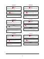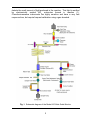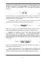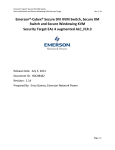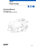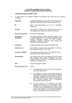
1
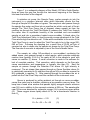
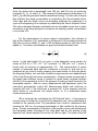
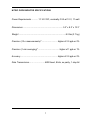
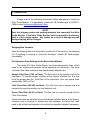
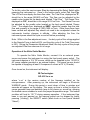
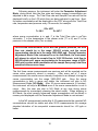
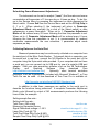
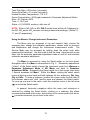
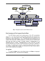
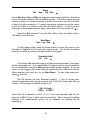
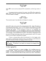
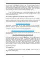
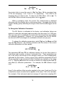
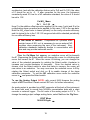
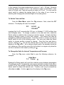
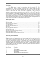
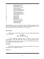
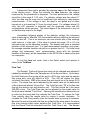
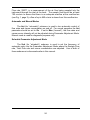
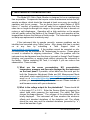
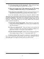
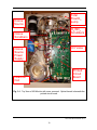
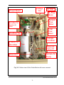
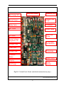
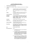
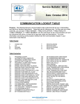
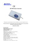
Nitric Oxide Monitor 2B Technologies, Inc. OPERATION MANUAL Model 410 © Copyright 2010-2013, 2B Technologies, Inc. All rights reserved. Nitric Oxide Monitor Manual Rev. E i TABLE OF CONTENTS IDENTIFICATION RECORDS iii PRINTING HISTORY iv WARRANTY STATEMENT v WARNINGS vii NITRIC OXIDE MONITOR INTRODUCTION 1 SCHEMATIC DIAGRAM 2 SPECIFICATIONS 7 OPERATION 8 PRE-OPERATION FLOW SETTING 8 MENU 14 MAINTENANCE/TROUBLESHOOTING 24 LABELED INSTRUMENT PHOTOS 29 PARTS LIST 33 Nitric Oxide Monitor Manual Rev. E ii IDENTIFICATION RECORDS Record the following information for future reference: Unit serial number: ______________________________________ Warranty start date: _______________________________________ (date of receipt) Nitric Oxide Monitor Manual Rev. E iii PRINTING HISTORY New editions are complete revisions of the manual and incorporate all previous update pages and write-in instructions. This manual will be revised as necessary. Revisions can be in the form of new editions, update pages, or write-in instructions. Revision A .......................................................................................... March 2010 Revision B ........................................................................................ August 2010 Revision C ...................................................................................... October 2010 Revision D …………....................................................................... January 2013 Revision E ………………………………………………………………. August 2014 TRADEMARKS & PATENTS 2B Technologies, 2B Tech, 2B, NO Monitor, Nitric Oxide Monitor and NOzone are trademarks of 2B Technologies, Inc. CONFIDENTIALITY The information contained in this manual may be confidential and proprietary, and is the property of 2B Technologies, Inc. Information disclosed herein shall not be used to manufacture, construct, or otherwise reproduce the goods disclosed herein. The information disclosed herein shall not be disclosed to others or made public in any manner without the expressed written consent of 2B Technologies, Inc. © Copyright 2010, 2B Technologies, Inc. All rights reserved. Nitric Oxide Monitor Manual Rev. E iv WARRANTY STATEMENT 2B Technologies, Inc. warrants its products against defects in materials and workmanship. 2B Technologies will, at its option, repair or replace products which prove to be defective. The warranty set forth is exclusive and no other warranty, whether written or oral, is expressed or implied. 2B Technologies specifically disclaims the implied warranties of merchantability and fitness for a particular purpose. Warranty Periods The warranty period is one (1) year from date of receipt by the purchaser, but in no event more than thirteen (13) months from original invoice date from 2B Technologies, Inc. Warranty Service Warranty Service is provided to customers through phone support, Monday Friday, from 9:00 a.m. to 5:00 p.m., Mountain Time USA, or by submission of a tech support ticket at www.twobtech.com/techsupport. Phone support is for troubleshooting and determination of parts to be shipped from 2B Technologies to the customer in order to return the product to operation within stated specifications. If phone support is not efficient and effective, the product may be returned to 2B Technologies for repair or replacement. Prior to returning the product, a Repair Authorization Number (RA) must be obtained from the 2B Technologies Service Department. Shipping 2B Technologies will pay freight charges for replacement or repaired products shipped to the customer site. Customers shall pay freight charges for all products returning to 2B Technologies. Conditions The foregoing warranty shall not apply to defects resulting from improper or inadequate maintenance, adjustment, calibration or operation by customer. Maintenance, adjustment, calibration or operation must be performed in accordance with instructions stated in the Nitric Oxide Monitor Operation Manual. Usage of maintenance materials purchased from suppliers other than 2B Technologies will void this warranty. Limitation of Remedies and Liability The remedies provided herein are the Customer's sole and exclusive remedies. In no event shall 2B Technologies be liable for direct, indirect, special, incidental or consequential damages (including loss of profits) whether based on contract, tort or any other legal theory. The Nitric Oxide Monitor Operation Manual is believed to be Nitric Oxide Monitor Manual Rev. E v accurate at the time of publication and no responsibility is taken for any errors that may be present. In no event shall 2B Technologies be liable for incidental or consequential damages in connection with or arising from the use of the Nitric Oxide Monitor Operation Manual and its accompanying related materials. Warranty is valid only for the country designated on the 2B Technologies quote or invoice. Nitric Oxide Monitor Manual Rev. E vi ENGLISH ESPAÑOL WARNING: Any operation requiring access to the inside of the equipment, could result in injury. To avoid potentially dangerous shock, disconnect from power supply before opening the equipment. ATENCION: Cualquier operación que requiera acceso al interior del equipo, puede causar una lesión. Para evitar peligros potenciales, desconectarlo de la alimentación a red antes de abrir el equipo. WARNING: ATENCION: This symbol, on the instrument indicates that the user should refer to the manual for operating instructions. Este símbolo, en el instrumento indica que el usuario debería referirse al manual para instrucciones de funcionamiento. WARNING: If this instrument is used in a manner not specified by 2B Technologies, Inc. USA, the protection provided by the instrument may be impaired. ATENCION: Si este instrumento se usa de una forma no especificada por 2B Technologies, Inc., USA, puede desactivarse la protección suministrada por el instrumento. FRANÇAIS DEUTSCH ATTENTION: WARNHINWEIS: Chaque opération à l’intérieur de l’appareil, peut causer du préjudice. Afin d’éviter un shock qui pourrait être dangereux, disconnectez l’appareil du réseau avant de l’ouvrir. Vor dem Öffnen des Gerätes Netzstecker ziehen! WARNHINWEIS: Dieses, auf dem Gerät weist darauf hin, dab der Anwender zuerst das entsprechende Kapitel in der Bedienungsanleitung lesen sollte. ATTENTION: Le symbol, d’instructions. indique que l’utilisateur doit consulter le manuel WARNHINWEIS: Wenn das Gerät nicht wie durch die Firma 2B Technologies, Inc., USA, vorgeschrieben und im Handbuch beschrieben betrieben wird, können die im Gerät eingebauten Schutzvorrichtungen beeinträchtigt werden. ATTENTION: Si l’instrument n’est pas utilisé suivant les instructions de 2B Technologies, Inc., USA, les dispositions de sécurité de l’appareil ne sont plus valables. ITALIANO DUTCH ATTENZIONE: OPGELET: Qualsiasi intervento debba essere effettuato sullo strumento può essere potenzialmente pericoloso a causa della corrente elettrica. Il cavo di alimentazione deve essere staccato dallo strumento prima della sua apertura. Iedere handeling binnenin het toestel kan beschadiging veroorzaken. Om iedere mogelijk gevaarlijke shock te vermijden moet de aansluiting met het net verbroken worden, vóór het openen van het toestel. OPGELET: ATTENZIONE: Het symbool, geeft aan dat de gebruiker de instructies in de handleiding moet raadplegen. Il simbolo, sullo strumento avverte l’utilizzatore di consultare il Manuale di Istruzioni alla sezione specifica. OPGELET: Indien het toestel niet gebruikt wordt volgens de richtlijnen van 2B Technologies, Inc., USA gelden de veiligheidsvoorzieningen niet meer. ATTENZIONE: Se questo strumento viene utilizzato in maniera non conforme alle specifiche di 2B Technologies, Inc. USA, le protezioni di cui esso è dotato potrebbero essere alterate. Nitric Oxide Monitor Manual Rev. E vii 1. NITRIC OXIDE MONITOR INTRODUCTION The 2B Technologies Nitric Oxide Monitor is designed to enable accurate measurements of nitric oxide (NO) concentrations in air without the use of a calibration gas standard. The most common application is the measurement of NO in urban and regional air pollution where the concentration is a few ppb or higher. Because of the absolute nature of the measurement, the Nitric Oxide Monitor may also be used to quantify the concentrations of calibration gas standards required by other techniques such as the commonly used NO + O3 chemiluminescence method. The highly sensitive chemiluminescence method is required when the NO concentration is 2 ppb. For measurements at low ppb levels and higher the Nitric Oxide Monitor has advantages over chemiluminescence of portability (small size and weight, low power consumption) and lack of requirement of a gas calibration standard. A U.S. patent (U.S. Patent No. 7,045,359; May 16, 2006) has been issued for this new detection technique. The Model 410 NO Monitor may be used in combination with the Model 401 NO2 Converter for measurement of NOx, and NO2 may be determined by difference (NO2 = NOx – NO), as in the chemiluminescence method. Theory of Operation The NOzone™ technology employed by the Model 410 Nitric Oxide Monitor™ is based on the quantitative reaction of nitric oxide (NO) with ozone (O3): NO + O3 → NO2 + O2 + light (1) This reaction has long been used as a gas phase titration for the measurement of either NO or O3 in laboratory kinetics experiments, and the reaction is stoichiometric; i.e., one O3 molecule is consumed for every NO molecule oxidized to NO2 in the reaction. In the Model 410 Nitric Oxide Monitor™, a small concentration of ozone (~4 ppm) is added to the gas sample stream and the resulting decrease in concentration of ozone is measured by the absolute method of UV absorbance. By providing adequate time for the reaction to go to completion, the decrease in ozone concentration is equal to the original concentration of NO in the gas stream. Reaction (1) also is used in conventional chemiluminescence analyzers. Instead of measuring the change in ozone concentration, chemiluminescence Nitric Oxide Monitor Manual Rev. E 1 detects the small amount of light produced in the reaction. That light is emitted by electronically excited NO2 molecules formed in reaction (1). Chemiluminescence instruments are highly sensitive and have a very fast response time, but require frequent calibration using a gas standard. Fig. 1. Schematic diagram of the Model 410 Nitric Oxide Monitor. Nitric Oxide Monitor Manual Rev. E 2 Figure 1 is a schematic diagram of the Model 410 Nitric Oxide Monitor. Here we trace the gas flow through the instrument beginning at the Sample Inlet near the bottom of the diagram. A miniature air pump, the Sample Pump, pushes sample air into the instrument to a miniature solenoid valve which alternately directs the flow through a Sample NO Scrubber or bypass. The sample air next passes through the sample flow meter and then into an overflow tee which vents part of the air sample. The Total Flow Pump (top of diagram) draws sample air from the overflow tee through the Total Flow Meter to measure the Total Flow, through the nafion tube to equilibrate humidity of the scrubbed and non-scrubbed sample air and into a proprietary heated ozone scrubber. A bleed valve, the Total Flow Adjustment Valve, is used to provide course adjustment of the Total Flow rate through the detection cell. Pulse-width modulation to the motor of the Total Flow Pump is used to adjust the Total Flow rate to be in the range 550650 cm3/min. Following the sampling tee, a small flow of 20-30 cm3/min of ozonized air also is drawn into the sample air stream by the Total Flow Pump. The flow rate of ozone/air is adjusted by use of the Ozone Needle Valve. The sample air, either NO-scrubbed or non-scrubbed, containing the added ozone, next passes through a coiled reactor, which provides adequate reaction time (typically 3.5-4.5 s) for nearly all NO in the sample to react with ozone via reaction (1) above. A small correction is made in the software for lack of complete reaction. That correction, which depends on the flow rate, ozone concentration and temperature, is typically less than 3%. Next the sample air passes through the Detection Cell where UV light intensity is measured. The air stream then passes through an Ozone Scrubber where O 3 is catalytically converted to O2 and then through an NO2 scrubber to remove the NO2 produced in reaction (1). After passing through the scrubbers the air is pulled into the Total Flow Pump and then vented into the instrument case. Ozone is produced by pulling ambient air through an ozone scrubber, ozone flow meter and a chamber containing a low pressure mercury lamp. The lamp has a fused silica window that passes highly energetic atomic emission near 185 nm in addition to the resonant emission at 254-nm. The wavelengths near 185-nm are absorbed by molecular oxygen (O2) to produce oxygen atoms (O). Those oxygen atoms rapidly attach to O2 via a termolecular reaction to form O3. O2 + photon → 2 O (2) O + O2 + M → O3 + M (3) Nitric Oxide Monitor Manual Rev. E 3 Here, the photon has a wavelength near 185 nm, and M is any air molecule, principally N2, O2, Ar and H2O. The molecule M catalyzes the combination of O and O2 by removing excess relative translational energy. The flow rate of ozone flow and thus the ozone concentration is controlled by the Ozone Needle Valve. Flow rates and the actual ozone concentration produced are measured in a cycle at the beginning of an analysis by modulating the Ozone Solenoid Valve. This valve alternates between scrubbed and non-scrubbed ozone flow to enter the stream of air being analyzed to measure the standing ozone concentration in the model 410. For the measurement of ozone reagent concentration, the intensity of light at the Detection Cell photodiode is measured in NO-scrubbed sample air that has no ozone added (Io) and in NO-scrubbed sample air that has ozone added (I). The ozone concentration is given by the Beer-Lambert Law: CO3 1 Io ln l I (4) where l is the path length (15 cm) and is the absorption cross section for ozone at 254 nm (1.15 x 10⁻¹⁷ cm2 molecule-1 or 308 atm-1 cm-1), which is known with an accuracy of approximately 1%. The concentration of ozone reagent is measured each time the instrument is turned on and can be remeasured at any time by briefly pressing the select switch on the front panel. As discussed below, one can also schedule measurements and readjustments of the Total Flow rate and ozone concentration. Reagent ozone is measured to be certain that sufficient ozone is present to cause nearly complete reaction with NO in the sampled air and for the purpose of making a small correction for incomplete reaction. After an ozone measurement and adjustment cycle, the instrument automatically enters NO Measurement Mode and continues to measure NO until 1) the instrument is powered off, 2) the operator uses the select button to re-measure and adjust ozone, or 3) a scheduled ozone measurement occurs. NO is measured by modulating the NO Solenoid Valve. A low-pressure mercury lamp is located on one side of the absorption cell, and a photodiode is located on the opposite side. The photodiode has a built-in interference filter centered on 254 nm, the principal wavelength of light emitted by the mercury lamp. Shorter wavelengths of light that could produce ozone are absorbed by the low-grade quartz envelope of the lamp itself and by the window of the detection cell, which passes 254-nm but not 185-nm light. The state of the NO Nitric Oxide Monitor Manual Rev. E 4 Solenoid Valve is switched every 10 seconds in order to measure light intensities for sample air, I, and scrubbed sample air, Io. The values of I and Io are used to calculate the concentration of NO in the original air sample by equation 5: C NO 1 I ln l I o (5) Note that because ozone decreases when NO is present, the log term is inverted as compared to the normal writing of the Beer-Lambert Law, with I in the numerator and Io in the denominator. A correction is made for the small amount of dilution of the NO concentration by the added ozonized air, as shown in equation 6: (CNO )corrected Ftotal Fozone CNO measured Ftotal (6) Where (Ftotal+Fozone)/Ftotal is the correction factor (typically less than 5%) for dilution of the sample gas by the addition of ozone/air to the Detection Cell. Application of equations 4 and 5 give ozone and nitric oxide concentrations, C, in units of molecules/cm3. The pressure and temperature within the absorption cell are measured using miniature sensors in order to calculate the total concentration of gas molecules. This allows nitric oxide and ozone concentrations to be expressed as mixing ratios in parts-per-billion by volume (ppb): T ( K ) 1013.25 9 10 X ( ppb) C 273 . 15 P ( mbar ) (7) Note that the abbreviations ppb and ppm refer throughout this manual to volume/volume or mole/mole ratios. Finally, a small correction (~1%) for incomplete reaction is made to the measured NO concentration based on the reagent ozone concentration and reaction time (determined by total volumetric flow rate and reactor volume). Nitric Oxide Monitor Manual Rev. E 5 In principle, the measurement of ozone by UV absorbance requires no external calibration; it is an absolute method. However, non-linearity of the photodiode response and associated electronics can result in a small measurement error. Therefore, each Nitric Oxide Monitor is itself calibrated against a nitric oxide standard gas, the concentration of which is periodically verified by a 2B Technologies Nitric Oxide Calibrator, whose calibration is traceable to a NIST standard. The corrections for offset and slope are recorded in the instrument Birth Certificate and on a calibration sticker that can be viewed by removing the top cover of the instrument. These calibration parameters are entered into the microprocessor prior to shipment. It is recommended that the instrument be returned to 2B Technologies for cleaning of the flow path, replacement of chemical scrubbers and recalibration at least once annually. Nitric Oxide Monitor Manual Rev. E 6 NITRIC OXIDE MONITOR SPECIFICATIONS Power Requirements ............ 11-14 V DC, nominally 0.9 A at 12 V, 11 watt Dimensions .................................................................... 5.3” x 8.3” x 13.3” Weight ................................................................................8.2 lbs (3.7 kg) Precision (10-s measurements)* ........................... higher of 2.5 ppb or 2% Precision (1-min averaging)* .................................... higher of 1 ppb or 1% Accuracy ............................................................... higher of 2.5 ppb or 2% Data Transmission………………….. 4800 baud, 8 bits, no parity, 1 stop bit Nitric Oxide Monitor Manual Rev. E 7 2. OPERATION Please read all the following information before attempting to install the Nitric Oxide Monitor. For assistance, please call 2B Technologies at (303)2730559 or email [email protected]. NOTE: Save the shipping carton and packing materials that came with the Nitric Oxide Monitor. If the Nitric Oxide Monitor must be returned to the factory, pack it in the original carton. Any repairs as a result of damage incurred during shipping will be charged. Shipping Box Contents Open the shipping box and verify that it contains all of the items on the shipping list. If anything is missing or obviously damaged, contact 2B Technologies immediately. Pre-Operation Flow Settings of the Nitric Oxide Monitor The model 410 Nitric Oxide Monitor has three independent flows, which need to be verified and adjusted before operating the instrument. The three volumetric flow rates measured and independently adjusted are: Sample Flow Rate (>700 cm3/min): The flow rate into the sample inlet of the instrument. To provide proper overflow at the internal overflow tee, this flow must be greater than the Total Flow of the instrument. One can expect flows greater than 1000 cm3/min. Total Flow Rate (580-620 cm3/min): The total flow rate of sample gas and ozone/air through the reaction coil and detection cell. Ozone Flow Rate (20-30 cm3/min): The flow rate of ozone/air mixed into the Total Flow stream. These flow rates are adjusted to be in the ranges specified above at the factory. However, due to changes in altitude and thus pressure, the three flow rates need to be verified and adjusted to be within the specified ranges if necessary. Nitric Oxide Monitor Manual Rev. E 8 To do this, enter the service menu (Svc) by depressing the Select Switch while powering the instrument on. Once in the service menu, select Tst, then Flw. The LCD will now display the three flow rates. The Total Flow, displayed as TF, should be in the range 580-620 cm3/min. This flow can be adjusted by the needle valve located on the back panel labeled “Total Flow”. The Ozone Flow, displayed as O3F, should be in the range 20-30 cm3/min. The Ozone Flow can be adjusted by the needle valve located on the back panel labeled “Ozone Flow”. The sample flow, displayed as SMPF, should be greater than the total flow and normally in the range of 1000-1500 cm3/min. Once these flows have been verified and adjusted they should not need to be re-adjusted unless the instruments location changes in altitude. After adjusting the flow, the instrument power should be cycle on and off before proceeding. Note: While in the flow adjustment menu, the duty cycle of the voltage applied to the Sample Pump is held at 60%, and the duty cycle of the Total Flow pump is 50%. During the Parameter Adjustment Mode, the duty cycles of the pumps are adjusted if the flow rates are out of range. Operation of the Nitric Oxide Monitor To operate the Nitric Oxide Monitor, connect it to an external power source and power the instrument on using the front panel power switch. The instrument requires a 12 V DC source, which can be supplied by the 110-220 V AC power adapter provided or an external battery. The power source should be capable of supplying at least 2.5 amperes of current at 12 V (30 watts). Once turned on, the instrument will display: 2B Technologies NO 410 Ver x.xx where “x.xx” is the version number of the firmware installed on the microprocessor. After powering up, the instrument will begin a 20-minute WARMUP mode. During this period a count down of time in minutes and seconds will appear on the display. This warm up time is critical to allow the ozone generator lamp and detection lamp to fully warm up, as well as, allowing the heated ozone scrubber to reach the proper temperature range. The heated scrubber will heat to 110 oC during warmup operation. If the instrument has been in use and warmed up, the warmup period can be skipped by briefly pressing (“clicking”) the SELECT switch (black knob on front panel labeled “Select”). Nitric Oxide Monitor Manual Rev. E 9 Following warmup, the instrument will enter the Parameter Adjustment Mode, during which time the flow rates and ozone reagent concentration are adjusted to be in range. The Total Flow rate and Sample Flow rate will first be displayed briefly on the LCD while they are being adjusted in real time. Next, the ozone concentration will be displayed on the LCD, along with the Total Flow rate, temperature and pressure every 10 seconds; for example: O3= 4537 T= 28.2 P= 997.7 where ozone concentration is in ppb, F is the Total Flow rate in cm3/min volumetric, T is the temperature in the chosen units (oC or K) and P is the pressure in the chosen units (Torr or mbar). For accurate measurements of NO with the greatest precision, the total flow rate should be in the range 550-650 cc/min and the ozone concentration should be in the range 3000-5000 ppb. During Parameter Adjustment Mode if the instrument is set to Auto Mode, the instrument will attempt to adjust the sample flow to 1000-1200cc/min, total flow to 580-620cc/min and ozone concentration to the narrower range of 38004200 ppb by pulse width modulation of the sample flow pump, total flow pump and ozone source lamp. The first three ozone measurements are spurious and will be reported as the ozone value previously stored in memory. After every set of 3 ozone measurements, the ozone source intensity is adjusted in an attempt to bring the ozone concentration into the range 3800-4200 ppb. Once the ozone concentration is both in range and stable, the instrument will skip to NO Measurement Mode (NO Mode). After 30 ozone measurements (5 minutes), the instrument will skip to NO Mode even if the ozone concentration is not in range. Also, the user can skip to NO Mode at any time during ozone measurements by momentarily pressing the select switch. When skipping to NO Mode, the most recently measured ozone concentration will be stored in memory and displayed until the Parameter Adjustment Mode is next entered. In the NO measurement mode after 5-10 measurements the reported NO concentrations should be stable and after 20-30 measurements the average standard deviation of ten sequential measurements should be 2.0 ppb or better. Nitric Oxide Monitor Manual Rev. E 10 Scheduling Ozone Measurement Adjustments The instrument can be set to readjust (“tweak”) the flow rates and ozone concentration at frequencies of 1 time per day or 4 times per day. To do this, go to the Service Menu by powering the instrument on while depressing the select switch. Choose Sch from the Service Menu and set the O3 Adj Freq to 0, 1 or 4. When selecting 0, the instrument will return to Parameter Adjustment Mode only manually (by a click of the Select switch) or after experiencing a power interruption. When set to 1, Parameter Adjustment Mode will be entered every 24 hours following the time this parameter is set. When set to 4, Parameter Adjustment Mode will be entered every 6 hours following the time this parameter is set. It is recommended for ambient continuous measurements the user schedules 1 parameter adjust mode sequence per day. Collecting Data over the Serial Port Measured parameters may be continuously collected on a computer from the serial port of the Nitric Oxide Monitor. To transmit data to a computer over the serial port in real time, connect the NO Monitor to the serial port of the computer using the 9-pin serial cable provided. If your computer does not have a serial port, you can connect via its USB port by use of a serial-to-USB port adaptor. Start your data acquisition software; such as the 2B Technologies Display and Graphing Software (free download from http://twobtech.com/software.htm). Optionally, other terminal emulation programs, such as Hyperterminal (included with Microsoft Windows) or Tera Term Pro can be used. A free download of Tera Term Pro is available at: http://hp.vector.co.jp/authors/VA002416/teraterm.html In addition to data lines, messages are written to the serial port to describe the functions being performed. A complete Parameter Adjustment Mode cycle followed by output of NO measurements produces the following lines of data, for example: Setting sample flow rate… Setting total flow rate… Total Flow = 593 cc/min Measuring Generated Ozone Signal Photodiode voltage = 1.45 V Lamp Duty Cycle @ 71% Total Flow Pump Duty Cycle @ 48% Sample Flow Pump Duty Cycle @ 45% total flow rate should be in the range 0.7 – 2.0 v should be less then 75% should be 42-90% should be 42-90% Nitric Oxide Monitor Manual Rev. E 11 Avg: 10 s/rdg NO2, NO, NOx, Temp, Press, SampleFlow, TotalFlow, O3Flow, ScrubberTemp, O3, Date, Time, Status General Header for serial line of 410 data data line 1 data line 2 date line 3 ………….. data line 30 Flow correction factor = 1.03 Incomplete Reaction Correction Factor = 1.01 Lamp Duty Cycle @ 71% Total Flow Pump Duty Cycle @ 48% Sample Flow Pump Duty Cycle @ 45% Should be in range 1.00-1.10 Should be in range 1.00-1.10 Should be in range 50-75% Should be in range 42-90% Should be in range 42-90% The instrument will then begin measuring NO concentration and write to the serial port: Measure NO2 and NO Concentration In given NO, NO2, NOx mode selected in menu O3 Adjust Frequency = 0 times/day Frequency of auto adjust selected in Svc menu Avg: 10 s/rdg Averaging time selected in Avg menu NO2, NO, NOx, Temp, Press, SampleFlow, TotalFlow, O3Flow, ScrubberTemp, O3, Date, Time, Status Header for NO data stream data line 1 data line 2 data line 3 ………….. Nitric oxide data will continue to be output until the Select Switch is used to enter the Menu or the Parameter Adjustment mode. As an example, a typical data line for NO reads: 9.2, 14.3, 23.5, 35.3, 836.5, 1084, 603, 21, 110.2, 4190, 21/02/12, 13:16:41, 81 Where: NO2 = 9.2 ppb NO = 14.3 ppb NOx = 23.5 ppb (sum of NO + NO2) Cell temperature = 35.3 oC (if oC units have been selected) Cell pressure = 836.5 mbar (if mbar units have been selected) Sample Flow Rate = 1084 cc/min (volumetric) Nitric Oxide Monitor Manual Rev. E 12 Total Flow Rate = 603 cc/min (volumetric) Ozone Flow Rate = 21 cc/min (volumetric) Heated Scrubber Temperature = 110.2 oC Ozone Concentration = 4190 ppb (measured in Parameter Adjustment Mode) Date = 21 February 2012 Time = 1:16:41 pm Status = 81, NO/NO2 mode on, with zero off NOTE: When in NO, NO2 or NOx ONLY modes there will be a 0.0 displayed in the NO, NO2 and/or NOx columns not being measured accordingly. (Status 21, 11, and 41 respectively) Using the Menu to Change Instrument Parameters The Menu may be accessed to log and transmit data, choose the averaging time, change the calibration parameters, choose units for pressure and temperature and change the instruments measurement mode. The Service Mode may be accessed by holding down the select knob while powering the instrument. Use this mode to test the lamp, output smooth or raw data, turn the automatic parameter adjustment mode on and off, and schedule automatic parameter adjustment. The Menu is accessed by using the Select switch on the front panel. Navigation within the Menu is summarized in Fig. 2. Momentary depressions (“clicks”) of the Select switch change the instrument mode from Warmup to Parameter Adjustment Mode to NO Mode and back to Parameter Adjustment Mode. Depressing the Select switch for a time longer than about 1 second accesses the Menu. Within the Menu, rotating the select switch moves a blinking cursor back and forth between the four submenus, Dat, Avg, Cfg and NOx. To enter a submenu, position the cursor under the first letter of the submenu name and “click” (quickly press and release) the Select switch. To move up one level in the menu, move the underline cursor to the left arrow () and click the Select switch. In general, horizontal navigation within the menu and submenus is achieved by rotating the Select switch, clicking on a submenu title allows movement downward in the menu, and clicking on the return symbol (left arrow, ), provides movement up one level in the menu. Nitric Oxide Monitor Manual Rev. E 13 Press Select Warmup Press Select Par. Adj. Mode Press & Hold Select Press & Hold Select Press Select NO Mode Press & Hold Select Main Menu Dat Xmt Log End End D/T 10 s 1 min 5 min 1 hr D/T: 10:32:21 17/10/2006 Fm = 1.00 NOx Cfg Avg Sfl Tfl Cal NO Vot Mode: click and scroll to select NO, NO2, NOx or NO and NO2 mode Unt NO2 T:C P:mbar 1V=200 ppbv Fm = 0.78 Z= 2 S=1.04 Z=-2 S=1.21 Fig. 2. Navigation chart for the NO Monitor menu. Data Averaging and Data Logging Using the Menu The NO Monitor reports new measurements of the NO concentration every 10 s. You may choose to average these data within the instrument for periods of 1 min, 5 min and 1 hour. Also, data lines may be stored in the instrument’s internal data logger. Up to 16,383 data lines containing the log number, NO mixing ratio, internal temperature, internal pressure, total flow rate, date and time may be stored in internal memory, corresponding to an operational time of 1.9 days. Averaging times of 1 min, 5 min and 1 hr also may be selected from the menu, thereby allowing the instrument to operate for 1.6 weeks, 1.9 months and 1.9 years, respectively, before filling the memory. For virtually unlimited data storage, we recommend the flash memory option, which is also available as an upgrade. To Log Data To reach the Menu, hold in the Select button until Menu is displayed. Then release the button. The panel will now display: Nitric Oxide Monitor Manual Rev. E 14 Dat Menu Avg Cfg NOx where Dat, Avg, Cfg and NOx are submenus that may be selected. A blinking cursor will show across the D of the Dat submenu. The Select switch may be rotated clockwise or counterclockwise to position the cursor over the first letter of one of the other submenus. To select a particular submenu, move the cursor to the first letter of a submenu and click the Select switch. To exit the menu and begin making measurements again, select and click on the left arrow (). Select the Dat submenu from the Main Menu using the Select button. The display will now show: Data Menu Xmt Log End To start logging data, rotate the Select switch to move the cursor to the first letter of Log and click to select the logging mode. You will then be asked whether you want to overwrite the data stored in the logger: Overwrite Data? No Yes If you select Yes and start logging, all data previously stored in the logger will be irretrievably lost. If you have data in the logger that you want to keep, be sure to download it using the Xmit function before starting logging. If you are ready to start logging, then select Yes by positioning the cursor and clicking. Either selection will return you to the Main Menu. To start data acquisition, select and click. The NO Monitor will then alternately display: 1) the O3 mixing ratio, internal temperature and internal pressure and 2) the NO mixing ratio and log number. For example, the display might read: NO= 32.4 ppb T=25.6 P=989.7 where the cell temperature is 25.6 oC (if oC units are selected), and the cell pressure is 989.7 mbar (if mbar units are selected). After 5 seconds (midway between 10-s measurement cycles), as an example, the display will be replaced by: Nitric Oxide Monitor Manual Rev. E 15 NO= 56.7 ppbv Log= 193:0 where NO is most recently measured NO concentration, and the log number is 193. If averaging has been selected, the ozone value (O3) will be replaced by AVG, which is the most recently calculated average value of NO, and the first screen will read for example: AVG= 57.3 T=25.6 P=989.7 The second screen (5 seconds later) will display for example: NO= 56.7 ppbv Log= 193:4 where NO is the most current 10-s measurement of NO. Again 193 refers to the most recent log number. The “4” in 193:4 refers to the number of 10-s data points that have been measured so far for inclusion in the next average to be displayed and logged. If 10-s averaging is used (i.e., no averaging), this number will always be 0. If 1-min averaging is used, this number will increment from 0 to 5; for 5-min averaging, the number will increment from 0 to 29; and for 1-hr averaging, it will increment from 0 to 359. This number is displayed so that the user will know how many more 10-s measurements need to be made before a new average is displayed and logged. If there is a power failure while the instrument is in the logging mode, when power is restored the instrument will go into Warmup mode followed by Parameter Adjustment Mode and logging of data will resume. Note: Once logging has started, you should not enter the menu, except to end logging. In particular, you should not change the averaging time during logging. To Stop Logging Data Hold the Select button in to obtain the Menu. Go to the Dat submenu by clicking on Dat. Choose and click on the End function. This will end data logging. You may now transmit the data to a computer by clicking on Xmt (see below). You may transmit the data as many times as you want. Alternatively, Nitric Oxide Monitor Manual Rev. E 16 you may return to the Menu by clicking on . The stored data will reside in memory (even when new measurements are being made) and can be transmitted using the Xmt function at a later time. However, all stored data are lost once logging is started again using the Log function. Thus, you should always transmit your data to a computer before restarting logging. If you fail to End logging prior to transmitting the data using the Xmt function, the instrument will automatically execute the End function for you before transmitting the data. To Transmit Logged Data to a Computer Using the Serial Port Connect the serial port of the instrument to the serial port of your computer using the cable provided. Start your data acquisition software; such as the 2B Technologies Display and Graphing Software, which can be downloaded at: http://twobtech.com/software.htm Alternatively, Hyperterminal can be used (available on most Windows platforms, usually in Start/All Programs/Accessories/Communications/Hyper Terminal) or Terra Term Pro, which can be downloaded at: http://hp.vector.co.jp/authors/VA002416/teraterm.html For more details on the use of Tera Term Pro and Hyperterminal, see our Tech Note #007 here: http://www.twobtech.com/tech_notes/TN007.pdf Hold down the Select button to obtain the Main Menu. Go to the Dat submenu by clicking on Dat. Next, click on Xmt. The message “Logged Data” will be written to the serial port, followed by a carriage return and all of the lines of logged data. After all data are transmitted, the message “End Logged Data” and a carriage return are written. After transmission is complete, you can return to any position in the menu or resume NO measurements. The logged data continues to reside in memory and be available for transmission until a new data log is started. To Average Data Hold down the Select button to obtain the Menu. Select and click on Avg to obtain the Avg menu: Nitric Oxide Monitor Manual Rev. E 17 10s Avg Menu 1m 5m 1h Use single clicks to move the cursor to 10s, 1m, 5m or 1h for averaging times of 10s (no averaging), 1 min, 5 min or 1 hr, respectively. Then click on the averaging time you want to use. To return to the Main Menu, click on . To exit the Main Menu and start acquiring data, click on again. While in averaging mode, the current 10-s measurement is displayed alternately with the average value, as discussed above. Averaged data may be logged, thereby greatly extending the length of time that the data logger can be used. To Change the Calibration Parameters The NO Monitor is calibrated at the factory, and calibration factors are entered to make the instrument read accurately over the range 0 to 1,000 ppb. The user may wish to recalibrate the instrument from time to time and change the calibration parameters. However, it is recommended that the NO Monitor be returned to 2B Technologies for recalibration at least once per year. To change the calibration parameters, select Cfg from the Menu and Cal from the Cfg submenu. The following submenu with the values of the current calibration parameters will then appear: Cal Menu SFl TFl NO NO2 The parameters SFl and TFl are calibration factors for the two flow meters to make them read correctly in terms of volumetric flow. These parameters are set in the factory and should not be changed unless you have independently calibrated the flow meters. Factory values of the calibration parameters Sfl and Tfl are recorded in the instrument’s Birth Certificate are typically in the range 0.8-1.2. Selecting NO allows one to enter a submenu for entering the slope (S) and offset (Z) calibration parameters. For example, the NO submenu might read: Cal NO Menu Z= -2 S= 1.02 Here Z is the additive offset correction applied (in this case -2 ppb) and S is the multiplicative slope correction factor applied (in this case 1.02) to the raw data. For example, if the instrument reads an average of 3 ppb when sampling NONitric Oxide Monitor Manual Rev. E 18 scrubbed air (and with the calibration factors set to Z=0 and S=1.00), the value of Z should be set to –3. If after correction for the zero, the instrument consistently reads 2% low for a NO calibration standard, the value of S should be set to 1.02. Cal NO2 Menu Z= 1 S= 1.32 Here Z is the additive offset correction applied (in this case 1 ppb) and S is the multiplicative slope correction factor applied (in this case 1.32) to the raw data. Note the NO2 slope factor is based primarily on the molly converter efficiency and it is typical to be in the 1.20-1.50 range and should be checked periodically for converter efficiency loss. A few words of caution: Compressed air cylinders often contain traces of NO, so it is necessary to use an external NO scrubber when measuring the zero of the instrument. Also, calibration standards frequently decline in concentration with time and may provide inaccurate results. When the Cal Menu first appears, an underline cursor will be beneath the Z. Depressing the Select switch will change this cursor to a blinking dark cursor that covers the Z. When the cursor is blinking, you can change the value of the selected parameter by rotating the Select switch (clockwise to increase and counter-clockwise to decrease). Once the desired value is chosen, click the Select switch to store that value in memory; the cursor will now return to an underline. You may now move the underline cursor to S by rotating the Select switch and click on S to enable change of the slope calibration parameter. To exit the NO calibration menu move the underline cursor to and press the Select switch. To use the Analog Output (NOTE: with current 9.4B firmware the analog output is NOT functional. Please contact 2B Tech. for further information.) An analog output is provided via a BNC connector at the back of the instrument for those who want to record their NO/NOx concentration data with a chart recorder or external logger. The full scale of the analog output is 2.5 V. To change the analog output voltage scaling factor, select Vot from the Cfg Menu: VOUT Menu 1V=000100 ppb Nitric Oxide Monitor Manual Rev. E 19 In this example, the output scaling factor is set as 1 Volt = 100 ppb. Since the maximum output voltage is 2.5 V, the maximum output concentration in this case is 250 ppb, and 1 ppb will provide an output of 2.5 mV. You can use the select switch to change the scaling factor to the value of your choice by selecting and changing the individual digits in the scaling factor. To Set the Time and Date From the Main Menu, select the Cfg submenu. Next, select the D/T submenu. The display will read, for example: D/T: 14:32:21 17/10/2012 meaning that it is 21 seconds after 2:32 p.m. on October 17, 2012 (military time and European date). To change a number in the date and time, rotate the Select switch to underline the numeral you want to change. A single click then causes a blinking cursor to cover that numeral. The number can then be changed by rotating the Select switch. Once the number is correct, click on the Select switch to turn off the blinking cursor. You may now rotate the Select switch to choose another numeral to change. Once the time and date is correct, clicking on will set the internal clock to that time and return the display to the Cfg menu. As in setting a digital watch, the seconds should be set in advance of the real time since the clock starts to run again only when the set time is entered; in this case by clicking on . To Change the Units for Internal Temperature and Pressure From the Cfg menu, select Unt to give the following submenu, for example: Units Menu T:C P:mbar Rotating the Select switch will cycle the underline cursor between temperature (T) and pressure (P). Temperature units may be selected as either Kelvin (K) or Celsius (C) by first clicking to obtain the blinking cursor and then rotating the Select switch to obtain the desired units. Pressure units may be selected as either torr or mbar. A click on returns the display to the Cfg menu. Nitric Oxide Monitor Manual Rev. E 20 NOx Menu The NOx menu is used in conjunction with the model 401 NO2 (molybdenum or “molly”) converter. Through use of valves inside the 401 converter the user can change between NO, NO2, NOx and NO and NO2 modes. In NO mode the “molly” converter is bypassed. In NO2 mode the sample air passes over the converter and into the 410. In NO x or NO and NO2 modes sample air is alternated between bypass and through the converter and then into the 410 monitor. Further details of this menu along with flow path and valve states can be found in the 401 NO2 converter user manual. If the Model 410 is not being used with a 401, this menu should remain unchanged and the molly status on the data line in NO mode should read 21. Status byte values: NO only mode ...…………................................................................................ 21 NO only with zero valve on ……………………………………………………….. 23 NO2 only mode ……………………………………………………………………..11 NO2 only with zero valve on ……………………………………………………….13 NOx only………………………………………………………………………………41 NOx only with zero valve on………………………………………………………..43 NO and NO2 mode…………………………………………………………………..81 NO and NO2 mode with zero valve on…………………………………………….83 Parameter adjust mode……………………………………………………………..91 Parameter adjust mode with zero valve on……………………………………….93 Accessing the Serial Menu Measurements and logging tasks can be accessed via the serial port or the USB using a terminal emulator such as Tera Term Pro or HyperTerminal running on an attached computer. Commands can be sent using the terminal emulator set with the properties listed in the section of this manual entitled “Collecting Data over the Serial Port in Real Time”. Listed below are letters (case sensitive) that are commands for performing certain operations while the instrument continues to run: Key_Stroke Function l t e a Start logging. End logging and transmit data. End logging. Set average and output frequency. Nitric Oxide Monitor Manual Rev. E 21 z s o b f g c p u h N X G B P ? x Set the NO zero offset. Set the NO slope. Set the NO2 zero offset. Set the NO2 slope. Set the Total flow slope. Set the Sample flow slope. Set the time and date. Lamp test with pump on. Lamp test with pump off. Serial header. Measure NO. Measure NOx. Measure NO2. Measure NO2 and NO. Parameter Adjustment. Output help menu. Exits serial menu. Additionally the user can turn on the zero valve in the 401 by pressing “Z” and can turn off the zero valve by pressing “Y” while in measurement mode. (Zero gas must be provided by user at the 401 zero air inlet port) Service Menu The Svc menu is reached by holding in the select switch while powering on the instrument: Svc Menu Adm Tst Aut Sch A data smoothing algorithm can be selected for long term measurements. Under Adm select Raw and the user is prompted to select Smooth Data?, select yes to turn on and no to turn off. NOTE: Smooth data is not available when in NO and NO2 mode. Test Menu The Tst menu allows the user to determine and adjust the instrument flow rates and run a diagnostic lamp test. Lamp Test Nitric Oxide Monitor Manual Rev. E 22 A diagnostic lamp test is provided by selecting Lmp in the Tst submenu of the Service menu. When first entering the Lmp submenu, the voltage measured by the photodiode is displayed. For best performance this voltage should be in the range 0.7-2.0 volts. For detector voltage less than about 0.7 volts, the data may be noisy due to insufficient light intensity to make precise measurements. If the voltage is zero, the lamp is not ignited and is either burned out or not receiving 5 V from the circuit board. For voltages above 2.0 volts, the A/D converter is saturated and the measured ozone and NO concentrations will be spurious. This could happen if the instrument is very hot so that the lamp output is too bright. Immediately following display of the detector voltage, the instrument starts measuring an “effective” NO concentration without switching the solenoid valve on and off. This is an electronic zero and should after a few readings settle down to ± a few ppb. If the value is outside the range -10 to +10, the instrument may not be operating correctly. The display also gives a standard deviation of the electronic zero. For best measurement precision (low noise), the average standard deviation should be no greater than ±3. The initial lamp voltage and subsequent “zero” measurements, along with the standard deviation of the lamp, will be transmitted on the RS232 line to observe the data on a computer. To exit the Lmp test mode, hold in the Select switch and release to return to the Tst Menu. Flow Test The Sample, Total and Ozone flow rates can be checked and adjusted if needed by selecting Flw in the Tst submenu of the Service Menu. Once there, the total flow/ozone flow pump will be set to a 50% duty cycle and the sample flow pump duty cycle will default to 60%. The LCD will display the three volumetric flow rates. O3F is the ozone flow and should be in the range 20-30 cc/min. The ozone flow can be adjusted by the needle valve on the back panel of the instrument labeled “Ozone flow”. The Total Flow rate, TF, is the flow rate through the reaction coil and detection cell. This flow should be in the range 550-650 cc/min. The Total Flow rate can be adjusted by the needle valve on the back panel labeled “Total Flow”. Opening this needle valve allows extra air to enter into the pump and thus reduces the Total Flow. To reduce the Total Flow, partially open the needle valve by turning it counter clockwise. To increase the Total Flow partially close the needle valve by turning it clockwise. Because the ozone flow and total flow are pulled by the same pump, the ozone flow may change slightly when adjusting the Total Flow. It is recommended that the Ozone Flow be rechecked once the Total Flow is set. The Sample Nitric Oxide Monitor Manual Rev. E 23 Flow rate, SMPF, is a measurement of the air flow being sampled into the instrument through the inlet at the back. The sample flow should be at least 700 cm3/min to assure that there is an adequate overflow at the overflow tee (see Fig. 1, page 2); a flow of up to 650 cc/min is drawn from this overflow tee. Automatic and Manual Modes The Aut (for “automatic”) submenu is used to turn automatic control of flow rates and ozone concentration on and off. For normal operation the Aut parameter should be set to On. If set to Man (“manual”), the flow rates and ozone source intensity will not be adjusted during Parameter Adjustment Mode. Manual mode is used for diagnostic purposes only. Schedule Parameter Adjustment Mode The Sch (for “schedule”) submenu is used to set the frequency of automatic entry into the Parameter Adjustment Mode where the Sample Flow rate, Total Flow rate and ozone concentration are adjusted. Use of both of these submenus is discussed earlier in this manual. Nitric Oxide Monitor Manual Rev. E 24 3. MAINTENANCE/TROUBLESHOOTING The Model 410 Nitric Oxide Monitor is designed to be as maintenance free as possible. Components that require routine maintenance include the NO sample scrubbers, which should be changed at least once every six months of operation and the air pumps. The air pumps have a rated lifetime of 5000 hours (~7 months) of operation and will need to be replaced when the flow rates can no longer be brought into range or the pumps fail due to burned out motors or split diaphragms. Operation with a high restriction on the sample inlet will greatly reduce the lifetime of the Sample Pump, and operation at low temperatures reduces the lifetimes of both pumps. The instrument is designed so that pump replacement is relatively easy. If the instrument fails to operate correctly, common problems can be identified and corrected using Table I below. Also, please feel free to contact us at any time by submitting a Tech Support ticket at www.twobtech.com/techsupport. If the problem cannot be corrected on site, the instrument may be returned to 2B Technologies for service. Please phone or email in advance for shipping instructions. Often, the problem with the instrument can be diagnosed over the phone, by email or through Tech Support ticketing, and corrections or repairs made without returning the instrument to the factory. Before contacting 2B Tech, it is helpful if you can make a few observations. These include: 1) What are the ozone concentration, NO concentration, temperature, pressure and flow rate displayed by the instrument on the front panel? If possible, collect data from the serial port for both the Parameter Adjustment Mode and NO Measurement Mode and submit a tech support ticket at www.twobtech.com/techsupport or email us at [email protected] with an explanation of the problem you are experiencing with the instrument. Please include s/n and firmware version with your submission. 2) What is the voltage output for the photodiode? These should fall in the range 0.7 to 2.4 V. Enter the Service Mode by pressing the select knob while powering the instrument. The select Tst, then choose the Lmp submenu. The voltages of the photodiode will be briefly displayed. The instrument will then measure the electronic offsets and standard deviations of the detection cell. The offsets should be near zero and the standard deviations (preceded by “±”) should be less than 3 ppb. Nitric Oxide Monitor Manual Rev. E 25 3) Is air being drawn into the instrument? Briefly hold your finger over the air inlet to determine whether there is suction. 4) What is the average value of NO measured when the NO zeroing scrubber is attached to the inlet (i.e., the instrument zero)? 5) How noisy is the instrument? Calculate the standard deviation of 10 sequential measurements with the external NO scrubber in place. If you feel comfortable working on the instrument, additional useful information can be provided by removing the top and bottom instrument covers. Annotated photographs of the inside of the instrument case and of the circuit board are given below. With the top and bottom removed power up the instrument. Useful questions that you can quickly answer once the top and bottom covers are removed are: 1) Is the ozone source lamp ignited? There should be a purple glow coming from the tubing attached to the ozone source located in the top of the instrument. 2) Is there an overflow of air? Place your finger on the overflow tee located in the bottom of the instrument and determine whether air is going into (incorrect) or out (correct) of the overflow tee. 3) Is there power to the board? Measure the dc voltage on the power inlet connector shown in Figure 3-3. It should be close to 12 V. The figures following Table I provide a “guided tour” of the instrument so that critical components and connectors may be easily identified. A list of serviceable parts is provided in Section 4 at the end of this manual. Nitric Oxide Monitor Manual Rev. E 26 Table I. Troubleshooting the Nitric Oxide Monitor for performance problems. Problem/symptom Instrument does not turn on. Likely cause Power not connected properly or circuit breaker tripped. Corrective action Check to see that the power adapter is supplied with 110 or 220 v ac power and that 12 v dc is reaching the circuit board. Display is blank or nonsense. Bad connection of display to circuit board. Remove top cover and reconnect display to circuit board. Check solder connections to display. Cell temperature reads low by several 10’s of degrees. Absent or loose connection of temperature probe cable to circuit board. Remove top cover and check attachment of temperature sensor connector to circuit board. Readings are noisy with standard or on external scrubber with standard deviations greater than 3.0 ppb. Lamp is not on. Check lamp connection to circuit board. Remove bottom cover, turn instrument on, and visually check to see that lamp turns on within a few seconds after the power switch is turned on. Return instrument for lamp replacement if lamp does not light. Lamp output is weak. Measure reference and sample photodiode using Svc submenu. If either voltage is less than 0.9 V DC, contact 2B Tech for lamp replacement. Nitric Oxide Monitor Manual Rev. E 27 Excessive vibration. Provide additional vibration insulation for the instrument such as a foam pad. Select switch does not work. Cable not properly connected between select switch and circuit board. Remove top cover and reconnect select switch cable to circuit board. Serial port does not work. Cable not properly connected between serial port 9-pin connector and circuit board. Remove top cover and reconnect serial port cable to circuit board. Wrong serial cable used. A “straight through” serial cable is provided. Some data collection devices require a ”cross over” cable in which pins 1 and 3 are exchanged between the two ends of the cable. Use a “cross over cable or additional connector that switches pins 1 and 3. Wrong baud rate is used. Make sure the baud rate of your data collection device is set at 4800. Required calibration Standard incorrect. parameters are excessively large when calibrated using a reference gas standard. NO scrubber is contaminated or NO standards are notoriously unstable and decrease in concentration with time. Try using another standard. Replace sample scrubber. Be sure to use Nitric Oxide Monitor Manual Rev. E 28 Instrument always reads close to zero for NO concentration. scrubbing capacity is depleted. Connecting tubing and/or absorption cells are contaminated. an inlet filter to remove particulate matter. Rinse cells and tubing with methanol and dry with zero air. Replace internal tubing with ¼” O.D., 1/8” I.D.Teflon-lined Tygon tubing (or silicone tubing where not in sample flow path). Solenoid valve cable is not properly connected to circuit board. Reattach solenoid valve cables to circuit board. Ozone generator not Verify generator is on making ozone or ozone and ozone valve is valve stuck in off position flipping in parameter adjust mode Instrument has large negative offset at zero Sample scrubber contaminated, common with long term exposure to high NO/NOx (greater than 1ppm) Replace sample scrubber Sample scrubber dried out from dry tank air in gas cylinder standards Add humidity to sample air line, with added humidity to the sample scrubber the offset should go to zero in time (a few hours of use) Heated scrubber malfunction and is passing ambient ozone Regenerate or replace heated scrubber Nitric Oxide Monitor Manual Rev. E 29 Total Flow/O3 pump Air Pump O3/NO2 Scrubbers s Ozone Source Ozone Scrubbers O3 Valve Ozone Source Power Supply Printed Circuit Board Reaction Coil Fig. 3-1. Top View of NO Monitor with cover removed. Optical bench is beneath the printed circuit board. Nitric Oxide Monitor Manual Rev. E 30 Voltage Out Power Board Air Inlet O3 Flow Meter Sample Flow Meter Scrubber for ozone air inlet Total Flow Meter Overflow Tee Tee Sample Scrubber Heated O3 Scrubber Housing Solenoid Valve #1 Sample Air Pump DewLine Fig. 3-2. Bottom view of Nitric Oxide Monitor with cover removed. Nitric Oxide Monitor Manual Rev. E 31 Det. Lamp, 5V Molly Zero Valve Power In, 12V Serial Output Sample Flow Pump Molly Valve O3 Source NO Valve Heater Relay O3 Valve Total Flow Pump Lamp Voltage Regulator, 5V O3 Scrubber Temperature Sample Flow Total Flow Photodiode Ozone Flow Pressure Meter Select Switch Display Power Jumper Cell Temp. Fig. 3-3. Printed Circuit Board. (Individual Instruments may vary.) Nitric Oxide Monitor Manual Rev. E 32 Voltage In 12 V Out to PCB 10 Watt Heater for Ozone Scrubber Relay Control for Heater On/Off Switch Fig. 3-4. Power Board. Nitric Oxide Monitor Manual Rev. E 33 4. PARTS LIST 1. NOSAMPUMP, (“A” Series Sample Pump for Model 410 Nitric Oxide Monitor) 2. NOTOTPUMP, ( “A” Series Total flow Pump for Model 410 Nitric Oxide Monitor) 3. NOSAMPSCR (Internal Sample Scrubber) 4. NOXEXTZEROSCRB (External NOx Zeroing Scrubber) 5. NOINTSCRB (Internal Ozone Scrubber) 6. NOOUTSCRB (NO Outlet scrubber set) 7. NOO3SCR (Carbon scrubber) 8. NOHEATSCR (heated scrubber assembly, including enclosure, heater, and scrubber housing and material) 9. NOVLVNO, (NO Valve for Model 410 Nitric Oxide Monitor nickel plated brass) 10. NOVLVOZ, (Ozone Valve for Model 410 Nitric Oxide Monitor, stainless steel) 11. NOOZSOURCE, (Ozone generator with UV lamp, Glass housing and Inverter) 12. NOLAMPAS (Lamp Assembly for Model 410 NO Monitor) 13. NOPDASM (Photodiode assembly for Model 410 Nitric Oxide Monitor) 14. NOCELL, (Absorption Cell for Model 410 Nitric Oxide Monitor) 15. NOSMPFM (NO sample flow meter AWM std) 16. NOTFM (NO total flow meter, standard AWM) 17. NOO3FM (ozone flow meter in 410, 0-100cc/min AWM) 18. NONDLVLV (Needle Valve for flow control) 19. NOBRD, (Printed Circuit Board for Model 410 Nitric Oxide Monitor), $550.00 20. NOPWRBRD (410 power board) 21. NODEW, (2 Nafion Tubes in parallel with connectors for Model 410 Nitric Oxide Monitor) Nitric Oxide Monitor Manual Rev. E 34