1
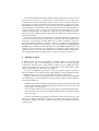
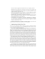
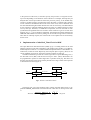
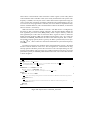
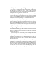
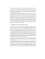
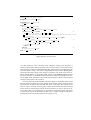
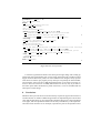
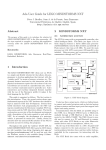
Implementing Ada.Real_Time.Clock and Absolute
Delays in Real-Time Kernels
Juan Zamorano 1, José F. Ruiz2 , and Juan A. de la Puente2
1
Departamento de Arquitectura y Tecnología de Sistemas Informáticos
Universidad Politécnica de Madrid, E-28660 Madrid, Spain
2 Departamento de Ingeniería de Sistemas Telemáticos
Universidad Politécnica de Madrid, E-28040 Madrid, Spain
[email protected] [email protected] [email protected]
Abstract. A real-time kernel providing multitasking and timing services is a fundamental component of any real-time system. Timing services, which are crucial
to the correct execution of this kind of applications, are usually provided by a
real-time clock and timer manager, which is part of the kernel and implements
the required functionality on top of the one or more hardware timers. Kernel
timing services must be implemented carefully in order to avoid race problems
and inconsistencies which may be caused by the fact that many common hardware timer chips are not intended at a direct implementation of software timing
services. This paper provides advice on the implementation of two of the Ada
timing services: Ada.Real_Time.Clock, and absolute delays (delay until). The example implementation of both services in the Open Ravenscar Kernel, which is
based on the ideas presented in the paper, is also described.
1 Introduction
Real-time systems are required to react to external signals within specified time intervals [18]. These systems are often built as a set of concurrent periodic and sporadic
tasks, implemented on top of a real-time kernel that provides multitasking and timing services, among others. The Ada 95 language [1] supports tasking and real-time at
the programming language level, thus providing appropriate high-level abstractions for
real-time applications. Tasking and timing constructs are usually implemented by an
Ada run-time system, which is built on top of a general-purpose operating system or, as
it is customary for real-time systems, a real-time kernel [4].
Ada 95 provides two kinds of timing services. The core language includes the
Ada.Calendar package, where a Time type and a time-of-the-day Clock function are defined [1, ch. 9]. The real-time systems annex [1, Annex D] defines the Ada.Real_Time
package, with more appropriate definitions of Time and Clock for real-time systems.
In the following, we will concentrate on the timing facilities defined in Ada.Real_Time ,
together with the absolute delay statement (delay until), as these are the ones most likely
to be used by real-time applications (and the only ones supported in the Ravenscar profile [3]).
This work has been funded by ESA/ESTEC contract no. No.13863/99/NL/MV.
Ada 95 timing facilities are usually implemented by some parts of the Ada run-time
system, which in turn relies on kernel services. These kernel services are built on top
of different kinds of clock and timer hardware devices, which are usually based on a
high-frequency oscillator which feeds a frequency divider counting register set. The kernel implementation of timing services has to be both accurate and efficient, providing
low granularity time measurements and delays together with a low overhead operation.
These properties are often in conflict when using commercial hardware timers, which
requires a careful design to be carried out in order to prevent race conditions, inconsistencies, and other problems that may compromise the performance and correctness of
real-time applications.
In the rest of the paper we provide advice on the implementation of kernel services for Ada real-time facilities, based on our experience with the Open Ravenscar
Kernel [5], an open-source real-time kernel for the GNAT compilation system targeted to the ERC32 (SPARC 7) architecture. Section 2 provides some background on
the operation of hardware timers. Section 3 gives some guidelines for implementing
Ada.Real_Time. Clock, and section 4 describes the current ORK implementation as an
example. Section 5 discusses some important issues related to accurate timer implementation, and sections 6 and 7 provide guidelines and implementation examples for
the Ada delay until statement. Finally, some conclusions are drawn in section 8.
2 Hardware timers
A hardware timer is a device which takes an oscillator signal as an input. In order
to operate with a range of clock frequencies, the input signal is usually fed through
a component called the scaler, which divides its frequency by a configurable integer
value. The resulting clock signal is used to decrement a down-count register, which
outputs a signal when its value reaches zero (figure 1).
The way of configuring a timer device is by writing into its registers, which have
their own addresses in the memory map of the computer. The timer registers can also
be read (for instance, to query the current value of the down-count register).
Hardware timers have several programmable operational modes, providing additional flexibility for the implementation of software timer modules. The most common
and important modes are:
– Periodic counter mode. In this operational mode, the initial value of the down-count
register is automatically reloaded by the hardware when the count reaches zero, and
then the down-count starts again.
– Interval counter mode. In this mode, the initial value is not reloaded when the downcount ends. Hence, the timer operation finishes and the down-count register remains
with a zero value.
The level of the output signal changes every time the down-count reaches zero. The
output pin is usually connected to a computer line, and the role of the timer device in
the computer depends on the line to which the output is connected and the operational
mode selected.
The most common configurations of hardware timers in a computer system are:
– Watchdog timer. The output pin is connected to the reset line of the computer, and
the device is programmed as an interval counter. As a result, the computer is reset
whenever the down-count reaches zero.
– Periodic timer. The output pin is connected to an interrupt request line, and the
device is programmed as a periodic counter. As a result, an interrupt request is
periodically generated every time the down-count reaches zero.
– Single-shot timer. The output pin is connected to an interrupt request line, and the
device is programmed as an interval counter. As a result, an interrupt request is
generated when the down-count reaches zero.
– Sound generator. The output pin is connected to a loudspeaker or a similar device, and the device is programmed as a periodic counter. By properly adjusting
the scaler and down-count preset values, the output signal changes at an audible
frequency, thus producing a sound.
Although watchdog timers are common in real-time systems, only periodic and
single-shot timers are relevant from the point of view of this paper.
3 Implementing Ada.Real_Time.Clock
Annex D of the Ada Language Reference Manual [1] requires a maximum resolution
of 1 ms and a minimum range of 50 years for Ada.Real_Time.Time. Therefore, at least
41 bits are needed to implement this data type.
An easy way to implement Ada.Real_Time.Clock would be to use a hardware periodic timer with a period equal to the required resolution. Unfortunately, the down-count
registers of most hardware timers are at most 32 bits wide (8 and 16 bits are the most
common sizes), which means that in most cases Ada.Real_Time.Clock cannot be implemented directly in hardware. However, it is possible to use a hardware periodic timer to
store only the least significant part of the clock value, while the most significant part of
the same value is stored in main memory, and incremented by the timer interrupt handler. Since the timer down-count is automatically restarted by the hardware, the clock
resolution is given by the scaled oscillator frequency. The interrupt period can be much
longer (actually up to the down-count register capacity) without loss of precision.
This method makes it possible to implement Ada.Real_Time.Clock with the required
resolution and range. However, there is a consistency problem (race condition), as reading the clock is not an atomic operation. Incorrect clock values may be obtained if an
interrupt occurs between the reading of the hardware and software components of the
time. The order of magnitude of the error is about one interrupt period, which should
be considered unacceptable. It must be noticed that masking the timer interrupt does
not solve the problem, because the down-count register is automatically reloaded by
the hardware when it reaches zero, even if interrupts are disabled.
It is also possible to use a single-shot hardware timer. In this case, the down-count
register is reloaded by the interrupt handler, and the consistency problem can be solved
by masking the timer interrupt in order to make the reading of both components of the
clock an atomic operation. However, this method introduces another problem related
to the precision of the clock, as the time spent by the processor to recognize an interrupt varies depending on the behavior of the software. For example, interrupts may be
delayed after a kernel procedure has raised the processor priority, or the handler may
execute a variable sequence of instructions before the timer is restarted. This variation
in time introduces an additional drift in the value of the clock, which is different from
the usual manufacturing drift which deviates the clock in a linear way. The drift induced
by the variation in interrupt handling changes the clock in a different amount of time
at every interrupt. Therefore, it is difficult to compensate, and even the kind of clock
synchronization algorithms that can be used in other situations to get an accurate time
keeping (see, e.g. [11]) are harder to implement. It should be noticed that, although the
additional drift could be overcome by taking into account the average time to restart the
timer after an interrupt request, this would result in a acceptable loss of monotonicity
for the clock.
4 Implementation of Ada.Real_Time.Clock in ORK
The Open Ravenscar Real-Time Kernel (ORK) [5, 6] is a tasking kernel for the Ada
language which provides full conformance with the Ravenscar profile [3] on ERC32based computers. ERC32 is a radiation-hardened implementation of the SPARC V7
architecture, which has been adopted by the European Space Agency (ESA) as the
current standard processor for spacecraft on-board computer systems [8].
The ERC32 hardware provides two timers (apart from a special Watchdog timer):
the Real-Time Clock (RTC) and the General Purpose Timer (GPT). Both timers can
be programmed to operate in either single-shot or periodic mode [19]. The timers are
driven by the internal system clock, and they include a two-stage counter which operates
as described in section 2 (figure 1).
Scaler Preload
Counter Preload
8 bits
SYSCLK
Scaler
32 bits
Zero indication
Counter
Interrupt
Control (Enable, Load, Reload, Hold, Stop at zero)
Fig. 1. Structure of the ERC32 timers.
The kernel uses one of the hardware timers, namely the Real-Time Clock, to implement Ada.Real_Time.Clock. The maximum time value that can be kept in the RTC
is:
RTCC 1 RTCS 1 232 28
MaxTime 109_951s
SY SCLK
107 where RTCC is the maximum value of the RTC counter register (32 bits wide), RTCS
is the maximum value of the RTC scaler (8 bits wide), and SYSCLK is the system clock
frequency (10 MHz). Not only this value is much shorter than required time range (50
years), but the clock resolution provided by a hardware-only implementation (25.6 µs)
is too coarse for many applications. Therefore, the clock cannot be implemented only
with the available hardware, and a mixed hardware-software mechanism, as discussed
above in section 3, is necessary.
ORK uses the first of the methods in section 3. The RTC device is configured by
the kernel so that it generates periodic interrupts. The interrupt handler updates the
most significant part of the clock (MSP_Clock), which is kept in memory, while the
least significant part of the clock is held in the RTCC register. In order to obtain the
highest possible resolution, ORK sets the RTCS preload value to zero. As a result, the
resolution of Ada.Real_Time.Clock is the same as the SYSCLK period, that is 100 ns.
The periodic interrupt period (which is given by the RTCC preload value) can be up to
429 s ( 232 107 ). These values are valid for the usual ERC32 system clock frequency
of 10 MHz.
In order to prevent the race condition which was mentioned in section 3, the Clock
function reads the hardware clock twice. This arrangement is valid because the long
interrupt period of the RTC prevents the occurrence of two interrupts during two consecutive clock readings. This solves the race condition problem, at the price of a slight
performance penalty in Ada.Real_Time.Clock function calls. The code of this function
is shown in figure 2.
MSP Clock : Time := 0;
pragma Atomic (MSP Clock);
pragma Atomic (MSP Clock) is needed because MSP Clock
is updated by Clock Handler.
5
function Clock return Time is
Before, After : constant Time :=
MSP Clock + Time (Kernel.Peripherals.Read Clock);
begin
if After Before then
an interrupt may have occurred while Before was being built
return After;
else
an interrupt has occurred while After was being built
return Before;
end if;
end Clock;
Fig. 2. ORK implementation of Ada.Real_Time.Clock.
10
15
5 Using hardware timers to provide high resolution timing
It is very common to implement software timers based on the same periodic interrupt
timer that is used for the real-time clock (see, e.g. [14, 12]). In order to improve the
resolution of the software timers, the timer chip can be programmed to interrupt at a
higher frequency than strictly required for keeping the clock.
The problem with this approach is that the overhead due to interrupt handling may
raise to unacceptable levels for high frequency values. Actually, interrupts need to be
programmed only when there is some timing event that has to be signaled. The key point
is that, even when a microsecond resolution is required, there is no need to have timing
events every microsecond. What is needed is a mechanism by which timer interrupts
are allowed to occur at any microsecond, but not necessarily every microsecond.
Single-shot timers provide just the right kind of support for this behavior, where
interrupts are generated on demand, and not periodically. However, this kind of devices
are not appropriate for implementing a monotonic, precise clock (see section 3). Therefore, the best arrangement is to use two hardware timers: a periodic interrupt timer for
the high resolution clock, and a single-shot timer for software timers. The single-shot
timer is reprogrammed on demand every time an alarm is set so that it interrupts when
the alarm expires. This arrangement provides high resolution software timers with a low
overhead. Many real-time kernels, such as RT-Linux [2], KURT [9], Linux/RK [15],
JTK [16], and ORK [5, 6] follow this approach.
6 Implementing absolute delays
The implementation of absolute delays (delay until in Ada) is based on software timers.
Timing events are kept in a delay queue ordered by expiration time. A single-shot timer
is programmed to interrupt at the expiration time of the first pending delay. When the
interrupt occurs, the first event is removed form the queue and the timer is programmed
for the next delay, and so on.
The best way to store delay expiration times is to use absolute time values. Otherwise, the timer interrupt routine would have to perform additional operations in order
to maintain the relative times of the events in the queue, which would increase the interrupt handling overhead and, even worse, the worst case execution time of the kernel
timing services. However, single-shot timers are programmed with relative times. This
means that the timer interrupt routine has to read the clock and subtract its value from
the absolute time of the next event, in order to compute the right preset value for the
timer down-count register.
It must be noticed that periodic timer interrupts must be enabled during the execution of the single-shot timer interrupt routine. Otherwise, the interrupt routine might get
an erroneous clock value if a periodic timer interrupt were pending. Such a situation
would result in an error of almost one periodic timer interrupt period in the single-shot
timer interval. The easiest way to prevent this kind of problems is to configure the timer
with the lowest interrupt priority as the single-shot timer, and the other one as the periodic timer. Some timer chips, however, cannot be configured in this way, which may
lead to very complex code in the timer interrupt routines. Luckily enough, the ERC32
timers have different priorities each, thus making this approach feasible for ORK.
The last point to be considered is the way to deal with delays which are longer than
the maximum time interval which can be programmed in the hardware timer. If only a
single-shot timer is used, the timer has to be restarted several times in order to get such
a long delay. Another possibility is to use both a single-shot and a periodic timer, in
such a way that the single-shot timer is only used when the next event expires before
the next periodic timer interrupt.
The first approach has only a small overhead, but raises the issue of how to model
the additional interrupts for response time analysis. On the other hand, the second approach may not work properly if the next event occurs before the next periodic timer
interrupt, but close to it. If the code which calculates the relative time for the next alarm
and programs the interval timer takes too long to execute, the single-shot timer can
actually be set to interrupt just a little bit after the next periodic timer interrupt. This
possibility has to be taken into account when coding the interrupt routines, as it may
give raise to race conditions resulting in alarms being lost or scheduled twice, depending on the actual implementation. However, there is a trivial solution, which is to record
the pending alarm status in a boolean flag. It must be noticed that this flag is also needed
by the low-level delay until procedure, because a current timer expiration may have to
be canceled by a new, but closer, delay request.
7 Implementation of absolute delays in ORK
Following the discussion of the previous section, the ORK implementation of absolute
delays is based on two timers: a periodic interrupt timer and a single-shot timer. The
first timer is the RTC, which is also used to support Ada.Real_Time.Clock (see section
3, and the second one is the ERC32 GPT, which is used to set alarms on demand. This
timer is only used when the next alarm is closer than the next periodic interrupt. A
boolean flag called Pending_Alarm is used to indicate that the single-shot timer is set.
As explained before, the RTC timer must have a higher interrupt priority than the
GPT. ORK allows the nesting of interrupts in the usual way: high priority interrupt
requests can preempt the execution of interrupt handlers with a lower priority, but lower
priority interrupts are masked during the execution of an interrupt handler. Therefore,
the periodic (RTC) interrupt handler can preempt the execution of the single-shot (GPT)
interrupt handler. On the other hand, single-shot timer interrupts are not recognized
during the execution of the periodic interrupter handler.
The kernel achieves mutual exclusion on its internal data structures (e.g. ready and
delay queues) by means of a monolithic monitor [13, 7], which is implemented by disabling interrupts, so that interrupt recognition is postponed while a kernel function is
being executed [17, 16].
The code of the RTC interrupt handler is shown in figure 3. The procedures Kernel.
Threads.Protection.Enter_Kernel and Kernel.Threads.Protection.Leave_Kernel change
the running priority in order to disable and restore interrupts for mutual exclusion, as
above described. The handler increments the most significant part of the monotonic
clock (MSP_Clock) with the clock interrupt period. The interrupt handler also checks
whether the alarm timer is set, which is recorded in Pending_Alarm, so that the current
alarm, if there is one, is not lost by setting a new one. More in detail, if the alarm timer
Pending Alarm : Boolean := False;
pragma Atomic (Pending Alarm);
procedure Clock Handler is
Next Alarm : Time;
5
begin
KP.Clear Clock Interrupt;
KT.Protection.Enter Kernel;
MSP Clock := MSP Clock + KPA.Clock Interrupt Period;
if not Pending Alarm then
10
Next Alarm := KT.Queues.Get Next Alarm Time;
if the head of the alarm queue is scheduled before the next clock
interrupt
if Next Alarm MSP Clock + KPA.Clock Interrupt Period then
set alarm
15
KP.Set Alarm (To Safe Timer Interval (Next Alarm MSP Clock Time (KP.Read Clock)));
Pending Alarm := True;
end if;
end if;
20
KT.Protection.Leave Kernel;
end Clock Handler;
Fig. 3. ORK RTC interrupt handler.
is set then nothing is done, as an alarm timer interrupt is coming soon. Otherwise, it
checks the alarm queue and sets the alarm timer if the next alarm is closer than the next
clock interrupt The function KT.Queues.Get_Next_Alarm_Time returns Time’Last when
the alarm queue is empty. The timer is programmed by the procedure KP.Set_Alarm,
which takes the relative delay to the alarm as a parameter. The clock value can be explicitly evaluated from its components (MSP_Clock + Time (KP.Read_Clock)) because
the clock interrupts are disabled during the execution of the clock handler. The function To_Safe_Timer_Interval is used to avoid possible negative values of the next alarm
caused by delays in the code execution.
The code of the alarm timer handler is shown in figure 4. The handler wakes up all
the tasks whose expiration times have already been reached. It then checks the alarm
queue and sets the alarm timer if needed. The clock is read again after waking up the
tasks in order to avoid an excessive jitter. It must be noticed that the alarm interrupt
priority must be restored (thus leaving the kernel monitor) in order to prevent an incorrect time value to be read because of a pending clock interrupt request. The kernel
is requested to execute the dispatching routine so as to enable a newly awaken task to
preempt the previously running task if it has a higher priority.
procedure Alarm Handler is
Now, Next Alarm : Time;
begin
Pending Alarm must be true
KP.Clear Alarm Interrupt;
5
Now := Clock;
KT.Protection.Enter Kernel;
while KT.Queues.Get Next Alarm Time = Now loop
extract the tasks that were waiting on the alarm
queue and insert them into the ready queue.
10
KT.Queues.Insert At Tail (KT.Queues.Extract First Alarm);
end loop;
Next Alarm := KT.Queues.Get Next Alarm Time;
the dispatcher is now called.
KT.Protection.Dispatch;
15
KT.Protection.Leave Kernel;
if the head of alarm queue is closer than the next clock interrupt
if Next Alarm MSP Clock + KPA.Clock Interrupt Period then
set alarm but read clock again to avoid an excessive jitter
KP.Set Alarm (To Safe Timer Interval (Next Alarm Clock));
20
else
Pending Alarm := False;
end if;
end Alarm Handler;
25
Fig. 4. ORK GPT interrupt handler.
It could be argued that the head of the alarm queue might change after waking up
all the tasks with expired alarms, but it can be easily shown that such a situation cannot
happen under the Ravenscar profile, for which ORK has been designed. Only sporadic
tasks which are waken up by higher priority interrupts can preempt the alarm handler,
and such tasks cannot execute a delay until statement due to the single invocation restriction. Since the execution of a delay until statement is the only way to put tasks in
the alarm queue under the Ravenscar profile restrictions, it can be concluded that the
alarm queue cannot change.
8 Conclusions
Hardware timers provide the low-level functionality required to support time features of
real-time kernels. A number of different approaches for implementing the Ada real-time
clock and absolute delays on top of this kind of hardware devices have been introduced
in the paper, and some problems related to the accuracy and efficiency of the implementation have been discussed. As an example, representative parts of the Open Ravenscar
Kernel implementation for ERC32 computers have been described in detail. Unfortunately, these solutions are not of general nature because of the diversity of timer device
arrangements in computers.
As we have shown, a hardware real-time clock provides the simplest and more efficient implementation of a clock. Unfortunately, this solution cannot be used with most
current hardware timers, which have only 32 bits or less. Timers with counting registers
up to 64 bits wide, such as the ones that can be found in Pentium processors [10], provide the required accuracy with an extended time range, and therefore are more suitable
for real-time applications. An advantage of hardware-only clocks is that there are no
race conditions or inconsistencies as the timer registers are read or written in an atomic
fashion.
An efficient and effective implementation of shared timers needs some help from the
software, though. It is not reasonable to force the hardware to maintain a list of pending
timers. Therefore, this function has to be provided by the software, with a hardware
support based on an efficient and a high resolution mechanism for programming timer
interrupts. This mechanism can be based on a single-shot interrupt timer with a 64 bit
counter.
Acknowledgments
The Open Ravenscar Real-Time Kernel was developed by a team of the Department
of Telematics Engineering, Technical University of Madrid (DIT/UPM), lead by Juan
Antonio de la Puente. The other members of the team were Juan Zamorano, José F.
Ruiz, Ramón Fernández, and Rodrigo García. Alejandro Alonso and Ángel Álvarez
acted as document and code reviewers, and contributed to the technical discussions
with many fruitful comments and suggestions. The same team developed the adapted
run-time packages that enable GNAT to work with ORK.
The ORK software was validated by Jesús Borruel and Juan Carlos Morcuende,
from Construcciones Aeronáuticas (CASA), Space Division. We also relied very much
on Andy Wellings and Alan Burns, of York University, for reviewing and discussions
about the Ravenscar profile and its implementation.
ORK was developed under contract with ESA, the European Space Agency. Jorge
Amador, Tullio Vardanega and Jean-Loup Terraillon provided many positive criticism
and contributed the user’s view during the development. The project was carried out
from September, 1999 to early June, 2000, with some extensions being made in the first
half of 2001.
References
1. Ada 95 Reference Manual: Language and Standard Libraries. International Standard
ANSI/ISO/IEC-8652:1995, 1995. Available from Springer-Verlag, LNCS no. 1246.
2. Michael Barabanov. A Linux-based real-time operating system. Master’s thesis, New Mexico Institute of Mining and Technology, June 1997. Available at http://www.rtlinux.
org/~baraban/thesis.
3. Alan Burns. The Ravenscar profile. Ada Letters, XIX(4):49–52, 1999.
4. Alan Burns and Andy J. Wellings. Real-Time Systems and Programming Languages.
Addison-Wesley, 2 edition, 1996.
5. Juan A. de la Puente, José F. Ruiz, and Juan Zamorano. An open Ravenscar real-time kernel
for GNAT. In Hubert B. Keller and Erhard Ploedereder, editors, Reliable Software Technologies — Ada-Europe 2000, number 1845 in LNCS, pages 5–15. Springer-Verlag, 2000.
6. Juan A. de la Puente, José F. Ruiz, Juan Zamorano, Rodrigo García, and Ramón FernándezMarina. ORK: An open source real-time kernel for on-board software systems. In DASIA
2000 - Data Systems in Aerospace, Montreal, Canada, May 2000.
7. Juan A. de la Puente, Juan Zamorano, José F. Ruiz, Ramón Fernández, and Rodrigo García.
The design and implementation of the Open Ravenscar Kernel. Ada Letters, XXI(1), March
2001. 10th International Real-Time Ada Workshop, Las Navas del Marqués, Ávila, Spain.
8. ESA.
32 Bit Microprocessor and Computer System Development, 1992.
Report
9848/92/NL/FM.
9. Robert Hill, Balaji Srinivasan, Shyam Pather, and Douglas Niehaus. Temporal resolution and
real-time extensions to Linux. Technical Report ITTC-FY98-TR-11510-03, Information and
Telecommunication Technology Center, Department of Electrical Engineering and Computer
Sciences, University of Kansas, June 1998.
10. Intel Corp. Survey of Pentium Processor Performance Monitoring Capabilities and
Tools, 1996. Available at http://developer.intel.com/software/idap/resources/
technical_collateral%/mmx/.
11. Hermann Kopetz. Clock synchronization in distributed real-time systems. IEEE Tr. on Software Engineering, 36(8), 1987.
12. Lynx Real-Time Systems, Inc. LynxOS Appplication Writer’s Guide, 1993.
13. A.K. Mok. The design of real-time programming systems based on process models. In IEEE
Real-Time Systems Symposium. IEEE Computer Society Press, 1984.
14. OAR. RTEMS SPARC Applications Supplement, 1997.
15. Shuichi Oikawa and Ragunathan Rajkumar. Linux/RK: A portable resource kernel in Linux.
IEEE Real-Time Systems Symposium Work-in-progress Session, December 1998.
16. José F. Ruiz and Jesús M. González-Barahona. Implementing a new low-level tasking support for the GNAT runtime system. In Michael González-Harbour and Juan A. de la Puente,
editors, Reliable Software Technologies — Ada-Europe’99, number 1622 in LNCS, pages
298–307. Springer-Verlag, 1999.
17. J.S. Snyder, D.B. Whalley, and T.P. Baker. Fast context switches: Compiler and architectural support for preemptive scheduling. Microprocessors and Microsystems, 19(1):35–42,
February 1995.
18. J.A. Stankovic. Misconceptions about real-time programming: A serious problem for nextgeneration systems. IEEE Computer, 21(10):10–19, 1988.
19. Temic/Matra Marconi Space. SPARC RT Memory Controller (MEC) User’s Manual, April
1997.