1
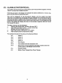
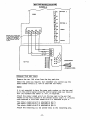
VA5000
VALET
Burglar Alarm
Installation
and
Operation Manual
INDEX
PtgeNo.
(A)
INTRODUCTION
1
(B)
FEATURES OF THE VA5000 CONTROL UNIT
2
(C)
DAILY OPERATING PROCEDURE
3
(D)
PROGRAMMING OF CONTROL UNITS
4
ACCESS CODE
5
CLOCK
5
HORN DURATION
5
ZONING
6
ENTRY/EXIT TIME DELAY
8
AUTO MODE
9
(E)
ALARM ACTIVATION RECALL
10
(F)
REMOTE KEYPAD
11
(G)
TELEPHONE DIALLER
12
(H)
RADIO'REMOTE CONTROL*
13
(I)
GENERAL NOTES
14
(J)
TROUBLESHOOTING
16
WIRING INSTRUCTIONS
17
(A) INTRODUCTION
The 'Valet* VA5000 is a versatile, highly sophisticated Burglar Alarm System
designed for ease of use and maximum efficiency. These operating instructions
describe the method of setting up and operating the System.
The System is controlled by the Master Control Unit, which is used to display the
current state of the system and is also used to enter and change information.
Information is entered on the Master Control Unit and checked on the display.
The various features of the VA5000 are as follows:
—
Micro Processor based control unit with memory analysis;
—
4 Digit Code Access;
—
Remote Keypad for the Front Door;
—
Zoning — ability to segregate different areas (Zones) so that parts of a home
can have detectors switched on while other areas are switched off;
—
Variable Entry/Exit Delay;
—
Variable Horn Time.
Options
—
Remote Control
An optional Hand Held Remote Control Unit is used to remotely switch the
VA5000 ON or OFF. This unit has the added feature of a PANIC button which
will set off an alarm immediately.
—
Telephone Dialler
An optional telephone dialler that will automatically dial three separate 'user
selected' telephone numbers in the event of an alarm.
(B) FEATURES OF THE VA5000 CONTROL UNIT
The VA5000 Control Panel is designed such that you can select and program into
the System the following information:
1.
Your own Access Code
You can choose and enter your own four (4) digit 'access code1. The code can
be changed at any time after first entering the initial access code.
2.
Clock
The System incorporates a clock which displays the time of day and is used
to:
(i)
Record the time of an alarm;
(ii)
Automatically turns the system ON or OFF if used in the 'auto mode'.
3.
Horn Duration
You can select the length of time that the horns will sound after the triggering
of an alarm. Please note — horn duration time is subject to local E.P.A. and
local By-Laws.
4.
Zoning
The system allows for the use of up to four (4) separate zones such that you
can select which zones or areas of the house you wish to be activated when
you 'arm' the system. Each detector can be programmed into one or several
zones to provide total flexibility with respect to the areas you wish to be
covered.
5.
Entry/Exit Time Delay
The system allows you to select the length of time that you require in order to
leave the home after 'arming' the system as well as the time you require to
enter the home and 'disarm1 the system. In addition, you can determine
which detectors you wish to be controlled by these delays, as distinct from
the detectors that you wish to be left programmed on 'instant'.
6.
Automatic Mode
While the system is normally 'armed* and 'disarmed* by entering a code at
either the Master Panel or the Push Button Keypad, the system can be
programmed to automatically turn itself ON and OFF at pre-set times each
day.
7.
Telephone Dialler
The optional Telephone Dialler can be programmed to ring up to three (3)
telephone numbers after activation of an alarm. The system will make six (6)
attempts in total at ringing (in sequence) three (3) telephone numbers.
These functions are selected by using the Push Buttons beneath the control
flap.
(C) DAILY OPERATING PROCEDURES
There are only two controls which are normally used on a day-to-day basis.
1.
Arm/Disarm
The system can be 'armed' or 'disarmed1 from either the remote keypad or
alternatively the VA5000 system control panel.
(i)
Remote Keypad
Enter the selected code (4 numbers). To 'arm' or 'disarm' simply enter
the four (4) digit code and the system will change from 'arm* to 'disarm'
or vice versa.
(ii)
Control Panel
Enter the four (4) digit code and push the 'armTdisarm' blue button.
2.
Zone Activation/Deactivation
If you wish to change the zones that are activated/deactivated:
(i)
Enter the access code — 4 numbers.
(Display will show 'GO'.)
(ii)
Push the activation/deactivation zone button.
(Display will show 'Zone'.)
(iii)
Push the appropriate zone number on the control panel, i.e. 1.2,3 or 4.
(Display will not change — zone will turn ON or OFF.)
(iv) Push 'O.K.* button — push 'Cancel' button.
Note: The remote 'arm'/'disarm' function is only used in conjunction with the
optional radio remote control. This radio remote control requires the
VA6000 'radio/wireless' master control unit.
The 'automatic mode'can be selected by pressing the 'Auto/Manual*
button under the lift-up flap.
(D) PROGRAMMING OF CONTROL UNITS
1.
PRE-PROGRAMMED SETTING
The VA5000 control unit has been designed such that as soon as the battery
is connected and the power turned on, the unit will automatically program
itself as follows: (N.B. Battery is to be connected before power turned on.)
(i)
Access Code
— 1.2,3 and 4
(ii)
Clock/Time
— 00:00
(iii)
Horn Duration
— 10 Minutes
(iv)
Zoning
— All detectors connected to
Zone 1 and Zone 1 activated.
(v)
Exit/Entry Delay — Exit delay 20 seconds.
Entry delay 20 seconds.
— All detectors included in the
exit/entry delay path.
(vi)
Automatic Mode — Set to Manual.
All of the above functions can be altered to suit your specific needs by
following the procedure detailed below.
2.
PROGRAMMING INSTRUCTIONS
The VA5000 Control Panel has been programmed such that the initial code is
'1234'. Prior to entering or changing any of the program functions, it is
necessary to first enter the selected four (4) digit code.
After entering the access code, the control panel will display the word 'GO'
which is an indication that you can proceed to change or enter any of the
functions or alternatively 'arm' or 'disarm1 the system.
The procedure for entering any of the program functions is to push the
relevant button behind the control flap, enter the information by use of the
keypad and then push the 'O.K.' button to lock the information into memory.
The clear button is used for removing information from the display or
memory.
The cancel button takes you out of the access mode which means that no
further information can be entered or changed without once again entering
your 4 digit code. After pushing the cancel button 'the time' will once again be
displayed.
Note: It is important that the re-chargeable battery is fully charged. In this
regard the system should not be 'armed* until 90 minutes after the unit
has been 'powered up', (i.e. Connected to the power supply.)
If you have trouble in the programming of any function, it is suggested
that you push the cancel button and 'start again'. Simply re-enter your
access code and recommence the entering of information as per
these instructions.
(i)
ACCESS CODE
After turning on the power unit for the first time, the unit will be set to
the code'12 3 4'.
In order to change your code:(a)
Enter the current code '123 4'. (Display will show 'GO'.)
(b)
Push change code button behind control flap.
(Display will show 'C C'.)
(c)
Enter your own access code by choosing 4 numbers and then
press the appropriate numbers on the keypad.
(Code will be shown on the display.)
(d)
Press 'O.K.* button to 'lock in' your selected code.
(Display will show 'GO'.)
(e)
You can now either press the cancel button and take yourself
out of 'access mode' or alternatively proceed to enter additional
information, i.e. Time, etc.
Note: If you press the cancel button you will need to re-enter
your access code prior to entering any further
information.
Note: If you wish to change your code at any time, simply enter
your current code and follow the above procedure.
(ii)
CLOCK
The control unit will initially display the time 00:00. The procedure to
set the time is as follows:
(a)
Enter access code. (Display will show 'GO'.)
(b)
Lift flap and press Time of Day' button. (Display will show T.)
(c)
Enter time by pressing appropriate numbers on keypad, e.g. if
the time is 2.30 p.m., press keys 1430, or if the time is 7.30 a.m.,
press keys 730.
(d)
Press 'O.K.' button. (Display will show 'GO'.)
(e)
Press cancel button — time of day will be displayed.
(iii)
HORN DURATION
The Horn Duration time is the length of time that you wish the horns to
sound after an alarm has been set off. The control unit has initially
been programmed such that the horns will sound for 10 minutes.
The horn duration time can be changed as follows:
(a)
Enter access code. (Display will show 'GO'.)
(b)
Press 'Horn Duration' button behind lift-up flap.
(Display will show'Hd'.)
(c)
Enter length of time by pressing the appropriate numbers on
the keypad, e.g. to enter 6 minutes and 25 seconds, push the
numbers 625.
(d)
Press 'O.K.* button to lock-in horn duration time.
(Display will show 'GO'.)
(e)
Press cancel button — time of day will be displayed.
Note: You can check your programmed horn duration time by
pushing the horn duration button underneath the control flap.
(iv)
ZONING
(a)
General
The detectors can be connected to any one of the 4 alternative
connection points at the rear of the control panel. These four
alternative connection points are called 'stations' and are
numbered 1,2,3 and 4.
The detector or detectors connected to each one of these
'stations' can be programmed into one or all of the 4 alternative
zones displayed on the front of the control panel.
We would suggest that all detectors should be included in Zone
1 and that this Zone is then used when you require the whole
house to be 'armed'.
The remaining zones can be used in circumstances in which
you wish to have part of the home 'armed' while other parts of
the home are 'disarmed', (e.g. At night you may wish to have the
bedroom area 'disarmed' while the living areas are 'armed'.)
You can select which detector [or groups of detectors] are
included in the various zones.
(b)
Pre-Programmlng
The control panel has initially been programmed such that all
stations [groups of detectors] are set into Zone 1 and Zone 1 is
activated.
(c)
Programming
In view of the fact that the system has automatically been
programmed as above, it will be necessary to remove from
Zone 1 any stations that are not connected to detectors. Unless
these stations are removed from Zone 1, an alarm condition will
result. To remove from Zone 1 the stations that are not
connected to a detector, proceed as follows:
1.
Enter Access Code. (Display will show 'GO'.}
2.
Press 'Station Set' key behind control flap.
(Display will show 'Zn'.)
3.
Press '1' on the keypad, (display will show 'ZnV)
indicating Zone 1.
4.
The display will then show the stations [detectors] that
are included In Zone 1. i.e. 'Zn 11' 'Zn 12' 'Zn 13' 'Zn 14'.
5.
To remove the stations not connected to a detector,
push the 'clear1 button followed by the 'O.K.1 button at
the time that the relevant station number is being
displayed.
In order to alter or change the programming of detectors into
the various zones, proceed as follows:
(a)
Enter access code. (Display will show 'GO'.)
(b)
Press 'Station Set' key behind control flap.
(Display will show 'Zn'.)
(c)
Example, press 2 on the keypad. (Display will show 'Zn 2'
— indicating Zone 2.)
(d)
Enter the stations [detectors] that you wish to place in
Zone 2, e.g. if you wish to include station 1 in Zone 2
push button '1'. (Display will show 'Zn 2 V.)
(e)
Push 'O.K.' button. (Display will show 'Zn 2'.)
(f)
Push button 2 to enter station 2 into Zone 2.
(Display will show 'Zn 2 2'.)
(g)
Push 'O.K.' button. (Display will show 'Zn 2'.)
(h)
Repeat procedure to.enter the various stations [groups
of detectors] that you require to be entered into Zones.
(i)
Push 'cancel' button — time of day will be displayed.
(j)
You can check your programmed zoning by pushing the
'station set' button underneath the control flap followed
by number 'V (for Zone 1). number '2' (for Zone 2),
number '3' (for Zone 3), number '4' (for Zone 4).
The stations programmed into the various zones will be
displayed.
(v)
ENTRY/EXIT TIME DELAY
(a)
General
The system allows you to determine the length of time that you
require in order to leave the home after arming the system and
enter the home prior to disarming the system, i.e. An exit delay
of 45 seconds will allow 45 seconds in which to leave the home
without causing an alarm. In addition, you can select which
stations [groups of detectorsl you would like to be covered by
the entry/exit delay (entry/exit delay path) as distinct from
those stations|groups of detectors] that you would prefer to be
on 'instant', i.e. No delay.
(b)
Pre-Programming
The system has initially been programmed to provide you with
a 20 second entry delay and a 20 second exit delay and in
addition, all stations [detectors] have been programmed to be
covered by these entry/exit delays.
(c)
Programming
The procedure for changing the entry/exit delay times and/or
the entry/exit delay path is as follows:
1.
Enter access code. (Display will show 'GO'.)
2.
Press exit/entry button — under lift up flap.
(Display will show'IN'.)
3.
Enter required entry delay time e.g. 30 seconds.
(Display will show '0030'.)
4.
Press 'O.K.' button to 'lock in' entry delay.
(Display will show 'OUT'.)
5.
Enter required exit delay time e.g. 30 seconds.
(Display will show '0030'.)
6.
Press 'O.K.' button to 'lock in' exit delay.
(Display will show 'EE'.)
7.
The 'EE' is the symbol for the entry/exit delay path. i.e.
The detectors that you wish to be covered by the above
delays.
8.
Enter stations [groups of detectors] that you require to
be on the entry/exit delay path e.g.
— Enter number '1' for 'station number 1'.
(Display will show'EEV.)
—
9.
10.
Push 'O.K.' button. (Display will show 'EE'.)
Enter any additional stations, i.e. '2,3 or 4' that you wish
to be included in the entry/exit delay path.
After entering the required stations [groups of detectors] in the entry/exit delay path, press 'cancel' button to
restore time of day.
(d)
Clearing Detectors from Entry/Exit Delay Path
If you wish to remove some of the stations [groups of detectors]
from the entry/exit delay path, proceed as follows:
1.
Enter access code. (Display will show'GO'.)
2.
Press entry/exit button — under lift up flap.
(Display will show the time.)
3.
Push 'O.K.' button. (Display will show 'OUT.)
4.
Push 'O.K.' button. (Display will show the various stations
[groups of detectors] in the delay path.
5.
To remove stations, simply push the 'clear* button,
followed by the 'O.K.' button while the station is
displayed.
6.
Push 'O.K.' button to restore the time of day.
Note: You can check your programmed entry/exit delay path
by pushing 'entry/exit delay' button underneath the
control flap.
Push 'O.K.' button. (Display will show 'IN'.)
Push 'O.K.' button. (Display will show 'OUT'.)
Push 'O.K.' button. (Display will show 'EE1'.)
e.g. Station'1*.
Display will show in turn the entry delay, exit delay and
the stations included in the entry/exit delay path.
(vi)
AUTOMATIC MODE
The 'Automatic Mode* enables you to program the system such that it
automatically 'arms' and disarms* itself at pre-set times, e.g. if all the
family are away from the home for a set period each day, the 'automatic
mode' can be used to automatically 'arm' and 'disarm' the system at
pre-set times on a daily basis.
(a)
Enter access code. (Display will show 'GO'.)
(b)
Press Time ON/OFF button behind lift up flap.
(Display will show Tn'.)
(c)
Using the keypad enter the time you wish the system to turn on
[arm] itself, e.g. if the system is to be armed at 9.30 a.m., the
numbers 930 should be pressed.
(Display will show Tn 930'.)
(d)
Press 'O.K.' button. (Display will show Tf [for time off].)
(e)
Enter the time that you require the system to 'turn off' [disarm]
automatically, e.g. if you wish the system to be disarmed at 4.30
p.m., enter the numbers 1630.
(Display will show Tf 1630'.)
(f)
Press 'O.K.' button. (Display will show 'GO'.)
(g)
Push cancel button — time of day will be displayed.
The 'turn on' [arm] and 'turn off [disarm] times have now been set.
The 'automatic mode' can be selected by entering your 'access code'
and pressing the 'Auto/Manual' button under the lift up flap.
(E) ALARM ACTIVATION RECALL
The system will record the time of day that an alarm was activated together with the
'station' number that initiated the alarm.
Following an alarm, the display will indicate the station [detector] or circuit, (e.g.
panic circuit) that has caused the alarm.
This will be displayed on the fluorescent display until the system has been
'disarmed'. Once disarmed, the display will again indicate the normal time of day but
the time of the alarm, together wfth the cause of the alarm, can be recalled by simply
pushing the 'alarm activation* button behind the control flap. On the pushing of this
button, the system will display the time of the last alarm together with the 'circuit'
that caused the alarm.
The alarm memory can be cleared by:
1.
Entering the access code. (Display will show 'GO'.)
2.
Push 'alarm activation' button — under control flap.
(Display will show details of alarm.)
3.
Push 'clear1 button, followed by 'O.K.' button.
4.
Push 'cancel' button to restore time of day.
The symbols for each of the various circuits are as follows:
AL1
Station 1
AL2
Station 2
AL3
Station 3
AL4
Station 4
ALP
Panic Button
ALH
Horn cables have been tampered with.
ALA
More than 3 incorrect attempts have been made to enter the
'access code' on the Master Control Panel.
ALL
Keypad Tamper.
ALt
Battery Cover Tamper/Horn Cover Tamper.
10
(F)
REMOTE KEYPAD
The VA5000 system includes a remote keypad which can be used to 'arm' and
'disarm* the system. The remote keypad is normally located inside the home but
adjacent to the front or back door. The remote keypad also incorporates a 'panic'
button facility and can also be located in a bedroom and used to 'arm' and 'disarm'
the system as well as act as a panic facility. To activate the panic button from the
keyboard, push two blue buttons simultaneously. The remote keypad is operated
by a four (4) digit code which can be selected and changed as follows:
REFER KEY PAD WIRING DIAGRAM FOR CODING
11
(G) TELEPHONE DIALLER (Optional)
A telephone dialler can be added to the basic VA5000 such that the system will upon
activation of an alarm automatically dial up to three telephone numbers. You can
enter and change these telephone numbers at any time.
The system will make six attempts in total at 'dialling' the three telephone numbers
in sequence.
The telephone dialler can be used to either telephone a friend, e.g. neighbour or
family; your office; a pager; or a security organisation. A unique telephone code can
be used so that a Security Agency can identify the source of a telephonealarm. This=
code will generally be issued by the Security Agency and may comprise up to six
digits.
Please note: There are several alternative 'coding systems' and the equipment used
by some Security Agencies may not be compatible with the Valet
system.
To program telephone numbers:
(i)
Enter access code (4 numbers). (Display will show 'GO'.)
(ii)
Press [Phone No.] button behind flap. (Display will show 'Ph'.)
(iii)
(iv)
Press '1' on the keypad (for Phone No. 1).
Press the numbers on the keypad for required telephone number, e.g.
5613722. (Press 'O.K.' button — display will show 'GO'.)
(v)
To enter a second telephone number, press 'Phone No.1 button and number
2, and then enter the required telephone number as above.
(vi)
Repeat for third telephone number.
(Note: In order to enter a STD number, a hyphen (-) must be inserted after the
STD Area Code, e.g. 02 - 6484488.)
12
(H) RADIO 'REMOTE CONTROL'
A radio or wireless system is available as an alternative to the standard VA5000
system. This VA6000 system allows you the following feature.
The system can be 'armed' and 'disarmed* by the use of a Hand Held Remote
Control Unit that can be carried in a handbag, brief case or in the car.
The system can be 'armed' and 'disarmed' from outside your home and as such you
do not require any exit/entry delay and all detectors can be on 'instant alarm*.
In addition, you do not have to enter your 'access code' each time you wish to 'arm*
or 'disarm* the system.
The Hand Held Remote Control also includes a 'panic' bunon that enables you to
activate an alarm by the push of a button.
The Radio 'Remote Control' feature incorporates 'digital coding*.
13
(I)
GENERAL NOTES
1.
Access Code
No function can be changed without first entering your selected access code.
2.
Keypad
The keypad is used to enter information into the system.
3.
Cancel Key
The cancel key must always be pressed after information has been entered
and to remove the system from 'access mode', i.e. to make the system
inoperable without entry of the 'access code'.
4.
Clear Key
The 'clear' key is used when incorrect information has been entered.
5.
O.K. Key
The 'O.K.* key is used to 'lock in' information that has been entered/displayed.
When pressed, the display will show 'GO' enabling you to enter further
functions or push 'cancel' to revert back to the time of day.
6.
Hyphen (-) Key
The (-) is used when entering STD telephone numbers.
7.
Error
If the display shows the word 'error' this means that an incorrect entry has
been made — simply press the 'cancel' key and the display will revert to 'GO*.
You can either continue with programming or press 'cancel* button to revert
to time of day.
8.
Forgotten Access Code
If you forget your access code:
(a)
Disconnect telephone plug if telephone dialler is installed.
(b)
Turn off power at the power point and remove the 210V
3 pin plug.
(c)
Open battery cover and disconnect battery - note horns
will sound after battery cover has been opened and before
battery has been disconnected.
(d)
Walt 30 seconds then re-connect battery.
(e)
Re-connect telephone (if applicable)
(f)
Turn power back on
(g)
Display will show 00.00
(h)
Re-enter all information into the memory as per the
operating instructions remembering that access code 1234
will be automatically in the memory.
-11-
9.
Changing the Battery
The internal battery, used to power the system during a powerfailure, slowly
loses capacity and should be replaced every two or three years.
To replace the battery, the battery cover must be removed and this will set off
the alarm. To reduce the inconvenience caused by the alarm, (e.g. to stop the
horn sounding) firstly disconnect the power supply (transformer) and then
the telephone plug (if attached) should be removed and the horn duration set
to zero.
To change the internal battery, the following procedure should be adopted:
(a)
(b)
(c)
(d)
(e)
(f)
(g)
(h)
(i)
(j)
Enter Access Code.
Set horn duration time to Zero by pressing 'Horn Duration' button, and
Zero time.
Press 'O.K.'
If a telephone dialler is fitted, remove telephone plug from socket.
Turn off power. Disconnect the power supply.
Open battery cover and replace battery, making sure that the RED
wire is connected to battery '+ve' terminal.
Close battery cover.
Re-connect telephone dialler plug.
Re-connect power supply.
Refer to programming functions for re-programming.
is
(J)
TROUBLE SHOOTING
During normal operation and In setting up the system, a few problems can arise
which may cause you to think the system is faulty. Below is listed a number of
common problems which may occur and which can be easily fixed.
False Alarms
False alarms can be caused in a number of ways and can be broken up into groups.
First, check the display to see what type of alarm it is:
(1)
ALH Alarm
Check the following:
—
Horn wires shorted, cut or broken.
(2)
ALt Alarm
—
Check battery cover tamper switch and horn cover tamper switch.
(3)
AL1 to AL 4 Alarm (Wired Detectors)
Check the following:
(i)
Wires to detectors are shorted, cut or broken,
(ii)
Detector has terminating resistor (see Installation procedure),
(iii)
Detector is operating correctly (see Installation procedure),
(iv)
All stations are in correct zones.
(4)
AL L Alarm
—
Check keypad tamper switch.
Alarm will not Operate
Check the following:
(1)
Horn duration is not set to zero.
(2)
All stations are in correct zones.
(3)
All radio linked detectors are set up to correct station number.
(4)
Detectors are operating correctly.
(5)
If telephone dialler option is fitted, check that telephone numbers are correct
and that telephone plug is installed.
(6)
Master control unit is set to 'armed'.
(7)
Zones are activated.
(8)
Flashing Zone lights — probable error in zone/station programming, e.g.
could be caused by programming into a zone/station that is not connected to
a detector.
16
(BURGLAR ALARM SYSTEM
WIRING SCHEMATIC FOR MODEL VA 5000
Diagram 1
VA5000
SECURITY
CONTROLBOX
Transformer
3 Pin Plug
(240 volt)
Internal Siren
"*
'
External Siren (In Siren Cover) and Tamper Switch
\\\°l Strobe Light
Passive Infra-red
Detector
Passive Infra-red
Detector
000
ODD
oaa
ooa
Coded Key Pad
Option/s
Reed switches, remote panic switches, smoke and breaking glass detectors.
Optional Telephone Dialler
to Telecom 611 Mode 3 socket
see page 12 for details
//,/y
4 core shielded security cable
3 par telephone cable
(2 metres of cable and socket are provided with the
master station)
17
VA5000 BURGLAR ALARM SYSTEM
CONNECTION/TERMINATION OF ALL WIRING
Having completed all necessary wiring as per schematic Diagram 1 the next step is to terminate those
wires at the Master Unit, detection devices, sound alarms and options.
FOR CONNECTION AT MASTER UNIT PROCEED AS FOLLOWS
1.
2.
a
4.
5.
6.
7.
a
For P.I.R. Detectors
Connect as shown on Diagram 2
For Internal Horn
Connect wire as per Diagram 2 to terminals 21 and 22 and to horn, as shown.
For the External Horn with Horn cover and Tamper Switch
Firstly remove the resistor from terminals 3 and 4 by loosening screws. Connect the WHITE and BLUE
wires to these terminals (i A 3 and 4) and the RED »nd BLACK wires to terminals 19 and 20.
At the Horn
Connect the RED and BLACK wires to the two (2) leads coming from the horn and the BLUE and
WH ITE wires to the two (2) terminals of the tamper switch.
For the Strobe
Connect as shown as Diagram 2 to terminals 5 and fi.
For the Key Pad
Connect as shown on Diagram 4.
For the Battery
Firstly remove the battery cover from the Master Unit, as shown on Diagram.
Connect the RED lead inside the Master to the RED terminal on the battery (4-).
Connect the BLACK lead inside the Master to the BLACK terminal on the battery (-).
Place battery inside the Master and replace cover.
For Power Into the Master
Connect the four (4) coloured wires from the Transformer to the AC Terminals, as shown on Diagram
2. Do not turn power on at this time.
For Connection at the P.I.R. Detectors
Connect the Security cable, as shown on Diagram a
a
Insert 3 pin plug from Transformer into power point.
OPTIONS
10. Reed Switches. Remote Panic Buttons. Smoke and Breaking Glass Detectors.
Consult your authorised Valet Distributor for the necessary connection diagrams.
[WARNING]
ANY DETECTORS OTHER THAN THOSE SUPPLIED BY VALET REQUIRE
MODIFICATION BEFORE BEING COMPATIBLE WITH THE VA5000 CONTROL
• f\N t L.
-18-
WARNING
PRIOR TO CONNECTING ANY WIRING TO THE CONTROL PANEL, DETECTORS,
KEYPADS, HORNS, STROBE LIGHT ETC ENSURE THAT THE POWER IS TURNED OFF
AND THE BATTERY DISCONNECTED.
FAILURE TO DO SO WILL CAUSE DAMAGE TO YOUR SYSTEM AND VOID THE
WARRANTY
it BEFORE TURNING THE SYSTEM ON:—
1. CONNECT THE BATTERY FIRST, REPLACE THE BATTERY COVER AND
2. TURN THE POWER ON AT THE POWER POINT.
IT IS ESSENTIAL THAT THIS SEQUENCE BE FOLLOWED WHENEVER ALL POWER IS
REMOVED FROM THE SYSTEM FOR WHATEVER REASON.
19
[VALET VA5000 BURGLAR ALARM WIRING DIAGRAM]
DIAGRAM 2
TO CONTROL UNIT CONNECTOR
^
m
<-—
1
FRANSFORMEI
BLUE
1
WHITE-i
^,^-REp—.
^ =ai
1
;;
1
1
*..
0 2
J!
L_
t!2v Battery
Ov
3
PANIC
.
i "w—./
.|
PIR DETECTOR
au
i
>
DLUL
REP
BLACK
9
V K.-JVUVIX VE ^ 1 ^
STROBE
/V
BLUE
V.WH1TE
¥
BLAC
7
,S*
<X
RE
rn-r
p
BLUE
11
1
i
I
WHITE-J:
n
ii
i
I
*f=^s"
^
J
.
i
ii
i
4K7
'
RESISTOR!^
m IIP—.
1
WHIIt-i1
1
„,--.,__
J
n
4 8
ri
1 1
STATION 1
STRC
LIGH
9
10
1
'
1
|
•1p-rS-~
.
h ^ \D
IM^^^HH
.
.K?
j
RESISTOR II
n
-e
11
STATION 2
12
TTTT
f
^
rtLiJc
:!
DuUL
t
/
— WHIT^:
1 ]
- c===f^ '
•JTT
.
n
,K7
5
RESISTOR
o
"" WHITi
|=^ ~^f[\
l^ r-|l
I~^-^,
*~~B
J
V*~
«,
fl
11
^-
I
•.
1
j§
i
— *^
,
'
R,
J
H-i
STATIONS .
^
r
17
STATION**
18
HORN 1
« 20
BLACK.
DUJ-«( n
16
o" 19
-RFD
.
^
0 21
-^
-^
22
ni ••=
''^--^
JJ
^V
-ULUE
WHITE
L...ECJlftO
[IMPORTANT]
^
P
It.TERNAL H O R N / ^ - ^ f i ^ <
ii
e
rS
RESISTOR! 1
E XTERNAL HOP 1<||*""~"^v. i!
II
1*
15
S
WH 1 1 k •-— ——-— --JUJ, L.-,»«Ms««c»*.r4
f^=
—Jl'S
HORN COVER WITH
TAMPFR SWITCH
i'" •
l>
BLUE
HIUF
13
1
N
HORN 2
.VALET
Any excess wiring other than the red. black, white or blue wires must be
trimmed back so as to avoid contact with other wiring.
-20-
P.I.R. DETECTOR WIRING
DIAGRAM 3
PIWCM HOU IN
DCTCCTO* HOUSING
AMG VKIMC CABLE
THIIOUCN BACK OF
OCTtCTO*
SYSTEMS WITH, FROM FIVE (5) TO EIGHT (8) P.I.R. DETECTORS!
When wiring in
terminate
a)
b)
c)
d)
the 5th detector at the Control Panel to STATION 1
the red wire onto terminal 1
the black wire onto terminal 2
the blue wire onto terminal 8
the white wire onto terminal 9
REMOVE THE «K7 RESISTOR FROM TERMINALS 8 and 9 ONLY.
When installing additional detectors six (6) to eight (8) repeat the
wiring procedure as for detectors two (2) to four (4)
eg.
Detector (6) in series with detector two (2) on STATION 2
terminating
a)
b)
c)
d)
the
the
the
the
red wire onto terminal 1
black wire onto terminal 2
blue wire onto TERMINAL 11
white wire onto terminal 12
and remove the 4K7 resistor from terminals
11 &
12.
[SYSTEMS WITH, MORE THAN EIGHT (8) P.I.R. DETECTORSJ
Consult your authorised Valet dealer for special wiring instructions.
ISYSTEMS WHERE NO KEY PAD is TO BE INSTALLED]
A link must be inserted between terminals 24 and 26 which can be
found in the kit.
-21-
KEY PAD WIRING DIAGRAM
DIAGRAM 4
STATION 4
•*••*,
i>r /
>3 :24
26
2
M 6f / 1P / l
Should your system have
• link between terminals
21 and 26 it should be '
removed if a key pad is
to be installed with the
system.
HORN1
««.
3
/
x^
0 19
0
|
20
»••*,
^
0 21
--*
.0 22
1
HORN 2
....
""N
f
•\
—RED
•^1
•BLACK
T2
BLUET3
WHITE,, - •rn.fi
•MUM
/
•\
'.
/
*
>r ;
CODED WIRES
KEY PAD
JOINED SIX WIRES
CODING THE KEY PAD
Remove the ten (10) wires from the key pad pins
Select the code you require, but remember you cannot use the
same number twice (i.e. 1241 or 5357 will not work)
NOTE
it is not essential to have the same code number on the key pad
as on the control panel since the control panel code can have all
four (4) numbers the same i.e. 7777, if required.
Attach the colour coded wire A on the key pad to the pin that
relates to the first number of the chosen access code i.e. if access
code selected is 4579 then coded wire A is attached to pin 4.
The colour coded wire B is attached to pin 5.
The colour coded wire C is attached to pin 7.
The colour coded wire D is attached to pin 9.
Attach the remaining six (6) joined wires to the remaining pins.
-22-