1
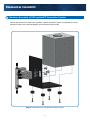
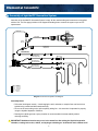
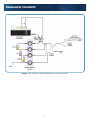
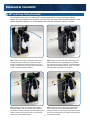
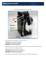
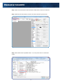
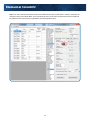
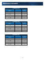
Elemental Scientific
HG-MP2-4-A hydrideICP Generation System
hydrideICP Hydride Generation System
User Manual
MP2 hydrideICP Generation System
Elemental Scientific
1500 North 24th Street
Omaha, NE 68110 USA
Phone: 1.402.991.7800
Fax: 1.402.991.7799
Email: [email protected]
Web: www.icpms.com
1
Elemental Scientific
1 Instructions
The ESI hydrideICP Generation System is used to concentrate hydride forming elements before analysis
with an ICP based spectrometer. By increasing the concentration, the sensitivity of the ICP spectrometer
increase for these elements. This manual explains the use and setup of the ESI hydrideICP Hydride
Generation system.
Parts Included with the ESI hydrideICP Hydride Generation System:
•
•
•
•
•
•
•
•
•
•
•
•
•
•
•
•
•
•
•
•
•
•
1 quartz Hydride Separation Chamber (assembled)
1 PFA Hydride Mixing Tee (assembled)
1 mounting bracket (assembled)
1 Bag of Black-Black Tygon tubing
1 Bag of Orange-Yellow Tygon tubing
1 Bag of Orange-Green Tygon tubing
1 Bag of Blue-Yellow Tygon tubing
2 CTFE cups (pre-assembled)
3 M5X10 PEAK mounting screws (pre-assembled)
4 Teflon Coated M3X10 Mounting Screws (pre-assembled)
4 SBR Rubber Feet (pre-assembled)
6 Barbed Male Unions
1 Barbed Female Union
1 Yellow Capillary Connection Line
1 Blue Capillary Connection Line
1 Argon Gas Line Kit
1 1/4-28 Nebulizer Nut Adapter
1 4-Channel MP2 Peristaltic Pump(assembled)
3 Sample Probes
ESI SC Software
USB Peripump Communication Cable
MP2 Power Cable With Adapters
2
Elemental Scientific
2 Hardware Assembly of ESI hydrideICP Generation System
Should repairs need to be made to the hydrideICP Hydride Generation System, an exploded view of the
assembly is shown in the following diagram. All screws have Phillips heads.
Diagram 1. Exploded view of the hydrideICP Generation System
3
Elemental Scientific
3 Assembly of hydrideICP Generation System
Assembly of the hydrideICP Generation System is easy. All the needed tubing and connectors are supplied
with the unit. The next page provides a line diagram illustrating how to connect the system up to an ICP
spectrometer.
HG-0317-1300
HG-0317-0800
Hydride
Generator
Sample Gas In
ES-4399-3001-54
Sample Gas Kit
ES-4397-3152 3stop
Yel/Blu Peripump Tubing
ES-4397-3051 3stop
Org/Yel Peripump Tubing
Male Union 3X
ES-4397-3038 3stop
Org/Grn Peripump Tubing
ES-4397-3076 3stop
Blk/Blk Peripump Tubing
SC-5037-3500-100
Red - 0.15mm id
Purple - 0.20mm id
Green - 0.25mm id
Yellow - 0.30mm id
Orange - 0.50mm id
Blue - 0.80mm id
Gray - 1.00mm id
HCl
Probe
SC-5037-3500-100
Male Union
x3
SC-5037-3500-100
Hydride
Tee
NaBH4
Probe
Sample
Probe
Diagram 2. Continuous Hydride Line Diagram
Assembly Notes:
•
•
•
Follow the line diagram exactly – interchanging the acid, reductant, or sample lines can lead to less hydride being created and decreased sensitivity.
Do not cut the extra tubing on the yellow capillary tubing line – this extra line is important for properly using the Hydride Separation Chamber.
Running the hydride gas into a spray chamber is recommended to increase stability without
reducing sensitivity.
! IMPORTANT!! Additional reaction may occur in the waste line after exiting the Hydride Separation
Chamber, creating toxic arsine, stibine, and hydrogen selenide gas. Ventilate the drain outflow area!!
4
Elemental Scientific
Diagram 3. How to properly connect the hydrideICP for use with a FAST valve.
The diagram to properly connect the hydrideICP for use with a FAST valve is shown above. 5
Elemental Scientific
4 MP2 and Pump Tubing Assembly
The hydrideICP ships with a four channel MP2 micro-peristaltic pump. This pump is used to draw the
sample, acid, and reductant into the reaction tee. The pump is also used to draw the waste liquids out of the
Hydride Separation Chamber. It is recommended that the tubing be installed on the MP2 as follows:
Step 1. Place one end of the yellow-blue tubing on the
female barbed union. Attach the yellow-blue tubing to
the MP2 (clockwise) and connect the other end of the
tubing to a drain line for the removal of excess reactants
from the Hydride Separation Chamber.
Step 2. Place one end of the black-black tubing to the
bottom barbed male union (SAMPLE) on the Reaction
Tee and mount the tubing to the MP2 (counterclockwise).
Attach the free end of the tubing to a probe. The probe
will be placed in the sample to be analyzed.
Step 3. Attach one end of the orange-green tubing to
the middle barbed male union (ACID) on the Reaction
Tee. Mount the tubing to the MP2 (counterclockwise) and
attach a probe to free end of the tubing. This probe will
be placed in the Acid Blank solution.
Step 4. Attach one end of the orange-yellow tubing to
the top barbed male union (REDUCER). Mount the
tubing to the MP2 (counterclockwise) and attach a probe
to the free end of the tubing. This probe will be placed in
the Reductant solution.
6
Elemental Scientific
The entire set-up should look like the following photo.
Reductant Line
(orange-yellow)
Acid Line
(orange-green)
Sample Line
(black-black)
Drain Line
(blue-yellow)
The tubing should be mounted to the MP2 in the following order:
Top channel – Orange-yellow tubing (reductant)
Second Channel – Orange-green tubing (acid)
Third Channel – Black-black tubing (sample)
Bottom Channel – Yellow-blue tubing (drain)
Note: The yellow-blue (drain) tubing should be placed in the MP2 in the opposite direction of the other tubing.
The flow rates of each size of tubing are as follows:
Acid channel – Orange-Green: 4.7μL/min per RPM
Reductant channel – Orange-Yellow: 9.5μL/min per RPM
Sample Channel – Black-Black: 19μL/min per RPM
Drain channel – Yellow-Blue: 51μL/min per RPM
After installing the tubing, the plungers on the MP2 may need to be adjusted for optimal pumping.
7
Elemental Scientific
5 Using the hydrideICP with the FAST System
This section of the manual will show how to properly use the hydrideICP with an ESI autosampler and FAST
system.
Step 1. With the ESI autosampler powered on, connect the 5 pin Limo cable from the MP2 into P1 on the ESI
autosampler and turn on the power to the pump. A green LED should light to verify that the pump is now on.
Step 2. Initialize the autosampler.
This will allow the ESI SC
software to communicate with the
newly attached MP2.
Step 3. After initialization is
complete click on the FAST tab
of the SC software as shown.
8
Elemental Scientific
Step 4. While in the FAST window make sure that the “Enable FAST Control” box is selected.
Step 5. While still in the FAST window, click the “File” button and select “Open Text File”.
Step 6. Select the file named “hydrideICP FAST – 2 mL Loop” as the file to run under FAST
control.
9
Elemental Scientific
Step 7. The FAST method shown below should now be loaded into the FAST control window. Under the “Peripump” tab
change the tubing color to Black-Black. This is the tubing size of the carrier and is the speed with which the sample will
be pushed from the loop and into the hydrideICP’s Gas Liquid Separator (GLS).
10
Elemental Scientific
Loop Size for FAST with hydrideICP Analysis
To correctly set up the hydrideICP for use with the FAST system the estimated analysis time must be determined from
the ICP or ICP-MS method being used. The default loop size for the “hydrideICP FAST – 2mL Loop.txt” method is 2 mL.
The default pump speed in the “hydrideICP FAST – 2 mL Loop” is 100 rpm. This equates to a 1.87 mL/min flow rate for
the sample through the loop and into the GLS. Using this peripump speed and a 2 mL sample loop, the total time that
sample will be entering the GLS would be 64 seconds (2 mL/(1.87mL/min). With a sample flush time of 25 seconds,
there is approximately 45 seconds of analysis time. If more time is needed for analysis there are two options.
1.) Decrease the speed of the MP2 in the FAST method. Decreasing the MP2 speed to 50 RPM will double
the analysis time to 90 seconds, but this will also cut the signal to ½ of the 100 RPM signal. To change
the MP2 speed in the FAST method, change the value of Peripump1 in the parameters column to “50”
from “100”.
2.) The size of the sample loop can be increased. At 100 RPM a 3 mL sample loop will give approximately
30 seconds more of analysis time than a 2 mL loop, increasing measurement time from 45 seconds to
75 seconds. If the sample loop is to be increased the FAST method must be edited.
If it is decided that the loop size is to be increased the time parameter for “Timer A” will need to be
increased for a larger sample loop. Shown below is a table comparing the estimated measurement time with
corresponding loop sizes and the necessary load time for that size loop.
11
Elemental Scientific
100 RPM MP2 Speed
Estimated Measurement
Time (s)
Loop Size (mL)
FAST Method
Timer A (s)
0 - 15
1
5
15 - 30
1.5
6
30 - 45
2
8
45 - 60
2.5
10
60 - 75
3
12
75 - 105
4
16
75 RPM MP2 Speed
Estimated Measurement
Time (s)
Loop Size (mL)
FAST Method
Timer A (s)
0 - 20
1
5
20 - 40
1.5
6
40 - 60
2
8
60 - 80
2.5
10
80 - 100
3
12
100 - 120
4
16
50 RPM MP2 Speed
Estimated Measurement
Time (s)
Loop Size (mL)
FAST Method
Timer A (s)
0 - 40
1
5
40 - 70
1.5
6
70 - 100
2
8
100 - 130
2.5
10
130 - 160
3
12
160 - 420
4
16
12
Elemental Scientific
6 Use and Optimization of the hydrideICP Generation System
Peristaltic Pump Speed
The MP2 peristaltic pump is used to pump all liquid reagents into the Hydride Separation Chamber. The
speed of the pump controls three important parameters:
• Sample and reagent usage – The faster the pump runs the faster the sample and reagents are used up. A slow pump speed will increase the length of time the analysis can run without exhausting the sample or reagent supplies
• Sensitivity – The speed of the pump directly correlates to the rate of hydride generation. The faster the pump runs the more hydride is generated and the greater sensitivity.
• Flush time – The faster the pump runs, the faster the Hydride Separation Chamber and Reaction Tee are flushed of the previous runs analytes.
It is recommended to run the pump in the range from 50-150 rpm. This range presents a linear increase in
signal with increase in rpm. The range above 150 rpm provides only slightly increased signal for the increase
in rpm. However, any RPM can be used to optimize desired performance parameters.
Nebulizer Gas Flow
The argon gas flow from the ICP unit to the Hydride Separation Chamber is another important parameter
for the performance of the hydrideICP. A low gas flow allows time for the gaseous hydrides to be formed. It
is recommended that the Nebulizer gas flow be set in the range of .2-.3 L/min. Lower gas flow rates may be
achievable, but the stability of the signal usually suffers, while higher gas flow rates will decrease sensitivity.
It is important to note that the gas flow rate that optimizes both sensitivity and stability may not be in the
.2-.3 L/min. range for all possible setups, but it is a good starting point for optimization.
Washout
To clean the Hydride Separation Chamber, place the sample probe in de-ionized water and rinse for
4 minutes between samples.
13
Elemental Scientific
7 Reagent Solutions
Summary of Hydride Generation
The hydride forming elements present in an analyzed sample will react with Sodium Borohydride to form
gaseous hydrides. These hydrides exit the Hydride Separation Chamber and are carried into the ICP
spectrometer by Argon gas from the ICP unit.
Warnings:
Sodium Borohydride is unstable in water, giving off hydrogen gas. Store any solution of Sodium Borohydride
in a vented container. Take care when handling Sodium Boroydride as it can cause burns to the skin and
respiratory issues. Take care when handling Stannous Chloride as it is a skin and eye irritant. Take care
when handling Hydrochloric Acid as it can cause severe burns.
Acid Blank Reagent
A solution of 50% concentrated hydrochloric acid, 50% de-ionized water by volume is used to facilitate the
hydride reaction. This solution is what will be added to the middle section of the reaction tee.
Sodium Borohydride
Sodium borohydride is used as the reducing agent in the hydride reaction. It is recommended that a solution
of 0.5% m/v sodium borohydride (NaBH4) with 0.5% m/v sodium hydroxide be used to analyze hydrides.
The sodium hydroxide is used to stabilize the borohydride in solution. It is recommended that the sodium
borohydride solution be prepared immediately before use for each day of analysis, but if stored at 4°C the
solution may be used over the course of a few days.
Stannous Chloride
Stannous Chloride is used as the reducing agent when attempting to analyze only mercury with the
hydrideICP. It is recommended that the solution be composed of. 0.1 - 10% m/v of stannous chloride (SnCl2)
in 1 - 10% v/v hydrochloric acid. Note that stannous chloride will only work with ionic mercury solutions.
8 Sampling and Analyte Preparation
Here are a few tips before beginning analysis:
•
•
•
Before analysis, samples require acid digestion to ensure that all hydride forming elements are in their proper state to be analyzed. The sample(s) to be analyzed by the hydrideICP need to be presented in solution with hydrochloric or nitric acid. It is recommended that the carrier solution be 10% acid v/v.
The achievable sensitivity from the hydrideICP is also affected by the oxidation state of the hydride forming elements in the sample. As, Sb, Se and Te all have different states of oxidation. To reduce As and Sb to their lowest oxidation state a mixture of potassium iodide and ascorbic acid. Te and Se can be reduced by boiling the sample in 6M hydrochloric acid for 10 minutes.
Transition metals may interfere with the hydride reduction reaction.
14
Elemental Scientific
9 Re-order Part Numbers
Yellow-blue Peristaltic Tubing – ES-4398-3076
Orange-yellow Peristaltic Tubing – ES-4397-3051
Orange-green Peristaltic Tubing – ES-4397-3038
Black-black Peristaltic Tubing – ES-4398-3076
Barbed Male Unions – ES-2501-PPM1
Barbed Female Unions – ES-2501-PPF1
Elemental Scientific
1500 North 24th Street
Omaha, NE 68110 USA
Phone: 1.402.991.7800
Fax: 1.402.991.7799
Email: [email protected]
Web: www.icpms.com
15