1
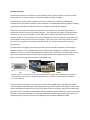
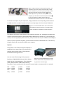
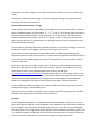
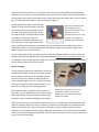
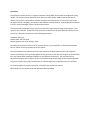
Ancillary Equipment Operation Procedures
This document describes how to use all the ancillary equipment in the Center for Cognitive and
Behavioral Brain Imaging at the Ohio State University. We will briefly describe some design ideas, but
mostly focus on how to operate the equipment, and the precautions you need to take.
The ancillary equipment includes those devices used to deliver visual stimulus and auditory stimulus,
collect subject response, record speech, and track eye movement. Figure 1 shows the data flow among
different devices.
The idea is to control all the devices by one of the stimulus computers. The KVM switch is connected to
stimulus computers on the left side of Figure 1, and is used to switch to one of the computers into the
system. The hollow arrows from computers indicate multiple-cable connections, including audio,
microphone, USB, and DVI. All other ancillary devices, except the VGA video path, are connected directly
or indirectly to the KVM. We will discuss each piece of equipment later. Although Figure 1 looks
complicated, the usage of the system is actually simple.
Audio
splitter
Windows XP
Linux
Personal
Amplifier
Speakers for experimenter
Headset
Speech recording interface
Microphones
USB
hub
Keyboard/mouse Eye
tracker
USB-Ethernet
PC
E-prime, Eyelink keys
RTBox
Keypad
VGA
HiFi earphone
Siemens music
KVM
switch
DVI
T14
fOPR
interface
DVI splitter
Projector
Eye
camera
Response
pads
Monitor
VGA splitter
Figure 1. The diagram for signal flow among different devices. The idea of the design is to allow different
stimulus computers to easily control all the devices. If one of the Center provided computers is used, the is
no need to plug or unplug any device. If a personal computer is used to control stimulus, the computer’s
video, USB, and maybe audio and microphone ports need to be connected to the KVM. The signal in the
dashed lines is the analog video signal, which is used only if the personal computer doesn’t have DVI
output. The speaker for experimenter is used to monitor what the subject hears. The monitor shows what
the subject sees. The green boxes indicate the equipment attached to the subject. The orange boxes
indicate the equipment an experimenter needs to operate. Note the arrows in the diagram indicate major
directions of signal flow.
Stimulus computers
The stimulus computer is a computer to control displays and/or sound to subject, and collect subject
button response. It can also be used it to record the subject’s speech if needed.
To be flexible for various research projects, the Center provides two computers, a Windows XP
computer and a Linux Ubuntu computer. Both computers are installed with common software packages,
including Microsoft Office and Matlab. E-prime is installed on the Windows computer.
Some users may choose to use their own computer to run experiments. The advantage is obvious
because you have full control of your own computer --- the experimental program can be fully tested,
you won’t run into any incompatibility issues, and you don’t need to copy behavioral data from the
stimulus computer. For this purpose, we reserve a KVM port for personal computers, which will be the
user’s laptop most of time, but can be any computer. If you use E-prime, don’t worry about its license
key. Once your computer is connected to the KVM switch, you will have access to the license key
automatically.
For video output, we suggest you use DVI if possible. Our two stimulus computers use DVI output to
drive the projector. If your computer doesn’t have a DVI port, but DisplayPort or HDMI, we provide
adaptors to convert it into DVI. Some computers may only have a VGA output. The video quality of VGA
may not be as good as DVI because there is a long cable between the computer and the projector.
Figure 2 shows several common computer video output ports.
DVI
VGA
DisplayPort
HDMI
Figure 2. Common computer video ports. DVI is recommended, although VGA is supported too. DisplayPort
is used by some new computers, and HDMI is the popular port for HDTVs. Both DisplayPort and HDMI can
be converted into DVI.
If you use your own computer, you will need to connect it to the KVM switch. The cables you need to
connect include a video cable (DVI or VGA depending on your video output), a USB cable, a 3.5mm audio
output cable (green connector) if you want to play audio from your computer, and a 3.5mm audio cable
(pink connector) if you want to record speech during experiment. Figure 3 shows the various connectors.
After you connect your computer to the system, the monitor (together with the projector) will be your
secondary display. You may need to set the settings for this display to 1280x1024 at 60Hz.
Figure 3. Cable connectors to the personal computer. You
will need to connect one of the video ports (DVI or VGA)
and the USB cable. If you want to play any sound, you will
also need to connect the green connector ( ) to your
audio output port. If you want to record speech to your
computer, you will need to connect the pink connector ( )
to your microphone port. Note that the audio and
microphone ports have the same size, so you will need to
distinguish them by colors or symbols.
To choose the computer for your experiment, simply press down the corresponding switch button on
the KVM switch for a couple of seconds until you hear a beep. Figure 4 is the 4-channel KVM switch.
Figure 4. Four-channel KVM switch. This is the switch to
select different stimulus computers. It will switch video,
audio, microphone, and USB to one of the computers.
The USB port will connect several devices to the computer you switch into, including the keyboard and
mouse to control the computer, response pad, RTBox, USB hub on the monitor (e.g., you can plug your
memory stick to copy data), E-prime license key, and eye tracker host PC (via a USB to Ethernet adaptor).
In short, if you use your own computer, you will need to connect the needed cables to it. Then the only
thing you need to do is to switch the KVM to your computer.
Projector
The projector is one of the most important pieces of
equipment for our setup. Figure 5 is a picture of the
projector and its remote control. The projector is
located behind the magnet room.
Here are some default settings for the projector.
Figure 5. The Christie DS+6K-M DLP projector
Resolution: 1280x1024; Refresh rate: 60 Hz; Display
and its remote control. A special lens is used
height: 22.0 cm; Viewing distance: ~70 cm; Gamma: 1
to generate the smaller image.
(linear); Max luminance: 33401 (before reducing
intensity); CIE color coordinates at half-maximum intensity (need to re-measure after Y is reduced):
Red:
Green:
Blue:
Gray:
x=0.666
x=0.338
x=0.145
x=0.310
y=0.334
y=0.642
y=0.044
y=0.329
Y= 3001
Y=13291
Y= 1016
Y=17415
These result in 59 pixels per degree. If you need to control exact stimulus size, you can simply use this
number.
The projector is calibrated at this setting. You must not change the setting of the projector without
discussing it with the Center personnel.
Response collection and scanner TR trigger
We use the fiber optical response pads (fORP) in the magnet. There are two response pads, each with 2
buttons. The default buttons are four numbers, "1", "2", "3", and "4". The TR trigger from the scanner is
also connected to the fORP interface, and represented as "5". In other words, if a window, such as
NotePad or Matlab window, is open, you will see "1" through "4" when a subject presses one of the
buttons, and you will see a "5" whenever there is a TR trigger from the scanner. These buttons can be
set to other key names if needed.
The typical way to synchronize the stimulus and MRI acquisition is to use the first TR trigger to start your
stimulus presentation. The TR trigger is issued once at the beginning of each TR.
Another option to collect responses is to use the RTBox driver. The RTBox (response time box) is
designed to measure accurate response time. In our setup, it receives signals from the fOPR interface, so
you can use the same response pads for the subject. The only difference is the command to read the
response in your code.
The first time you connect your own computer to the KVM switch, you may see that your computer
detects some USB devices, including a USB-to-serial converter, which is for the RTBox. To use it, you
need to install its driver. If your computer doesn’t have its driver, you can go to
http://www.ftdichip.com/Drivers/VCP.htm and download the driver for your computer system. If you
use Matlab, you are strongly recommended to use the RTBox. Besides the response time accuracy, you
won’t have those numbers popped into your program window. Also, KbCheck in Psychtoolbox for
Matlab can’t reliably detect the key press from the fORP, due to fORP’s hardware limitations.
In E-prime and other software packages, you can treat the RTBox as a serial response box. Each event,
including the TR trigger, is represented by a byte.
In any case, once you connect the USB cable to your computer, you will have access to both the fORP
and RTBox. You simply choose the one that is convenient for you.
Eye glasses
For those subjects whose glasses are not MRI safe, lenses will be provided. Our sphere lens (for both
positive and negative) range from 0.12 to 20 diopters, with reasonable steps. We also have cylinder lens
(0.12 to 6 diopters for both positive and negative) and prisms (0.5 to 10), which can be used together
with sphere lenses. You are suggested to ask the subject in advance whether he/she wears glasses, and
if yes, whether the glasses are MRI safe, and if not, find out their prescription. Just make sure we have
the lens for him/her. Always put the lens back to their original slots after you use them.
Figure 6 shows the whole set of lenses and the frame for the lenses.
Figure 6. Left picture shows the whole lens set, and right picture shows the frame with three lenses
installed for left eye. In the lens box, the negative diopters are red, and positive are black. The 4 middle
columns, 2 red and 2 black, are cylinder lenses, and 4 side columns are sphere lenses. In the center, there
are two rows of white lenses. The right row is prisms. The left row is labeled as accessories, which are for
special test purpose.
Auditory stimulus
The audio signal from your stimulus computer can be delivered to the subject either via the Siemens
auditory system or our HiFi system. If you use your personal computer, you will need to connect the
audio output to the green audio connector (Figure 3).
We have two auditory delivery systems. For most users, the audio signal from the computer may be
simple feedback, such as beep or a simple sound, indicating correct or incorrect responses. For this
purpose, the Siemens built-in auditory system should be good enough. If the head coil is large enough,
you can ask subject to wear the Siemens headset along with earplugs. Then both your instruction voice
and the computer audio signal will go to the headset. Even if the head coil is too small such that subject
can't wear the headset, the audio will be delivered into the magnet bore, and subject can hear it if the
volume is loud enough. To make sure the audio from
Figure 7. Siemens intercom.
the computer is delivered to subject, the Music LED on
The button with a music
the Siemens intercom (Figure 7) should be on. You can
symbol is used to turn on and
off the audio signal from
press the Music button to turn it on or off.
The Siemens audio system is easy to use. But if you
need high quality auditory signal, you will use our HiFi
system. To use this system, you need to turn on the
amplifier (Figure 8) in the equipment rack under the
counter. The two volume knobs on the amplifier can
be used to adjust the volume, but you won’t have to
do that most of the time. You normally adjust
volume on your computer. Please keep in mind to
computer. The LED on it
indicates on/off status.
Figure 8. HiFi Audio amplifier. You normally need
to only turn it on and off.
always start from low volume on your computer. This is because the sound signal is delivered to the
subject's ear canals directly. You can gradually increase the volume till subject can hear clearly without
any discomfort. Since the Siemens audio system will also play sound into magnet bore, you may want to
turn it off using the Music button on Siemen intercom (Figure 7).
The earplugs for HiFi audio are special plugs
Figure 9. HiFi earphones and
(Figure 9). You will ask the subject to screw it
their earplugs. Red one is
to the plastic tube of the earphone for each
right channel and blue one for
ear. Then squeeze the plug and put into the
left channel (you can
ear canal to allow it to expand. Please inform
remember this by two R’s: red
your subject to be gentle to the wire
for right). The earplugs are
screwed on the plastic tubes.
connected to the earphone. When taking it
out from the ear canal, hold the red or blue
piece, instead of pulling the wire. Since this ear plug is more expensive than regular ones, you are
requested to keep it in a small plastic bag, label the bag with subject name, and use it again if the
subject is going to run multiple sessions.
To ensure high quality audio, you will also need to apply the software equalizer to your wav files. The
software works only for Windows and can be downloaded at http://www.sens.com/downloads/. You
are advised to collect all your wav files, and do the conversion once. It is every easy to use the software.
You can check its manual (link) if you need it.
Speech recording
If you record speech during an experiment, you will use
the MRI safe microphone. We use two straps to attach
the microphone stand to the coil, and adjust the flexboom to place the microphone to subject mouth as
close as possible (Figure 10). This is very critical for get
better speech signal. We have two microphones, and
they can be used to do noise cancelling purpose.
Please note that, the microphone is connected to an
optic fiber, and you should never pull the fiber too hard.
When adjusting the microphone position, always hold
the boom to bend, instead of holding the microphone.
Figure 10. The speech recording microphone,
the flex-boom and stand to mount. The
microphone should be as close to the
subject’s mouth as possible, but without
touching the subject.
When you switch to one of the stimulus computers you use, the recording will also be switched to the
stimulus computer. Most of the time, the stimulus computer can record speech as a background task
while presenting stimulus. If this is not the case, you have to use your laptop or another stimulus
computer to record speech, and you need an additional connection for this to work. We have a Matlab
code to perform the recording in background, and you need to insert only one line into your code where
you will like to start recording.
Eye tracker
The Eyelink Eye tracker host PC is a special computer running DOS, which makes the acquisition timing
reliable. This may be hard to operate for most users, but users seldom need to operate the host PC
directly. The host PC is connected to stimulus computers via Ethernet port. To control the eye tracker
through a stimulus computer, you could use the software from SR-research, Psychtoolbox within Matlab,
E-prime, or other packages if there is Ethernet port control.
The two stimulus computers are set so they can control the eye track PC through your program. If you
use your own computer, for the first time, you have to manually set the extra Ethernet connection (not
your built-in Ethernet connection) to the following parameters:
IP address: 100.1.1.2
Subnet mask: 255.255.255.0
Default gateway and other settings: blank.
Normally the eye tracker system is off. If you want to use it, you simply turn on the switch behind the
host PC, which will turn on all devices for the system.
The infrared emitter eye camera and its lens are located at the lower portion of the rear projection
screen. Occasionally, you may need to adjust the camera focus in case that eye image is not focused well.
This may happen when participant head size is very different from others. You just need a minor
adjustment using the focus knob on the lens. You need to bring the eye image to the stimulus computer
so you can view the eye image. The best focus is achieved when the cornea reflection is the sharpest.
For command detail to control eye tracker, consult the eye tracker user manual.
More details for eye camera setup and calibration will be available.