1
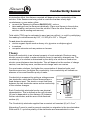
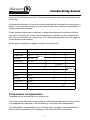
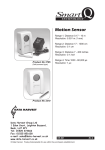
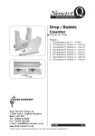
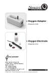
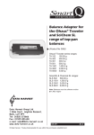
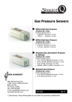
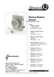
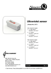
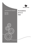
Smart
Q
TECHNOLOGY
Conductivity
Sensor
The Conductivity Adapter
(Product No. 3135)
Range 1: 0 to 100 μS
Range 2: 0 to 1000 μS
Range 3: 0 to 10 mS (10,000 μS)
Range 4: 0 to 100 mS (100,000 μS)
The Conductivity
Electrode
(Product No. 3136)
Built -in automatic temperature
compensation.
Cell constant tolerance: ±20%
DATA HARVEST
Data Harvest Group Ltd
1 Eden Court, Leighton Buzzard,
Beds, LU7 4FY
Tel: 01525 373666
Fax: 01525 851638
e-mail: [email protected]
www.data-harvest.co.uk
DS 031
© Data Harvest. Freely photocopiable for use within the purchasers establishment.
No 5
Smart
Q
Conductivity Sensor
TECHNOLOGY
Contents
Introduction ...................................................................................................
Connecting ...................................................................................................
To set the range ......................................................................................
Taking measurements ..................................................................................
User calibration.............................................................................................
Practical information .....................................................................................
Theory ..........................................................................................................
Temperature compensation ..........................................................................
Cleaning, storage and maintenance of the Electrode...................................
Investigations................................................................................................
Does the concentration of a solution affect
movement across a membrane? ............................................................
Warranty .......................................................................................................
1
1
2
2
3
4
6
7
7
8
8
10
Introduction
The Smart Q Conductivity adapter enables a Conductivity electrode to be
connected to an EASYSENSE unit. The EASYSENSE unit will detect when the
Conductivity adapter is connected and which of the ranges it is set to.
The Smart Q Conductivity Sensor is used to measure the conductivity of a solution.
The Conductivity electrode is a simple epoxy-bodied carbon (graphite plate) type
selected for its durability in field use. It is ideal for measuring salinity and changes in
conductivity of a water sample. It can be used by chemists for investigating the
difference between ionic and molecular compounds in an aqueous solution.
Although it will not identify the specific ions that are present, it can be used to
determine the total concentration of ions in a sample.
The SI unit of conductance is Siemens per cm (S/cm). This was formerly known as
a mhos (equal to S/cm) or CF units (mS/cm x 10). The siemen is a large unit, so the
value for aqueous samples is commonly expressed in microsiemens (μS).
Connecting
Connect the sensor lead
from the EASYSENSE to
the shaped socket on the
Conductivity adapter
Connect the Conductivity
electrode to the other end
1
Smart
Q
Conductivity Sensor
TECHNOLOGY
•
•
•
•
•
Hold the Conductivity adapter housing with the Smart Q label showing on the
top.
Connect one end of the sensor cable (supplied with the EASYSENSE unit)
into the input socket on the EASYSENSE unit with the locating arrow facing
upwards.
Connect the other end of the sensor cable into the shaped socket on the
Conductivity adapter with the locating arrow on the cable facing upwards.
Connect the Conductivity electrode (with the locating arrow facing upward) into
the socket on the other end of the Conductivity adapter.
The EASYSENSE unit will detect that the Conductivity Sensor is connected and
display values using the currently selected range. If the range is not suitable for
your investigation, set to the correct range.
To set the range
All Smart Q sensors are supplied calibrated. The stored calibrations for this Sensor
are the 100 μS, 1000 μS, 10 mS and 100 mS ranges.
It is also possible for the user to adjust the calibration constants of the electrode for
more accurate readings – these are stored as ‘User’ ranges, i.e.100 μS User, 1000
μS User, 10 mS User and 100 mS User. See user calibration on page 3.
•
•
•
•
•
Connect the Conductivity Sensor to the EASYSENSE
unit.
Start the EASYSENSE program and select one of the
logging modes from the Home page e.g. EasyLog.
Select Sensor Config from the Settings menu.
Select the Conductivity Sensor from the list (it will be
listed using its current range) and click on the
Change Range button.
The current range will be highlighted. Select the
required range and click on OK.
Close Sensor Config. Click on New and then Finish
for the change in range to be detected by the logging
mode.
The range setting will be retained until changed by the user. With some
EASYSENSE units it is possible to change the range from the unit. Please refer to
the EASYSENSE unit’s user manual.
2
Smart
Q
Conductivity Sensor
TECHNOLOGY
Taking measurements
Inbuilt Temperature
Sensor
Graphite
Plate
Cell
Chamber
The Conductivity Electrode
•
•
•
•
Graphite
Plate
If possible, soak the tip of the Conductivity electrode in deionised water for
about 30 minutes to make sure the electrodes are clean. If not, rinse the tip
thoroughly with deionised water before use.
Wipe the outer part of the electrode body with a clean paper towel. Shake
vigorously to remove any droplets from the cell chamber. If possible, wash the
tip in a sample of the solution to be tested.
Place the Conductivity electrode in the sample to be tested. The sample must
be at least 3 cm deep to ensure the cell chamber is fully submerged.
Stir the solution gently to get rid of any air bubbles that could be trapped in the
cell chamber. Wait for 10 seconds to allow the readings to stabilize.
Note: If you are taking readings in a solution that has a temperature below 10ºC or above 35ºC, allow
more time for the readings to stabilize.
•
•
If the value is above, below or near to the maximum or minimum value in the
current range, alter the selected range of the Sensor.
Clean thoroughly when testing is complete to avoid any contamination when the
electrode is next used.
User calibration
All Smart Q Sensors are supplied calibrated. The stored calibrations for this Sensor
are utilized when any of the default ranges are selected i.e.100 μS, 1000 μS,
10 mS, 100 mS. These ranges are suitable for most investigations.
Conductivity is measured by putting a voltage across two electrodes (graphite
plates), which have a fixed area and are a fixed distance apart. The electric current
that flows between the two graphite plates varies as the conductivity of the solution
changes. Each Conductivity electrode has its own physical characteristics (a small
difference in the exact area and distance apart from one graphite plate to another).
This is defined as the cell constant (K). See Theory on page 6. If you are
performing an experiment that requires a very accurate calibration, it is possible for
the user to adjust the calibration to the K-value of the electrode (the User
calibration).
3
Smart
Q
Conductivity Sensor
TECHNOLOGY
The accuracy of the User calibration will depend upon the condition of the electrode
and the accuracy of the calibration solution. It is best to perform and save the
calibration with the electrode while it is new and uncontaminated.
Only one conductivity calibration solution is required to calculate the K value for an
electrode. Select a calibration solution that is closest to the estimated value of your
sample solutions. An accurate calibration solution is essential. It is best to purchase
prepared solutions from a supplier such as Scientific and Chemical Supplies Ltd,
(web site: www.scichem.co.uk). Although recipes are available for preparing
calibration solutions, it is extremely difficult to make an accurate solution.
•
•
•
•
•
•
•
Ensure the Conductivity electrode is uncontaminated. Soak the tip of the
electrode in deionised water for about 30 minutes. Wipe the outer body of the
electrode with a clean dry paper towel. Shake vigorously to remove any
droplets from the cell chamber and allow to air dry.
Connect the Conductivity Sensor to the EASYSENSE unit.
Start the EASYSENSE program and select one of the logging modes from the
Home page e.g. EasyLog. Select Sensor Config from the Settings menu.
Select the Conductivity Sensor from the list (it will be listed using its current
range) and click on Change Range. Select a User range suitable for the value
of the calibration solution e.g. for an 84 μS solution select the 100 μS User
range, OK.
Select Calibrate Sensor.
Wash the tip of the Conductivity electrode in a sample of the Conductivity
calibration solution. Place the electrode in the calibration solution, which must
be at least 3 cm deep. Stir the solution gently and wait for 10 seconds to allow
the readings to stabilize.
Type the value of the calibration solution (in μS
or mS) into the second calibration point box
and click on Next.
Note: 1,000 μS = 1 mS.
•
•
•
The K value for the electrode will be calculated by
the program e.g. K Value = 0.99876. This value
can either be applied to the other User ranges (click
on Yes) or just to the selected range (click on No).
A message to say ‘The User range has been
reprogrammed ….’ will be displayed. Disconnect
the Conductivity Sensor from the EASYSENSE unit and then reconnect for the
calibration to be applied.
Change the range of the Sensor to the correct User range.
The User calibration values will be stored in the Sensor and will be retained until
reconfigured by the user.
4
Smart
Q
Conductivity Sensor
TECHNOLOGY
Practical information
The Conductivity electrode needs to be kept clean and free of deposits and other
types of build-up. This epoxy cell type of electrode has ‘easy to clean’ graphite
plates which are corrosion safe and less easily contaminated.
If used in solutions with a high ion concentration, it is possible for the graphite
plates to become contaminated. Soak the electrode cell portion in water with a mild
detergent for 15 minutes. Then soak in a dilute acid solution such as 0.1 mol dm-3
hydrochloric acid or 0.5 mol dm-3 acetic acid for another 15 minutes. Rinse well with
distilled water.
The most common reason for inaccurate measurements is cross contamination
of samples. Take care not to transfer droplets of one sample to another. Wash the
electrode with distilled water between test solutions and shake vigorously to remove
droplets. Ideally air-dry and then wash the cell in a sample of the solution to be
measured.
Be sure that samples are capped to prevent evaporation. It is best to fill sample
bottles to the brim to prevent a gas such as carbon dioxide dissolving in the water
sample.
Do not use in a situation that could result in damage to the graphite plates in the cell
chamber. Do not attempt to blot or wipe the inside of the cell.
The automatic temperature compensation for this electrode operates over the range
10ºC to 35ºC, but it can be placed in solutions within a temperature range of 0 to
80ºC.
There may be a decrease in accuracy when used in solutions that have a
conductance of above 20 mS (20,000 μS). Measurements above 50 mS will be
approximate. If samples need to be diluted, use fresh deionised water (to reduce
inaccuracy caused by variation in the conductivity of the deionised water).
The Conductivity electrode not only measures conductivity between the graphite
plates but also, to a lesser extent, in a field to the sides the electrode. In a narrow
vessel, the walls may interfere with this field. If the electrode is held too close to
the top of the liquid level or other objects (e.g. the bottom of a beaker) an incorrect
reading may result.
Interference may occur between electrochemical sensors (pH, Oxygen, and
Conductivity) if they are placed in the same solution at the same time and
connected to the same EASYSENSE unit. This is because these sensors make an
electrical connection to the solution; therefore an electrical path exists between the
sensors through the solution. Maximise the distance between the Sensors to
5
Smart
Q
Conductivity Sensor
TECHNOLOGY
minimise the effect, the distance required will depend on the conductivity of the
solution. If the Sensors are being used in a solution that has a fairly high
conductance e.g. sea water, either:
• connect the Sensors to different EASYSENSE units or
• take readings from the Sensors individually. (Place one Sensor in the solution,
take a reading, and remove from the solution. Place the other Sensor in the
solution, take a reading and remove).
Total solids (TDS) can be estimated in ppm (part per million) i.e. mg/L by multiplying
the reading in microSiemens by 0.67, i.e. 200 μS x 0.67 = 134 ppm.
Do not place the electrode in:
• viscous organic liquids such as heavy oils, glycerine or ethylene glycol
• in acetone
• non-polar solvents such as pentane or hexane.
Theory
Electrical conductivity is an inherent property of most materials. Electrons carry
electric current in metal; in water electrical current is carried by charged ions. The
conductivity of a solution is determined by the ability of a solution to conduct an
electric current between two electrodes. This will depend on the number of charge
carriers, how fast they move, and how much charge each one carries.
For most water solutions, the higher the concentration of dissolved salts, and
therefore more ions, the higher the conductivity. Low conductivity will indicate an
absence of ions and therefore purity of water.
Conductivity is measured by putting a voltage across
two electrodes, which have a fixed area and are a
fixed distance apart. The electric current that flows
between the two electrodes varies as the conductivity
of the solution changes.
Each Conductivity electrode has its own physical
characteristics. This is defined as the cell constant
(K) and is dependent on the distance (D) between
the two electrodes, and the area of the electrode
surface (A).
Distance
between
electrodes
(D)
Electrode
surface
(A)
K=
D
A
Graphite
electrodes
The Conductivity electrode supplied has a nominal cell constant (K) of 1.0 cm-1.
Alternating Current is used to prevent complete ion migration to the two electrodes.
With each A.C. cycle the polarity of the electrodes are reversed which in turn
6
Smart
Q
Conductivity Sensor
TECHNOLOGY
reverses the direction of ion flow. This will prevent electrolysis and polarisation from
occurring.
Although the presence of ions due to dissolved salts will increase the conductivity of
water, it is not specific and can only be used to determine solution concentration if a
single known salt is present.
Some species ionise more completely in water than others do, and their solutions
are more conductive as a result. Each acid, base or salt has its own characteristic
curve for concentration vs. conductivity. The relationship persists until very large ion
concentrations are reached.
Some typical conductivity ranges of hydrous solutions are:
Sample
Conductivity microScm-1 (μS/cm)
Ultra pure water
0.055
Distilled water
0.5 - 5
Rain water
20 - 100
Drinking water
50 - 200
Tap water
100 - 1500
River water
250 - 800
Brackish water
1000 - 8000
KCI 0.01M
1,410
MgSO4
5,810
KCI 0.1M
12,900
Ocean water
53,000
H2S04
82,600
KCI 1.0M
112,000
Range 1
Range 2
Range 3
Range 4
Temperature compensation
Temperature has a large effect on conductivity.
The Conductivity electrode incorporates an in-built temperature sensor that is used
to compensate for changes in the conductivity of solutions with temperature.
The temperature compensation is to counteract real changes in the conductivity of
solution with temperature, not variations in the electrode with temperature.
7
Smart
Q
Conductivity Sensor
TECHNOLOGY
For example: a 0.01 mol dm-3 KCl solution has a conductivity of 1413 μS at 25ºC. Its
conductivity changes from 1020 μS at 10ºC to 1552 μS at 30ºC. The Smart Q
Conductivity Sensor will read a value of approximately 1413 μS at any temperature
in the 10 to 35ºC range.
This allows the conductivity of sample solutions to be compared without bringing
them all too exactly the same temperature.
Cleaning, storage and maintenance of the electrode
Depending on the sample application, the electrode may require cleaning
periodically to ensure accurate measurements.
•
•
•
•
Water-soluble contamination can be removed by soaking in distilled water.
Petroleum-based contamination can be removed by soaking in warm water and
a mild detergent for 15 minutes.
Ethanol may be used to clean the electrode as long as the wash time is limited
to a maximum of 5 minutes.
Lime or hydroxide coating can be removed by soaking in a dilute acid solution
such as 0.1 mol dm-3 hydrochloric acid or 0.5 mol dm-3 acetic acid for 15
minutes.
After cleaning, rinse well with distilled water, shake vigorously and leave to air-dry.
Store the electrode dry.
Investigations
•
•
•
•
•
•
•
•
•
•
Electrolytes and non-electrolytes
Conductivity of saltwater
Equivalence point
Conducting solutions
Water quality - using the 0 - 1000 μS range to test samples of water.
Milk quality
Speed of diffusion
Strength of weak acids & bases
Finding the concentration of unknown samples
Diffusion through membranes
8
Smart
Q
Conductivity Sensor
TECHNOLOGY
Does the concentration of a solution affect movement across a
membrane?
Note: Pre-soak the
Visking tubing for
24 hours before
starting this
experiment (unless
the tubing has
already been used).
Conductivity
electrode
500ml
beaker
Piece of
Visking tubing
approx
10 cm long
Deionised
water
Magnetic stirrer
Test solutions:
No 1 = 1% w/v Salt solution
No 2 = 2% w/v Salt solution
No 3 = 3% w/v Salt solution
No 4 = 4% w/v Salt solution
1. Attach the Conductivity Sensor to the EASYSENSE unit.
2. Open the EASYSENSE program and select Graph from the Home page. From
the Logging Wizard select a 10 minute recording time with an interval of
1 second.
3. Place the Conductivity electrode in the deionised water. Turn the magnetic
stirrer on to give a slow agitation.
4. Select Test Mode from the Tools menu to determine the initial conductivity of
the deionised water. Use this information to select a suitable range from Sensor
Config (in Settings).
Note: The 0 - 1,000 μS range would be suitable for water that has a conductivity of less than 50 μS.
If the value is between 50 - 400 μS consider still using this range but reduce the percentage of salt in
the test solutions e.g. 0.5%, 1%, 1.5%, 2%. If the value is higher than 400 μS, use the 0 to 10 mS
range and increase the percentage of salt in the test solutions.
5. Fill the Visking tubing with the 1% salt solution. Seal the open end. Rinse the
Visking under running water. Place the tubing in the beaker of water and click on
the Start icon to begin logging.
6. When the logging has finished discard the contaminated water and rinse the
electrode with fresh deionised water.
7. Select Overlay.
8. Refill the beaker with the same amount of fresh deionised water and repeat the
experiment using the other test solutions.
9
Smart
Q
Conductivity Sensor
TECHNOLOGY
For this graph we used analytical water with a conductivity of less than 10 μS with
1%, 2% and 3% test solutions using the 0 - 1,000 μS range. Gradient was then
used to calculate the rate of change at mid-point.
Warranty
All Data Harvest Sensors are warranted to be free from defects in materials and
workmanship for a period of 12 months from the date of purchase provided they
have been used in accordance with any instructions, under normal laboratory
conditions. This warranty does not apply if the Sensor has been damaged by
accident or misuse.
In the event of a fault developing within the 12-month period, the Sensor must be
returned to Data Harvest for repair or replacement at no expense to the user other
than postal charges.
Note: Data Harvest products are designed for educational use and are not intended for use in industrial,
medical or commercial applications.
WEEE (Waste Electrical and Electronic Equipment) Legislation
Data Harvest Group Ltd are fully compliant with WEEE legislation and are pleased to provide
a disposal service for any of our products when their life expires. Simply return them to us
clearly identified as ‘life expired’ and we will dispose of them for you.
10