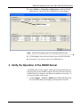
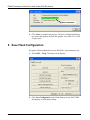
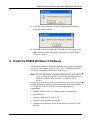
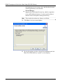
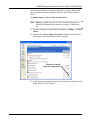
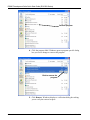
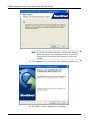
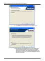
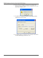
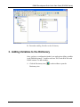
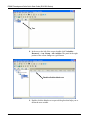
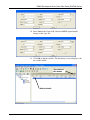
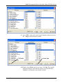
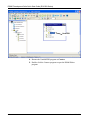
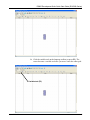
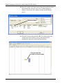
1
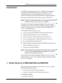
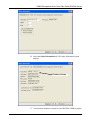
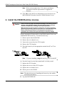
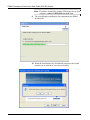
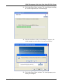
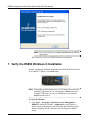
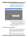
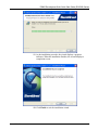
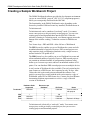
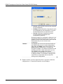
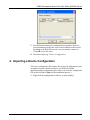
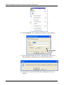
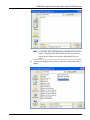
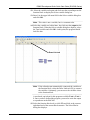
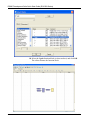
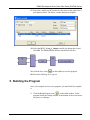
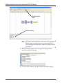
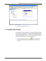
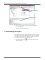
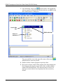
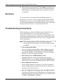
Form A6274 Part Number D301598X012 March 2009 DS800 Development Suite Quick Start Guide for the ROC800-Series Remote Automation Solutions DS800 Development Suite Quick Start Guide (ROC800-Series) Revision Tracking Sheet March 2009 This manual may be revised periodically to incorporate new or updated information. The revision date of each page appears at the bottom of the page opposite the page number. A change in revision date to any page also changes the date of the manual that appears on the front cover. Listed below is the revision date of each page (if applicable): Page Initial issue Revision Mar-09 © 2009 Remote Automation Solutions, division of Emerson Process Management. All rights reserved. NOTICE Remote Automation Solutions (“RAS”), division of Emerson Process Management shall not be liable for technical or editorial errors in this manual or omissions from this manual. RAS MAKES NO WARRANTIES, EXPRESSED OR IMPLIED, INCLUDING THE IMPLIED WARRANTIES OF MERCHANTABILITY AND FITNESS FOR A PARTICULAR PURPOSE WITH RESPECT TO THIS MANUAL AND, IN NO EVENT SHALL RAS BE LIABLE FOR ANY INCIDENTAL, PUNITIVE, SPECIAL OR CONSEQUENTIAL DAMAGES INCLUDING, BUT NOT LIMITED TO, LOSS OF PRODUCTION, LOSS OF PROFITS, LOSS OF REVENUE OR USE AND COSTS INCURRED INCLUDING WITHOUT LIMITATION FOR CAPITAL, FUEL AND POWER, AND CLAIMS OF THIRD PARTIES. Bristol, Inc., Bristol Canada, BBI SA de CV and Emerson Process Management Ltd., Remote Automation Solutions division (UK) are wholly owned subsidiaries of Emerson Electric Co. doing business as Remote Automation Solutions (“RAS”), a division of Emerson Process Management. ROC, FloBoss, ROCLINK, Bristol, Bristol Babcock, ControlWave, TeleFlow and Helicoid are trademarks of RAS. AMS, PlantWeb and the PlantWeb logo are marks of Emerson Electric Co. The Emerson logo is a trademark and service mark of the Emerson Electric Co. All other trademarks are property of their respective owners. The contents of this publication are presented for informational purposes only. While every effort has been made to ensure informational accuracy, they are not to be construed as warranties or guarantees, express or implied, regarding the products or services described herein or their use or applicability. RAS reserves the right to modify or improve the designs or specifications of such products at any time without notice. All sales are governed by RAS’ terms and conditions which are available upon request. RAS does not assume responsibility for the selection, use or maintenance of any product. Responsibility for proper selection, use and maintenance of any RAS product remains solely with the purchaser and end-user. ii Issued Mar-09 DS800 Development Suite Quick Start Guide (ROC800-Series) Introduction The DS800 Development Suite software (“DS800”) is an integrated development environment that allows you to build IEC 61131-3 compliant programs. You install DS800 on your PC and use the software to develop programs and download those programs (using an Ethernet connection) to the ROC800-Series device (“ROC800”). Note: For further technical information, refer to the specification sheet DS800 Development Suite Software (4.1:DS800). This Quick Start Guide provides both a high-level overview and the detailed steps you need to install and configure the DS800 software on your PC. It also provides a very simple example of building an IEC 61131-3 compliant program. The installation process requires you to: 1. Verify versions of ROCLINK 800 and the ROC800 firmware. 2. Install the DS800 Runtime License in the ROC800. 3. Verify the operation of the DS800 kernel in the ROC800. 4. Create a configuration file (which the DS800 software uses). 5. Save the ROC800 Flash configuration. 6. Install the DS800 Workbench software (DS800 Development Suite and LicenseManager) on your PC. 7. Verify the successful installation. Note: To understand all the steps and system requirements, we suggest that you read through this entire guide before you begin the installation and configuration process. After you have successfully installed the software, review Creating a Sample Workbench Project for a detailed example of building a simple IEC 61131-3 program. 1. Verify Versions of ROCLINK 800 and ROC800 When using DS800 Development Suite software version 2.1 with the ROC800, the software requires: Version 1.80 (or greater) of ROCLINK 800. Version 2.10 (or greater) of ROC800-Series firmware. To verify the versions: 1. Start ROCLINK 800. Issued Mar-09 1 DS800 Development Suite Quick Start Guide (ROC800-Series) 2. Click Help on the ROCLINK 800 tool bar and click About ROCLINK 800 from the drop-down menu. The About ROCLINK 800 screen displays. Software Version 3. Verify that the version of ROCLINK 800 is 1.80 or greater. Note: If the version is not at least 1.80, contact your Remote Automation Solutions representative to upgrade ROCLINK 800. 4. Click OK. The ROC800 graphic displays. 5. Click ROC on the ROCLINK 800 toolbar and click Information on the drop-down menu. The Device Information screen displays. 2 Issued Mar-09 DS800 Development Suite Quick Start Guide (ROC800-Series) 6. Select the Other Information tab. The Other Information screen displays. Firmware Version 7. Verify that the firmware version for your ROC800 is 2.10 or greater. Issued Mar-09 3 DS800 Development Suite Quick Start Guide (ROC800-Series) Note: If the version is not at least 2.10, contact your Remote Automation Solutions representative to upgrade the firmware. 8. Click OK to close the Device Information screen, but do not exit ROCLINK 800. Proceed to Install the DS800 Runtime License. 2. Install the DS800 Runtime License Caution Failure to exercise proper electrostatic discharge precautions (such as wearing a grounded wrist strap) may reset the processor or damage electronic components, resulting in interrupted operations. When working on units located in a hazardous area (where explosive gases may be present), make sure the area is in a non-hazardous state before performing procedures. Performing these procedures in a hazardous area could result in personal injury or property damage. Remote Automation Solutions delivers the DS800 runtime license on a standard ROC800 license key. To install a license key: 1. Remove power from the ROC800. 2. Remove the wire channel cover. 3. Unscrew the screws from the CPU faceplate. 4. Remove the CPU faceplate. 5. Place the license key in the appropriate terminal slot (P2 or P3) in the CPU. Incorrect Correct Note: If you are installing a single license key, place it in slot P2. 6. Press the license key into the terminal until it is firmly seated. 7. Replace the CPU faceplate. 8. Replace the screws on the CPU faceplate. 9. Replace the wire channel cover. 10. Restore power to the ROC80. Note: The physical process of installing the license key also enables any licenses on that key. 11. Log onto ROCLINK 800. 4 Issued Mar-09 DS800 Development Suite Quick Start Guide (ROC800-Series) 12. Select Utilities > License Key Administrator on the ROCLINK 800 menu bar. The License Key Administrator screen displays. DS800 License Note: The ROC800 displays the active DS800 Runtime license. 13. Click Cancel to close this screen but do not exit ROCLINK 800. 14. Proceed to Verify the Operation of the DS800 Kernel. 3. Verify the Operation of the DS800 Kernel The DS800 kernel is the “engine” which runs inside the ROC800 and interprets and executes DS800 programs. Because the kernel is part of the ROC800-Series firmware, no software installation is necessary. To verify the operation of the kernel: 1. Click Configure > Control > DS800 on the ROCLINK 800 menu bar. The DS800 dialog box displays, showing the General tab: Issued Mar-09 5 DS800 Development Suite Quick Start Guide (ROC800-Series) Mode is On Task is Enabled Kernel is Running 2. Verify that the Mode option is On. This enables the DS800 kernel. 3. Verify that the Running checkbox in each of the three task areas is checked. This confirms that the runtime kernel is executing. Note: Installing the license key should correctly set these fields. If the checkboxes are not selected, perform a warm start, and re-check the License Key Administrator to make sure the DS800 license is installed. 4. Click OK. Proceed to Create Configuration File. 4. Create Configuration File Creating a configuration (.800) file preserves the I/O configuration you have defined on your ROC800. The DS800 Workbench software uses this configuration file (and its defined point types) to correctly map information you define in the Workbench back to your ROC800. To create a configuration file: 1. Click File > Save Configuration on the ROCLINK 800 menu bar. A Save As dialog screen displays. 6 Issued Mar-09 DS800 Development Suite Quick Start Guide (ROC800-Series) 2. Complete the File name field with a meaningful file name (here, Test09-30-2008). Click Save. ROCLINK 800 displays a dialog box that shows the progress of the save. Note: By default, ROCLINK 800 places all configuration files in the /ROCLINK800 folder on your PC. A change in the Status message indicates when the process finishes. Issued Mar-09 7 DS800 Development Suite Quick Start Guide (ROC800-Series) Save completed 3. Click Close to complete the process. The Save Configuration dialog box closes and displays the ROC800 graphic. Proceed to Save Flash Configuration. 5. Save Flash Configuration Saving the Flash configuration in your ROC800 is a precautionary step. 1. Select ROC > Flags. The Flags screen displays. 2. Click Save Configuration in the Flash Memory frame. ROCLINK 800 displays a confirmation dialog: 8 Issued Mar-09 DS800 Development Suite Quick Start Guide (ROC800-Series) 3. Click Yes. ROCLINK 800 saves the configuration and displays a dialog box when it finishes. 4. Click OK to close this dialog box. The Flags screen displays. Click OK to display the ROC800 graphic. Proceed to Install the DS800 Workbench Software. 6. Install the DS800 Workbench Software The DS800 Workbench software provides the development environment you use to create DS800 “projects” (IEC 61131-3 compliant programs) which you consequently download to the ROC800. Note: For more information on creating DS800 projects, refer either to Create a Sample Workbench Program in this document or to the DS800 Development Suite Software User Manual (Form A6126). Remote Automation Solutions delivers the DS800 Workbench software on a CD-ROM. Your PC must have the following minimum requirements: Issued Mar-09 Pentium-class processor (233 MHz or greater recommended). CD-ROM drive. Windows 2000 (Service Pack 2), XP. Ethernet (recommended) or serial port. Administrative privileges for the PC on which the software is to be installed. 9 DS800 Development Suite Quick Start Guide (ROC800-Series) Caution A Sentinel USB license key provides access to all the DS800 Workbench features. Do not insert the Sentinel USB license key in any USB port on your PC until directed to do so. Using the key before the Workbench is completely installed may cause unpredictable results. To install the software: 1. Place the CD-ROM into your PC’s CD drive. The Product Installer wizard starts automatically. Note: If you have Autorun enabled on your computer, the Product Installer wizard starts automatically. If you have disabled Autorun, use this procedure to start the wizard: a. b. c. 2. 10 Click Start > Run. The Run dialog box displays. Click Browse, navigate to the folder on the CD-ROM containing the Workbench software, and select the Setup.exe file in that folder. The Run dialog box displays. Click OK. The Product Installer wizard screen displays. Click Next. A software license agreement displays. Issued Mar-09 DS800 Development Suite Quick Start Guide (ROC800-Series) 3. Read the entire DS800 software license agreement. If you agree to the terms of the license, select I accept the terms of the license agreement and click Next. A Select Features screen displays. 4. Use this screen to select the two DS800 features you must install: Issued Mar-09 Development Suite 800 Also known as the “Workbench,” this is the development 11 DS800 Development Suite Quick Start Guide (ROC800-Series) environment you use to create, view, and download custom control applications to the ROC800. LicenseManager Supports the USB Sentinel license key which is required to access all Workbench features. You also use this utility to transfer licenses and update existing license keys. Note: The wizard selects these two features as defaults. 12 5. Click Next. A review screen displays. 6. Review the options you have selected for installation and click Next. The DS800 initial (or “splash”) screen displays. Issued Mar-09 DS800 Development Suite Quick Start Guide (ROC800-Series) Note: Once you begin the DS800 installation process, you cannot stop it until it completes. Issued Mar-09 7. Click Install. The wizard prompts you to select the location for the installed software. 8. Click Next to accept the default location or click Browse to select another location. 13 DS800 Development Suite Quick Start Guide (ROC800-Series) Note: If you have inserted the Sentinel USB license key in your computer, remove it BEFORE you click Next. 9. The wizard begins installing the first component (the DS800 Workbench). 10. When the installation of the Workbench completes, the wizard prompts you to include an icon on your desktop. 14 Issued Mar-09 DS800 Development Suite Quick Start Guide (ROC800-Series) 11. Click either Yes or No to continue. The wizard begins installing the second component (the LicenseManager). 12. When the installation of the LicenseManager completes, the wizard prompts you to include an icon on your desktop. 13. Click either Yes or No to continue. The wizard prompts you to restart your computer. Issued Mar-09 15 DS800 Development Suite Quick Start Guide (ROC800-Series) Note: Until you restart your computer, do not start the DS800 application. 14. Proceed to Verify the DS800 Workbench Installation. 7. Verify the DS800 Workbench Installation Remote Automation Solutions distributes the DS800 Workbench license on a Sentinel® USB key with a blue label: Note: During this verification process, you are instructed to insert this Sentinel USB license key in your computer. Do not insert the Sentinel USB license key into a USB port on your computer until directed to do so. To start Workbench: 1. Click Start .> Programs > Emerson Process Management > DS800 2.1 (select the DS800 2.1 application, not the folder). A splash screen (indicating the version number and build date for the software) displays briefly, and then closes to display the DS800 screen. 16 Issued Mar-09 DS800 Development Suite Quick Start Guide (ROC800-Series) Red “banner” at bottom of screen indicates Technician (read-only) mode The red banner at the bottom of the DS800 screen indicates that the software successfully installed but was unable to find the license key. 2. Exit the application (select File > Exit on the DS800 menu bar). 3. Insert the Sentinel USB license key into a USB port on your computer. Windows automatically recognizes the USB device and displays a recognition message in the System Tray. Issued Mar-09 17 DS800 Development Suite Quick Start Guide (ROC800-Series) Note: If Windows does not automatically recognize the USB device, proceed to the Troubleshooting section of this document. 4. Click Start > Programs > Emerson Process Management > DS800 2.1 (again, select the application and not the folder). The splash screen displays, followed by the DS800 screen. No “banner” at bottom of screen indicates DS800 has recognized the license key Note: This version of the DS800 screen does not have a red banner across the bottom of the screen. This means that DS800 detected the license key and changed the Workbench functionality accordingly. If the DS800 still has a red banner, proceed to Troubleshooting the Installation in this document. 5. You can begin to develop DS800 projects. Refer to Creating a Sample Workbench Project in this guide. Troubleshooting the Installation The DS800 Development Suite software and the USB Sentinel license key use Sentinel Protection from SafeNet® Incorporated. Other software vendors today use the same technology, so if Windows does not recognize an attached USB license key, it’s possible that conflicting versions of the SafeNet Sentinel software are installed on your computer. To resolve this conflict, you must uninstall all versions of the Sentinel driver from your computer and install the latest version. The updated 18 Issued Mar-09 DS800 Development Suite Quick Start Guide (ROC800-Series) driver allows Windows to recognize the USB license key and does not adversely affect any other programs which use the SafeNet Sentinel driver. To uninstall prior versions of the Sentinel driver: Note: Before you update any drivers, close all applications (such as DS800 Development Suite) which may require a USB license key. 1. Open the Windows Control Panel (click Start > Settings > Control Panel). 2. Double-click Add or Remove Programs. Windows builds a list of all programs currently installed on your computer. Click here to scroll down the program list 3. Scroll down the program list until you find software programs which begin with the word “Sentinel.” Issued Mar-09 19 DS800 Development Suite Quick Start Guide (ROC800-Series) Sentinel program 4. Click the program label. Windows opens a program-specific dialog box you use to change or remove this program. Click to remove the program 5. Click Remove. Windows displays a verification dialog box asking you to verify the removal request. 20 Issued Mar-09 DS800 Development Suite Quick Start Guide (ROC800-Series) 6. Click Yes to continue. Windows displays a number of dialog boxes as it removes the program. If necessary, the last dialog box reminds you to restart your computer. Note: If you have several programs to remove, remove all programs before you restart your computer. 7. Repeat steps 3-6 for any other Sentinel drivers. When you have uninstalled all previous versions of Sentinel drivers, you can install the most current Sentinel driver. To install the most current version of the Sentinel driver: 1. Place the CD-ROM you used to install the DS800 software in your computer’s CD drive. 2. Click Start > Run. The Run dialog box displays. 3. Click Browse. Remote Automation Solutions placed the 7.5.0 Sentinel driver in the \Sentinel folder on the CD-ROM. Select the Sentinel System Driver Installer 7.5.0.exe file. The Run dialog box displays the selected file. 4. Click OK. The InstallShield wizard displays. Issued Mar-09 21 DS800 Development Suite Quick Start Guide (ROC800-Series) Note: If you have not removed all prior versions of the Sentinel Protection Installer, the wizard detects those versions and displays this screen to ensure the upgrade of all previous versions. 5. Click Upgrade. The wizard displays the installation splash screen. 6. Click Next. A license agreement screen displays. 22 Issued Mar-09 DS800 Development Suite Quick Start Guide (ROC800-Series) 7. Select I accept the terms in the license agreement and click Next. The wizard displays a screen for the type of setup. 8. Select Complete and click Next. The wizard displays a screen used to start the actual installation. Issued Mar-09 23 DS800 Development Suite Quick Start Guide (ROC800-Series) 9. Click Install. The wizard displays a security settings screen. 10. The DS800 does not include the ability to access Sentinel license keys from a remote machine. If you are aware of any installed software on your computer which requires this functionality, click Yes. Otherwise, click No. The wizard begins installing the software based on your selections. 24 Issued Mar-09 DS800 Development Suite Quick Start Guide (ROC800-Series) 11. As the installation proceeds, the wizard displays a progress indicator. When the installation finishes, the wizard displays a completion screen. 12. Click Finish to exit the installation wizard. Issued Mar-09 25 DS800 Development Suite Quick Start Guide (ROC800-Series) Creating a Sample Workbench Project The DS800 Workbench software provides the development environment you use to create DS800 “projects” (IEC 61131-3 compliant programs) which you consequently download to the ROC800. The functionality in the DS800 Workbench varies depending on the license key installed. With no license key installed, Workbench runs in Technician mode. Technician mode can be considered “read-only” mode. You cannot create a new project or edit previously created projects. You can view existing projects and download them into the ROC800. When the software is running in Technician mode, a red banner appears across the bottom of the window reading “Technician version for DS800 users only.” Two license keys—PR2 and PRD—allow full use of Workbench. The PR2 license key enables you to use Workbench to create and edit an unlimited number of projects. However, PR2-created projects can only contain a single configuration (hardware unit), a single resource, and are limited to 128 points of I/O. The PRD license key also enables you to use Workbench to create and edit an unlimited number of projects. However, PRD-created projects can contain an unlimited number of configurations (hardware units), define up to 4 resources per unit, and have an unlimited number of I/O points. You can distribute PRD-created projects across multiple devices. A trial version of Workbench is also available. The trial version has the same features as a PRD license, but it operates for only 30 days. After 30 days the trial expires and you must uninstall the software. Any projects you may have created with the trial version require a copy of Workbench with a PR2 or PRD license key. Contact your local Remote Automation Solutions representative to receive a copy of the trial version of Workbench. Hardware Units Supported Resources per Hardware I/O Points Unlimited 4 Unlimited PR2 1 1 128 PRD Unlimited 4 Unlimited Trial Unlimited 4 Unlimited Technician Notes Cannot create or edit projects Expires in 30 days Technician mode is basically a “read-only” mode. You cannot create new projects or edit previously created projects, but you can view existing projects and download projects. 26 Issued Mar-09 DS800 Development Suite Quick Start Guide (ROC800-Series) Getting Started with DS800 The DS800 workbench is designed to help you build process control applications. You can distribute these applications across several platforms or enable the applications to communicate with each other through networks. A DS800 project shows the distribution and links between each PLC loop, which the DS800 kernel (or “virtual machine”) executes on each platform. Using the function block diagram language, this section details the steps required to build a sample project (creating an incrementing counter in a soft point parameter) and familiarizes you with the views, buttons, and vocabulary of DS800. The following steps are involved: 1. Creating a New Project 2. Importing a Device Configuration 3. Adding Variables to the Dictionary 4. Creating a Program to the Resource 5. Compiling the Program 6. Compiling the Project 7. Downloading the Project 8. Debugging the Project 9. Verifying the Program in ROCLINK 800 1. Creating a New Project To create a new DS800 project: 1. Click the DS800 2.1 icon on your desktop. The DS800 workspace screen displays. Note: If you did not create a desktop icon for this application, you can also click Start > Programs > Emerson Process Management > DS800 2.1. 2. Click the New Project icon ( ) on the DS800 workspace toolbar. A New project dialog box displays. Issued Mar-09 27 DS800 Development Suite Quick Start Guide (ROC800-Series) Complete Name field Default template Note: By default, DS800 places project files in the folder C:\Program Files \ Emerson Process Management\ Projects\ DS800 2.1. If you want your project files in another location, click Browse to select that location. 3. Enter ROC800_SampleProject1 in the Name field. DS800 completes the Template field with the default value SingleROC800E (a single ROC800 using Ethernet connections). Note: You can click d in the Template field to display other templates. 4. Click OK. The DS800 Resource view screen displays. DS800 Toolbar Views Toolbar 28 Issued Mar-09 DS800 Development Suite Quick Start Guide (ROC800-Series) Use the icons on the DS800 toolbar and the Views toolbar to work with the project data. Small descriptive tags (“tool tips”) appear as you move the cursor over each toolbar icon. 5. Double-click the hardware architecture icon ( ) on the Views toolbar to display the Hardware Architecture view. Resource Network Driver This screen shows your project in relationship to existing hardware. Resource A resource is composed of programs and corresponds to a PLC loop. You compile a resource and then download its code to configuration, where the DS800 kernel (“virtual machine”) executes it. Configuration A hardware platform, linked to other hardware platforms by a serial network. Use DS800’s Hardware Architecture view to display configurations. Target You attach a configuration to a specific target. A target contains definitions about the hardware platform and the virtual machine running on it. Double-click the configuration’s title bar to display a Configuration Properties screen, which has three tabs: Issued Mar-09 29 DS800 Development Suite Quick Start Guide (ROC800-Series) General, which provides a title and any comments for the configuration. Hardware, which indicates the target device (such as the ROC809) for this configuration. This is the tab that displays when you open this screen. Security, which sets a password security to prevent unauthorized changes to the configuration’s properties. Specifying a target for a configuration affects the list of functions and function blocks that you can call in your programs, the list of I/O devices that you can use, and the networks that you can connect to your configuration. Network The ROC800 can communicate with the Workbench (the DS800 utility you use to create configurations) using either the ISARSI (serial) network driver or the ETCP (Ethernet) network driver. You select this through the template. The Hardware Architecture view provides a reminder of what network driver you are using. ETCP is the standard driver Remote Automation Solutions provides to communicate over an Ethernet network. The Workbench debugger also uses ETCP to communicate with the resources running on the configurations. 6. Double-click the vertical (connection) line to open the connection configuration. A Connection Properties screen displays. 30 Issued Mar-09 DS800 Development Suite Quick Start Guide (ROC800-Series) 7. For an Ethernet connection, configuration is automatic. However, you can manually modify the value of the IP address on this screen according to the ROC800-series device you intend to connect to. Click OK to save the value. 8. Proceed to Importing a Device Configuration. 2. Importing a Device Configuration The device configuration file contains device-specific information (such as number of points, number of meters, and TLPs) the DS800 application needs to appropriate place data. (You created a configuration file for the ROC800 in Step 4 of the installation process.) 1. Right-click the configuration’s title bar. A menu displays. Issued Mar-09 31 DS800 Development Suite Quick Start Guide (ROC800-Series) 2. Select Properties. The Configuration Properties screen displays. Configuration selector 3. Click the right-most browse button. A message box cautions you that importing a configuration may reload the entire project. 4. Click Yes. The Select ROCLINK 800 Configuration File screen displays. 32 Issued Mar-09 DS800 Development Suite Quick Start Guide (ROC800-Series) Note: As a default, ROCLINK 800 stores configuration files in the folder C:\Program Files\ROCLINK800. You may need to browse to this folder to locate the configuration file you want. 5. A dialog box displays that you use to select the configuration file to import. Issued Mar-09 33 DS800 Development Suite Quick Start Guide (ROC800-Series) 6. Select a file and click Open. A message box may display if the Workbench changes the IP address for the configuration to the value stored in the configuration file. 7. Click OK. The Configuration Properties screen displays with the configuration you have selected. 8. Click OK to apply the configuration file to the project. Once the file is loaded, DS800 displays the Resource view. 34 Issued Mar-09 DS800 Development Suite Quick Start Guide (ROC800-Series) 9. Proceed to Adding Variables to the Dictionary. 3. Adding Variables to the Dictionary Once you have a configuration loaded, you can begin to define variables in the DS800 dictionary. Variables associate TLPs in the ROC800 with DS800 content. To add variables: 1. Click the Dictionary icon ( ) on the toolbar to open the Dictionary view. Issued Mar-09 35 DS800 Development Suite Quick Start Guide (ROC800-Series) Tree 2. In the tree to the left of the screen, double-click Variables > Resource1 > Any Group > All variables. The panel in the right portion of the screen changes to a grid format. Double-click the blank row 3. Double-click the blank row to open a dialog box that helps you to define the new variable. 36 Issued Mar-09 DS800 Development Suite Quick Start Guide (ROC800-Series) 4. Enter Total in the Name field, and select DINT (signed double integer) in the Type file. 5. Click OK to add the variable. The Dictionary screen redisplays with the variable added. “Spreadsheet” view button Added variable Issued Mar-09 37 DS800 Development Suite Quick Start Guide (ROC800-Series) Note: Click the button in the upper right corner of the variable view to display the variable table in an editable spreadsheet format. 6. To define a second variable that is connected to a parameter in the ROC800, double-click the highlighted blank row to open the dialog box. 7. Click the TLP browse button on the dialog box. TLP browse button A TLP Browser screen displays. 8. Select 98 – Soft Point Parameters in the Point Type column. The program completes the Logical Number and Parameter columns. 38 Issued Mar-09 DS800 Development Suite Quick Start Guide (ROC800-Series) 9. Leave SFP 1 as the value in the Logical Number column and select 21 – Long 1 in the Parameter column. TLP value Access type 10. Finally, select Write as the access type. Click OK. The variable dialog box displays. Note that the values in several fields have changed to correspond to your defined variable. Issued Mar-09 39 DS800 Development Suite Quick Start Guide (ROC800-Series) 11. Click OK to add the variable to the dictionary. 12. Click the Save icon ( ) to save your changes to the dictionary. 13. Click the Link Architecture view icon ( ) to display the project’s link architecture. 14. Proceed to Adding a Program to the Resource. 40 Issued Mar-09 DS800 Development Suite Quick Start Guide (ROC800-Series) 4. Adding a Program to the Resource Using the Link Architecture view, you can see how the components of your DS800 project fit together. The next step is to give the ROC800 resource functionality by adding a program: 1. Right-click Programs in the Resource1 box. A menu displays. 2. Move the cursor over the Add Program option to display a menu of programming languages. 3. Select FBD: Function Block Diagram. The Link Architecture view displays, showing an unnamed FBD. Issued Mar-09 41 DS800 Development Suite Quick Start Guide (ROC800-Series) New FBD 4. Rename the UntitledFBD program as Counter. 5. Double-click the Counter program to open the DS800 Editor program. 42 Issued Mar-09 DS800 Development Suite Quick Start Guide (ROC800-Series) Function block tool (F3) 6. Click the function block tool on the language toolbar (or press F3). The cursor becomes a function block tool once you move it into the editor grid. 7. Move the cursor in the middle of the editor screen and click. A Select Blocks screen displays. Issued Mar-09 43 DS800 Development Suite Quick Start Guide (ROC800-Series) 8. In the right-hand panel, select the second block option (Addition of two or more integer or…) and click OK. The editor changes the shape of the generic function block to an addition function block. Note the two inputs on the left side of the block and one output (which provides the sum) on the right side of the block. 44 Issued Mar-09 DS800 Development Suite Quick Start Guide (ROC800-Series) 9. Click the variable tool on the language toolbar (or press F2). The cursor becomes a variable tool once you move it into the editor grid. Variable tool (F2) Issued Mar-09 45 DS800 Development Suite Quick Start Guide (ROC800-Series) 10. Move the variable tool close to one of the inputs on the left side of the function block and click. The Select Variable dialog box displays, which shows the variables currently defined for this project. Defined variables 11. Select the Total variable and click OK. The editor renames the variable and, if the variable is close to the function block, automatically links the variable and function block. Renames and links variable to function block 46 Issued Mar-09 DS800 Development Suite Quick Start Guide (ROC800-Series) 12. Select the variable tool again and click near the second input on the function block to display the Select variable dialog box. 13. Enter 1 in the upper left-most field in the Select variable dialog box and click OK. Note: This value is not a variable, but is a constant value. 14. Select the variable tool a third time, but click near the output on the function block. When the Select variable dialog box displays, select the Total variable and click OK. At this point, the program should look like this: Draw Link tool Note: If the editor has not automatically connected the variables to the function block, select the Draw Link tool (F4) to connect the variables. Alternately, you can move the variables closer to the function block. A text-based equivalent for this program would be Total = Total + 1. Once you have defined the program, you need to write the output to a parameter in the ROC800. 15. Select the function block tool (or click F3) and click at the extreme right-hand end of the current block structure. The Select Blocks dialog box displays. Issued Mar-09 47 DS800 Development Suite Quick Start Guide (ROC800-Series) 16. Select the 1 gain function block (as shown above) and click OK. The editor renames the function block. 48 Issued Mar-09 DS800 Development Suite Quick Start Guide (ROC800-Series) 17. Select the variable tool (F2) and move the cursor to the right of the 1 gain function block. The Select variable dialog box displays. 18. Select the SPF_1_Long_1_Output variable (as shown above) and click OK. The finished block structure should look like this: 19. Click the Save icon ( ) on the toolbar to save the program. 20. Proceed to Building the Program. 5. Building the Program Once you complete and save your program, you must build (or compile) it. 1. Click the Build Program icon ( ) on the editor toolbar. As the program builds, the Output window at the bottom of the screen notes any errors or warnings. Issued Mar-09 49 DS800 Development Suite Quick Start Guide (ROC800-Series) Build Program icon Output window Note: The Output window shows the result of the code generation. During testing, it can also show any execution messages. You can change the height of the window to display more or fewer lines. 2. When the build completes, the message in the Output window should resemble the following: 3. Close the editor window. The main workbench window displays. 50 Issued Mar-09 DS800 Development Suite Quick Start Guide (ROC800-Series) 4. Proceed to Compiling the Project. 6. Compiling the Project As noted before, a project may have one or more programs. Our simple project has only one program, but if your project has multiple programs, you need to successful compile—or “build”—each program (when the Output window displays 0 error(s), 0 warning(s)). Only then should you attempt to compile the project. To compile the project: 1. Click the Build Project/Library icon ( ) on the DS800 toolbar. The Output window indicates whether any errors or warnings occurred: Issued Mar-09 51 DS800 Development Suite Quick Start Guide (ROC800-Series) Build Project/Library icon Output window 2. For a successful compile, the Output window should display 0 error(s), 0 warning(s). 3. Proceed to Downloading the Project. 7. Downloading the Project Once you have successfully compiled the project, you can download it to the ROC800 for execution there. Ensure that your PC is connected via an Ethernet connection to the target ROC800 (the same ROC800 from which you imported your configuration file). 1. Click the download icon ( ) on the toolbar. The Download dialog box displays. 52 Issued Mar-09 DS800 Development Suite Quick Start Guide (ROC800-Series) 2. Click Select All to choose the resource you want to download. (For this sample project, we defined only one resource.) You can deselect any resources you want to omit them from this download. 3. Click Download to start the download process. When the download completes, DS800 displays the following message in the Output portion of the Workbench screen. Note: If the message Error occurred during downloading to configuration! Connection to the Configuration Manager failed displays, refer to Troubleshooting Connections at the end of this manual. 4. Proceed to Debugging the Project. 8. Debugging the Project Debug mode enables you test resources while you are online. The debug routine establishes a connection with the hardware and displays the current value of variables while the code executes. This “live view” helps you to detect and remove errors. Note: You must have successfully downloaded a project to use debug mode. To start a debugging session: Issued Mar-09 53 DS800 Development Suite Quick Start Guide (ROC800-Series) 1. Click the Debug Target icon ( ) on the toolbar. The Workbench software connects to the ROC800 and includes the word RUN in the title of the Resource 1 dialog box. Icon in title bar RUN in title bar Colors in resource The green and blue icon in the upper left corner of the screen ( indicates that no errors are present. ) 2. Double-click the Counter program to open the editor. 3. Review the real-time results of the program. The editor displays the block diagram showing the current value of the variables and the output of the function blocks. The value increases at a rate of 10 times per second, which is how frequently the code executes by default. 54 Issued Mar-09 DS800 Development Suite Quick Start Guide (ROC800-Series) Incrementing value 4. Click the Stop Debug Target icon ( ) on the toolbar to stop the real-time display and exit Debug mode. Close the editor. The DS800 screen displays. 5. Proceed to Verifying the Program in ROCLINK 800. 9. Verifying the Program in ROCLINK 800 The final step in the process of developing a program is to access ROCLINK 800 software and verify that the program is correctly incrementing the soft points you have targeted. 1. Disconnect from DS800. 2. Connect to the ROC800 using ROCLINK 800. 3. Select Configure > I/O > Soft Points from the ROCLINK 800 menu bar. The Soft Point screen displays. Incrementing value Issued Mar-09 55 DS800 Development Suite Quick Start Guide (ROC800-Series) 4. Note the value in the Integer field. Click Update several times over 5-10 seconds, and watch the value increase. This indicates that the DS800 program is incrementing that value 10 times per second, as you intended. Summary To meet the needs of your organization, the DS800 programs you develop will—of course—be more complex than this simple example. But the processes you use to develop those programs are the same. If you need further information on the DS800 software, refer to the DS800 Development Suite Software User Manual (Form A6126). Troubleshooting Connections While attempting to download a DS800 project to the ROC800, you may see the message Error occurred during downloading to configuration! Connection to the Configuration Manager failed. This means that the Workbench cannot communicate with the DS800 kernel inside the ROC800. Following are some tips to help you diagnose and resolve this problem. Note: These solutions assume you have an Ethernet connection between the ROC800 and the PC on which the DS800 software is installed. Can you ping the ROC800? Open up a command window (Start > Run > cmd.exe) and enter the command ping nnn.nnn.nnn.nnn (where nnn.nnn.nnn.nnn represents the IP address of your ROC800). If you get no response, then there is a network connection problem. Does the ROC have a DS800 Runtime License? Using ROCLINK 800, check if the ROC800 in question has a DS800 Runtime License. (Utilities > License Key Administrator). If the license is not present, then DS800 projects cannot download. Is the configuration connected? Check, using the Hardware Architecture view of the Workbench, that the Configuration box representing the ROC is connected via a vertical line to the ETCP network. Does the configuration in the project have the right IP address? Check that the IP address in the DS800 Hardware Architecture view, connection properties, is the same IP address you see in ROCLINK 800 (ROC > Information > Internet). 56 Issued Mar-09 DS800 Development Suite Quick Start Guide (ROC800-Series) Are you connecting to the correct device? Unplug the Ethernet cable from the ROC800 and try to ping the ROC. If you still get a response, then you do not have the correct IP address. Is the DS800 kernel inside the ROC running? Go into the ROCLINK 800 DS800 configuration (Configure > Control > DS800) and ensure that the DS800 "switch" is turned on. Press Update several times to make sure. Are the three associated tasks "Running"? (See 3. Verify Operation of the DS800 Kernel.) Have you accidentally created a Library Project? Does a CD and Book icon display in the lower right corner of the Resource view of the Workbench? If so, you've accidentally created a library, which is not downloadable to a ROC800. You'll need to create a new project with the template SingleROC800E. Issued Mar-09 57 DS800 Development Suite Quick Start Guide (ROC800-Series) 58 Issued Mar-09