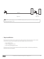
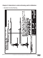
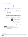
1
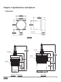
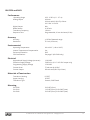
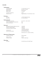
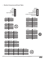
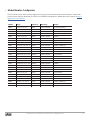
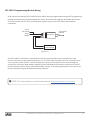
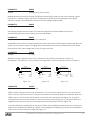
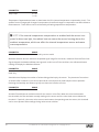
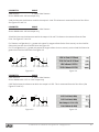
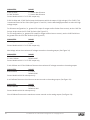
IRU Series Ultrasonic Sensors User Manual IRU-2000’s, IRU-3430’s, IRU-5000’s, IRU-6420’s, & IRU-9420’s APG R Doc #9002662 Rev C, 04/15 Table of Contents Introduction................................................................................................................. iii Warranty and Warranty Restrictions..................................................................... iv Chapter 1: Specifications and Options..................................................................... 1 Dimensions.....................................................................................................................................1-2 Specifications.................................................................................................................................3-7 Electrical Connectors and Pinout Tables.................................................................................... 8 Model Number Configurator........................................................................................................... 9 Wiring Diagrams........................................................................................................................10-12 Chapter 2: Installation and Removal Procedures and Notes............................. 13 Tools Needed.................................................................................................................................... 13 Installation Notes......................................................................................................................13-14 Mounting Instructions.................................................................................................................. 14 Electrical Installation.....................................................................................................................15 Software Installation.......................................................................................................................15 Removal Instructions.....................................................................................................................15 Chapter 3: Set Up and Operation............................................................................. 16 User Interface.............................................................................................................................16-18 IRU Sensor Parameters........................................................................................................... 19-24 Relay and NPN Trip Output Configuration......................................................................... 25-26 Sensor Readings and Communication Status.................................................................... 26-28 Control Buttons......................................................................................................................... 28-29 Saving and Loading Parameter Files.......................................................................................... 29 Chapter 4: Maintenance............................................................................................30 General Care.....................................................................................................................................30 Troubleshooting..............................................................................................................................30 Calibration...................................................................................................................................30-31 Repair and Returns......................................................................................................................... 31 Chapter 5: Hazardous Location Drawing and Certification...............................32 Hazardous Location Drawing....................................................................................................... 32 CSA Certificate of Compliance............................................................................................... 33-35 ii Tel: 1/888/525-7300 • Fax: 1/435/753-7490 • www.apgsensors.com • [email protected] Introduction Thank you for purchasing an IRU ultrasonic sensor from APG. We appreciate your business! Please take a few minutes to familiarize yourself with your IRU and this manual. The IRU series is APG’s line of general purpose ultrasonic sensors. With a choice of operating ranges from just a few inches to as far as 50 feet, the IRU product line is designed to fit a wide range of industrial automation applications. Sensor adjustments, such as sensitivity and filtering options, are made by interfacing the sensor to a PC using an RST module and APG’s free Windows based programming software. IRU sensors incorporate internal temperature compensation for increased accuracy under varying environmental conditions. The sensors are housed in PC/PET or UV resistant ABS to seal out moisture and resist a wide range of chemicals. Reading your label Every APG instrument comes with a label that includes the instrument’s model number, part number, serial number, and a wiring pinout table. Please ensure that the part number and pinout table on your label match your order. The following electrical ratings and approvals are also listed on the label. Please refer to the Certificate of Compliance and Declaration of Conformity at the back of this manual for further details. Electrical ratings Input: 12 to 28 Volts DC, 80mA max; Outputs: 4-20mA, NPN Class I Division 2; Groups C, D T6 Class I, Zone 2, Group IIB AEx nA IIB T6: Ta: -30°C to 60°C; IP65 Ex nA IIB T6: Ta: -30°C to 60°C; IP65 IRU models: IRU-2423, IRU-2425, IRU-3433, IRU-3435, IRU-5413, IRU-5415, IRU-5423, IRU-5425. Models listed are rated for Pollution Degree 2, Installation Category II. Input: 12 to 28 Volts DC, 80 mA max; Outputs: 4-20mA, solid state relay, NPN Listed for General Purpose Ta: -30°C to 60°C; IRU models: IRU-2002, IRU-2003, IRU-2005, IRU-2423, IRU-2425, IRU-33433, IRU-3435, IRU-5413, IRU-5415, IRU-5423, IRU-5425, IRU-5429, IRU-6429, IRU-9423, IRU-9425, IRU-9429 Models listed are rated for Pollution Degree 2, Installation Category II. IMPORTANT: Your IRU must be listed above and installed as shown on drawing 9003066 to meet listed approvals. Faulty installation will invalidate all safety approvals and ratings. Tel: 1/888/525-7300 • Fax: 1/435/753-7490 • www.apgsensors.com • [email protected] iii Warranty and Warranty Restrictions APG warrants its products to be free from defects of material and workmanship and will, without charge, replace or repair any equipment found defective upon inspection at its factory, provided the equipment has been returned, transportation prepaid, within 24 months from date of shipment from factory. THE FOREGOING WARRANTY IS IN LIEU OF AND EXCLUDES ALL OTHER WARRANTIES NOT EXPRESSLY SET FORTH HEREIN, WHETHER EXPRESSED OR IMPLIED BY OPERATION OF LAW OR OTHERWISE INCLUDING BUT NOT LIMITED TO ANY IMPLIED WARRANTIES OF MERCHANTABILITY OR FITNESS FOR A PARTICULAR PURPOSE. No representation or warranty, express or implied, made by any sales representative, distributor, or other agent or representative of APG which is not specifically set forth herein shall be binding upon APG. APG shall not be liable for any incidental or consequential damages, losses or expenses directly or indirectly arising from the sale, handling, improper application or use of the goods or from any other cause relating thereto and APG’s liability hereunder, in any case, is expressly limited to the repair or replacement (at APG’s option) of goods. Warranty is specifically at the factory. Any on site service will be provided at the sole expense of the Purchaser at standard field service rates. All associated equipment must be protected by properly rated electronic/electrical protection devices. APG shall not be liable for any damage due to improper engineering or installation by the Purchaser or third parties. Proper installation, operation and maintenance of the product becomes the responsibility of the user upon receipt of the product. Returns and allowances must be authorized by APG in advance. APG will assign a Return Material Authorization (RMA) number which must appear on all related papers and the outside of the shipping carton. All returns are subject to the final review by APG. Returns are subject to restocking charges as determined by APG’s “Credit Return Policy”. iv Tel: 1/888/525-7300 • Fax: 1/435/753-7490 • www.apgsensors.com • [email protected] Chapter 1: Specifications and Options • Dimensions 3.25” 82.55mm 3.10” 78.74mm 2.60” 66.04mm 2.50” 63.50mm 3.25” 82.55mm 1.63” 41.40mm Liquid Tight Strain Relief IRU-200x 3/4” ø NPT Threads 7.21” 183.13mm 3/4” ø NPT Threads 7.76” 197.10mm 5.08” 129.03mm 2” ø NPT Threads 3” ø NPT Threads 2.27” 57.66mm 3.05” 77.47mm 5.63” 143.00mm 2.80” 71.12mm 1.47” 37.34mm 1.98” 50.29mm 3.00” 76.20mm IRU-242x & IRU-642x IRU-343x Tel: 1/888/525-7300 • Fax: 1/435/753-7490 • www.apgsensors.com • [email protected] 1 Micro Connector 4.54” 115.32mm 4.00” 101.60mm 3.05” 77.47mm 2” ø NPT Threads 0.64” 16.26mm 2” Sanitary Fitting 2.50” 63.50mm IRU-532x 6.10” 154.94mm 3/4” ø NPT Threads 3.97” 100.84mm 2.73” 63.34mm 1” ø NPT Threads 0.68” 17.27mm IRU-541x 5.74” 145.80mm 3/4” ø NPT Threads 2” ø NPT Threads 3.61” 91.69mm 3.05” 77.47mm IRU-542x & IRU-942x 2 Tel: 1/888/525-7300 • Fax: 1/435/753-7490 • www.apgsensors.com • [email protected] • Specifications IRU-200X and 242X Performance Operating Range Analog Output Digital Output Display Output Beam Pattern Transducer Frequency Response Time 1 - 25 ft. (0.3 - 7.6 m) on liquids and hard, flat surfaces 1 - 10 ft. (0.3 - 3 m) on bulk solids 1 Solid State Relay, Isolated 4-20 mA, 4-20 mA, 4-20 mA with 2 NPN Trip Points RS-485 with 1 NPN Trip Point For interface with APG digital display (IRU-2002, IRU-2003 only) 9° off axis 69 kHz Programmable, 20 ms minimum (50 Hz) Accuracy Accuracy±0.25% of detected range Resolution 0.1 inch (2.54 mm) Environmental Operating Temperature Internal Temperature Compensation Enclosure Protection NEMA rating CSA Certifications -40 to 60°C (-40 to 140°F) Yes IP65 (IRU-242X) 4X (IRU-2000X only) See page iii (IRU-242X only) Electrical Opperational Supply Voltage (at sensor) Programming Supply Voltage Current Draw Current Output 12-28 VDC 15-28 VDC 80 mA max @ 24 VDC (IRU-200X) 75 mA max @ 24 VDC (IRU-242X) 300 mA max (NPN Trip Points) 130 mA max (SSR, 120 VDC or VAC) Materials of Construction Transducer Housing Upper Housing Transducer Type ABS with UV inhibitor (IRU-200X) PVDF (Kynar®) (IRU-242X) PC/PET (IRU-242X) ABS (IRU-200X) Ceramic, PVDF faced (IRU-242X) Mounting IRU-200X IRU-242X Surface Mount with Four Screws 2” Ø NPT (front), 3/4” Ø NPT (rear) Tel: 1/888/525-7300 • Fax: 1/435/753-7490 • www.apgsensors.com • [email protected] 3 IRU-343X Performance Operating Range Analog Output Digital Output Beam Pattern Transducer Frequency Response Time 1.25 - 50 ft. (0.4 - 15.2 m) 4-20 mA 4-20 mA with 2 NPN Trip Points N/A 9° off axis 43 kHz Programmable, 45 ms minimum (22 Hz) Accuracy Accuracy±0.25% of detected range Resolution 0.1 inch (2.54 mm) Environmental Operating Temperature Internal Temperature Compensation Enclosure Protection CSA Certifications -40 to 60°C (-40 to 140°F) Yes IP65 See page iii Electrical Opperational Supply Voltage (at sensor) Programming Supply Voltage Current Draw 12-28 VDC 15-28 VDC 75 mA max @ 24 VDC Materials of Construction Transducer HousingPC/PET Upper HousingPC/PET Transducer Type Ceramic, PVDF faced Mounting 4 IRU-343X 3” Ø NPT (front), 3/4” Ø NPT (rear) Tel: 1/888/525-7300 • Fax: 1/435/753-7490 • www.apgsensors.com • [email protected] IRU-532X and 54XX Performance Operating Range Analog Output Digital Output Beam Pattern Transducer Frequency Response Time 0.33 - 6.58 ft. (0.1 - 2.7 m) 4-20 mA 4-20 mA with 2 NPN Trip Points 0-2.5 VDC / 0-5 VDC N/A 9° off axis 143 kHz Programmable, 20 ms minimum (50 Hz) Accuracy Accuracy±0.25% of detected range Resolution 0.1 inch (2.54 mm) Environmental Operating Temperature Internal Temperature Compensation Enclosure Protection CSA Certifications -40 to 60°C (-40 to 140°F) Yes IP65 See page iii (IRU-54XX only) Electrical Opperational Supply Voltage (at sensor) Excitation Supply Voltage Programming Supply Voltage Current Draw Current Output 12-28 VDC 5 VDC min. (0-2.5 / 0-5 VDC output only) 15-28 VDC 75 mA max @ 24 VDC 300 mA max (NPN Trip Points) Materials of Construction Transducer HousingPC/PET Upper HousingPC/PET Transducer Type Ceramic, PVDF faced Mounting IRU-532X IRU-541X IRU-542X 2” Ø NPT (front) 1” Ø NPT (front), 3/4” Ø NPT (rear) 2” Ø NPT (front), 3/4” Ø NPT (rear) Tel: 1/888/525-7300 • Fax: 1/435/753-7490 • www.apgsensors.com • [email protected] 5 IRU-642X Performance Operating Range Analog Output Digital Output Beam Pattern Transducer Frequency Response Time 1.0 - 30.0 ft. (0.3 - 9.1 m) 0-2.5 VDC / 0-5 VDC RS-232 option 9° off axis 69 kHz Programmable, 67 ms minimum (15 Hz) Accuracy Accuracy±0.25% of detected range Resolution 0.1 inch (2.54 mm) Environmental Operating Temperature Internal Temperature Compensation Enclosure Protection -40 to 60°C (-40 to 140°F) Yes IP65 Electrical Opperational Supply Voltage (at sensor) Excitation Supply Voltage Programming Supply Voltage Current Draw Serial Communications 12-28 VDC 5 VDC min. 15-28 VDC 12-28 VDC (via RS-232) 75 mA max @ 24 VDC RS-232 (IRU-6429S only) 9600 baud, 8 bit, 1 stop bit, No parity Materials of Construction Transducer Housing PVDF (Kynar®) Upper HousingPC/PET Transducer Type Ceramic, PVDF faced Mounting 6 IRU-642X 2” Ø NPT (front), 3/4” Ø NPT (rear) Tel: 1/888/525-7300 • Fax: 1/435/753-7490 • www.apgsensors.com • [email protected] IRU-942X Performance Operating Range 0.5 - 35 ft. (0.2 - 10.7 m) Analog Output 4-20 mA 4-20 mA with 2 NPN Trip Points 0-2.5 VDC / 0-5 VDC Digital Output RS-232 option (with 0-2.5 / 0-5 VDC only) Beam Pattern 9° off axis Transducer Frequency50 kHz Response Time Programmable, 45 ms minimum (22 Hz) Accuracy Accuracy±0.25% of detected range Resolution 0.1 inch (2.54 mm) Environmental Operating Temperature Internal Temperature Compensation NEMA rating -40 to 60°C (-40 to 140°F) Yes 12 Electrical Opperational Supply Voltage (at sensor) Excitation Supply Voltage Programming Supply Voltage Current Draw Serial Communications 12-28 VDC 5 VDC min. (0-2.5 / 0-5 VDC output only) 15-28 VDC 12-28 VDC (via RS-232) 75 mA max @ 24 VDC RS-232 (IRU-9429S only) 9600 baud, 8 bit, 1 stop bit, No parity Materials of Construction Transducer HousingPC/PET Upper HousingPC/PET Transducer TypeElectrostatic Mounting IRU-942X 2” Ø NPT (front), 3/4” Ø NPT (rear) Tel: 1/888/525-7300 • Fax: 1/435/753-7490 • www.apgsensors.com • [email protected] 7 • Electrical Connectors and Pinout Tables IRU-2002 IRU-2003 +24 VDC +24 VDC DC Ground DC Ground Clock Sync Clock Sync Digital Display Output Digital Display Output Relay 4-20mA Circuit Power (+24 VDC) 4-20mA Output Relay 8 3/C Cable IRU-XXX3-C 8/C Cable IRU-XXX9S-C Red +24 VDC Red +24 VDC Black DC Ground Black DC Ground White 4-20 mA Out Orange Excitation White Voltage Out 5-pin MC IRU-XXX3-M Green Analog Ground 1 Brown +24 VDC Brown RS-232 Ground 2 White Not used 1 2 Yellow RS-232 TX 3 Blue DC Ground 4 3 Blue RS-232 RX 4 Black 4-20 mA Out 5 Grey Not used 8-pin MC IRU-XXX9S-M 6/C Cable IRU-2004-C IRU-2005-C 1 White Voltage Out Red +24 VDC +24 VDC 2 Brown +24 VDC Black DC Ground DC Ground 3 Green Analog Ground 4 Yellow RS-232 TX 5 Grey RS-232 Ground 6 Pink RS-232 RX 7 Blue DC Ground 8 Red Excitation 5 Green Clock Sync Clock Sync White NPN trip NPN 2 Blue T (+) or (B) NPN 1 Orange T(-) or (A) 4-20 mA Out 5/C Cable IRU-XXX5-C IRU-XXX9-C Red +24 VDC +24 VDC Black DC Ground DC Ground White NPN 1 Voltage Out Orange 4-20 mA Out Excitation Green NPN 2 Analog Ground 5-pin MC IRU-2004-M IRU-2005-M IRU-XXX5-M IRU-XXX9-M 1 Brown +24 VDC +24 VDC +24 VDC +24 VDC 2 White T (+) or (B) NPN 1 NPN 1 Voltage Out 3 Blue DC Ground DC Ground DC Ground DC Ground 4 Black T(-) or (A) 4-20 mA Out 4-20 mA Out Analog Ground 5 Grey NPN trip NPN 2 NPN 2 Excitation 1 4 2 5 Tel: 1/888/525-7300 • Fax: 1/435/753-7490 • www.apgsensors.com • [email protected] 3 6 1 7 8 5 4 3 2 • Model Number Configurator The IRU sensor series offers a wide range of housing, outputs, and performance specifications. Please refer to each sensor family’s datasheet for a full list of available configurations. Datasheets can be found at http:// apgsensors.com/support. Model Range Frequency Mounting Output 2002 1-25 ft / 0.3-7.6 m 69kHz Surface/Screws (1) Solid-State Relay 2003 1-25 ft / 0.3-7.6 m 69 kHz Surface/Screws Isolated 4-20mA 2004 1-25 ft / 0.3-7.6 m 69 kHz Surface/Screws RS-485, 1 NPN Trip 2005 1-25 ft / 0.3-7.6 m 69 kHz Surface/Screws 4-20mA, 2 NPN Trip 2423 1-25 ft / 0.3-7.6 m 69 kHz 2” NPT Threads 4-20mA 2425 1-25 ft / 0.3-7.6 m 69 kHz 2” NPT Threads 4-20mA, 2 NPN Trip 3433 1.25-50 ft / 0.4-15.2 m 43 kHz 3” NPT Threads 4-20mA 3435 1.25-50 ft / 0.4-15.2 m 43 kHz 3” NPT Threads 4-20mA, 2 NPN Trip 5323 0.33-6.56 ft / 0.1-2.7 m 143 kHz 2” NPT Threads 4-20mA 5325 0.33-6.56 ft / 0.1-2.7 m 143 kHz 2” NPT Threads 4-20mA, 2 NPN Trip 5329 0.33-6.56 ft / 0.1-2.7 m 143 kHz 2” NPT Threads 0-2.5/0-5 VDC 5413 0.33-6.56 ft / 0.1-2.7 m 143 kHz 1” NPT Threads 4-20mA 5415 0.33-6.56 ft / 0.1-2.7 m 143 kHz 1” NPT Threads 4-20mA, 2 NPN Trip 5419 0.33-6.56 ft / 0.1-2.7 m 143 kHz 1” NPT Threads 0-2.5/0-5 VDC 5423 0.33-6.56 ft / 0.1-2.7 m 143 kHz 2” NPT Threads 4-20mA 5425 0.33-6.56 ft / 0.1-2.7 m 143 kHz 2” NPT Threads 4-20mA, 2 NPN Trip 5429 0.33-6.56 ft / 0.1-2.7 m 143 kHz 2” NPT Threads 0-2.5/0-5 VDC 6429 1-30 ft / 0.3-9.1 m 69 kHz 2” NPT Threads 0-2.5/0-5 VDC 6429S 1-30 ft / 0.3-9.1 m 69 kHz 2” NPT Threads 0-2.5/0-5 VDC, RS-232 9423 0.5-35 ft / 0.2-10.7 m 50 kHz 2” NPT Threads 4-20mA 9425 0.5-35 ft / 0.2-10.7 m 50 kHz 2” NPT Threads 4-20mA, 2 NPN Trip 9429 0.5-35 ft / 0.2-10.7 m 50 kHz 2” NPT Threads 0-2.5/0-5 VDC 9429S 0.5-35 ft / 0.2-10.7 m 50 kHz 2” NPT Threads 0-2.5/0-5 VDC, RS-232 Tel: 1/888/525-7300 • Fax: 1/435/753-7490 • www.apgsensors.com • [email protected] 9 • Wiring Diagrams IRU-2003 Isolated 4-20 mA Source Wiring IRU-2003 +24 VDC DC Ground VDC Source +24 VDC DC Ground Clock Sync Digital Display Output 4-20mA Circuit Power (+24 VDC) 4-20mA Output 4-20mA Receiver +24 VDC 4-20mA Input Figure 1.1 - Isolated VDC Source Wiring IRU-2003 +24 VDC DC Ground Clock Sync Digital Display Output 4-20mA Circuit Power (+24 VDC) 4-20mA Output VDC Source +24 VDC DC Ground 4-20mA Receiver Signal Ground 4-20mA Input IRU-2003 +24 VDC DC Ground Clock Sync VDC Source / 4-20mA Receiver +24 VDC DC Ground 4-20mA Input Digital Display Output 4-20mA Circuit Power (+24 VDC) 4-20mA Output Figure 1.2 - Single VDC Source Wiring The IRU-2003 is equipped with an isolated 4-20 mA output. This means that the 4-20 mA circuit can be powered by the 4-20 mA signal receiver or a source independant of the receiver. An isolated source must be wired correctly to prevent potential ground loops that can exist in instances where the IRU and receiver are not sharing the same power source (See Figure 1.1). The 4-20 mA circuit can also be wired as a standard current sourcing 4-20 mA loop simply by powering the circuit from the same power source used by the main IRU sensor circuit (See Figure 1.2). 10 Tel: 1/888/525-7300 • Fax: 1/435/753-7490 • www.apgsensors.com • [email protected] RST-3001/2 Programming Module Wiring All IRU sensors (excluding the IRU-6429S and IRU-9429S) are fully programmable using an RST programming module, which acts as an interface between the sensor and a personal computer. APG offers two versions of the RST module: the RST-3001 (32-bit Windows systems only), and the RST-3002 (64-bit Windows compatible). Sensor DC Ground SENSOR Sensor +24 VDC 24 VDC _ + RST-3001/2 To Computer USB Port 24 VDC Power Supply Figure 1.3 The RST module is connected in series between the sensor and its power source using the two 2-pin Phoenix connectors on the module (See Figure 1.3). 15-28 VDC from the power source is connected to one 2-pin connector, while the VDC + and DC Ground of the sensor is connected to the module through the second 2-pin connector. When power is applied, the red LED between the Phoenix connectors on the RST should illuminate and the sensor should start audibly “ticking”. The operating parameters of the sensor can then be adjusted using the Windows-based utility software. NOTE: The utility software can be downloaded at www.apgsensons.com/support. Tel: 1/888/525-7300 • Fax: 1/435/753-7490 • www.apgsensors.com • [email protected] 11 Excitation Wiring for IRU-XXX9 Sensors VDC Source IRU-XXX9 +24 VDC +24 VDC DC Ground DC Ground (Other connections vary by model) Analog Receiver / Datalogger +5 VDC Excitation (+5 VDC) 0-2.5 / 0-5 VDC Input 0-2.5 / 0-5 VDC Output Analog Ground Analog Ground Figure 1.4 0-2.5 / 0-5 VDC IRU sensors include an +5 VDC Excitation input. (See Figure 1.4) If voltage is not applied at the Excitation input, the sensor will not communicate for programming, nor will it provide the 0-2.5 / 0-5 VDC output. In essence, this allows for a small VDC supply, such as +5 VDC from a datalogger, to “wake” the sensor for output recording, and subsequently put the sensor back to “sleep.” IRU-200X Clock Synchronization Wiring VDC Source +24 VDC DC Ground +24 VDC DC Ground Clock Sync Outputs (vary) IRU-200X +24 VDC DC Ground Clock Sync Outputs (vary) +24 VDC DC Ground Clock Sync Outputs (vary) IRU-200X IRU-200X Figure 1.5 IRU-2002, IRU-2003, IRU-2004-C, and IRU-2005-C sensors are equiped with a clock synchronization to prevent cross-talk between sensors located in close proximity. When the clock sync terminals of two or more sensors are connected (See Figure 1.5), the output signals will synchronize. The sensors must share a common ground in order for the clock synchronization feature to function. 12 Tel: 1/888/525-7300 • Fax: 1/435/753-7490 • www.apgsensors.com • [email protected] Chapter 2: Installation and Removal Procedures and Notes • Tools Needed Tools are necessary only for the screws used to install the surface mount IRU-200X, and to access the terminal strips inside IRU-2002 and IRU-2003 sensors. All other models can be mounted via NPT threads on the sensors. If you are using a stand pipe to mount your IRU, you will probably need tools to install the stand pipe. NOTE: Terminal strips for IRU-2002 and IRU-2003 sensors are internal to the sensor and must be connected before sensors are mounted. IRU-2003 IRU-2002 +24V +24V GND CLK DIG Logan, UT 84321 (888) 525-7300 RLY RLY Sensitivity GND CLK Logan, UT 84321 (888) 525-7300 Sensitivity DIG 4-20 (+) 4-20 (-) Trip Distance Figure 2.1 Figure 2.2 Potentiometers for setting or adjusting Trip Distance (IRU-2002 only) and Sensitivity (IRU-2002 and IRU-2003) are located inside the sensor housing along with terminal strips (See Figures 2.1 and 2.2). Both settings can also be controlled via the I2000SWR software (See Figure 3.3). • Installation Notes • Mount your IRU sensor so that it has a clear, perpendicular sound path to the surface being monitored. Your sensor should be mounted away from tank or vessel walls and inlets. (See Figure 2.3) • The sound path should be free from obstructions and as open as possible for the 9° off axis beam pattern. • If you are using a stand pipe, please see our guide to stand pipes on our website: http://www.apgsensors.com/about-us/blog/how-to-install-a-stand-pipe. Tel: 1/888/525-7300 • Fax: 1/435/753-7490 • www.apgsensors.com • [email protected] 13 Figure 2.3 NOTE: Do not mount the sensor where the beam will intersect objects such as fill streams, pipes, ladder rungs, wall seams, or corrugated tank walls. • Mounting Instructions Mounting your IRU is easy if you follow a few simple steps: • For IRU-200X sensors, use the necessary screws or bolts (not provided by APG) to mount the sensor. For all other IRU models: • Never over-tighten the sensor. • Always screw in your sensor by hand to avoid cross-threading. Thread failure can be a problem if you damage threads by over-tightening them or by crossing threads. IMPORTANT: Do not over tighten! The sensor should be threaded in only hand tight. 14 Tel: 1/888/525-7300 • Fax: 1/435/753-7490 • www.apgsensors.com • [email protected] • Electrical Installation • Check the pinout table on your IRU against your order • Check that your electrical & control system wiring matches the pinout table on your IRU. • For sensors with connectors, make the connection. For instruments with pigtails, run the cable to a junction box in a suitable location to connect to your system. • For IRU-2002 and IRU-2003 sensors, sytem wiring must be connected to internal terminal strups prior to physical installation. (See Figures 2.1 and 2.2) NOTE: Please see wiring diagrams in Chapter 1 for RST Module Programming Wiring and other special wiring configurations. • Software Installation • • • • • Download the RST-3001 or RST-3002 software zipfile from http://apgsensors.com/support. Open the zip file. Choose “Install” from the options at the top of the zip file window. The installation process will prompt you as needed to complete the installation. The software will create I2000SWR.exe which will run from a folder in your start menu titled “APG/ I2000SWR”. IMPORTANT: RST-3001 software will not opperate in a 64-bit Windows environment. If you have a 64-bit Windows system, you must use RST-3002 software. • Removal Instructions • • • • Ensure that power to the sensor is off Disconnect cable to sensor. Remove the sensor and store it in a dry place, at a temperature between -40° F and 180° F. If the sensor was installed in a hazardous location, ensure that the cable will not energize while the sensor is disconnected. DANGER: Do not disconnect equipment installed in hazardous locations unless power has been switched off or area is known to be non-hazardous. Tel: 1/888/525-7300 • Fax: 1/435/753-7490 • www.apgsensors.com • [email protected] 15 Chapter 3: Set Up and Operation • User Interface IRU sensors use one of two methods for user interface: RS-232 serial communications (IRU-6429S and IRU9429S) or I2000SWR, the Windows-based utility software (all other models). RS-232 Serial Communication Sensors with the built-in RS-232 communications will accept one ASCII command (SEND), and return distance and temperature values in ASCII. When the sensor receives the SEND command (all capital letters), the sensor will transmit the distance in feet, followed by a comma, and then the temperature in degrees Celsius, followed by a carriage return and line feed. The distance will be five characters (e.g. 05.25) and the temperature will have a + or - followed by one or two characters (e.g. +22). NOTE: If your sensor is turned off between readings, you must allow time for the sensor to initialize and process readings through filtering parameters before polling for output readings with a SEND command. Depending your filter settings, this can take between 3 and 30 seconds, or longer. IMPORTANT: The sensor will return ASCII characters, not numeric values. 16 Tel: 1/888/525-7300 • Fax: 1/435/753-7490 • www.apgsensors.com • [email protected] Windows-based Utility Software: I2000SWR I2000SWR software user interface is one screen with three primary areas (See Figure 3.1). The primary portion of the screen is two columns of Sensor Parameters. The Sensor Readings and Communication Status area is below the Sensor Parameters, in two uneven columns. Finally, the Control Buttons area is located across the bottom of the screen. Only the fields in the Sensor Parameters are editable by the user. All of the fields in the Sensor Readings and Communication Status area are display only. Figure 3.1 Tel: 1/888/525-7300 • Fax: 1/435/753-7490 • www.apgsensors.com • [email protected] 17 The top and middle Communication Status boxes in the right column show the status of communication between the I2000SWR software and the RST-3001/2, and between the I2000SWR software and the sensor (See Figure 3.2). Figure 3.2 When the I2000SWR software is started it will attempt to establish communications with your IRU sensor via the RST-3001/2 module. The Send button will grey-out and the Sensor Communication Status will display “Receiving all data!!” During this initial communication, the software will determine the model number of your sensor (IRU-XXXX), configure the available parameters accordingly, and load the current parameter values from the sensor. If the sensor model in the upper left-hand corner of the window does not change from the default (IRU2003), then a communication error has occured. Check all wiring to ensure proper connections have been made (See Figure 1.3). Then close (Exit) the software and open it again. Changes to parameters are written to the sensor by clicking on the Send button. During the writing process, the Sensor Communication Status will display “Sending all data!!” The message will then change to “Communication Error!!!” and the parameter fields will briefly change to green. The fields will then blank to white and the Sensor Communication Status will display “Receiving all data!!” At this point the parameter fields will turn greyish-blue and be populated with the new values read from the sensor. The “Communication Error!!!” message in this process is a result of the brief time needed for the sensor to switch from receiving the new paramters to sending all the parameters back to the software. As long as your changes are reflected in the final read of the sensor data, there has not been an actual communication error. 18 Tel: 1/888/525-7300 • Fax: 1/435/753-7490 • www.apgsensors.com • [email protected] • IRU Sensor Parameters PARAMETER Units RANGE Feet Inches mm Units is used to select the units of measurement for parameter display. The units will also determine the resolution of the display and the outputs. The resolution is: feet 0.01, inches 0.1, and millimeters 1. When a new unit of measure is selected, the software will automatically communicate with the sensor and update appropriate paramters. PARAMETER RANGE Blanking Determined by sensor model Blanking sets the blanking distance, which is the zone from the Zero Point of the sensor to the point from which the first echo will be accepted. While blanking distance can be used to ignore unwanted targets--such as welds, seams, pipe fittings, or gaskets--between the sensor and the closest acceptable target level, such objects generally create additional reflections and echoes, which are hard to filter out. More often, blanking distance is used for a sensor installed in a stand pipe. Because of the physical properties of an ultrasonic sensor, objects cannot be detected closer than approximately 1 foot from the face of most transducers (4 inches for IRU-5XXX, and 6 inches for IRU942X). However, this distance varies according to how much energy is being transmitted (Pulses) and the installation. IMPORTANT: Blanking is always measured from the Zero Point of the sensor. See Figures 3.4 - 3.6. PARAMETERRANGE Sensitivity 0 - 100% Sensitivity sets the level of gain that is applied to the echo. When operating in AutoSense, Hard-Target, or Soft-Target (see Gain Control), Sensitivity sets an upper limit for the amplification that can be applied to the echo. If operating in Manual, this parameter sets the gain. When using manual gain control, set Sensitivity to the minimum value that will allow the target to be reliably tracked through the full range of expected environmental conditions. Tel: 1/888/525-7300 • Fax: 1/435/753-7490 • www.apgsensors.com • [email protected] 19 PARAMETERRANGE Sens/Trip Control 0 = manual (potentiometer) IRU-2002 , IRU-2003 only 1 = program (software) For IRU-2002 sensors, Sensitivity/Trip Point Control is used to select between potentiometer or software control of Sensitivity and Relay Trip Point. (See Figure 2.1) For IRU-2003 sensors, Sensitivity/Trip Point Control is used to select between potentiometer or software control of Sensitivity. (See Figure 2.2) Figure 3.3 PARAMETERRANGE Pulses 0-20 Pulses sets the maximum number of pulses the sensor can transmit when operating in AutoSense, HardTarget, or Soft-Target (see Gain Control), or sets the number of pulses when operating in Manual. The more pulses that are sent in a burst, the stronger the returning echo. When operating in Manual, increase the strength of the transmission by increasing Pulses for detecting soft targets in damping environments. In acoustically active environments or small enclosed areas, decrease Pulses to reduce multiple echoes. PARAMETERRANGE Gain Control 0 = Manual 1 = AutoSense 2 = Hard-Target 3 = Soft-Target Gain Control selects the control mode for the sensor’s gain settings (Sensitivity and Pulses). In AutoSense, the sensor automatically adjusts the sensitivity and pulses for the best quality return signal. Manual, Hard Target, and Soft Target are user controlled scenarios. In Manual, the user is in full control of Sensitivity and Pulses. For Hard and Soft Target, the user sets maximum Sensitivity and Pulses, but the overall gain is either ramped up slowly (Hard Target) or quickly (Soft Target) by the sensor. PARAMETERRANGE Average 1-32 Average sets the number of qualified received signals to average for the displayed reading. Qualified received signals are placed in a first-in, first-out buffer, the contents of which are averaged for the displayed output. The larger the number of qualified received signals being averaged, the smoother the output reading will be, and the slower the reading will be to react to quickly changing targets. 20 Tel: 1/888/525-7300 • Fax: 1/435/753-7490 • www.apgsensors.com • [email protected] PARAMETERRANGE WindowDetermined by sensor model Window determines the physical range of qualified received signals, based on the current reading. Signals beyond the +/- Window range of the current reading will not qualify unless the average moves. Signals outside the extents of the Window are written to the Out of Range Samples buffer. PARAMETERRANGE Out of Range Samples 0-250 Out of Range Samples sets the number of consecutive samples outside the Window necessary to automatically adjust the current reading and move the Window. PARAMETERRANGE Sample Rate 1 Hz to sensor Maximum Sample Rate is the number of samples taken by the sensor every second. While higher sample rates allow for quicker sensor response times to changing levels, lower sample rates reduce the likelihood of echo-based false positives. Also, lower sample rates result in longer sensor life. PARAMETERRANGE Multiplier 0 - 1.999 Multiplier is used to calibrate the sensor for variations in the speed of sound due to variations in atmospheres. The default of 1.000 is used for most applications. See the Calibration section of Chapter 4. Effective Measurement Zone Effective Measurement Zone Offset Zero Point Blanking Offset = 0 Sensor Max. Distance Figure 3.4 Effective Measurement Zone Offset Zero Point Blanking Offset > 0 Sensor Max. Distance Figure 3.5 Zero Point Blanking Offset < 0 Sensor Max. minus Offset Sensor Max. Distance Figure 3.6 PARAMETERRANGE Offset -10 ft - + 10ft Offset is used to change the Zero Point of the sensor. This not the zero output (4 mA, 0 V, etc.) point of the sensor. The Zero Point of the sensor is the point from which the calculated distance is measured. When the Offset is set to 0, the Zero Point of the sensor is at the face of the transducer (See Figure 3.4). A positive setting will move the Zero Point forward, in front of the sensor face (See Figure 3.5). Setting the Offset to a negative number will move the Zero Point backward, behind the sensor face (See Figure 3.6). In all cases, Blanking is measured from the end of Offset, and the effective measurement zone of the sensor begins at the forward end of Blanking. If Offset is more negative than Blanking is positive, the net difference will be a loss in sensor maximum range (See Figure 3.6). Tel: 1/888/525-7300 • Fax: 1/435/753-7490 • www.apgsensors.com • [email protected] 21 PARAMETERRANGE Temp Comp. 0 = Off 1 = On Temperature Compensation activates or deactivates the IRU’s internal temperature compensation circuit. The speed of sound changes with changes in temperature, therefore changes in temperature can affect distance measurements. These effects can be minimized by activating temperature compensation. NOTE: If the internal temperature compensation is enabled and the sensor is exposed to direct sun light, the radiant heat can warm the sensor housing above the ambient temperature, which can affect the internal temperature sensor and cause overcompensation. PARAMETERRANGE Max Distance Determined by sensor model Maximum Distance sets the maximum acceptable signal range for the sensor, measured from the Zero Point. Signals beyond the Maximum Distance are ignored. Under Loss of Echo conditions, the software distance reading will display the Maximum Distance. PARAMETERRANGE View Noise Level 0 - 100 Read Only View Noise Level displays the number of echoes being picked up by the sensor. The presence of more than 30 echoes often indicates a noise source (acoustical or electrical) that could hamper sensor operation. Reducing the Sensitivity and Pulses may help cut down the influence of noise. PARAMETERRANGE Set Noise Threshold 0 - 100 Set Noise Threshold sets an activation level for the sensor’s noise filter. When the noise level exceeds the threshold, the filter activates a steady reading on the sensor until the noise level returns below the threshold. If periodic, short-term noise sources are known to be operating near the sensor, this threshold can be set to prevent false readings during noise-source activities. 22 Tel: 1/888/525-7300 • Fax: 1/435/753-7490 • www.apgsensors.com • [email protected] PARAMETERRANGE 4 MA Set Point 0 - Sensor Max Distance Sensor Models with 4-20 mA output only 4 mA Set Point sets the distance at which the output is 4 mA. This distance is measured from the Zero Point. See Figures 3.3 and 3.4. PARAMETERRANGE 20 MA Set Point 0 - Sensor Max Distance Sensor Models with 4-20 mA output only 20 mA Set Point sets the distance at which the output is 20 mA. This distance is measured from the Zero Point. See Figures 3.3 and 3.4. For Distance configuration (i.e., greater mA output for target surface further from sensor), set the 4 mA Set Point to be less than the 20 mA Set Point. See Figure 3.3. For Fill configuration (i.e., greater mA output for target surface closer to sensor), set the 4 mA Set Point to be greater than the 20 mA Set Point. See Figure 3.3. 20 ma 20 ma 4 ma Zero Point 4 ma 4mA 20mA Max. Setpoint Setpoint Distance Zero Point 20mA 4mA Max. Setpoint Setpoint Distance Figure 3.4 Figure 3.3 PARAMETERRANGE 0 VDC Set Point 0 - Sensor Max Distance Sensor Models with 0-2.5 / 0-5 VDC output only 0 VDC Set Point sets the distance at which the output is 0 VDC. This is measured from the Zero Point. (See Figures 3.5 and 3.6) 2.5 / 5 VDC 2.5 / 5 VDC 0 VDC Zero Point 0 VDC 0 VDC 2.5 / 5 Max. Setpoint Setpoint Distance Zero Point Figure 3.5 2.5 / 5 0 VDC Max. Setpoint Setpoint Distance Figure 3.6 Tel: 1/888/525-7300 • Fax: 1/435/753-7490 • www.apgsensors.com • [email protected] 23 PARAMETERRANGE 5 VDC Set Point 0 - Sensor Max Distance 2.5 VDC Set Point 0 - Sensor Max Distance Sensor Models with 0-2.5 / 0-5 VDC output only 5 VDC Set Point and 2.5 VDC Set Point set the distance at which the output is high voltage (2.5 or 5 VDC). This is measured from the Zero Point (See Figures 3.5 and 3.6). Use the Max Voltage parameter to select the high voltage output. For Distance configuration (i.e., greater VDC output for target surface further from sensor), set the 0 VDC Set Point to be less than the 2.5/5 VDC Set Point. (See Figure 3.5) For Fill configuration (i.e., greater VDC output for target surface closer to sensor), set the 0 VDC Set Point to be greater than the 2.5/5 VDC Set Point. (See Figure 3.5) PARAMETERRANGE Max Voltage 0 - 2.5V 1 - 5V Sensor Models with 0-2.5 / 0-5 VDC output only Max Voltage selects the maximum DC voltage sourced on the analog output. (See Figure 3.6) PARAMETERRANGE 5 Volt Calibrate 0 - 4096 2.5 Volt Calibrate Default: 4095 Sensor Models with 0-2.5 / 0-5 VDC output only 5 Volt Calibrate and 2.5 Volt Calibrate fine tune the maximum DC voltage sourced on the analog output. PARAMETERRANGE 4 MA Calibrate 0 - 65534 Default: 8200 Sensor Models with 4-20 mA output only 4 mA Calibrate fine tunes the minimum current sourced on the analog output. (See Figure 3.4) PARAMETERRANGE 20 MA Calibrate 0 - 65534 Default: 41000 Sensor Models with 4-20 mA output only 20 mA Calibrate fine tunes the maximum current sourced on the analog output. (See Figure 3.4) 24 Tel: 1/888/525-7300 • Fax: 1/435/753-7490 • www.apgsensors.com • [email protected] • Relay and NPN Trip Output Configuration Along with, or instead of, an analog output, some IRU sensors have relay (IRU-2002) or NPN Trip (IRU-2004, IRU-XXX5) outputs.The relay or NPN can be configured to turn on or off based on the measurement of the sensor. (See Figure 3.7) Figure 3.7 PARAMETERRANGE Trip Distance 0 - Sensor Max Distance Trip Distance sets the distance to the trip position closest to the sensor face. PARAMETERRANGE Trip Window 0 - Sensor Max Distance Trip Window sets the distance from the first trip position to the trip position farthest from the sensor face. Trip Type 0 - Near Near activates the output whenever the target surface is closer than the Trip Distance setting. Trip Type 1 - Exclusive Exclusive activates the output whenever the target surface is closer than the Trip Distance setting OR beyond the Trip Distance + Trip Window setting. TRIP TYPE 0 NEAR TRIP TYPE 1 EXCLUSIVE TRIP TYPE 2 HYSTERESIS NEAR TRIP DISTANCE TRIP WINDOW ON OFF ON OFF ON ON ON OFF OFF TRIP TYPE 3 FAR TRIP TYPE 4 INCLUSIVE TRIP TYPE 5 HYSTERESIS FAR OFF ON OFF ON OFF OFF OFF ON ON Figure 3.8 Tel: 1/888/525-7300 • Fax: 1/435/753-7490 • www.apgsensors.com • [email protected] 25 Trip Type 2 - Hysteresis Near Hysteresis Near activates the output whenever the target surface moves closer than the Trip Distance setting. The output remains activated until the target surface moves beyond the Trip Distance + Trip Window setting. The output remains off until the target surface moves closer than the Trip Distance setting again. Trip Type 3 - Far Far activates the output whenever the target surface is beyond the Trip Distance setting. Trip Type 4 - Inclusive Exclusive activates the output whenever the target surface is beyond the Trip Distance setting AND closer the Trip Distance + Trip Window setting. Trip Type 5 - Hysteresis Far Hysteresis Far activates the output whenever the target surface moves beyond the Trip Distance + Trip Window setting. The output remains activated until the target surface moves closer than the Trip Distance setting. The output remains off until the target surface moves beyond the Trip Distance + Trip Window setting again. TRIP TYPE 0 NEAR TRIP TYPE 1 EXCLUSIVE TRIP TYPE 2 HYSTERESIS NEAR TRIP DISTANCE TRIP WINDOW ON OFF ON OFF ON ON ON OFF OFF TRIP TYPE 3 FAR TRIP TYPE 4 INCLUSIVE TRIP TYPE 5 HYSTERESIS FAR OFF ON OFF ON OFF OFF OFF ON ON Figure 3.8 • Sensor Readings and Communication Status Below the Sensor Parameters and Output Configuration is the Sensor Readings and Communication Status area. On the left side are three sensor reading displays: Distance, Temperature, and Analog Output (current or voltage). On the right side are three or four communication status displays: USB status, Trip 1, Trip 2, or Relay Status (depending on sensor model), Sensor Communication Status, and Signal Strength Status. (See Figure 3.9) 26 Tel: 1/888/525-7300 • Fax: 1/435/753-7490 • www.apgsensors.com • [email protected] Figure 3.9 Reading Type Distance Distance displays the current output of the sensor in the units selected in the Units parameter above. Reading Type Temperature Temperature displays the current temperature of the thermal device in the IRU sensor body. Reading TypeRange Current (4-20 mA sensors) Analog Output Voltage (0-2.5 / 0-5 VDC sensors) Analog Output displays the current analog output (all models except IRU-2002 and IRU-2004) of the sensor. Communication Type Range USB Status USB Not Found USB Found USB Status displays the status of the USB connection between the I2000SWR software and the RST-3001/RST3002 as detected when the software initiated. Communication Type Range Trip 1 Status On Trip 2 Status Off Relay Status Trip Status displays the status of the relay (IRU-2002), NPN Trip (IRU-2004), or NPN Trips (IRU-XXX5). Communication Type Range Sensor Com Status Receiving all data!! Sending all data!! Commmunication Error!!! Sensor Communication Status displays the current status of communication between the I2000SWR and the IRU sensor. Typically this box is blank. The three messages--”Receiving all data!!”, “Sending all data!!”, and “Communication Error!!!”--only display while their respective events are happening. Tel: 1/888/525-7300 • Fax: 1/435/753-7490 • www.apgsensors.com • [email protected] 27 Communication Type Range Signal Strength Status 0-7 Default Signal Strength Status displays the strength of the signal being received by the sensor. 0 represents the highest quality signal, and 7 represents the lowest quality. For some sensor models, the Signal Strength Status may show “Default” if the sensor is not fully communicating with the I2000SWR software. Other models only display “Default,” and never show the 0-7 range. • Control Buttons Below the Sensor Readings and Communication Status area are four Control Buttons. On the left side are three sensor communication buttons: Send, Receive, and Reset. In the middle are a dropdown box and check box for selecting the communication channels. On the right side is the Exit button. (See Figure 3.10) Figure 3.10 Control Button Send Send sends all the user-entered values for sensor parameters to the sensor. After sending the parameters to the sensor, the software will automatically poll the sensor to receive back all parameters. The Sensor Communication Status display will show the progression of the writing and reading of sensor parameters. Control Button Receive Receive polls the IRU sensor to read all the sensor parameters into the software. The Sensor Communication Status display will show the progression of the reading of sensor parameters. Control Button Reset Reset returns all sensor parameters to their factory settings. After reseting the parameters on the sensor, the software will automatically poll the sensor to receive back all parameters The Sensor Communication Status display will show the progression of the resetting and reading of the sensor parameters. 28 Tel: 1/888/525-7300 • Fax: 1/435/753-7490 • www.apgsensors.com • [email protected] Dropdown Box Range Com Channel No Selection 1 Com Channel selects the computer’s communication port used for RS-232 serial communication between the I2000SWR software and the IRU sensor. If you are using an RST-3001 or RST-3002 via USB you do not need to use this dropdown box. Check Box USB The USB checkbox directs the I2000SWR software to use communicate with the IRU sensorvia USB and an RST module. If the box is unchecked, the software will use RS-232 via the selected com port in the Com Channel dropdown box. Control Button Exit Exit closes the I2000SWR software. Sensor parameters that have been successfully written to the sensor will be stored in non-volatile memory on the IRU. • Saving and Loading Parameter Files In the File Menu are options for saving and loading parameters in text (.txt) files. Save Parameters will write the current values for all parameters in the I2000SWR software to a .txt file. Load Parameters will load all the parameters in a .txt file into the I2000SWR software. The parameters will not be writen to the IRU until the Send button is clicked. Similarly, to ensure that the current parameters in the IRU are written to a file, Receive must be clicked before choosing File>Save Parameters. Saving and loading parameters is especially for setting up several identical sensors in identical settings. Once the parameters for the first sensor are configured appropriately, the parameters can be saved in a .txt file and subsequently loaded into the remaining sensors. Tel: 1/888/525-7300 • Fax: 1/435/753-7490 • www.apgsensors.com • [email protected] 29 Chapter 4: Maintenance • General Care Your IRU ultrasonic sensor is very low maintenance and will need little care as long as it was installed correctly. However, in general, you should: • Avoid applications for which the sensor was not designed, such as extreme temperatures, contact with incompatible corrosive chemicals, or other damaging environments. • Inspect the threads whenever you remove the sensor from duty or change its location (for sensors with NPT threads). • Trouble Shooting Should you have problems with your IRU, here are some troubleshooting steps. • Check the Signal Strength Status (See Figure 3.9 on page 26 and explanation on page 27). If the signal strength is low, alternately increase Pulses and Sensitivity (pages 18 and 19) until the signal strength improves. • Ensure Temperature Compensation (page 21) is turned on. • Set Gain Control (page 19) to AutoSense. • Ensure that Blanking (page 18 )is accurately set to account for any unwanted targets between the sensor and the closest acceptable target. • Ensure that the Noise Threshold is greater than the Noise Level (page 21). • Ensure that the settings for Average and Window (pages 19 and 20) allow for anticipated target surface movement without adversely effecting the output reading. • Calibration This procedure uses targets at known distances to calibrate the sensor’s accuracy. A wall or other large, flat object is recommended for the long range target. • Point the sensor at a target at a known distance near the maximum range of the sensor (See Figure 4.1). • Adjust the Multiplier until the distance reading on the sensor matches the actual measured distance to the target. • Point the sensor at a target near the minimum measurement range plus any Blanking distance (See Figure 4.2). • Adjust the Offset value until the distance reading on the sensor matches the actual measured distance to the target. • Repeat previous two steps until no further adjustment is required. 30 Tel: 1/888/525-7300 • Fax: 1/435/753-7490 • www.apgsensors.com • [email protected] measure measure Figure 4.1 Figure 4.2 NOTE: The Reset button in the I2000SWR softawre will reset the IRU to factory default settings (See Figure 3.10). • Repair and Returns Should your IRU ultrasonic sensor require service, please contact the factory via phone, email, or online chat. We will issue you a Return Material Authorization (RMA) number with instructions. • Phone: 888-525-7300 • Email: [email protected] • Online chat at www.apgsensors.com Please have your IRU sensor’s part number and serial number available. See Warranty and Warranty Restrictions for more information. Tel: 1/888/525-7300 • Fax: 1/435/753-7490 • www.apgsensors.com • [email protected] 31 Chapter 5: Hazardous Location Drawing and Certification • Hazardous Location Drawing 32 Tel: 1/888/525-7300 • Fax: 1/435/753-7490 • www.apgsensors.com • [email protected] • CSA Certificate of Compliance Certificate of Compliance Certificate: 1384697 Master Contract: 237484 Project: 2166699 Date Issued: 2010/02/19 Issued to: Automation Products Group Inc 1025 West 1700 North Logan, UT 84321 USA Attention: Karl Reid The products listed below are eligible to bear the CSA Mark shown with adjacent indicators 'C' and 'US' for Canada and US or with adjacent indicator 'US' for US only or without either indicator for Canada only. Issued by: Ron Wachowicz, C.E.T. Authorized Gary Boswell, P.Eng., Product by: Group Manager PRODUCTS CLASS 2252 03 CLASS 2252 83 CLASS 2258 02 CLASS 2258 82 - PROCESS CONTROL EQUIPMENT - PROCESS CONTROL EQUIPMENT - Certified to US Standards - PROCESS CONTROL EQUIPMENT - For Hazardous Locations - PROCESS CONTROL EQUIPMENT - For Hazardous Locations Certified to US Standards CLASS 2252 03 – PROCESS CONTROL EQUIPMENT DQD 507 Rev. 2009-09-01 Tel: 1/888/525-7300 • Fax: 1/435/753-7490 • www.apgsensors.com • [email protected] 33 Certificate: 1384697 Master Contract: 237484 Project: 2166699 Date Issued: 2010/02/19 CLASS 2252 83 – PROCESS CONTROL EQUIPMENT – To U.S. Requirements IRU Series Ultrasonic Sensors, Models IRU-2002**, IRU-2003**, IRU-2005**, IRU-2122, IRU-2123, IRU-2125, IRU-2423, IRU-2425, IRU-3133, IRU-3135, IRU-3433, IRU-3435, IRU-5113, IRU-5115, IRU-5119, IRU-5413, IRU-5415, IRU-5423, IRU-5425, IRU-5429, IRU-6429, IRU-9423, IRU-9425 and IRU-9429 input Rated 12 to 28Vdc, 80mA max; Outputs 4-20mA, solid state relay, NPN; Ambient temperature range -30°C to +60°C. ** designates the color of the housings BK = black, RD = red, default = blue DST Series Ultrasonic Sensor Models DST-2421, DST-3431, DST-5111 and DST-9421 input Rated 12 to 28Vdc, 60mA max; Ambient temperature range -30°C to +60°C. NOTE: The above models are Pollution Degree 2, Installation Category II. CLASS 2258 02 – PROCESS CONTROL EQUIPMENT – For Hazardous Locations CLASS 2258 82 – PROCESS CONTROL EQUIPMENT – For Hazardous Locations – To U.S. Requirements Class I, Division 2, Groups C and D, T6; Ex nA IIB T6 (Canada), IP65; Class I, Zone 2; AEx nA IIB, T6 (USA), IP65: IRU Series Ultrasonic Sensors, Models IRU-2125, IRU-3135, IRU-2423, IRU-2425, IRU-3433, IRU-3435, IRU-5413, IRU-5415, IRU-5423 and IRU-5425; input Rated 12 to 28Vdc, 80mA max; Outputs 4-20mA, NPN; Ambient temperature range –30°C to +60°C. NOTE: The above models are Pollution Degree 2, Installation Category II. APPLICABLE REQUIREMENTS C22.2 No 0 - M1991 - General Requirements - Canadian Electrical Code Part II. C22.2 No 0.4 - M1982 - Bonding and Grounding of Electrical Equipment (Protective Grounding). C22.2 No 213 - M1987 - Non-Incendive Electrical Equipment for Use in Class I, Division 2 Hazardous Locations. CAN/CSA-C22.2 No. 1010.1-92 - Safety Requirements for Electrical Equipment for Measurement, Control, and Laboratory Use, Part 1: General Requirements (Includes Amendment 1) CAN/CSA-C22.2 No. 1010.1B 97 - Amendment 2 to CAN/CSA C22.2 No. 1010.1 92, "Safety Requirements for Electrical Equipment for Measurement, Control, and Laboratory Use, Part 1: General Requirements" T.I.L. No I -29 - Additional Requirements For Process Control Equipment Certified to CSA Standard CAN/CSA C22.2 No 1010.1-92 DQD 507 Rev. 2009-09-01 34 Tel: 1/888/525-7300 • Fax: 1/435/753-7490 • www.apgsensors.com • [email protected] Certificate: 1384697 Master Contract: 237484 Project: 2166699 Date Issued: 2010/02/19 ISA S82.01-1994 - Safety Standards for Electrical and Electronic Test, Measuring, Controlling, and Related Equipment - General Requirements CAN/CSA E60079-0:07 - Electrical apparatus for explosive gas atmospheres - Part 0 - General requirements. CAN-CSA E60079-15:02 - Electrical Apparatus for Explosive Gas Atmospheres - Part 15-Type of Protection n. UL 1604, Third Edition - Electrical Equipment for Use in Class I and II, Division 2, And Class III Hazardous (Classified) Locations. UL 60079-0, 4th Ed. - Electrical Apparatus for Explosive Gas Atmospheres - Part 0 - General Requirements. UL 60079-15, 1st Ed. - Electrical Apparatus for Explosive Gas Atmospheres - Part 15 - Electrical Apparatus with Type of Protection n. DQD 507 Rev. 2009-09-01 Tel: 1/888/525-7300 • Fax: 1/435/753-7490 • www.apgsensors.com • [email protected] 35 APG R Automation Products Group, Inc. Tel: 1/888/525-7300 • Fax: 1/435/753-7490 • www.apgsensors.com • [email protected]