1
MXPB3
Profibus
Communications
Module
User’s Manual
890041-02-00
ADVANCED CONTROLS & DRIVES
MXPB3 Profibus Communications Module
ADVANCED CONTROLS & DRIVES
2
Table of Contents
1 - Introduction
Technical Support . . . . . . . . . . . . . . . . . . . . . . . . . . . . . . . . . . . . . . . . . . . . . . . . . . . . . . . . .
Documentation . . . . . . . . . . . . . . . . . . . . . . . . . . . . . . . . . . . . . . . . . . . . . . . . . . . . . . . . . . . .
On-Line Documentation . . . . . . . . . . . . . . . . . . . . . . . . . . . . . . . . . . . . . . . . . . . . . . . . . . . . .
Replacement Parts . . . . . . . . . . . . . . . . . . . . . . . . . . . . . . . . . . . . . . . . . . . . . . . . . . . . . . . . .
Publication History . . . . . . . . . . . . . . . . . . . . . . . . . . . . . . . . . . . . . . . . . . . . . . . . . . . . . . . . .
Warranty . . . . . . . . . . . . . . . . . . . . . . . . . . . . . . . . . . . . . . . . . . . . . . . . . . . . . . . . . . . . . . . . .
Contacting Benshaw . . . . . . . . . . . . . . . . . . . . . . . . . . . . . . . . . . . . . . . . . . . . . . . . . . . . . . .
Overview . . . . . . . . . . . . . . . . . . . . . . . . . . . . . . . . . . . . . . . . . . . . . . . . . . . . . . . . . . . . . . . .
MXPB3 Communications Module . . . . . . . . . . . . . . . . . . . . . . . . . . . . . . . . . . . . . . . . . . . . . .
Technical Specifications . . . . . . . . . . . . . . . . . . . . . . . . . . . . . . . . . . . . . . . . . . . . . . . . . . . . .
MXPB3 Kit Part Number . . . . . . . . . . . . . . . . . . . . . . . . . . . . . . . . . . . . . . . . . . . . . . . . . . . .
5
5
5
5
5
5
6
7
7
7
7
2 - Installation 9
Profibus-DP Considerations . . . . . . . . . . . . . . . . . . . . . . . . . . . . . . . . . . . . . . . . . . . . . . . . . . 9
Profibus-DP Specification . . . . . . . . . . . . . . . . . . . . . . . . . . . . . . . . . . . . . . . . . . . . . . . . . . . 9
Table 1: Profibus-DP Specifications . . . . . . . . . . . . . . . . . . . . . . . . . . . . . . . . . . . . . . . . . . . . . . 9
LEDs and Connectors . . . . . . . . . . . . . . . . . . . . . . . . . . . . . . . . . . . . . . . . . . . . . . . . . . . . . 10
Profibus Connector . . . . . . . . . . . . . . . . . . . . . . . . . . . . . . . . . . . . . . . . . . . . . . . . . . . . . . . 10
Table 2: Profibus-DP Connector Pinout . . . . . . . . . . . . . . . . . . . . . . . . . . . . . . . . . . . . . . . . . . . 10
Modbus RTU Connector . . . . . . . . . . . . . . . . . . . . . . . . . . . . . . . . . . . . . . . . . . . . . . . . . . . 10
Table 3: Modbus RTU Connector Pinout . . . . . . . . . . . . . . . . . . . . . . . . . . . . . . . . . . . . . . . . . . 10
Ethernet (RJ45) Connector . . . . . . . . . . . . . . . . . . . . . . . . . . . . . . . . . . . . . . . . . . . . . . . . . 11
Power Connector . . . . . . . . . . . . . . . . . . . . . . . . . . . . . . . . . . . . . . . . . . . . . . . . . . . . . . . . . 11
Activity LEDs . . . . . . . . . . . . . . . . . . . . . . . . . . . . . . . . . . . . . . . . . . . . . . . . . . . . . . . . . . . . 12
Wiring Examples . . . . . . . . . . . . . . . . . . . . . . . . . . . . . . . . . . . . . . . . . . . . . . . . . . . . . . . . . 13
Serial . . . . . . . . . . . . . . . . . . . . . . . . . . . . . . . . . . . . . . . . . . . . . . . . . . . . . . . . . . . . . . . . . . . . . 13
Profibus-DP . . . . . . . . . . . . . . . . . . . . . . . . . . . . . . . . . . . . . . . . . . . . . . . . . . . . . . . . . . . . . . . . 13
Quickstart - Web Page Based Setup . . . . . . . . . . . . . . . . . . . . . . . . . . . . . . . . . . . . . . . . . . 14
Web Page . . . . . . . . . . . . . . . . . . . . . . . . . . . . . . . . . . . . . . . . . . . . . . . . . . . . . . . . . . . . . . 14
Profibus Configuration . . . . . . . . . . . . . . . . . . . . . . . . . . . . . . . . . . . . . . . . . . . . . . . . . . . . . 15
Ethernet Configuration . . . . . . . . . . . . . . . . . . . . . . . . . . . . . . . . . . . . . . . . . . . . . . . . . . . . . 16
Diagnostics . . . . . . . . . . . . . . . . . . . . . . . . . . . . . . . . . . . . . . . . . . . . . . . . . . . . . . . . . . . . . . 17
3 - Profibus Object Model
Table 4: Device ID . . . . . . . . . . . . . . . . . . . . . . . . . . . . . . . . . . . . . . . . . . . . . . . . . . . . . . . .
Table 5: PROFIBUS-DP V0 Input Data (Bytes 1-126) . . . . . . . . . . . . . . . . . . . . . . . . . . . . .
Table 6: PROFIBUS-DP V0 Output Data (Bytes 1-2) . . . . . . . . . . . . . . . . . . . . . . . . . . . . .
Table 7: PROFIBUS-DP V1, Parameters - MX2 and MX3 . . . . . . . . . . . . . . . . . . . . . . . . . .
Table 8: PROFIBUS-DP V1, Parameters - Unique to MX3 . . . . . . . . . . . . . . . . . . . . . . . . .
Table 9: PROFIBUS-DP V1, Fault Log . . . . . . . . . . . . . . . . . . . . . . . . . . . . . . . . . . . . . . . .
Table 10: Fault Codes . . . . . . . . . . . . . . . . . . . . . . . . . . . . . . . . . . . . . . . . . . . . . . . . . . . . .
Table 11: PROFIBUS-DP V1, Event Log . . . . . . . . . . . . . . . . . . . . . . . . . . . . . . . . . . . . . . .
Table 12: Event Codes . . . . . . . . . . . . . . . . . . . . . . . . . . . . . . . . . . . . . . . . . . . . . . . . . . . . .
Table 13: PROFIBUS-DP V1, Comm Settings . . . . . . . . . . . . . . . . . . . . . . . . . . . . . . . . . . .
19
20
24
25
32
35
36
38
38
39
3
MXPB3 Profibus Communications Module
4 - Installing the Benshaw GSD File
Example . . . . . . . . . . . . . . . . . . . . . . . . . . . . . . . . . . . . . . . . . . . . . . . . . . . . . . . . . . . . . . . . . 43
Example: DP-V0 . . . . . . . . . . . . . . . . . . . . . . . . . . . . . . . . . . . . . . . . . . . . . . . . . . . . . . . . . . 45
Example: DP-V1 . . . . . . . . . . . . . . . . . . . . . . . . . . . . . . . . . . . . . . . . . . . . . . . . . . . . . . . . . . 47
5 - Troubleshooting
Communications Troubleshooting . . . . . . . . . . . . . . . . . . . . . . . . . . . . . . . . . . . . . . . . . . . . . 51
Table 14: Communications Troubleshooting . . . . . . . . . . . . . . . . . . . . . . . . . . . . . . . . . . . . . . . 51
Status LEDs . . . . . . . . . . . . . . . . . . . . . . . . . . . . . . . . . . . . . . . . . . . . . . . . . . . . . . . . . . . . . 52
Advanced PROFIBUS-DP Troubleshooting . . . . . . . . . . . . . . . . . . . . . . . . . . . . . . . . . . . . . 53
Network Voltage Requirements (V+ to V-) . . . . . . . . . . . . . . . . . . . . . . . . . . . . . . . . . . . . . . 53
Network Health . . . . . . . . . . . . . . . . . . . . . . . . . . . . . . . . . . . . . . . . . . . . . . . . . . . . . . . . . . . 53
Test for Termination Resistors . . . . . . . . . . . . . . . . . . . . . . . . . . . . . . . . . . . . . . . . . . . . . . . 53
Diagnostic References . . . . . . . . . . . . . . . . . . . . . . . . . . . . . . . . . . . . . . . . . . . . . . . . . . . . . 53
Appendix A - Modbus Registers
Starter Status and Control Common to the MX2 and MX3 . . . . . . . . . . . . . . . . . . . . . . . . . . 55
Table 15: Modbus Registers - Starter Status & Control . . . . . . . . . . . . . . . . . . . . . . . . . . . . 55
Table 16: Starter Control Register . . . . . . . . . . . . . . . . . . . . . . . . . . . . . . . . . . . . . . . . . . . . 57
Table 17: Starter Status and Control (Unique to the MX3) . . . . . . . . . . . . . . . . . . . . . . . . . . 58
Date/Time Registers . . . . . . . . . . . . . . . . . . . . . . . . . . . . . . . . . . . . . . . . . . . . . . . . . . . . . . . 59
Table 18: Parameters Common to the MX2 and MX3 . . . . . . . . . . . . . . . . . . . . . . . . . . . . . 59
Misc Command . . . . . . . . . . . . . . . . . . . . . . . . . . . . . . . . . . . . . . . . . . . . . . . . . . . . . . . . . . . 67
Parameters Unique to the MX3 . . . . . . . . . . . . . . . . . . . . . . . . . . . . . . . . . . . . . . . . . . . . . . . 68
Table 19: Unique MX3 Parameters . . . . . . . . . . . . . . . . . . . . . . . . . . . . . . . . . . . . . . . . . . . . 68
Fault Log and Data . . . . . . . . . . . . . . . . . . . . . . . . . . . . . . . . . . . . . . . . . . . . . . . . . . . . . . . . 70
Fault Codes . . . . . . . . . . . . . . . . . . . . . . . . . . . . . . . . . . . . . . . . . . . . . . . . . . . . . . . . . . . . . . 71
Table 20: Fault Codes . . . . . . . . . . . . . . . . . . . . . . . . . . . . . . . . . . . . . . . . . . . . . . . . . . . . . . . . . 71
System States . . . . . . . . . . . . . . . . . . . . . . . . . . . . . . . . . . . . . . . . . . . . . . . . . . . . . . . . . . . . 73
Table 21: System States . . . . . . . . . . . . . . . . . . . . . . . . . . . . . . . . . . . . . . . . . . . . . . . . . . . . . . . 73
L1 Currents . . . . . . . . . . . . . . . . . . . . . . . . . . . . . . . . . . . . . . . . . . . . . . . . . . . . . . . . . . . . . . 73
L2 Currents . . . . . . . . . . . . . . . . . . . . . . . . . . . . . . . . . . . . . . . . . . . . . . . . . . . . . . . . . . . . . . 73
L3 Currents . . . . . . . . . . . . . . . . . . . . . . . . . . . . . . . . . . . . . . . . . . . . . . . . . . . . . . . . . . . . . . 73
L1-L2 Voltages . . . . . . . . . . . . . . . . . . . . . . . . . . . . . . . . . . . . . . . . . . . . . . . . . . . . . . . . . . . 73
L2-L3 Voltages . . . . . . . . . . . . . . . . . . . . . . . . . . . . . . . . . . . . . . . . . . . . . . . . . . . . . . . . . . . 73
L3-L1 Voltages . . . . . . . . . . . . . . . . . . . . . . . . . . . . . . . . . . . . . . . . . . . . . . . . . . . . . . . . . . . 73
Kilowatts . . . . . . . . . . . . . . . . . . . . . . . . . . . . . . . . . . . . . . . . . . . . . . . . . . . . . . . . . . . . . . . . 73
Line Periods . . . . . . . . . . . . . . . . . . . . . . . . . . . . . . . . . . . . . . . . . . . . . . . . . . . . . . . . . . . . . 74
Run Time Hours . . . . . . . . . . . . . . . . . . . . . . . . . . . . . . . . . . . . . . . . . . . . . . . . . . . . . . . . . . 74
Event Log (MX3 Only) . . . . . . . . . . . . . . . . . . . . . . . . . . . . . . . . . . . . . . . . . . . . . . . . . . . . . . 74
Event Codes . . . . . . . . . . . . . . . . . . . . . . . . . . . . . . . . . . . . . . . . . . . . . . . . . . . . . . . . . . . . . 74
Table 22: Event Codes . . . . . . . . . . . . . . . . . . . . . . . . . . . . . . . . . . . . . . . . . . . . . . . . . . . . . . . . 74
System States . . . . . . . . . . . . . . . . . . . . . . . . . . . . . . . . . . . . . . . . . . . . . . . . . . . . . . . . . . . . 75
Event Time and Date Stamp . . . . . . . . . . . . . . . . . . . . . . . . . . . . . . . . . . . . . . . . . . . . . . . . . 75
Table 23: Time and Date Stamp Registers . . . . . . . . . . . . . . . . . . . . . . . . . . . . . . . . . . . . . . . . . 75
Appendix B - Reference Documents
Reference documents . . . . . . . . . . . . . . . . . . . . . . . . . . . . . . . . . . . . . . . . . . . . . . . . . . . . . . 77
4
1 - Introduction
1 - Introduction
Technical Support
Technical Support personnel are available to answer questions and provide technical support,
including information regarding start-up services and fees, over the telephone. Refer to the
following page for contact information.
Documentation
Benshaw can provide all customers with:
• Operation Manuals
• Wiring Diagrams
All drawings are produced in AutoCADTM and are available on CD / DVD or via e-mail by
contacting Benshaw Customer Service.
On-Line
Documentation
All MXPB3 documentation is available on-line at http://www.benshaw.cwfc.com
Replacement Parts
Spare and replacement parts can be purchased from Benshaw Technical Support.
Publication History
Refer to the inside back cover.
Warranty
Benshaw provides a standard 1 Year factory warranty on the MXPB3 Communications Module.
5
MXPB3 Profibus Communications Module
Contacting Benshaw
Information about Benshaw products and services is available by contacting Benshaw at one of
the following offices:
Benshaw Corporate Headquarters
Benshaw Canada
615 Alpha Drive
550 Bright Street East
Pittsburgh, PA 15116
Listowel, Ontario N4W 3W3
Phone: 412-968-0100
Phone: 519-291-5112
Tech Support: 1-800-203-2416
Tech Support: 1-877-291-5112
Fax: 412-968-5415
Fax: (519) 291-2595
Technical support for the MXPB3 Communications Module is available at no charge by contacting
Benshaw Customer Service at any of the above telephone numbers. A service technician is
available Monday through Friday from 8:00 a.m. to 5:00 p.m. EST.
NOTE: An on-call technician is available after normal business hours and on weekends by
calling Benshaw and following the recorded instructions.
To help assure prompt and accurate service, please have the following information available when
contacting Benshaw:
• Name of Company
• Telephone number where the caller can be contacted
• Fax number of caller
• Benshaw product name
• Benshaw model number
• Benshaw serial number
• Name of product distributor
• Approximate date of purchase
• A brief description of the application
6
1 - Introduction
Overview
MXPB3
Communications
Module
The Benshaw MXPB3 Communications Module is designed to make communicating with an MX2
or MX3 starter a simple and easy task. The MXPB3 requires only a few simple configuration
parameters to connect with a Profibus-DP network. Configuration parameters are easily accessed
from the built in web server (refer to “Quickstart - Web Page Based Setup” in Section 2).
CAUTION: When using the MXPB3 on a Profibus-DP network, the serial timeout
function of the MX2/MX3 must be enabled. Refer to the Communications Timeout
parameters in an MX2 or MX3 User Manual for details on enabling the serial time-out
function.
Technical
Specifications
Network Interface
RJ-45 10/100Base-T Ethernet port
Protocols Supported
Profibus-DP V0 / V1
LEDs
Nine LEDs for device and communication status.
Refer to Section 5 for Diagnostic Codes
Physical Characteristics
Dimensions: 4.2”x 3.75”x 1”
Power Requirements
DC Input Voltage: 260mA @ 7V to 75mA @ 24V
Environmental
Operating Temperature: -10oC to +50oC
MXPB3 Kit
Part Number
Profibus-DP Communications Kit: COM-100000-02
7
MXPB3 Profibus Communications Module
ADVANCED CONTROLS & DRIVES
8
2 - Installation
2 - Installation
Profibus-DP
Considerations
The MXPB3 adheres to the connection/cabling standards of Profibus-DP.
There are physical specifications to consider when installing a Profibus-DP network or adding a
new Profibus-DP device. The table below outlines a few key considerations in planning your
Profibus-DP network.
Profibus-DP
Specification
Table 1: Profibus-DP Specifications
Comm Speed
93.75 Kbps
187.5 Kbps
500 Kbps
1500 Kbps
12000 Kbps
Cable Length
1200m (3937ft)
1000m (3280ft)
400m (1312ft)
200m (656ft)
100m (328ft)
Number of Devices
32 per segment; Up to 126 with 4 repeaters
Bus Power
Must have auxiliary 24VDC supply
Device Identity
Specific ID Number for each device
9
MXPB3 Profibus Communications Module
LEDs and Connectors
Modbus-RTU
(Starter)
Profibus-DP
(Network)
()
Profibus Connector
Table 2: Profibus-DP Connector Pinout
Modbus RTU
Connector
PIN
Profibus-DP
Housing
Shield (Protective earth)
1
Not Connected
2
Not Connected
3
B-Line (+ Rx/TxD)
4
RTS (request to send)
5
GND BUS (Isolated GND)
6
+5V BUS (Isolated +5V)
7
Not Connected
8
A-Line (- Rx/TxD)
9
Not Connected
The Starter Connector is used to connect the MXPB3 to a Benshaw starter. Refer to the example
wiring diagram in this section.
Table 3: Modbus RTU Connector Pinout
10
PIN
RS-485 (TB-4)
1
Not Connected
2
A-
3
Common
4
B+
5
Not Connected
2 - Installation
Ethernet (RJ45)
Connector
The Ethernet Connector is located next to the Power LED on the back panel of the MXPB3.
Connect an RJ45 cable into the jack (shown below) on the MXPB3 communications module.
There are two LEDs associated with the Ethernet connection; Speed (on the right) and Link (on the
left). The Speed LED indicates the current communication speed. If the Speed LED is off, the
connection speed is 10 MB. If the Speed LED is illuminated, the connection speed is 100 MB.
The Link LED indicates that a valid link is established and there is activity on the connection.
NOTE: For the MXPB3 to function, the module must be powered by 7 to 24 VDC using one of
the supplied connectors
Power Connector
The dual Power jack is located next to the Power LED (only one power connection can be made,
either the barrel or cage-clamp connector must be selected). Insert the power connection from the
supplied 24VDC power supply into one of the jacks. The Power LED should be illuminated
whenever power is applied.
11
MXPB3 Profibus Communications Module
Activity LEDs
There are two communication activity LEDs on the MXPB3 communications module, located on
the side opposite the DIN rail mounting hardware (pictured below). Both LEDs are two color, and
indicate various states of Modbus RTU and Profibus communications. LED1 flashes red-off during
Profibus parameterization, red-green during Profibus configuration, and steady green during
Profibus data exchange. LED2 flashes red-off when Modbus-RTU is not communicating with the
Soft Starter and steady green when Modbus-RTU is communicating with the Soft Starter.
There are two sets of Tx/Rx LEDs located on the front of the MXPB3 module, between the green
Modbus-RTU plug-in connector and the 9 pin Profibus-DP connector. Facing the MXPB3 as seen
in the image below; the left side Rx LED (yellow), Tx LED (green) represents Modbus-RTU, while
the right side Rx LED (yellow), Tx LED (green) represents Profibus-DP.
Modbus-RTU: Tx LED is illuminated when a message(s) is being transmitted to the Soft Starter.
Rx LED is ON when response data is being received from the Soft Starter.
Profibus-DP: Tx LED is illuminated during Data Exchange, and blinks during parameterization.
Rx LED flashes at 1 Hz when Modbus is communicating and Profibus is in Data Exchange mode.
Modbus-RTU
12
Profibus-DP
2 - Installation
Wiring Examples
Serial
Profibus-DP
13
MXPB3 Profibus Communications Module
Quickstart - Web Page Based Setup
Web Page
The Web Page Based Setup tool is designed to make both monitoring and basic configuration
intuitive and simple. Enter IP Address 192.168.0.100 (Default) into a connected web browser; the
Benshaw Soft Starter Controller web-page shown below will be displayed.
NOTE: The MXPB3 must be connected to the starter, and a computer to the MXPB3 ethernet
port before accessing the web based configuration tool.
The Web Page Based Setup tool is divided into 4 sections: Profibus Configuration, Network
Configuration, Device Info, and Diagnostics.
14
2 - Installation
Profibus
Configuration
Selecting the Configure Profibus button on the Home Page will enable the Profibus Configuration
web-page below.
The Profibus Configuration screen enables access to a Controller Description, Profibus
Communication slave address, and Watchdog Configuration Timer.
To enter a description, click within the Description field and enter the new description. Specifying a
new slave address number (1-31 or 1-126 with a repeater) is accomplished in the same manner.
To change the Watchdog timer click in the box, enter a number between 0 and 30000 milliseconds.
Click Store Parameters to save the changes.
15
MXPB3 Profibus Communications Module
Ethernet
Configuration
Click the Edit button within the Network Settings box on the home page to access the Network
Setup web-page shown below.
From the Network Setup screen the IP Address, Subnet Mask, and Default Gateway can be
configured. Click within the first box of the parameter to be changed, erase the current value, then
enter the required value. After the first three digits are entered, the next box will automatically
highlight. Continue to enter new values to overwrite the current values, and each subsequent box
will highlight when the current box is full. Conversely, double-clicking on any box enables
overwriting of a current value. When changes are complete, click Store Parameters to save the
changes and return to the Main screen.
16
2 - Installation
Diagnostics
Clicking on the Diagnostics button at the bottom of the home page enables access to the
Diagnostics web page below.
Information on the Diagnostics page pertains only to the RS485 Modbus connection between the
MXPB3 and the starter.
The MXPB3 must be connected to the starter. Use the web page shown above to ensure that
Enable is set to 1 and Timeout is set to 2 in the Modbus Timeout box.
In the Counters box, the current number of read/write successes, read/write timeouts and read/
write errors can be monitored. A communications timeout occurs if there is no response within the
timeout limit after a read or write is requested. On-screen data is not automatically updated, and
must be refreshed by pressing F5 on the PC keyboard. Clicking on the Clear Counters button at
the bottom of this screen will reset all counters to zero.
The current state of the Starter Control and Status Registers can be viewed in the Register Status
box. The Starter Control Register provides the current states of various digital inputs and relay
outputs. The Starter Status Register provides the current state of the starter. On-screen data is not
automatically updated, and must be refreshed by pressing F5 on the PC keyboard.
Clicking on the Return to Main Page button will return the display to the Main page.
17
MXPB3 Profibus Communications Module
ADVANCED CONTROLS & DRIVES
18
3 - Profibus Object Model
3 - Profibus Object Model
.
Table 4: Device ID
Name
Data Type
Data Value
Access Rule
UINT
(From Benshaw)
Get
Order ID
SHORT STRING20
455PBS03
Get
Serial Number
SHORT STRING16
Get
Hardware Revision
UINT
Get
Software Revision
USINT[4]
Get
Revision Counter
UINT
Get
Profile ID
UINT
(none applicable)
Get
Profile Specific Type
UINT
(none applicable)
Get
I&M Version
UINT
Get
I&M Supported (bit array)
UINT
Get
Manufacturer ID
Tag Function
SHORT STRING32
0x20
Tag Location
SHORT STRING22
0x20
Installation Date
SHORT STRING16
0x20
Descriptor
SHORT STRING54
0x20
Signature
SHORT STRING54
0
19
MXPB3 Profibus Communications Module
Table 5: PROFIBUS-DP V0 Input Data (126 Bytes)
Byte
0,1
2,3
4,5
20
Description
Starter Status
Input Status
Alarm Status 1
Range
Bit Description
0 Ready
1 Running
2 UTS
3 Alarm
4 Fault
5 Lockout
6 Reserved
7 Reserved
8 Reserved
9 Reserved
10 Reserved
11 Reserved
12 Reserved
13 Reserved
14 Reserved
15 Reserved
Bit Description
0 Start
1 DI 1
2 DI 2
3 DI 3
4 DI 4 (MX3 only)
5 DI 5 (MX3 only)
6 DI 6 (MX3 only)
7 DI 7 (MX3 only)
8 DI 8 (MX3 only)
9 Reserved
10 Reserved
11 Reserved
12 Reserved
13 Reserved
14 Reserved
15 Reserved
Bit Description
0 “A OL” – Motor overload
1 “A 5” – Motor PTC (MX3 only)
2 “A 6” – Stator RTD (MX3 only)
3 “A 7” – Bearing RTD (MX3 only)
4 “A 8” – Other RTD (MX3 only)
5 “A 10” – Phase rotation not ABC
6 “A 11” – Phase rotation not CBA
7 “A 12” – Low Line Frequency
8 “A 13” – High Line Frequency
9 “A 14” – Phase rotation not 1PH
10 “A 15” – Phase rotation not 3PH
11 “A 21” – Low line L1-L2
12 “A 22” – Low line L2-L3
13 “A 23” – Low line L3-L1
14 “A 24” – High line L1-L2
15 “A 25” – High line L2-L3
Units
3 - Profibus Object Model
Table 5: PROFIBUS-DP V0 Input Data (126 Bytes) (Continued)
Byte
Description
Range
Units
Alarm Status 2
Bit Description
0 “A 26” – High line L3-L1
1 “A 27” – Phase loss
2 “noL” – No line
3 “A 29” – PORT Timeout (MX3 only)
4 “A 31” – Overcurrent
5 “A 34” – Undercurrent
6 “A 35” – PF Too Leading (MX3 only)
7 “A 36” – PF Too Lagging (MX3 only)
8 “A 37” – Current imbalance
9 “A 38” – Ground fault
10 “A 47” – Stack overtemperature
11 “A 53” – Tach Loss (MX3 only)
12 “A 60” – DI 1
13 “A 61” – DI 2
14 “A 62” – DI 3
15 “A 63” – DI 4 (MX3 only)
Alarm Status 3
Bit Description
0 “A 64” – DI 5 (MX3 only)
1 “A 65” – DI 6 (MX3 only)
2 “A 66” – DI 7 (MX3 only)
3 “A 67” – DI 8 (MX3 only)
4 “A 71” – Analog Input Trip
5 Reserved
6 Reserved
7 Reserved
8 Reserved
9 Reserved
10 Reserved
11 Reserved
12 Reserved
13 Reserved
14 Reserved
15 Reserved
10,11
Lockout Status
Bit Description
0 “L OL” – Motor overload
1 “LPtc” – Motor PTC (MX3 only)
2 “Lrtd” – RTD Stator (MX3 only)
3 “Lrtd” – RTD Bearing (MX3 only)
4 “Lrtd” – RTD Other (MX3 only)
5 “L rI” – Run Interlock
6 “L dS” – Disconnect open
7 “L Ot” – Stack overtemperature
8 “L CP” – Control power
9 “Lrtd” – RTD Open/Short (MX3 only)
10 “LtbS” – Time between starts (MX3 only)
11 “L bS” – Backspin (MX3 only)
12 “LSph” – Starts per hour (MX3 only)
13 “Lrtd” – RTD Comm Loss (MX3 only)
14 Reserved
15 Reserved
12,13
Present Fault
Code
-
14,15
Average Current
Arms
16,17
L1 Current
Arms
18,19
L2 Current
Arms
20,21
L3 Current
Arms
22,23
Current Imbalance
0.1 %
6,7
8,9
21
MXPB3 Profibus Communications Module
Table 5: PROFIBUS-DP V0 Input Data (126 Bytes) (Continued)
22
Byte
Description
Range
24,25
Residual Ground
Fault Current
% FLA
26,27
Zero Sequence
Ground Fault Current (MX3 only)
0.001 Arms
28,29
Average Voltage
Vrms
30,31
L1-L2 Voltage
Vrms
32,33
L2-L3 Voltage
Vrms
34,35
L3-L1 Voltage
Vrms
36,37
Motor Overload
%
38,39
Power Factor
40,41,42,43
Watts
(in 32-bit unsigned integer format)
W
44,45,46,47
VA
(in 32-bit unsigned integer format)
VA
48,49,50,51
vars
(in 32-bit two’s compliment signed integer format)
var
52,53
kW hours
56,57
Phase Order
58,59
Line Frequency
60,61
-99 - +100
(in 16-bit two’s compliment signed format)
(in 32-bit unsigned integer format)
0:
1:
2:
3:
Units
0.01
kWh
no line
ABC
CBA
SPH
230 - 720, or 0 if no line
0.1 Hz
Analog Input
-1000 - +1000
(in 16-bit two’s compliment signed format)
0.1 %
62,63
Analog Output
-1000 - +1000
(in 16-bit two’s compliment signed format)
0.1 %
64,65
Running Time
0 - 65535
hours
66,67
Running Time
0 - 59
68,69
Starts
-
70,71
TruTorque
%
72,73
Power
%
74,75
Peak Starting
Current
Arms
76,77
Last Starting
Duration
0.1 Sec
78,79
(MX3 only)
Hottest Stator
RTD Temperature
0 -200
°C
80,81
(MX3 only)
Hottest Bearing
RTD Temperature
0 - 200
°C
82,83
(MX3 only)
Hottest Other
RTD Temperature
0 - 200
°C
84,85
(MX3 only)
RTD 1
Temperature
0 - 200
°C
86,87
(MX3 only)
RTD 2
Temperature
0 - 200
°C
minutes
3 - Profibus Object Model
Table 5: PROFIBUS-DP V0 Input Data (126 Bytes) (Continued)
Byte
Description
Range
Units
88,89
(MX3 only)
RTD 3
Temperature
0 - 200
°C
90,91
(MX3 only)
RTD 4
Temperature
0 - 200
°C
92,93
(MX3 only)
RTD 5
Temperature
0 - 200
°C
94,95
(MX3 only)
RTD 6
Temperature
0 - 200
°C
96,97
(MX3 only)
RTD 7
Temperature
0 - 200
°C
98,99
(MX3 only)
RTD 8
Temperature
0 - 200
°C
100,101
(MX3 only)
RTD 9
Temperature
0 - 200
°C
102,103
(MX3 only)
RTD 10
Temperature
0 - 200
°C
104,105
(MX3 only)
RTD 11
Temperature
0 - 200
°C
106,107
(MX3 only)
RTD 12
Temperature
0 - 200
°C
108,109
(MX3 only)
RTD 13
Temperature
0 - 200
°C
110,111
(MX3 only)
RTD 14
Temperature
0 - 200
°C
112,113
(MX3 only)
RTD 15
Temperature
0 - 200
°C
114,115
(MX3 only)
RTD 16
Temperature
0 - 200
°C
116,117
(MX3 only)
RTDs with
Open Leads
Bit Mask: Each of the sixteen bits represents an
RTD. A 1 indicates the RTD has an open lead.
118,119
(MX3 only)
RTDs with
Shorted Leads
Bit Mask: Each of the sixteen bits represents an
RTD. A 1 indicates the RTD has shorted lead.
120,121
(MX3 only)
Remaining
Lockout Time
122,123,
124,125
(MX3 only)
Date/Time
(lower 16 bits)
Sec
(in 32-bit unsigned integer format)
Sec
23
MXPB3 Profibus Communications Module
Table 6: PROFIBUS-DP V0 Output Data (2 Bytes)
Byte
0,1
24
Modbus Register
30020/40020
Description
Starter Control
Range
Bit Description
0 Run/Stop
1 Fault Reset
2 Emergency Overload Reset
3 Local/Remote
4 Heat Disable
5 Ramp Select
6 Reserved
7 Reserved
8 Reserved
9 Reserved
10 Relay 6 (MX3 only)
11 Relay 5 (MX3 only)
12 Relay 4 (MX3 only)
13 Relay 3
14 Relay 2
15 Relay 1
Units
3 - Profibus Object Model
Table 7: PROFIBUS-DP V1, Parameters - MX2 and MX3
Slot
Num
Index
Modbus
Register
Description
01
01
30101/40101
Motor FLA
1 - 6400
A rms
01
02
30102/40102
Motor Service Factor
100 - 199
0.01
01
03
30103/40103
Independent Start/
Run Motor Overloads
0
1
Disabled
Enabled
01
04
30104/40104
Motor Overload
Running Enable
0
1
Disabled
Enabled
01
05
30105/40105
Motor Overload
Running Class
1 - 40
01
06
30106/40106
Motor Overload
Starting Enable
0
1
01
07
30107/40107
Motor Overload
Starting Class
1 - 40
01
08
30108/40108
Motor Overload
Hot/Cold Ratio
0 - 99
01
09
30109/40109
Motor Overload
Cooling Time
10 - 9999
01
10
30110/40110
Local Source
0
1
2
Keypad
Terminal
Serial
01
11
30111/40111
Remote Source
0
1
2
Keypad
Terminal
Serial
0
1
2
3
4
Open Loop Voltage Ramp
Closed Loop Current Ramp
TruTorque Ramp
Power Ramp
Tach Ramp (MX3 only)
Range
Units
Disabled
Enabled
%
0.1 Min
01
12
30112/40112
Start Mode
01
13
30113/40113
Initial
Motor Current 1
50 - 600
% FLA
01
14
30114/40114
Maximum
Motor Current 1
100 - 800
% FLA
01
15
30115/40115
Ramp Time 1
0 - 300
Sec
01
16
30116/40116
Initial
Motor Current 2
50 - 600
% FLA
01
17
30117/40117
Maximum
Motor Current 2
100 - 800
% FLA
01
18
30118/40118
Ramp Time 2
0 - 300
Sec
01
19
30119/40119
UTS Time
1 - 900
Sec
01
20
30120/40120
Initial V/T/P
1 - 100
%
01
21
30121/40121
Max T/P
10 - 325
%
0
1
2
3
Coast
Voltage Decel
TruTorque Decel
DC Brake
01
22
30122/40122
Stop Mode
01
23
30123/40123
Decel Begin Level
100 - 1
%
01
24
30124/40124
Decel End Level
99 - 1
%
01
25
30125/40125
Decel Time
1 - 180
Sec
25
MXPB3 Profibus Communications Module
Table 7: PROFIBUS-DP V1, Parameters - MX2 and MX3 (Continued)
26
Slot
Num
Index
Modbus
Register
Description
01
26
30126/40126
DC Brake Level
10 - 100
%
01
27
30127/40127
DC Brake Time
1 - 180
Sec
01
28
30128/40128
DC Brake Delay
1 - 30
100 mSec
01
29
30129/40129
Kick Enable 1
01
30
30130/40130
Kick Current Level 1
01
31
30131/40131
Kick Time 1
01
32
30132/40132
Kick Enable 2
01
33
30133/40133
Kick Current Level
01
34
30134/40134
Kick Time 2
01
35
30135/40135
Slow Speed Enable 1
01
36
30136/40136
Slow Speed 1
01
37
30137/40137
Slow Speed
Current Level 1
01
38
30138/40138
Slow Speed
Time Limit Enable
01
39
30139/40139
Slow Speed
Time Limit
1 - 900
01
40
30140/40140
Slow Speed
Kick Enable
0
1
01
41
30141/40141
Slow Speed
Kick Level
100 - 800
01
42
30142/40142
Slow Speed
Kick Time
1 - 100
01
43
30143/40143
Rated RMS Voltage
01
44
30144/40144
Input Phase
Sensitivity
01
45
30145/40145
Motor Rated
Power Factor
01
46
30146/40146
Overcurrent Enable
01
47
30147/40147
Overcurrent Level
50 - 800
01
48
30148/40148
Overcurrent Delay
Time Enable
0
1
01
49
30149/40149
Overcurrent Delay
Time
1 - 900
01
50
30150/40150
Undercurrent Trip
Enable
0
1
01
51
30151/40151
Undercurrent Trip
Level
5 - 100
01
52
30152/40152
Undercurrent Trip
Delay Time Enable
Range
0
1
Disabled
Enabled
100 - 800
1 - 100
0
1
% FLA
100 mSec
Disabled
Enabled
100 - 800
1 - 100
0
1
Units
% FLA
100 mSec
Disabled
Enabled
%
10 - 100
0
1
% FLA
Disabled
Enabled
Sec
Disabled
Enabled
% FLA
100 mSec
V rms
0
1
2
3
Ins
ABC
CBA
SPH
1 - 100
0
1
0
1
Disabled
Enabled
% FLA
Disabled
Enabled
100 mSec
Disabled
Enabled
Disabled
Enabled
% FLA
3 - Profibus Object Model
Table 7: PROFIBUS-DP V1, Parameters - MX2 and MX3 (Continued)
Slot
Num
Index
Modbus
Register
Description
01
53
30153/40153
Undercurrent Trip
Delay Time
1 - 900
01
54
30154/40154
Current Imbalance
Trip Enable
0
1
01
55
30155/40155
Current Imbalance
Trip Level
5 - 40
01
56
30156/40156
Residual Ground
Fault Trip Enable
0
1
01
57
30157/40157
Residual Ground
Fault Trip Level
5 - 100
01
58
30158/40158
Over Voltage
Trip Enable
0
1
01
59
30159/40159
Over Voltage
Trip Level
1 - 40
01
60
30160/40160
Under Voltage
Trip Enable
0
1
01
61
30161/40161
Under Voltage
Trip Level
1 - 40
%
01
62
30162/40162
Over/Under Voltage
Delay Time
1 - 900
100 mSec
01
63
30163/40163
Digital Input Trip
Delay Time
1 - 900
100 mSec
01
64
30164/40164
Auto Fault Reset
Enable
0
1
01
65
30165/40165
Auto Fault Reset
Delay Time
1 - 900
01
66
30166/40166
Auto Fault Reset
Count Enable
0
1
01
67
30167/40167
Auto Fault Reset
Count
1 - 10
01
68
30168/40168
Controlled Fault Stop
Range
0
1
Units
100 mSec
Disabled
Enabled
%
Disabled
Enabled
% FLA
Disabled
Enabled
%
Disabled
Enabled
Disabled
Enabled
Sec
Disabled
Enabled
Disabled
Enabled
27
MXPB3 Profibus Communications Module
Table 7: PROFIBUS-DP V1, Parameters - MX2 and MX3 (Continued)
28
Slot
Num
Index
Modbus
Register
Description
01
69
30169/40169
DI 1 Configuration
01
70
30170/40170
DI 2 Configuration
01
71
30171/40171
DI 3 Configuration
01
72
30172/40172
R1 Configuration
01
73
30173/40173
R2 Configuration
01
74
30174/40174
R3 Configuration
01
75
30175/40175
Analog Input
Trip Enable
0
1
Disabled
Enabled
01
76
30176/40176
Analog Input
Trip Type
0
1
Fault below preset level
Fault above preset level
01
77
30177/40177
Analog Input
Trip Level
0 - 100
%
01
78
30178/40178
Analog Input Trip
Delay Time
1 - 900
100 mSec
01
79
30179/40179
Analog Input Span
1 - 100
%
01
80
30180/40180
Analog Input Offset
0 - 99
%
Range
Units
Value / Description
0 Off
1 Stop
2 Fault High
3 Fault Low
4 Fault Reset
5 Disconnect
6 Inline Feedback (F49)
7 Bypass / 2M Feedback (F48)
8 Emergency Motor OL Reset
9 Local / Remote Control Source
10 Heat Disable
11 Heat Enable
12 Ramp Select
13 Slow Speed Forward
14 Slow Speed Reverse
15 DC Brake Disable
16 DC Brake Enable
17 Run Enable
18 Run Disable
19 Speed Switch Normally Open (MX3 only)
20 Speed Switch Normally Closed (MX3 only)
Value / Description
0 Off
1 Fault Fail Safe
2 Fault Non Fail Safe
3 Running
4 Up To Speed
5 Alarm
6 Ready
7 Locked Out
8 Over Current Alarm
9 Under Current Alarm
10 Overload Alarm
11 Shunt Trip Fail Safe
12 Shunt Trip Non Fail Safe
13 Faulted on Ground Fault
14 In Energy Saver Mode
15 Heating
16 Slow Speed
17 Slow Speed Forward
18 Slow Speed Reverse
19 DC Braking
20 Cooling Fan
21 PORT (MX3 only)
22 Tach Loss (MX3 only)
23 RTD Alarm (MX3 only)
24 RTD Trip (MX3 only)
25 RTD Fail (MX3 only)
3 - Profibus Object Model
Table 7: PROFIBUS-DP V1, Parameters - MX2 and MX3 (Continued)
Slot
Num
Index
Modbus
Register
Description
Range
Units
01
81
30181/40181
Analog Output
Function
Value / Description
0 Off (no output)
1 0–100% Current
2 0–200% Current
3 0–800% Current
4 0–150% Voltage
5 0–150% Overload
6 0–10kW
7 0–100kW
8 0–1MW
9 0–10MW
10 1–100% Analog Input
11 0–100% Firing
12 Calibration (full output)
01
82
30182/40182
Analog Output
Span
1 - 150
01
83
30183/40183
Analog Output
Offset
0 - 99
01
84
30184/40184
Inline Enable
01
85
30185/40185
Inline Delay Time
10 - 100
100 mSec
01
86
30186/40186
Bypass Feedback
Time
1 - 50
100 mSec
01
87
30187/40187
Keypad Stop
0
1
Disabled
Enabled
01
88
30188/40188
Modbus Timeout
Enable
0
1
Disabled
Enabled
01
89
30189/40189
Modbus Timeout
1 - 120
01
90
30190/40190
0
1
CT Ratio
Value / Description
0 Disabled
1 Start after power applied
2 Start after fault reset
3 Starter after power applied and after fault reset
91
30191/40191
Auto Start
01
92
30192/40192
Energy Saver Enable
0
1
%
Disabled
Enabled
Value / Description
0 72:1
1 96:1
2 144:1
3 288:1
4 864:1
5 2640:1
6 3900:1
7 5760:1
8 8000:1
9 14400:1
10 28800:1
11 50:5 (MX3 only)
12 150:5 (MX3 only)
13 250:5 (MX3 only)
14 400:5 (MX3 only)
15 600:5 (MX3 only)
16 800:5 (MX3 only)
17 2000:5 (MX3 only)
18 5000:5 (MX3 only)
01
%
Sec
Disabled
Enabled
29
MXPB3 Profibus Communications Module
Table 7: PROFIBUS-DP V1, Parameters - MX2 and MX3 (Continued)
Slot
Num
Index
Modbus
Register
Description
01
93
30193/40193
Heater /
Anti-Windmill Enable
01
94
30194/40194
Heater /
Anti-Windmill Level
01
01
30
95
96
30195/40195
30196/40196
Starter Type
LED Display Meter
Range
0
1
Units
Disabled
Enabled
1 - 40
Value / Description
0 Normal (Outside Delta)
1 Inside Delta
2 Wye-Delta
3 Phase Controller
4 Current Follower
5 Across the Line (Full Voltage)
Value / Description
0 Status
1 Avg. Current
2 L1 Current
3 L2 Current
4 L3 Current
5 Current Imbalance %
6 Residual Ground Current
7 Avg. Volts
8 L1-L2 Volts
9 L2-L3 Volts
10 L3-L1 Volts
11 Overload
12 Power Factor
13 Watts
14 VA
15 vars
16 kW hours
17 MW hours
18 Phase Order
19 Line Frequency
20 Analog Input
21 Analog Output
22 Running Days
23 Running Hours
24 Starts
25 TruTorque %
26 Power %
27 Peak Starting Current
28 Last Starting Duration
29 Zero Sequence Ground Current (MX3 only)
30 Hottest Stator RTD Temperature (MX3 only)
31 Hottest Bearing RTD Temperature (MX3 only)
32 Hottest Other RTD Temperature (MX3 only)
33 Hottest RTD Temperature (MX3 only)
% FLA
3 - Profibus Object Model
Table 7: PROFIBUS-DP V1, Parameters - MX2 and MX3 (Continued)
Slot
Num
Index
Modbus
Register
Description
01
97
30197/40197
LCD Display Meter 1
01
98
30198/40198
LCD Display Meter 2
Range
Units
Value / Description
1 Avg. Current
2 L1 Current
3 L2 Current
4 L3 Current
5 Current Imbalance %
6 Residual Ground Current
7 Avg. Volts
8 L1-L2 Volts
9 L2-L3 Volts
10 L3-L1 Volts
11 Overload
12 Power Factor
13 Watts
14 VA
15 vars
16 kW hours
17 MW hours
18 Phase Order
19 Line Frequency
20 Analog Input
21 Analog Output
22 Running Days
23 Running Hours
24 Starts
25 TruTorque %
26 Power %
27 Peak Starting Current
28 Last Starting Duration
29 Zero Sequence Ground Current (MX3 only)
30 Stator RTD Temperature (MX3 only)
31 Bearing RTD Temperature (MX3 only)
32 Other RTD Temperature (MX3 only)
33 Hottest RTD Temperature (MX3 only)
01
99
30199/40199
Misc Commands
Value / Description
0 None
1 Standard BIST
2 Powered BIST
3 Reset Run Time
4 Reset kWh
5 Enter Reflash Mode
6 Store Parameters
7 Load Parameters
8 Factory Reset
01
100
30200/40200
Bypass Feedback
Enable
0
1
Disabled
Enabled
31
MXPB3 Profibus Communications Module
Table 8: PROFIBUS-DP V1, Parameters - Unique to MX3
Slot
Num
Index
Modbus
Register
Description
02
01
30221/40221
Acceleration Profile
02
02
30222/40222
Deceleration Profile
02
03
30223/40223
PORT Bypass Enable
02
04
30224/40224
PORT Bypass
Delay Time
02
05
30225/40225
PORT
Recovery Method
02
06
30226/40226
Tachometer Full Speed
Voltage
100 - 1000
02
07
30227/40227
Tachometer Loss Delay
Time
1 - 900
Tachometer Loss Action
Value / Description
0 Fault
1 Closed Loop Current Ramp
2 TruTorque Ramp
3 Power Ramp
02
32
08
30228/40228
Range
0
1
2
Linear
Squared
S-Curve
0
1
Disabled
Enabled
1 - 50
Units
100 mSec
10 mV
100 mSec
Value / Description
0 mm/dd/yy
1 mm/dd/yy
2 yy/mm/dd
3 yy/mm/dd
4 dd/mm/yy
5 dd/mm/yy
02
09
30229/40229
Time/Date Format
02
10
30230/40230
Current Imbalance Delay
Time
02
11
30231/40231
Zero Sequence Ground
Fault Trip Enable
0
1
02
12
30232/40232
Zero Sequence Ground
Fault Trip Level
10 - 250
100 mA rms
02
13
30233/40233
Ground Fault
Delay Time
1 - 900
100 mSec
02
14
30234/40234
Phase Loss
Delay Time
1 - 50
100 mSec
02
15
30235/40235
Over Frequency
Trip Level
24 - 72
Hz
02
16
30236/40236
Under Frequency Trip
Level
23 - 71
Hz
02
17
30237/40237
Over/Under
Frequency
Delay Time
1 - 900
100 mSec
02
18
30238/40238
Power Factor
Leading Trip Enable
02
19
30239/40239
Power Factor
Leading Trip Level
1 - 900
0
1
100 mSec
Disabled
Enabled
Disabled
Enabled
80 - 99 = -0.80 - -0.99 lag
100 - 199 = 1.00 - +0.01 lead
3 - Profibus Object Model
Table 8: PROFIBUS-DP V1, Parameters - Unique to MX3 (Continued)
Slot
Num
Index
Modbus
Register
Description
02
20
30240/40240
Power Factor
Lagging Trip Enable
02
21
30241/40241
Power Factor
Lagging Trip Level
02
22
30242/40242
Power Factor
Delay Time
02
23
30243/40243
Backspin Timer Enable
02
24
30244/40244
Backspin Time
02
25
30245/40245
Time Between Starts
Enable
0
1
02
26
30246/40246
Time Between Starts
1 - 180
02
27
30247/40247
Starts per Hour Enable
02
28
30248/40248
Starts per Hour
02
29
30249/40249
Speed Switch
Enable
0
1
02
30
30250/40250
Speed Switch
Delay Time
1 - 250
02
31
30251/40251
Motor PTC
Enable
0
1
02
32
30252/40252
Motor PTC
Delay Time
1-5
02
33
30253/40253
PORT Trip
Enable
0
1
02
34
30254/40254
PORT Trip
Delay Time
1 - 900
100 mSec
02
35
30255/40255
Motor Overload Alarm
Level
1 - 100
%
02
36
30256/40256
Motor Overload
Lockout Level
1 - 99
%
02
37
30257/40257
Motor Overload
Auto Lockout Calculation
0
1
Disabled
Enabled
02
38
30258/40258
Motor Overload
RTD Biasing Enable
0
1
Disabled
Enabled
02
39
30259/40259
Motor Overload
RTD Biasing Minimum
1 - 198
°C
02
40
30260/40260
Motor Overload RTD Biasing Middle
1 - 199
°C
02
41
30261/40261
Motor Overload RTD Biasing Maximum
105 - 200
°C
Range
0
1
Units
Disabled
Enabled
1 - 99 = -0.01 - -0.99 lag
100 - 120 = 1.00 - +0.80 lead
1 - 900
0
1
Disabled
Enabled
1 - 180
0
1
100 mSec
Min
Disabled
Enabled
Min
Disabled
Enabled
1-6
Disabled
Enabled
Sec
Disabled
Enabled
Sec
Disabled
Enabled
33
MXPB3 Profibus Communications Module
Table 8: PROFIBUS-DP V1, Parameters - Unique to MX3 (Continued)
Slot
Num
Index
Modbus
Register
Description
02
42
30262/40262
DI 4 Configuration
02
43
30263/40263
DI 5 Configuration
02
44
30264/40264
DI 6 Configuration
02
45
30265/40265
DI 7 Configuration
02
46
30266/40266
DI 8 Configuration
02
47
30267/40267
R4 Configuration
02
48
30268/40268
R5 Configuration
02
49
30269/40269
R6 Configuration
02
50
30270/40270
RTD Module 1
Enable
0
1
02
51
30271/40271
RTD Module 1
Address
16 - 23
02
52
30272/40272
RTD Module 2
Enable
0
1
02
53
30273/40273
RTD Module 2
Address
16 - 23
02
54
30274/40274
RTD 1 Group
02
55
30275/40275
RTD 2 Group
02
56
30276/40276
RTD 3 Group
02
57
30277/40277
RTD 4 Group
02
58
30278/40278
RTD 5 Group
02
59
30279/40279
RTD 6 Group
02
60
30280/40280
RTD 7 Group
02
61
30281/40281
RTD 8 Group
02
62
30282/40282
RTD 9 Group
02
63
30283/40283
RTD 10 Group
02
64
30284/40284
RTD 11 Group
02
65
30285/40285
RTD 12 Group
02
66
30286/40286
RTD 13 Group
02
67
30287/40287
RTD 14 Group
02
68
30288/40288
RTD 15 Group
02
69
30289/40289
RTD 16 Group
02
70
30290/40290
RTD Stator Alarm Level
02
71
30291/40291
RTD Bearing Alarm Level
02
72
30292/40292
RTD Other Alarm Level
02
73
30293/40293
RTD Stator Trip Level
02
74
30294/40294
RTD Bearing Trip Level
02
75
30295/40295
RTD Other Trip Level
02
76
30296/40296
RTD Voting Enable
Range
Same as DI 1 through DI 3 configuration in the
Parameters Common to the MX2 andMX3
Same as R1 through R3 configuration in the
Parameters Common to the MX2 andMX3
Disabled
Enabled
Disabled
Enabled
Value / Description
0 Off
1 Stator
2 Bearing
3 Other
1 - 200
34
Units
0
1
Disabled
Enabled
°C
3 - Profibus Object Model
Table 8: PROFIBUS-DP V1, Parameters - Unique to MX3 (Continued)
Slot
Num
Index
Modbus
Register
Description
02
77
30297/40297
Slow Speed Enable 2
02
78
30298/40298
Slow Speed 2
02
79
30299/40299
Slow Speed
Current Level 2
Range
0
1
Units
Disabled
Enabled
Same as Slow Speed 1 in the Parameters Common to the MX2 andMX3
10 - 400
%
% FLA
Table 9: PROFIBUS-DP V1, Fault Log
Slot
Num
Index
Modbus
Register
Description
10
1-9
30601/40601
Fault Code
Range
Units
(see below)
Starter state when fault occurred:
State / Description
0 Initializing
1 Locked Out
2 Faulted
3 Stopped
4 Heating
5 Kicking
6 Ramping
7 Slow Speed
8 Not UTS
9 UTS
10 Phase Control / Current Follower
11 Decelerating
12 Braking
13 Wye
14 PORT
15 BIST
16 Shorted SCR Test
17 Open SCR Test
11
1-9
30611/40611
System State
12
1-9
30621/40621
L1 Currents
The current that the load is drawing from Line 1
when a fault occurs
Amps
13
1-9
30631/40631
L2 Currents
The current that the load is drawing from Line 2
when a fault occurs
Amps
14
1-9
30641/40641
L3 Currents
The current that the load is drawing from Line 3
when a fault occurs
Amps
15
1-9
30651/40651
L1-L2 Voltages
The line voltage that is present between Lines 1
and 2 when a fault occurs
Volts
16
1-9
30661/40661
L2-L3 Voltages
The line voltage that is present between Lines 2
and 3 when a fault occurs
Volts
17
1-9
30671/40671
L3-L1 Voltages
The line voltage that is present between Lines 3
and 1 when a fault occurs
Volts
18
1-9
30681/40681
Kilowatts
The power that the load is drawing when a fault
occurs
kW
19
1-9
30691/40691
Line Periods
The line period (1/frequency) that is present when
a fault occurs
uS
20
1-9
30701/40701
Runtime Hours
The value of the running time meter when a fault
occurs
Hr
35
MXPB3 Profibus Communications Module
Table 10: Fault Codes
Fault Code
36
Description
00
No fault
01
UTS Time Limit Expired
02
Motor Thermal Overload Trip
03
Slow Speed Time Limit Expired
04
Speed Switch
05
Motor PTC
06
Stator RTD
07
Bearing RTD
08
Other RTD
10
Phase Rotation Error, not ABC
11
Phase Rotation Error, not CBA
12
Low Line Frequency
13
High Line Frequency
14
Input power not single phase
15
Input power not three phase
21
Low Line L1-L2
22
Low Line L2-L3
23
Low Line L3-L1
24
High Line L1-L2
25
High Line L2-L3
26
High Line L3-L1
27
Phase Loss
28
No Line
29
PORT Time Limit Expired
30
I.O.C.
31
Overcurrent
34
Undercurrent
35
Power Factor Leading
36
Power Factor Lagging
37
Current Imbalance
38
Ground Fault
39
No Current at Run
40
Shorted / Open SCR
41
Current at Stop
46
Disconnect Open
47
Stack Protection Fault (stack thermal overload)
48
Bypass Contactor Fault
3 - Profibus Object Model
Table 10: Fault Codes (Continued)
Fault Code
Description
49
Inline Contactor Fault
50
Control Power Low
51
Current Sensor Offset Error
53
Tachometer Loss
54
BIST Fault
55
BIST CT Fault
56
Open or Shorted RTD
60
External Fault on DIN#1 Input
61
External Fault on DIN#2 Input
62
External Fault on DIN#3 Input
63
External Fault on DIN#4 Input
64
External Fault on DIN#5 Input
65
External Fault on DIN#6 Input
66
External Fault on DIN#7 Input
67
External Fault on DIN#8 Input
71
Analog Input Level Fault Trip
80
RTD Communication Fault
81
Keypad Communication Fault
82
Modbus Timeout Fault
84
Interboard Communication Fault
85
IO Card – SW Fault
86
IO Card – Current Sensor Offset Error
87
IO Card – Real Time Clock Error
88
IO Card – Illegal Instruction Trap
89
IO Card – SW Watchdog Fault
90
IO Card – Spurious Interrupt
91
IO Card – Program EPROM Checksum Fault
94
CPU Error – SW Fault
95
CPU Error – Parameter EEPROM Checksum
Fault
96
CPU Error – Illegal Instruction Trap
97
CPU Error – SW Watchdog Fault
98
CPU Error – Spurious Interrupt
99
CPU Error – Program EPROM Checksum Fault
37
MXPB3 Profibus Communications Module
Table 11: PROFIBUS-DP V1, Event Log
Slot
Num
Index
Modbus
Register
Description
Range
30
1-99
30801/40801
Event Code
(see below)
31
1-99
30901/40901
System State
The state that the starter was in when an
event occurs
32
1-99
31001/41001
Time and Date
Stamp
32-bit unsigned integer representing the
number of seconds elapsed since
12:00 AM on January 1st, 1972.
Table 12: Event Codes
Event Code
38
Description
101
Start Commanded
102
Slow Speed Commanded
103
Up to Speed
104
Energy Saver Entered
105
Energy Saver Exited
106
Stop Commanded
107
Stop Complete
110
Motor Overload Warning
111
Motor Overload Lockout Entered
112
Motor Overload Lockout Cleared
113
Stack Overload Warning
114
Stack Overload Lockout Entered
115
Stack Overload Lockout Cleared
116
Emergency Overload Reset
117
Stator RTD Warning
118
Bearing RTD Warning
119
Other RTD Warning
140
Disconnect Opened
141
Disconnect Closed
170
PORT Entered due to Low Voltage
171
PORT Entered due to Low Current
172
PORT Bypass Contactor Opened
173
PORT Power Returned
174
PORT Recovery Completed
180
Parameters Reset to Defaults
181
Time/Date Changed
182
Passcode Enabled
183
Passcode Cleared
Units
3 - Profibus Object Model
Table 12: Event Codes (Continued)
Event Code
Description
184
Factory Passcode Entered
185
Event Log Cleared
186
Run Time Reset
187
kWh Reset
188
Reflash Mode Entered
190
System Powered Up
191
System Powered Down
192
Low Control Power Detected
193
Standard BIST Entered
194
Powered BIST Entered
195
BIST Passed
Table 13: PROFIBUS-DP V1, Comm Settings
Slot
Num
Index
37
1
Modbus Slave ID
37
2
Baud Rate
0 4800
1 9600
2 19200
0-2
37
3
Parity
0 8N
1 8E
2 8O
0-2
37
4
Stop Bits
0 1 Stop Bit
1 2 Stop Bits
0-1
37
5
Communication Timeout
Description
Range
Units
1-247
10-1000
Bits per second
mS
39
MXPB3 Profibus Communications Module
ADVANCED CONTROLS & DRIVES
40
4 - Installing the Benshaw GSD File
4 - Installing the Benshaw GSD File
Example
The Benshaw GSD file named “BENS0CFB.gsd” (the name cannot be changed) must be installed
into the Siemens STEP 7 SIMATIC Manager application; the version of SIMATIC Manager used
for this example is V5.4 + SP5 + HF1.
Open the SIMATIC Manager, then double-click the “Hardware” object as shown below.
Once the HW-Config screen has opened, verify that there are NO active configurations open by
selecting the “Station” drop down menu, then selecting “Close”. The HW-Config will then appear as
shown below without an active hardware configuration displayed in the grey area.
41
MXPB3 Profibus Communications Module
From the HW-Config screen, select “Install GSD File” from the “Options” drop down menu.
The “Install GSD File” option box will appear. Click on the “Browse” button then navigate to the
folder where the “BENS0CFB.gsd” file is located on your computer.
After selecting the directory where “BENS0CFB.gsd” is located, the file appears in the “Install GSD
Files” dialog box as shown below. Click on the file, then click “Install”.
42
4 - Installing the Benshaw GSD File
After clicking the “Install” button, the “Confirm Installation of GSD Files” dialog box will be
displayed. Click “Yes”.
If the GSD file has previously been installed, or is being updated, it will be necessary to
acknowledge overriding the existing file before the “Installation was completed successfully” dialog
box will be displayed. Click “OK”.
43
MXPB3 Profibus Communications Module
Close the HW-Config application and return to the SIMATIC Manager, then double-click the
Hardware object. Inside the HW-Config application, access the catalog of PROFIBUS-DP devices.
Locate the “MXPB” device under PROFIBUS-DP -- Additional Field Devices -- General -- Benshaw
Curtiss-Wright.
Drag this device to the PROFIBUS-DP master network line; the following “Properties” dialog box
will be displayed. Use the “Properties” dialog box to set the parameters for this instance of the
MXPB:
• Address ( 7 was used for this example)
• Transmission Rate
Once the parameters have been entered click “OK”.
44
4 - Installing the Benshaw GSD File
After setting the MXPB parameters and clicking “OK”, the “HW-Config” shown below will be
displayed. The instance (Address) of the MXPB has been added to the “HW-Config” and is ready
for use. Click on the MXPB (7) to display the memory locations assigned in the CPU.
Example: DP-V0
The MXPB3 contains 126 bytes of cyclic data. Once the MXPB has been added to the HW-Config
network dialog box, the “I Address” and “Q Address” memory locations can be found and the
bottom portion of the screen.
45
MXPB3 Profibus Communications Module
The DP-V0 example moves the cyclic data to DB2. The following VAT_1 example displays the
results of some of the cyclic data being read during every bus scan. The first line of VAT_1 displays
a “READY” status of the soft starter in real time.
Line 25 of the example below is used to “Start” the soft starter, the status of the start command is
displayed in lines 1-3 (“READY”, “RUNNING”, and “UTS”).
46
4 - Installing the Benshaw GSD File
Example: DP-V1
From the SIMATIC Manager, select the variable VAT_1.
Select the slot number by referencing the addresses listed in the HW Config for each slot.
47
MXPB3 Profibus Communications Module
Note that this example references slot 1 (address 0x100=256 decimal). Index 7 is the Motor
Overload Starting Class. Modify Slot, Index, and Length and set Request to FALSE, then press F9.
Your selected values should be copied to the “Status Value” column and “Error” should remain
FALSE.
Now change the Read request to TRUE, then press ENTER, then F9 to activate. The read-data
result should be displayed on Line 2.
48
4 - Installing the Benshaw GSD File
Similarly for write, ensure that “Write” is false, then enter the write data, with slot, index and length
as before, then press F9.
49
MXPB3 Profibus Communications Module
50
5 - Troubleshooting
5 - Troubleshooting
Communications
Troubleshooting
Table 14: Communications Troubleshooting
Condition
Unable to Communicate with Starter
Unable to Access Web-Page Setup
Possible Cause
Possible Solutions
Loose connection or
damaged cable
Check all communication and power cables for loose
connections or damage.
Replace or correct.
No power to device
Device not getting power: Check Power LED and correct for absence of proper voltage.
No Profibus-DP or Serial
communication established
Check cables. Verify state of Profibus Master. Verify
presence of control power to MXPB3 and Soft Starter.
No Communication with
Starter
Check Rx/Tx LEDs on MX2 or MX3 Card. LEDs should
be blinking if communication is established between
the starter and the MXPB3.
Verify that the starter has control power.
Verify that the starter has been configured for serial
connections.
Incorrect IP Address
Verify correct IP Address
51
MXPB3 Profibus Communications Module
Status LEDs
Starter Receive
Starter Transmit
Module Status
Profibus Status
Starter Transmit LED (Green): Illuminated when messages are being transmitted to the Soft
Starter.
Starter Receive LED (Yellow): illuminated when response data is being received from the Soft
Starter.
Profibus LED (Green): Illuminated during data exchange, and flashing during parameterization.
This LED is driven directly by the Profibus chip.
Module Status LED (Yellow): Flashing at 1 Hz when the Modbus is communication, and the
Profibus is in Data Exchange.
Status LED 1:
• Flashes Red during Profibus parameterization
• Alternates Red-Green during Profibus configuration
• Is illuminated Green during Profibus data exchange.
Status LED 2:
• Flashes Red when the Modbus RTU is not communicating with the Soft Starter
• Is illuminated Green when the Modbus RTU is communicating with the Soft Starter.
52
5 - Troubleshooting
Advanced PROFIBUS-DP Troubleshooting
Network Voltage
Requirements
(V+ to V-)
Verify that the MXPB3 device has been provided the proper voltage, and that the power indicator is
illuminated.
Network Health
A good indicator of the health of the PROFIBUS-DP network is the number of “retries”. Ideally, this
number should be zero.
The physical layer is the most common source of network problems. There are two approaches to
testing the physical layer, with best practices utilizing both.
1.
Utilize a variety of diagnostic devices designed to verify the physical layer.
2.
Use an oscilloscope. Although the oscilloscope lacks the more modern analytical approach
to diagnostics, it can provide the experienced user with a great deal of valuable information.
Test for Termination
Resistors
Verify that the first and last node of the PROFIBUS-DP network connectors have the resistors set
to the ON position.
Diagnostic
References
Catching the Process Fieldbus - An Introduction to PROFIBUS for Process Automation
By James Powell, P. Eng. and Henry Vandelinde, PhD.
The New Rapid Way to PROFIBUS DP From DP-V0 to DP-V2
By Manfred Popp
53
MXPB3 Profibus Communications Module
ADVANCED CONTROLS & DRIVES
54
Appendix A - Modbus Registers
Appendix A - Modbus Registers
Starter Status and
Control Common to
the MX2 and MX3
The following set of registers contains status and control information that exists in both the MX2
and MX3. All of these registers are read-only, with the exception of the Starter Control register.
Table 15: Modbus Registers - Starter Status & Control
Absolute Register
Address
30020/40020
30021/40021
30022/40022
30023/40023
Description
Range
Units
Starter Control
Bit Mask:
Bit 0:
Run/Stop
Bit 1:
Fault Reset
Bit 2:
Emergency Overload Reset
Bit 3:
Local/Remote
Bit 4:
Heat Disable
Bit 5:
Ramp Select
Bit 10: Relay 6 (MX3 only)
Bit 11: Relay 5 (MX3 only)
Bit 12: Relay 4 (MX3 only)
Bit 13: Relay 3
Bit 14: Relay 2
Bit 15: Relay 1
-
Starter Status
Bit Mask:
Bit 0:
Ready
Bit 1:
Running
Bit 2:
UTS
Bit 3:
Alarm
Bit 4:
Fault
Bit 5:
Lockout
-
Input Status
Bit Mask:
Bit 0:
Start
Bit 1:
DI 1
Bit 2:
DI 2
Bit 3:
DI 3
Bit 4:
DI 4 (MX3 only)
Bit 5:
DI 5 (MX3 only)
Bit 6:
DI 6 (MX3 only)
Bit 7:
DI 7 (MX3 only)
Bit 8:
DI 8 (MX3 only)
-
Alarm Status 1
Bit Mask:
Bit 0:
“A OL” - Motor Overload
Bit 1:
“A 5” - Motor PTC (MX3 only)
Bit 2:
“A 6” - RTD Stator (MX3 only)
Bit 3:
“A 7” - RTD Bearing (MX3 only)
Bit 4:
“A 8” - RTD Other (MX3 only)
Bit 5:
“A 10” - Phase Rotation not ABC
Bit 6:
“A 11” - Phase Rotation not CBA
Bit 7:
“A 12” - Low Line Frequency
Bit 8:
“A 13” - High Line Frequency
Bit 9:
“A 14” - Phase Rotation not 1PH
Bit 10: “A 15” - Phase Rotation not 3PH
Bit 11: “A 21” - Low Line L1 L2
Bit 12: “A 22” - Low Line L2 L3
Bit 13: “A 23” - Low Line L3 L1
Bit 14: “A 24” - High Line L1 L2
Bit 15: “A 25” - High Line L2 L3
-
55
MXPB3 Profibus Communications Module
Table 15: Modbus Registers - Starter Status & Control (Continued)
Absolute Register
Address
Range
Units
Alarm Status 2
Bit Mask:
Bit 0:
“A 26” - High Line L3-L1
Bit 1:
“A 27” - Phase Loss
Bit 2:
“noL” - No Line
Bit 3:
“A 29” - PORT TImeout (MX3 only)
Bit 4:
“A 31” - Overcurrent
Bit 5:
“A 34” - Undercurrent
Bit 6:
“A 35” - PF Too Leading (MX3 only)
Bit 7:
“A 36” - PF Too Lagging (MX3 only)
Bit 8:
“A 37” - Current Imbalance
Bit 9:
“A 38” - Ground Fault
Bit 10: “A 47” - Stack Overtemperature
Bit 11: “A 53” - Tach Loss (MX3 only)
Bit 12: “A 60” - DI 1
Bit 13: “A 61” - DI 2
Bit 14: “A 62” - DI 3
Bit 15: “A 63” - DI 4 (MX3 only)
-
Alarm Status 3
Bit Mask:
Bit 0:
“A 64” - DI 5 (MX3 only)
Bit 1:
“A 65” - DI 6 (MX3 only)
Bit 2:
“A 66” - DI 7 (MX3 only)
Bit 3:
“A 67” - DI 8 (MX3 only)
Bit 4:
“A 71” - Analog Input Trip
-
30026/40026
Lockout Status
Bit Mask:
Bit 0:
“L OL” - Motor Overload
Bit 1:
“LPtc: - Motor PTC (MX3 only)
Bit 2:
“Lrtd” - RTD Stator (MX3 only)
Bit 3:
“Lrtd” - RTD Bearing (MX3 only)
Bit 4:
“Lrtd” - RTD Other (MX3 only)
Bit 5:
“L rl” - Run Interlock
Bit 6:
“L dS” - Disconnect Open
Bit 7:
“L Ot” - Stack Overtemperature
Bit 8:
“L CP” - Control Power
Bit 9:
“Lrtd” - RTD Open/Short (MX3 only)
Bit 10: “LtbS” - Time Between Starts (MX3
only)
Bit 11: “L bS: - Backspin (MX3 only)
Bit 12: “LSph” - Starts per Hour (MX3 only)
Bit 13: “Lrtd” - RTD Comm Loss (MX3 only)
30027/40027
Present Fault Code
30028/40028
Average Current
Arms
30029/40029
L1 Current
Arms
30030/40030
L2 Current
Arms
30031/40031
L3 Current
Arms
30032/40032
Current Imbalance
0.1%
30033/40033
Residual Ground Fault Current
30034/40034
Zero Sequence Ground Fault
Current (MX3 only)
30035/40035
Average Voltage
Vrms
30036/40036
L1-L2 Voltage
Vrms
30037/40037
L2-L3 Voltage
Vrms
30038/40038
L3-L1 Voltage
Vrms
30039/40039
Motor Overload
0.01
30024/40024
30025/40025
56
Description
% FLA
0.001 Arms
Appendix A - Modbus Registers
Table 15: Modbus Registers - Starter Status & Control (Continued)
Absolute Register
Address
Description
30040/40040
Power Factor
30041/40041
Watts (lower 16 bits)
30042/40042
Watts (upper 16 bits)
30043/40043
VA (lower 16 bits)
30044/40044
VA (upper 16 bits)
30045/40045
vars (lower 16 bits)
30046/40046
vars (upper 16 bits)
30047/40047
kW hours (lower 16 bits)
30048/40048
kW hours (upper 16 bits)
Range
Units
-99 - +100
(in 16-bit two’s compliment signed format)
0.01
(in 32-bit unsigned integer format)
W
(in 32-bit unsigned integer format)
VA
(in 32-bit two’s compliment signed integer format)
var
(in 32-bit unsigned integer format)
no line
ABC
CBA
SPH
kWh
30049/40049
Phase Order
0:
1:
2:
3:
30050/40050
Line Frequency
230 - 720, or 0 if no line
30051/40051
Analog Input %
1000 - +1000
(in 16-bit two’s compliment signed format)
30052/40052
Analog Output %
30053/40053
Running Time
0 - 1000
hours
30054/40054
Running Time
0 - 65535
minutes
30055/40055
Starts
0 - 59
30056/40056
TruTorque %
%
30057/40057
Power %
%
30058/40058
Peak Starting Current
Arms
30059/40059
Last Starting Duration
0.1 Sec
-
0.1 Hz
0.1%
0.1%
-
Table 16: Starter Control Register
Bit 0 - Run/Stop
0 - Stop
1 - Run
Bit 1 - Fault Reset
0 - No action
1 - Fault Reset
Bit 2 - Emergency Overload Reset
0 - No Action
1 - Emergency Overload Reset
Bit 3 - Local/Remote
0 - Local
1 - Remote
Bit 4 - Heat Disable
0 - Heat Enabled
1 - Heat Disabled
Bit 5 - Ramp Select
0 - Ramp 1
1 - Ramp 2
57
MXPB3 Profibus Communications Module
Table 16: Starter Control Register (Continued)
Bit 10 - Relay 6
Bit 11 - Relay 5
Bit 12 - Relay 4
0 - De-energize
1 - Energize
Bit 13 - Relay 3
Bit 14 - Relay 2
Bit 15 - Relay 1
Starter Status and
Control Unique to the
MX3
The following set of registers contains status and control information that exists only in the MX3. All
of these registers are read-only with the exception of the Date and Time registers.
Table 17: Starter Status and Control (Unique to the MX3)
Absolute
Register
Address
58
Description
Range
Units
30060/40060
Hottest Stator RTD Temperature
0 - 200
oC
30061/40061
Hottest Bearing RTD Temperature
0 - 200
oC
30062/40062
Hottest Other RTD Temperature
0 - 200
oC
30063/40063
RTD 1 Temperature
0 - 200
oC
30064/40064
RTD 2 Temperature
0 - 200
oC
30065/40065
RTD 3 Temperature
0 - 200
oC
30066/40066
RTD 4 Temperature
0 - 200
oC
30067/40067
RTD 5 Temperature
0 - 200
oC
30068/40068
RTD 6 Temperature
0 - 200
oC
30069/40069
RTD 7 Temperature
0 - 200
oC
30070/40070
RTD 8 Temperature
0 - 200
oC
30071/40071
RTD 9 Temperature
0 - 200
oC
30072/40072
RTD 10 Temperature
0 - 200
oC
30073/40073
RTD 11 Temperature
0 - 200
oC
30074/40074
RTD 12 Temperature
0 - 200
oC
30075/40075
RTD 13 Temperature
0 - 200
oC
30076/40076
RTD 14 Temperature
0 - 200
oC
30077/40077
RTD 15 Temperature
0 - 200
oC
30078/40078
RTD 16 Temperature
0 - 200
oC
30079/40079
RTDs Enabled
Bit Mask:
Each of the sixteen bits represents an RTD. A 1
indicates the RTD is enabled. Bit 0 represents RTD
1. Bit 15 represents RTD 16.
-
30080/40080
RTDs Assigned as Stator
Bit Mask:
Each of the sixteen bits represents an RTD. A 1
indicates the RTD is assigned to the Stator group.
-
Appendix A - Modbus Registers
Table 17: Starter Status and Control (Unique to the MX3) (Continued)
Absolute
Register
Address
Description
Range
Units
30081/40081
RTDs Assigned as Bearing
Bit Mask:
Each of the sixteen bits represents an RTD. A 1
indicates the RTD is assigned to the Bearing Group.
-
30082/40082
RTDs Assigned as Other
Bit Mask:
Each of the sixteen bits represents an RTD. A 1
indicates the RTD is assigned to the Other group.
-
30083/40083
RTDs with Open Leads
Bit Mask:
Each of the sixteen bits represents an RTD. A 1
indicates the RTD has an open lead.
-
30084/40084
RTDs with Shorted Leads
Bit Mask:
Each of the sixteen bits represents an RTD. A 1
indicates the RTD has a shorted lead.
-
30085/40085
Remaining Lockout Time
30086/40086
Date/Time (lower 16 bits)
30087/40087
Date/Time (upper 16 bits)
Sec
(in unsigned integer format)
Sec
Date/Time Registers
Date and Time are expressed as the number of seconds elapsed since 12:00 AM on January 1st,
1972 in an unsigned 32 bit number.
Parameters Common
to the MX2 and MX3
The following set of registers contains parameters that exist both in the MX2 and the MX3, some of
which may have differing ranges between the systems.
All parameter registers are both readable and writable. Certain parameters may not be written to
while the starter is running.
Table 18: Parameters Common to MX2 and MX3
Absolute
Register
Address
Description
Range
Units
30101/40101
Motor FLA
1 - 6400
Arms
30102/40102
Motor Service Factor
100 - 199
0.01
30103/40103
Independent Start/Run Motor
Overloads
0: Disabled
1: Enabled
-
30104/40104
Motor Overload
Running Enable
0: Disabled
1: Enabled
-
30105/40105
Motor Overload Running Class
1 - 40
-
30106/40106
Motor Overload Starting Enable
0: Disabled
1: Enabled
-
30107/40107
Motor Overload Starting Class
1 - 40
-
30108/40108
Motor Overload Hot/Cold Ratio
0 - 99
%
59
MXPB3 Profibus Communications Module
Table 18: Parameters Common to MX2 and MX3 (Continued)
Absolute
Register
Address
60
Description
Range
Units
30109/40109
Motor Overload Cooling TIme
10 - 9999
30110/40110
Local Source
-
30111/40111
Remote Source
0: Keypad
1: Terminal
2: Serial
-
Open Loop Voltage Ramp
Closed Loop Current Ramp
TruTorque Ramp
Power Ramp
Tach Ramp (MX3 only)
0.1 min
30112/40112
Start Mode
0:
1:
2:
3:
4:
30113/40113
Initial Motor Current 1
50 - 600
% FLA
30114/40114
Maximum Motor Current 1
100 - 800
% FLA
30115/40115
Ramp Time 1
0 - 300
Sec
30116/40116
Initial Motor Current 2
50 - 600
% FLA
30117/40117
Maximum Motor Current 2
100 - 800
% FLA
30118/40118
Ramp TIme 2
0 - 300
Sec
30119/40119
UTS Time
1 - 900
Sec
30120/40120
Initial V/T/P
1 - 100
%
30121/40121
Max T/P
10 - 325
%
30122/40122
Stop Mode
0:
1:
2:
3:
-
30123/40123
Decel Begin Level
100 - 1
%
30124/40124
Decel End Level
99 - 1
%
30125/40125
Decel Time
1 - 180
Sec
30126/40126
DC Brake Level
10 - 100
%
30127/40127
DC Brake Time
1 - 180
Sec
30128/40128
DC Brake Delay
1 - 30
100 mSec
30129/40129
Kick Enable 1
0: Disabled
1: Enabled
30130/40130
Kick Current Level 1
100 - 800
30131/40131
Kick Time 1
1 - 100
30132/40132
Kick Enable 2
0: Disabled
1: Enabled
30133/40133
Kick Current Level 2
100 - 800
30134/40134
Kick Time 2
1-100
30135/40105
Slow Speed Enable 1
0: Disabled
1: Enabled
Coast
Voltage Decel
TruTorque Decel
DC Brake
% FLA
100 mSec
%FLA
100 mSec
-
Appendix A - Modbus Registers
Table 18: Parameters Common to MX2 and MX3 (Continued)
Absolute
Register
Address
Description
Range
Units
MX 2
30136/40136
Slow Speed 1
0:
1:
30137/40137
Slow Speed Current Level 1
10 - 400
30138/40138
Slow Speed
Time Limit Enable
0: Disabled
1: Enabled
30139/40139
Slow Speed Time Limit
1 - 900
30140/40140
Slow Speed Kick Enable
0: Disabled
1: Enabled
30141/40141
Slow Speed Kick Level
100 - 800
30142/40142
Slow Speed Kick Time
1 - 100
7.1
14.3
MX 3
0:
1:
2:
3:
4:
5:
6:
7:
8:
9:
10:
11:
12:
13:
14:
15:
16:
17:
18:
19:
20:
21:
22:
23:
24:
25:
26:
27:
28:
29:
30:
31:
1.0
1.5
1.6
1.7
1.9
2.0
2.5
2.6
2.8
2.9
3.1
3.3
3.5
3.8
4.2
4.5
5.0
5.5
6.2
7.1
8.3
9.1
10.0
11.1
12.5
14.3
16.7
20.0
25.0
33.3
37.5
40.0
%
% FLA
Sec
% FLA
100 mSec
61
MXPB3 Profibus Communications Module
Table 18: Parameters Common to MX2 and MX3 (Continued)
Absolute
Register
Address
Range
100
110
120
200
208
220
230
240
350
380
400
415
440
460
480
500
525
575
600
660
690
800
1000
1140
2200 (MX3 only)
2300 (MX3 only)
2400 (MX3 only)
3300 (MX3 only)
4160 (MX3 only)
4600 (MX3 only)
4800 (MX3 only)
6000 (MX3 only)
6600 (MX3 only)
6900 (MX3 only)
10000 (MX3 only)
11000 (MX3 only)
11500 (MX3 only)
12000 (MX3 only)
12470 (MX3 only)
13200 (MX3 only)
13800 (MX3 only)
Units
Rated RMS Voltage
0:
1:
2:
3:
4:
5:
6:
7:
8:
9:
10:
11:
12:
13:
14:
15:
16:
17:
18:
19:
20:
21:
22:
23:
24:
25:
26:
27:
28:
29:
30:
31:
32:
33:
34:
35:
36:
37:
38:
39:
40:
30144/40144
Input Phase Sensitivity
0:
1:
2:
3:
30145/40145
Motor Rated Power Factor
1 - 100
-
30146/40146
Overcurrent Enable
0: Disabled
1: Enabled
-
30147/40147
Overcurrent Level
50 - 800
-
30148/40148
Overcurrent Delay Time Enable
0: Disabled
1: Enabled
-
30149/40149
Overcurrent Delay Time
1 - 900
30150/40150
Undercurrent Trip Enable
0: Disabled
1: Enabled
30151/40151
Undercurrent Trip Level
5 - 100
30152/40152
Undercurrent Trip Delay Time
Enable
0: Disabled
1: Enabled
30143/40143
62
Description
Ins
ABC
CBA
SPH
Vrms
-
100 mSec
% FLA
-
Appendix A - Modbus Registers
Table 18: Parameters Common to MX2 and MX3 (Continued)
Absolute
Register
Address
Description
Range
Units
30153/40153
Undercurrent Trip Delay Time
1 - 900
30154/40154
Current Imbalance Trip Enable
0: Disabled
1: Enabled
30155/40155
Current Imbalance Trip Level
5 - 100
30156/40156
Residual Ground Fault Trip
Enable
0: Disabled
1: Enabled
30157/40157
Residual Ground Fault Trip
Level
5 - 100
30158/40158
Over Voltage Trip Enable
0: Disabled
1: Enabled
-
30159/40159
Over Voltage Trip Level
1 - 40
%
30160/40160
Under Voltage Trip Enable
0: Disabled
1: Enabled
-
30161/40161
Under Voltage Trip Level
1 - 40
%
30162/40162
Over/Under Voltage Delay
Time
1 - 900
100 mSec
30163/40163
Digital Input Trip Delay TIme
1 - 900
100 mSec
30164/40164
Auto Fault Reset Enable
0: Disabled
1: Enabled
30165/40165
Auto Fault Reset Delay Time
1 - 900
30166/40166
Auto Fault Reset Count Enable
0: Disabled
1: Enabled
-
30167/40167
Auto Fault Reset Count
1 - 10
-
30168/40168
Controlled Fault Stop
0: Disabled
1: Enabled
-
30169/40169
DI 1 Configuration
30170/40170
DI 2 Configuration
0:
1:
2:
3:
4:
5:
6:
7:
8:
9:
10:
11:
12:
13:
14:
15:
16:
17:
18:
19:
20:
-
30171/40171
DI 3 Configuration
Off
Stop
Fault High
Fault Low
Fault Reset
Disconnect
Inline Feedback (F29)
Bypass / 2M Feedback (F48)
Emergency Motor OL Reset
Local / Remote Control Source
Heat Disable
Heat Enable
Ramp Select
Slow Speed Forward
Slow Speed Reverse
DC Brake Disable
DC Brake Enable
Run Enable
Run Disable
Speed Switch Normally Open (MX3 only)
Speed Switch Normally Closed (MX3 only)
100 mSec
% FLA
-
% FLA
Sec
63
MXPB3 Profibus Communications Module
Table 18: Parameters Common to MX2 and MX3 (Continued)
Absolute
Register
Address
64
Description
30172/40172
R1 Configuration
30173/40173
R2 Configuration
Range
0:
1:
2:
3:
4:
5:
6:
7:
8:
9:
10:
11:
12:
13:
14:
15:
16:
17:
18:
19:
20:
21:
22:
Off
Fault Fail Safe
Fault Non Fail Safe
Running
Up To Speed
Alarm
Ready
Locked Out
Over Current Alarm
Under Current Alarm
Overload Alarm
Shunt Trip Fail Safe
Shunt Trip Non Fail Safe
Faulted on Ground Fault
In Energy Saver Mode
Heating
Slow Speed
Slow Speed Forward
Slow Speed Reverse
DC Braking
Cooling Fan
PORT (MX3 only)
Tach Loss (MX3 only)
Units
-
30174/40174
R3 Configuration
30175/40175
Analog Input Trip Enable
0: Disabled
1: Enabled
-
30176/40176
Analog Input Trip Type
0: Low - Fault below preset level
1: High - Fault above preset level
-
30177/40177
Analog Input Trip Level
0 - 100
%
30178/40178
Analog Input Trip Delay TIme
1 - 900
100 mSec
30179/40179
Analog Input Span
1 - 100
%
30180/40180
Analog Input Offset
0 - 99
%
30181/40181
Analog Output Function
0:
1:
2:
3:
4:
5:
6:
7:
8:
9:
10:
11:
12:
-
30182/40182
Analog Output Span
1 - 125
%
30183/40183
Analog Output Offset
0 - 99
%
30184/40184
Inline Enable
0: Disabled
1: Enabled
-
30185/40185
Inline Delay Time
10 - 100
100 mSec
30186/40186
Bypass Feedback Time
1 - 50
100 mSec
30187/40187
Keypad Stop
0: Disabled
1: Enabled
Off (no output)
0 - 100% Current
0 - 200% Current
0 - 800% Current
0 - 150% Voltage
0 - 150% Overload
0 - 10kW
0 - 100kW
0 - 1MW
0 - 10MW
1 - 100% Analog Input
0 - 100% Firing
Calibration (full output)
-
Appendix A - Modbus Registers
Table 18: Parameters Common to MX2 and MX3 (Continued)
Absolute
Register
Address
Description
Range
Units
30188/40188
Modbus Timeout Enable
0: Disabled
1: Enabled
30189/40189
Modbus Timeout
1 - 120
CT Ratio
0:
1:
2:
3:
4:
5:
6:
7:
8:
9:
10:
11:
12:
13:
14:
15:
16:
17:
18:
72:1
96:1
144:1
288:1
864:1
2640:1
3900:1
5760:1
8000:1
14400:1
28800:1
50:5
150:5
250:5
400:5
600:5
800:5
2000:5
5000:5
-
30191/40191
Auto Start
0:
1:
2:
3:
Disabled
Start after power applied
Start after fault reset
Start after power applied and fault reset
-
30192/40192
Energy Saver Enable
0: Disabled
1: Enabled
-
30193/40193
Heater / Anti-Windmill Enable
0: Disabled
1: Enabled
-
30194/40194
Heater / Anti-Windmill Level
1 - 40
Starter Type
0:
1:
2:
3:
4:
5:
30190/40190
30195/40195
Normal (Outside Delta)
Inside Delta
Wye-Delta
Phase Controller
Current Follower
Across the Line (Full Voltage)
Sec
% FLA
-
65
MXPB3 Profibus Communications Module
Table 18: Parameters Common to MX2 and MX3 (Continued)
Absolute
Register
Address
66
Description
30196/40196
LED Display Meter
30197/40197
LCD Display Meter 1
30198/40198
LCD Display Meter 2
Range
Units
0:
1:
2:
3:
4:
5:
6:
7:
8:
9:
10:
11:
12:
13:
14:
15:
16:
17:
18:
19:
20:
21:
22:
23:
24:
25:
26:
27:
28:
29:
30:
31:
32:
33:
Status
Avg Current
L1 Current
L2 Current
L3 Current
Current Imbalance %
Residual Ground Current
Avg Volts
L1-L2 Volts
L2-L3 Volts
L3-L1 Volts
Overload
Power Factor
Watts
VA
vars
kW hours
MW hours
Phase Order
Line Frequency
Analog Input
Analog Output
Running Days
Running Hours
Starts
TruTorque %
Power %
Peak Starting Current
Last Starting Duration
Zero Sequence Ground Current (MX3 only)
Hottest Stator RTD Temperature (MX3 only)
Hottest Bearing RTD Temperature (MX3 only)
Hottest Other RTD Temperature (MX3 only)
Hottest RTD Temperature (MX3 only)
-
1:
2:
3:
4:
5:
6:
7:
8:
9:
10:
11:
12:
13:
14:
15:
16:
17:
18:
19:
20:
21:
22:
23:
24:
25:
26:
27:
28:
29:
30:
31:
32:
33:
Avg Current
L1 Current
L2 Current
L3 Current
Current Imbalance %
Residual Ground Current
Avg Volts
L1-L2 Volts
L2-L3 Volts
L3-L1 Volts
Overload
Power Factor
Watts
VA
vars
kW hours
MW hours
Phase Order
Line Frequency
Analog Input
Analog Output
Running Days
Running Hours
Starts
TruTorque %
Power %
Peak Starting Current
Last Starting Duration
Zero Sequence Ground Current (MX3 only)
Hottest Stator RTD Temperature (MX3 only)
Hottest Bearing RTD Temperature (MX3 only)
Hottest Other RTD Temperature (MX3 only)
Hottest RTD Temperature (MX3 only)
-
Appendix A - Modbus Registers
Table 18: Parameters Common to MX2 and MX3 (Continued)
Absolute
Register
Address
30199/40199
Misc Command
Description
Misc. Commands
Range
0:
1:
2:
3:
4:
5:
6:
7:
8:
None
Standard BIST
Powered BIST
Reset Run Time
Reset kWh
Enter Reflash Mode
Store Parameters
Load Parameters
Factory Reset
Units
-
The Misc Command register allows various commands to be performed. Writing a value of 0 to the
register has no effect. Writing any other value to the register causes the command to execute.
Reading the register always returns a value of 0.
• Writing a 1 to the register causes the Standard BIST mode to be entered.
• Writing a 2 to the register causes the Powered BIST mode to be entered.
• Writing a 3 to the register causes the run time meter to be reset to 0. Note that in
addition to the resettable run time meters, a non-resettable run time meter also exists in
the factory register space.
• Writing a 4 to the register causes the kWh and MWh meters to be reset to 0.
• Writing a 5 to the register causes the starter to enter the re-flash mode.
• Writing a 6 to the register causes the current set of parameter values to be stored in a
secondary storage area.
• Writing a 7 to the register causes the parameter values to be loaded from data
previously stored in the secondary storage area. This may only be done when the
starter is stopped.
• Writing an 8 to the register causes the User parameter values to be restored to factory
defaults. Factory parameters will not be restored.
67
MXPB3 Profibus Communications Module
Parameters Unique to
the MX3
The following set of registers contains parameters that are unique to the MX3. All parameter
registers are both readable and writable. Certain parameters may not be written to while the starter
is running.
Table 19: Unique MX3 Parameters
Absolute
Register
Address
Range
Units
30221/40221
Acceleration Profile
0: Linear
1: Squared
-
30222/40222
Deceleration Profile
2: S-Curve
-
30223/40223
PORT Bypass Enable
0: Disabled
1: Enabled
-
30224/40224
PORT Bypass Delay Time
1 - 50
30225/40225
PORT Recovery Method
0:
1:
2:
3:
4:
5:
30226/40226
Tachometer Full Speed Voltage
100-1000
30227/40227
Tachometer Loss Delay Time
1-900
Tachometer Loss Action
0:
1:
2:
3:
Fault
Closed Loop Current Ramp
TruTorque Ramp
Power Ramp
-
30229/40229
Time/Date Format
0:
1:
2:
3:
4:
5:
mm/dd/yy, 12 Hour
mm/dd/yy, 24 Hour
yy/mm/dd, 12 Hour
yy/mm/dd, 24 Hour
dd/mm/yy, 12 Hour
dd/mm/yy, 24 Hour
-
30230/40230
Current Imbalance Delay Time
1 - 900
30231/40231
Zero Sequence Ground Fault Trip
Enable
0: Disabled
1: Enabled
30232/40232
Zero Sequence Ground Fault Trip
Level
10 - 250
100 mArms
30233/40233
Ground Fault Delay Time
1 - 900
100 mSec
30234/40234
Phase Loss Delay Time
1 - 50
100 mSec
30235/40235
Over Frequency Trip Level
24 - 72
Hz
30236/40236
Under Frequency Trip Level
23 - 71
Hz
30237/40237
Over/Under Frequency Delay Time
1 - 900
100 mSec
30238/40238
Power Factor Leading Trip Enable
0: Disabled
1: Enabled
-
30239/40239
Power Factor Leading Trip Level
80 - 99 = -0.80 - -0.99 lag
100 - 199 = 1.00 - +0.01 lead
-
30240/40240
Power Factor Lagging Trip Enable
0: Disabled
1: Enabled
-
30241/40241
Power Factor Lagging Trip Level
1 - 99 = -0.01 - -0.99 lag
100 - 120 = 1.00 - +0.80 lead
-
30228/40228
68
Description
Voltage Ramp
Fast Recover
Current Ramp
Current Ramp 2
Ramp Select
Tach Ramp
100 mSec
-
10 mV
100 mSec
100 mSec
-
Appendix A - Modbus Registers
Table 19: Unique MX3 Parameters (Continued)
Absolute
Register
Address
Description
Range
Units
30242/40242
Power Factor Delay Time
1 - 900
100 mSec
30243/40243
Backspin Timer Disable
0: Disabled
1: Enabled
30244/40244
Backspin Time
1 - 180
30245/40245
Time Between Starts Enable
0: Disabled
1: Enabled
30246/40246
Time Between Starts
1 - 180
30247/40247
Starts per Hour Enable
0: Disabled
1: Enabled
-
30248/40248
Starts per Hour
1-6
-
30249/40249
Speed Switch Enable
0: Disabled
1: Enabled
-
30250/40250
Speed Switch Delay Time
1 - 250
30251/40251
Motor PTC Enable
0: Disabled
1: Enabled
30252/40252
Motor PTC Delay Time
1-5
30253/40253
PORT Trip Enable
0: Disabled
1: Enabled
30254/40254
PORT Trip Delay Time
1 - 900
100 mSec
30255/40255
Motor Overload Alarm Level
1 - 100
%
30256/40256
Motor Overload Lockout Level
1 - 99
%
30257/40257
Motor Overload Auto Lockout
Calculation
0: Disabled
1: Enabled
-
30258/40258
Motor Overload RTD Biasing
Enable
0: Disabled
1: Enabled
-
30259/40259
Motor Overload RTD Biasing
Minimum
0 - 198
oC
30260/40260
Motor OVerload RTD Biasing
Middle
1 - 199
oC
30261/40261
Motor Overload RTD Biasing
Maximum
105 - 200
oC
30262/40262
DI 4 Configuration
30263/40263
DI 5 Configuration
30264/40264
DI 6 Configuration
30265/40265
DI 7 Configuration
30266/40266
DI 8 Configuration
30267/40267
R4 Configuration
30268/40268
R5 Configuration
30269/40269
R6 Configuration
30270/40270
30271/40271
Min
Min
Sec
Sec
-
Same as DI 1 through DI 3 configuration in the
Parameters Common to the MX2 and MX3
-
Same as R1 through R3 configuration in the Parameters Common to the MX2 and MX3
-
RTD Module 1 Enable
0: Disabled
1: Enabled
-
RTD Module 1 Address
16 - 23
-
69
MXPB3 Profibus Communications Module
Table 19: Unique MX3 Parameters (Continued)
Absolute
Register
Address
Description
Range
30272/40272
RTD Module 2 Enable
0: Disabled
1: Enabled
-
30273/40273
RTD Module 2 Address
16 - 23
-
30274/40274
RTD 1 Group
30275/40275
RTD 2 Group
30276/40276
RTD 3 Group
30277/40277
RTD 4 Group
30278/40278
RTD 5 Group
30279/40279
RTD 6 Group
30280/40280
RTD 7 Group
30281/40281
RTD 8 Group
-
30282/40282
RTD 9 Group
0:
1:
2:
3:
30283/40283
RTD 10 Group
30284/40284
RTD 11 Group
30285/40285
RTD 12 Group
30286/40286
RTD 13 Group
30287/40287
RTD 14 Group
30288/40288
RTD 15 Group
30289/40289
RTD 16 Group
30290/40290
RTD Stator Alarm Level
30291/40291
RTD Bearing Alarm Level
30292/40292
RTD Other Alarm Level
30293/40293
RTD Stator Trip Level
30294/40294
RTD Bearing Trip Level
30295/40295
RTD Other Trip Level
30296/40296
RTD Voting Enable
0: Disabled
1: Enabled
-
30297/40297
Slow Speed Enable 2
0: Disabled
1: Enabled
-
30298/40298
Slow Speed 2
Same as Slow Speed 1 in the Parameters
Common to the MX2 and MX3
-
30299/40299
Slow Speed Current Level 2
10 - 400
Off
Stator
Bearing
Other
1 - 200
Fault Log and Data
70
Units
oC
% FLA
The fault log and data associated with each fault is 9 records deep. As new faults occur, the oldest
fault in the log is lost.
Appendix A - Modbus Registers
Fault Codes
The fault codes may be read from 30601/40601 (most recent) through 30609/40609 (oldest).
Table 20: Fault Codes
Fault Code
Description
0
No Fault
1
UTS Time Limit Expired
2
Motor Thermal Overload Trip
3
Slow Speed TIme Limit Expired
4
Speed Switch
5
Motor PTC
6
Stator RTD
7
Bearing RTD
8
Other RTD
10
Phase Rotation Error, not ABC
11
Phase Rotation Error, not CBA
12
Low Line Frequency
13
High LIne Frequency
14
Input Power Not SIngle Phase
15
Input Power Not Three Phase
21
Low Line L1-L2
22
Low Line L2-L3
23
Low Line L3-L1
24
High Line L1-L2
25
High Line L2-L3
26
High Line L3-L1
27
Phase Loss
28
No Line
29
PORT TIme Limit Exceeded
30
I.O.C.
31
Overcurrent
34
Undercurrent
35
Power Factor Leading
36
Power Factor Lagging
37
Current Imbalance
38
Ground Fault
39
No Current at Run
40
Shorted / Open SCR
41
Current at Stop
46
Disconnect Open
71
MXPB3 Profibus Communications Module
Table 20: Fault Codes (Continued)
Fault Code
72
Description
47
Stack Protection
48
Bypass Contactor Fault
49
Inline Contactor Fault
50
Control Power Low
51
Current Sensor Offset Error
53
Tachometer Loss
54
BIST Fault
55
BIST CT Fault
56
Open or Shorted RTD
60
External Fault on DIN#1 Input
61
External Fault on DIN#2 Input
62
External Fault on DIN#3 Input
63
External Fault on DIN#4 Input
64
External Fault on DIN#5 Input
65
External Fault on DIN#6 Input
66
External Fault on DIN#7 Input
67
External Fault on DIN#8 Input
71
Analog Input Level Fault Trip
80
RTD Communication Fault
81
Keypad Communication Fault
82
Modbus Timeout Fault
84
Interboard Communication Fault
85
IO Card - SW Fault
86
IO Card - Current Sensor Offset Error
87
IO Card - Real Time Clock Error
88
IO Card - Illegal Instruction Trap
89
IO Card - SW Watchdog Fault
90
IO Card - Spurious Interrupt
91
IO Card - Program EPROM Checksum Fault
94
CPU Error - SW Fault
95
CPU Error - Parameter EEPROM Checksum Fault
96
CPU Error - Illegal Instruction Trap
97
CPU Error - SW Watchdog Fault
98
CPU Error - Spurious Interrupt
99
CPU Error - Program EPROM Checksum Fault
Appendix A - Modbus Registers
System States
The state that the starter was in when a fault occurs is recorded along with each fault. System
States may be read from 30611/40611 (most recent) through 30619/40619 (oldest).
Table 21: System States
System State
Description
0
Initializing
1
Locked Out
2
Faulted
3
Stopped
4
Heating
5
Kicking
6
Ramping
7
Slow Speed
8
Not UTS
9
UTS
10
Phase Control / Current Follower
11
Decelerating
12
Braking
13
Wye
14
PORT
15
BIST
16
Shorted SCR Test
17
Open SCR Test
L1 Currents
Current drawn from Line 1 when a fault occurs is recorded along with each fault. The current (in
Amps) may be read from 30621/40621 (most recent) through 30629/40629 (oldest).
L2 Currents
Current drawn from Line 2 when a fault occurs is recorded along with each fault. The current (in
Amps) may be read from 30631/40631 (most recent) through 30639/40639 (oldest).
L3 Currents
Current drawn from Line 3 when a fault occurs is recorded along with each fault. The current (in
Amps) may be read from 30641/40641 (most recent) through 30649/40649 (oldest).
L1-L2 Voltages
Line voltage present between Lines 1 and 2 when a fault occurs is recorded along with each fault.
The voltage (in Volts) may be read from 30651/40651 (most recent) through 30659/40659 (oldest).
L2-L3 Voltages
Line voltage present between Lines 2 and 3 when a fault occurs is recorded along with each fault.
The voltage (in Volts) may be read from 30661/40661 (most recent) through 30669/40669 (oldest).
L3-L1 Voltages
Line voltage present between Lines 3 and 1 when a fault occurs is recorded along with each fault.
The voltage (in Volts) may be read from 30671/40671 (most recent) through 30679/40679 (oldest).
Kilowatts
Power drawn by the load when a fault occurs is recorded along with each fault. The power (in
kilowatts) may be read from 30681/40681 (most recent) through 30689/40689 (oldest).
73
MXPB3 Profibus Communications Module
Line Periods
The line period (1/frequency) present when a fault occurs is recorded along with each fault. Line
periods (in microseconds) may be read from 30691/40691 (most recent) through 30699/40699
(oldest).
Run Time Hours
The value of the running time meter when a fault occurs is recorded along with each fault. Running
time (in hours) may be read from 30701/40701 (most recent) through 30709/40709 (oldest).
Event Log
The event log is 99 records deep. As new events occur, the oldest event in the log is lost. Faults
are also stored in the event log. Each event is time and date stamped.
(MX 3 Only)
Event Codes
Event Codes may be read from 30801/40801 (most recent) through 30899/40899 (oldest). Each of
the 99 registers within this range contains a code for one event in the log.
Since the event log contains both events (such as Start, Stop, Up To Speed, etc.) and faults, bit 15
indicates whether a record is an event or a fault. A 1 indicates a fault, and a 0 indicates an event.
The remaining 15 bits contain either the event code or fault code.
The faults codes are identical to those reported by the fault log and are defined in Table 85: Fault
Log Object: Fault Codes.
Table 22: Event Codes
Event Code
74
Description
101
Start Commanded
102
Slow Speed Commanded
103
Up to Speed
104
Energy Saver Entered
105
Energy Saver Exited
106
Stop Commanded
107
Stop Complete
110
Motor Overload Warning
111
Motor Overload Lockout Entered
112
Motor Overload Lockout Cleared
113
Stack Overload Warning
114
Stack Overload Lockout Entered
115
Stack Overload Lockout Cleared
116
Emergency Overload Reset
117
Stator RTD Warning
118
Bearing RTD Warning
119
Other RTD Warning
140
Disconnect Opened
141
Disconnect Closed
170
PORT Entered due to Low Voltage
171
PORT Entered due to Low Current
172
PORT Bypass Contactor Opened
173
PORT Power Returned
174
PORT Recovery Completed
Appendix A - Modbus Registers
Table 22: Event Codes (Continued)
Event Code
Description
180
Parameters Reset to Default
181
Time/Date Changed
182
Passcode Enabled
183
Passcode Cleared
184
Factory Passcode Entered
185
Event Log Cleared
186
Run Time Reset
187
kWh Reset
188
Reflash Mode Entered
190
System Powered Up
191
System Powered Down
192
Low Control Power Detected
193
Standard BIST Entered
194
Powered BIST Entered
195
BIST Passed
System States
The System State when an event or fault occurred may be read from 30901/40901 (most recent)
through 30999/40999 (oldest). System States are identical to those reported by the fault log and
are defined in Table 99: Fault Codes, Page 115.
Event Time and Date
Stamp
The event time and date stamp may be read from 31001/41001 (most recent) through 31198/
41198 (oldest). The Time and Date stamp is stored as a 32 bit unsigned integer in two consecutive
Modbus registers. Time and Date is expressed as the number of seconds elapsed since 12:00 AM
on January 1st, 1972.
Table 23: Time and Date Stamp Registers
Absolute
Register Address
Description
31001/41001
Date/Time (lower 16 bits) for most recent event
31002/41002
Date/Time (upper 16 bits) for most recent event
31003/41003
Date/Time (lower 16 bits)
31004/41004
Date/Time (upper 16 bits)
31197/41197
Date/Time (lower 16 bits) for oldest event
31198/41198
Date/Time (upper 16 bits) for oldest event
75
MXPB3 Profibus Communications Module
ADVANCED CONTROLS & DRIVES
76
Appendix B - Reference Documents
Appendix B - Reference Documents
Reference documents
The following publications include technical details about PROFIBUS-DP. For a complete list of
PROFIBUS-DP documentation, refer to:
http://www.us.profibus.com/resources.aspx?pagetype=books
Catching the Process Fieldbus - An Introduction to PROFIBUS for Process Automation
By James Powell, P. Eng. and Henry Vandelinde, PhD.
The New Rapid Way to PROFIBUS DP From DP-V0 to DP-V2
By Manfred Popp
Modbus-RTU Technical Publication
Standard Protocol Implementation as defined under “Modicon Modbus Reference Guide”
PI-MBUS-300. Refer to www.modbus.org.
77
MXPB3 Profibus Communications Module
ADVANCED CONTROLS & DRIVES
78
Appendix B - Reference Documents
Revision
Date
ECO
02-00
Ocotber 5, 2010
E2860
Description
Initial Release
79
BENSHAW
615 Alpha Drive
Pittsburgh, PA 15238
Phone: (412) 968-0100
Fax: (412) 968-5415
ADVANCED CONTROLS & DRIVES
BENSHAW Canada
550 Bright Street
Listowel, Ontario N4W 3W3
Phone: (519) 291-5112
Fax: (519) 291-2595


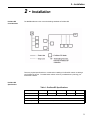


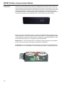
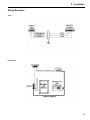

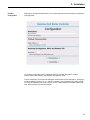


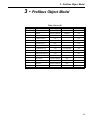
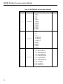
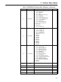
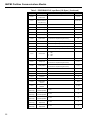
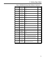
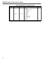

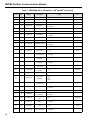
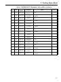

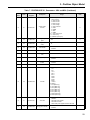

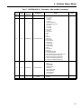
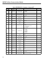
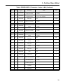
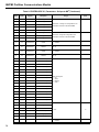
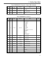
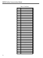


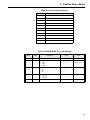

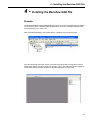
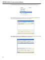

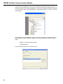


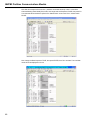
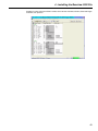
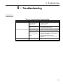

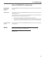

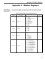
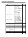
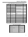


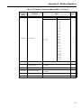

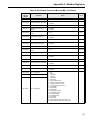

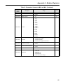
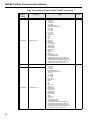
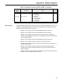

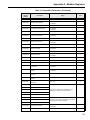
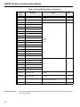


![EX MV MX3 User Manual [May16].vp](http://vs1.manualzilla.com/store/data/005646159_1-0d378a1c318c2dc00419aef6af60da73-150x150.png)