1
PUBLICATION #890023-01-02
RediStart
Solid State Starter
Software Manual
Control
The Leader In
Solid State Motor Control
Technology
© 2005 Benshaw Inc. All Rights Reserved
TRADEMARK NOTICE
are registered trademarks of Benshaw Incorporated.
Benshaw and
Modbus is a registered trademark of Schneider Electric.
UL is a trademark of Underwriters Laboratories, Incorporated
ii
WARNING
1.
This starter contains hazardous voltage that can cause electric shock
resulting in personal injury or loss of life.
2.
Before servicing, be sure all AC power is removed from the starter and
the motor has stopped spinning
3.
Wait at least 1 minute after turning off the AC power for the bus
capacitor to discharge on the control card.
4.
Do not connect or disconnect the wires to or from the starter when
power is applied.
5.
Ensure shielded cables are discharged.
WARNING
1.
Service only by qualified personnel.
2.
Make sure ground connection is in place.
3.
Make certain proper shield installation is in place.
iii
TABLE OF CONTENTS
1
INTRODUCTION................................................................................................................................................................. 1
1.1
1.2
1.3
1.4
2
USING THIS MANUAL ........................................................................................................................................................ 2
CONTACTING BENSHAW ................................................................................................................................................... 4
INSPECTION ...................................................................................................................................................................... 5
GENERAL OVERVIEW OF A REDUCED VOLTAGE STARTER ................................................................................................ 6
CONTROL CARD................................................................................................................................................................ 7
2.1 CONTROL CARD SETUP ..................................................................................................................................................... 9
2.1.1
CT Ratio Scaling....................................................................................................................................................... 9
2.1.2
CT Polarity ............................................................................................................................................................... 9
2.1.3
Confirm Switch Settings............................................................................................................................................ 9
2.1.4
Configuring the Analog Input ................................................................................................................................. 11
2.1.5
Configuring the Analog Output .............................................................................................................................. 11
2.2 BASIC CONTROL WIRING DRAWING ............................................................................................................................... 13
3
KEYPAD OPERATION..................................................................................................................................................... 15
3.1 INTRODUCTION ............................................................................................................................................................... 16
3.2 STANDARD KEYPAD AND DISPLAY ................................................................................................................................. 16
3.2.1
Viewing and Changing Parameters for the Standard Keypad................................................................................ 16
3.2.2
Special Messages Displayed................................................................................................................................... 17
3.2.3
Quick Meters........................................................................................................................................................... 18
3.2.4
Restoring Factory Parameter Settings.................................................................................................................... 19
3.2.5
Resetting a Fault..................................................................................................................................................... 19
3.2.6
Emergency Thermal Reset ...................................................................................................................................... 19
3.3 2X16 REMOTE LCD KEYPAD ......................................................................................................................................... 20
3.3.1
Description of the LEDs on the Keypad ................................................................................................................. 20
3.3.2
Description of the Keys on the Remote LCD Keypad ............................................................................................. 21
3.3.3
Alphanumeric Display ............................................................................................................................................ 22
3.3.4
Parameter Group Screens ...................................................................................................................................... 23
3.3.5
Meter Pages............................................................................................................................................................ 23
3.3.6
Fault Log Screen..................................................................................................................................................... 24
3.3.7
Fault Screen............................................................................................................................................................ 24
3.3.8
Lockout Screen........................................................................................................................................................ 24
3.3.9
Alarm Screen .......................................................................................................................................................... 25
3.3.10 Procedure for Setting Data..................................................................................................................................... 25
3.3.11 Jump Code .............................................................................................................................................................. 25
4
PARAMETERS................................................................................................................................................................... 27
4.1 INTRODUCTION ............................................................................................................................................................... 28
4.2 LED AND LCD DISPLAY PARAMETERS CROSS REFERENCE ........................................................................................... 28
4.3 LED DISPLAY PARAMETERS .......................................................................................................................................... 29
4.4 LCD DISPLAY PARAMETERS .......................................................................................................................................... 33
4.4.1
Quick Start Group................................................................................................................................................... 33
4.4.2
Control Function Group ......................................................................................................................................... 33
4.4.3
Protection Group .................................................................................................................................................... 34
4.4.4
I/O Group ............................................................................................................................................................... 35
4.4.5
Function Group ...................................................................................................................................................... 36
4.4.6
Fault Group ............................................................................................................................................................ 37
5
PARAMETER DESCRIPTIONS ...................................................................................................................................... 39
6
APPLICATIONS ................................................................................................................................................................ 89
6.1 APPLICATION CONSIDERATION BETWEEN LINE CONNECTED AND INSIDE DELTA CONNECTED SOFT STARTER .............. 90
6.1.1
Line Connected Soft Starter.................................................................................................................................... 90
6.1.2
Inside Delta Connection ......................................................................................................................................... 91
6.2 OTHER APPLICATIONS USING THE MX ........................................................................................................................... 91
iv
TABLE OF CONTENTS
6.2.1
6.2.2
6.2.3
6.2.4
7
Wye Delta ............................................................................................................................................................... 91
Phase Control ......................................................................................................................................................... 93
Current Follower .................................................................................................................................................... 93
Across The Line (Full Voltage Starter)................................................................................................................... 94
TROUBLESHOOTING ..................................................................................................................................................... 95
7.1 GENERAL TROUBLESHOOTING CHARTS .......................................................................................................................... 96
7.1.1
Motor does not start, no output to motor ................................................................................................................ 96
7.1.2
During starting, motor rotates but does not reach full speed ................................................................................. 97
7.1.3
Acceleration not operating as desired .................................................................................................................... 97
7.1.4
Deceleration not operating as desired.................................................................................................................... 98
7.1.5
Motor stops unexpectedly while running ................................................................................................................ 98
7.1.6
Metering incorrect .................................................................................................................................................. 99
7.1.7
Other Situations .................................................................................................................................................... 100
7.2 FAULT CODE TROUBLESHOOTING TABLE ..................................................................................................................... 101
8
THEORY OF OPERATION............................................................................................................................................ 109
8.1 SOLID STATE MOTOR OVERLOAD PROTECTION............................................................................................................ 110
8.1.1
Overview............................................................................................................................................................... 110
8.1.2
Setting up the MX Motor Overload....................................................................................................................... 110
8.1.3
Motor Overload Operation................................................................................................................................... 112
8.1.4
Current Imbalance / Negative Sequence Current Compensation ......................................................................... 112
8.1.5
Harmonic Compensation ...................................................................................................................................... 113
8.1.6
Hot / Cold Motor Overload Compensation........................................................................................................... 113
8.1.7
Separate Starting and Running Motor Overload Settings .................................................................................... 114
8.1.8
Motor Cooling While Stopped .............................................................................................................................. 115
8.1.9
Motor Cooling While Running.............................................................................................................................. 116
8.1.10 Emergency Motor Overload Reset........................................................................................................................ 116
8.2 MOTOR SERVICE FACTOR ............................................................................................................................................. 117
8.3 ACCELERATION CONTROL ............................................................................................................................................ 118
8.3.1
Current Ramp Settings, Ramps and Times............................................................................................................ 118
8.3.2
Programming A Kick Current............................................................................................................................... 119
8.3.3
TruTorque Acceleration Control Settings and Times ........................................................................................... 119
8.3.4
Power Control Acceleration Settings and Times .................................................................................................. 121
8.3.5
Open Loop Voltage Ramps and Times.................................................................................................................. 123
8.3.6
Dual Acceleration Ramp Control ......................................................................................................................... 125
8.4 DECELERATION CONTROL ............................................................................................................................................ 127
8.4.1
Voltage Control Deceleration............................................................................................................................... 127
8.4.2
TruTorque Deceleration ....................................................................................................................................... 128
8.5 WYE-DELTA OPERATION .............................................................................................................................................. 129
8.6 PHASE CONTROL .......................................................................................................................................................... 131
8.7 CURRENT FOLLOWER ................................................................................................................................................... 133
8.8 ACROSS THE LINE / FULL VOLTAGE OPERATION ......................................................................................................... 134
8.9 START/STOP CONTROL WITH A HAND/OFF/AUTO SELECTOR SWITCH .......................................................................... 135
8.10 SIMPLIFIED I/O SCHEMATICS ........................................................................................................................................ 136
8.11 USING MODBUS ............................................................................................................................................................ 137
9
TECHNICAL INFORMATION...................................................................................................................................... 139
9.1 GENERAL INFORMATION............................................................................................................................................... 140
9.2 ENVIRONMENTAL CONDITIONS..................................................................................................................................... 140
9.3 ALTITUDE DERATING ................................................................................................................................................... 140
9.4 APPROVALS .................................................................................................................................................................. 140
9.5 CERTIFICATE OF COMPLIANCE ...................................................................................................................................... 140
9.6 LIST OF MOTOR PROTECTION FEATURES ..................................................................................................................... 141
9.7 MX CONTROL CARD .................................................................................................................................................... 142
9.7.1
Terminal Points, Functions and Ratings .............................................................................................................. 142
9.7.2
Terminal Block Rating .......................................................................................................................................... 143
v
TABLE OF CONTENTS
9.7.3
9.7.4
Connectors, Functions and Ratings...................................................................................................................... 143
Measurements, Accuracy and Ratings.................................................................................................................. 143
10 APPENDIX........................................................................................................................................................................ 145
APPENDIX A – CE MARK........................................................................................................................................................ 147
APPENDIX B – FAULT CODES .................................................................................................................................................. 148
APPENDIX C – ALARM CODES ................................................................................................................................................ 149
APPENDIX D – MODBUS REGISTER MAP ................................................................................................................................. 151
APPENDIX E – PARAMETER TABLE ......................................................................................................................................... 162
vi
1 Introduction
1 – INTRODUCTION
Using This Manual
1.1
Using this manual
Layout
This manual is divided into 10 sections. Each section contains topics related to the section.
The sections are as follows:
1.
2.
3.
4.
5.
6.
7.
8.
9.
10.
Introduction
Control Card
Keypad Operation
Parameters
Parameter Descriptions
Applications
Troubleshooting
Theory of Operation
Technical Information
Appendices
Symbols
There are 2 symbols used in this manual to highlight important information. The symbols appear as the following:
Warning: Electrical Hazard that could result in injury or death.
Caution: Could result in damage to the starter.
Highlight: Marking an important point in the documentation.
2
1 – INTRODUCTION
Using This Manual
General Information
Benshaw offers its customers the following:
•
•
•
•
•
Start-up services
On-site training services
Technical support
Detailed documentation
Replacement parts
NOTE: Information about products and services is available by contacting Benshaw refer to Contacting Benshaw on page 4.
Start-Up Services
Benshaw technical field support personnel are available to do startup and conduct on-site training on the starter operations and
troubleshooting.
On-Site Training Services
Benshaw technical field support personnel are available to conduct on-site training on the operations and troubleshooting.
Technical Support
Benshaw technical support personnel are available (at no charge) to answer customer questions and provide technical support over
the telephone. For more information about contacting technical support personnel, refer to Contacting Benshaw on page 4.
Documentation
Benshaw provides all customers with:
•
•
•
•
•
Parameter Configuration Manual, Publication # 890023-01-xx
Hardware Manual, Publication # 890023-02-xx
Quick Start Reference Guide for LED Display, Publication # 890023-03-xx
Quick Start Reference Guide for LCD Display, Publication # 890023-04-xx
Drawing: Enclosed product has wiring diagrams of associated control devices found within the enclosure.
On-line Documentation
All documentation is available on-line at http://www.benshaw.com.
Replacement Parts
Spare and replacement parts can be purchased from Benshaw.
Software Number
This manual pertains to the software version numbers 810018-01-12, 810018-01-13, 810018-02-00
Publication History
Refer to the Revision History in the appendices.
3
1 – INTRODUCTION
Contacting Benshaw
1.2
Contacting Benshaw
Information about Benshaw products and services is available by contacting Benshaw at one of the following offices:
Benshaw Inc. Corporate Headquarters
1659 E. Sutter Road
Glenshaw, PA 15116
United States of America
Phone: (412) 487-8235
Fax: (412) 487-4201
Benshaw Canada Controls Inc.
550 Bright Street East
Listowel, Ontario N4W 3W3
Canada
Phone: (519) 291-5112
Fax: (519) 291-2595
Benshaw West
14715 North 78th Way, Suite 600
Scottsdale, AZ 85260
United States of America
Phone: (480) 905-0601
Fax: (480) 905-0757
E –Mail:
[email protected]
[email protected]
Technical support for MX starters is available at no charge by contacting Benshaw’s customer service department at one of the above
telephone numbers. A service technician is available Monday through Friday from 8:00 a.m. to 5:00 p.m. EST.
NOTE:
An on-call technician is available after normal business hours and on weekends by calling Benshaw and following the recorded
instructions.
To help assure prompt and accurate service, please have the following information available when contacting Benshaw:
•
•
•
•
•
•
•
•
•
•
•
Name of company
Telephone number where the caller can be contacted
Fax number of caller
Benshaw product name
Benshaw model number
Benshaw serial number
Name of product distributor
Approximate date of purchase
System Voltage
FLA of motor attached to Benshaw product
A brief description of the application
4
1 – INTRODUCTION
Interpreting Model Numbers
1.3
Inspection
Before storing or installing the RediStart starter with MX control, thoroughly inspect the device for possible shipping damage. Upon
receipt:
•
Remove the starter from its package and inspect exterior for shipping damage. If damage is apparent, notify the shipping agent
and your sales representative.
•
Open the enclosure and inspect the starter for any apparent damage or foreign objects. Ensure that all of the mounting hardware
and terminal connection hardware is properly seated, securely fastened, and undamaged.
•
Ensure all connections and wires are secured.
•
Read the technical data label affixed to the starter and ensure that the correct horsepower and input voltage for the application
has been purchased.
•
The starter numbering system for a chassis is:
R __ __ __ __
__ __ __ A __ __ __
Enclosures
C = Open Chassis
Frame Size
Amp Rating, (0 – 999A )
Fault Level
S = Standard
H = High
Type of Bypass
0 = None (only available with RC)
1 = Integrated
2 = Separate, Definite Purpose (Only with 1000V Starter)
3 = Separate, ATL IEC AC3 Rated
4 = Separate, ATL NEMA Rated (AC4)
Type of Control
M = Micro II Control
X = MX Control
Family of RediStart Starter
B = Bypass
C = Continuous
Example of the model Number: RBX-1S-361A-14C
A RediStart starter with bypass, MX control, Integrated Bypass, Standard Fault, 361 Amp unit, Frame 14, open Chassis
5
1 – INTRODUCTION
General Overview
1.4
General Overview of a Reduced Voltage Starter
The RediStart MX motor starter is a microprocessor-controlled starter for single or three-phase induction motors. The starter can be
custom designed for specific applications. A few of the features are:
•
•
•
•
•
•
Solid state design.
Reduced voltage starting and soft stopping.
Closed-loop motor current control, power control, torque control.
Programmable motor protection.
Programmable operating parameters.
Programmable metering.
Each starter can operate within applied line voltage and frequency values of 100VAC to 600VAC (optional 1000VAC) and 23 to
72Hz.
The starter can be programmed for any motor FLA and all of the common motor service factors. It enables operators to control both
motor acceleration and deceleration. It can also protect the motor and its load from damage that could be caused by incorrect phase
order wiring.
The starter continually monitors the amount of current being delivered to the motor. This protects the motor from overheating or
drawing excess current. The starter automatically stops the motor if the Phase to Phase line current is not within acceptable ranges or
if the current is lost in a line.
Features The enhanced engineering features of the starter include:
•
•
•
•
•
•
•
•
•
•
•
•
•
•
•
•
•
Multiple frame sizes
Universal voltage operation
Universal frequency operation
Programmable motor overload multiplier
Controlled acceleration and deceleration
Phase rotation protection
Regulated current control
Electronic motor thermal overload protection
Electronic over/under current protection
Single phase protection
Line-to-line current imbalance protection
Stalled motor protection
Programmable metering
Passcode protected
Programmable Relays
Analog output with digital offset and span adjustment
Analog input with digital offset and span adjustment
6
2 Control Card
2 – CONTROL CARD
Figure 1 – Control Card Layout
BIPC 300050-00-01
SN
120V
Control
Serial
Number
SCR 1
Gnd
Shield
Grounding
120V
Control
SCR 4
NO1
RC1
NC1
SCR 2
NO2
Relay Output
R1, R2, R3
RC2
NC2
NO3
SCR 5
RC3
NC3
START
SCR 3
DI 1
Digital Inputs
Start, DI1,
DI2, DI3
S/DI
COM
DI2
Terminating
Resistor
Conn 3
Conn 2
DI3
DI2/D3
COM
CPU Heart Beat LED
Serial Com LEDs
SCR 6
Modbus
Serial Port
Reset
Button
Analog
Input
& Config
Jumper
CT Input
CT Burden
Selector Switch
LED Display &
Keypad
Analog Output
& Config Jumper
8
2 – CONTROL CARD
2.1
Control Card Setup
2.1.1 CT Ratio Scaling
The motor current signal scaling is set according to the motor size and the application specified when the starter is ordered. To
ensure accurate operation, the motor current signal must be correctly scaled for the motor (and its application) being controlled by the
starter. Motor current signal scaling may have to be changed if:
•
Motor size has been changed from the original specification.
•
Motor load has been changed from the original application.
Motor current signal scaling is accomplished by verifying the current transformer ratio as supplied with the starter and then selecting
the correct DIP switch setting from the chart on the following page for the current transformer ratio. The DIP switches are:
Figure 2 – CT Inputs and CT switches
•
ON in the RIGHT position
•
OFF in the LEFT position
•
Refer to for Figure 1 – Control Card Layout
actual location of switches
CT Input, White wire (+)
CT Input Black wire (-)
NOTE: The applicable ratio is stamped on each CT. Adjust the DIP switches only when there is no current being supplied to the
motor, or the switches could be damaged.
NOTE: See the CT Ratio parameter on page 83.
2.1.2 CT Polarity
The CT has a polarity that must be correct for the starter to correctly measure Watts, kW Hours, Power Factor, and for the Power and
TruTorque motor control functions to operate properly.
Each CT has a dot on one side of the flat surfaces. This dot, normally white in color, must be facing in the direction of the line.
The CT can be placed either before or after the starter. In specific applications, like Inside Delta and a starter with a DC brake, the
CTs must be before the starter.
CT1 must be on Line L1 (R), CT2 must be on Line L2 (S), and CT3 must be on Line L3 (T).
2.1.3 Confirm Switch Settings
To verify or change the motor current signal scaling:
•
Compare the CT ratio stamped on each CT to the CT ratio listed on the wiring diagram supplied with the starter to ensure the
correct CTs are installed.
•
Inspect the control card to ensure that the DIP switches are in the correct positions for the applicable CT ratio and the motor
full-load Amps (FLA).
9
2 – CONTROL CARD
Table 1 – CT Ratios and Burden Switch Settings
CT Ratio
72
(4 wraps
288:1)
96
(3 wraps
288:1)
144
(2 wraps
288:1)
288
864
1320
(2 wraps
2640)
2640
2880
3900
5760
8000
14400
Mult.
CT-CT
Combinations
28800
Mult.
CT-CT
Combinations
Minimum
FLA (A rms)
2
3
4
9
3
4
5
12
4
7
8
18
8
14
16
36
24
42
50
108
37
64
76
165
73
128
151
330
73
140
165
361
105
190
225
490
160
280
330
720
223
390
465
1000
400
700
840
1800
800
1400
1680
3600
Maximum
FLA (A rms)
3
4
9
16
4
5
12
21
7
8
18
32
14
16
36
64
42
50
108
190
64
76
165
290
128
151
330
590
140
165
361
640
190
225
490
870
280
330
720
1280
390
465
1000
1800
700
840
1800
3200
1400
1680
3600
6400
10
Switch 6
Position 1
Off
Off
On
On
Off
Off
On
On
Off
Off
On
On
Off
Off
On
On
Off
Off
On
On
Off
Off
On
On
Off
Off
On
On
Off
Off
On
On
Off
Off
On
On
Off
Off
On
On
Off
Off
On
On
Off
Off
On
On
Off
Off
On
On
Switch 6
Position 2
Off
On
Off
On
Off
On
Off
On
Off
On
Off
On
Off
On
Off
On
Off
On
Off
On
Off
On
Off
On
Off
On
Off
On
Off
On
Off
On
Off
On
Off
On
Off
On
Off
On
Off
On
Off
On
Off
On
Off
On
Off
On
Off
On
2 – CONTROL CARD
2.1.4 Configuring the Analog Input
The analog input can be configured for Voltage or Current loop. The input is shipped in the Current Loop configuration unless
specified in a custom configuration. Next to the analog input terminal block is JP3. When the jumper is installed, the input is a
current loop. When removed, it is a voltage input. The control card is shipped with the jumper JP3 installed.
The analog input accepts a true differential signal through the AIN+ and AIN- terminals.
Figure 3 – Wiring Example of a Differential Voltage Analog Input
AIN
PWR
AIN+
+
AIN-
Differential
Voltage
Signal
SHLD
–
JP3 removed for
a voltage source
JP3
If the analog input is to be connected to a potentiometer, it may be powered by the AIN PWR terminal and must be grounded to the
COM terminal on the analog output terminal block. The potentiometer may be 2.5k to 10k Ohms.
Figure 4 – Wiring Example of a Potentiometer on the Analog Input
AIN
PWR
AIN+
2.5k to 10k
Pot
AINSHLD
COM
AOUT
SHLD
JP3
JP3 removed for
potentiometer on
Analog Input
NOTE: The analog output signal common also serves as the analog input signal common.
NOTE: The analog input is a low voltage input, maximum of 15VDC. The input will be damaged if control power (115VAC) or
line power is applied to the analog input.
2.1.5 Configuring the Analog Output
The analog output can be configured for Voltage or Current loop. The output is shipped in the Voltage configuration unless specified
in a custom configuration. Next to the analog output terminal block is JP1. When the jumper is installed, the output is Voltage.
When removed, it is a current loop output. The control card is shipped with the jumper installed.
NOTE: The analog output single common also serves as the analog input single common.
11
2 – CONTROL CARD
Figure 5 – MX Control Card Analog Jumper Placement
Analog Input Jumper
Analog Output Jumper
12
2 – CONTROL CARD
2.2
Basic Control Wiring Drawing
Digital inputs DI1, DI2, DI3 and relay outputs R1, R2, R3 are pre-programmed. This wiring diagram illustrates a 3-wire start/stop
control by programming DI1 as a stop input. 2-wire start/stop control can be implemented by just using the start input. Refer to
sections 5 & 6 for configuring the Digital and Analog input and output in software.
Figure 6 – Basic Wiring Diagram
13
2 – CONTROL CARD
14
3 Keypad Operation
3 – KEYPAD OPERATION
LED Keypad and Display
3.1
Introduction
The MX provides a comprehensive set of parameters to allow the use of the reduced voltage solid state starter in nearly any industrial
application. While the starter can meet the requirements of many applications right out of the box, customization of parameter values
to better suit your particular application is easily accomplished with the standard, on-board, 4-digit, 7-segment LED display/keypad.
Optionally, a 2x16 character, back-lit LCD display/keypad may be added. This optional keypad may be mounted remotely from the
MX control card. The remote LCD keypad has the same keys as the standard display with several additional keys including start and
stop keys for operation of the starter from the keypad. When the remote LCD keypad is connected, the local display is disabled.
3.2
Standard Keypad and Display
The LED display provides information on starter operation and programming. The 4-digit, 7-segment display shows starter meter
outputs and programming data. Special symbols provide further information about the starter operation (see the following section).
Figure 7 – Standard Keypad and Display
RESET
PARAM
DOW N
UP
ENTER
3.2.1 Viewing and Changing Parameters for the Standard Keypad
3.2.1.1 Viewing Parameter Values
Parameter view mode can be entered by:
1.
2.
3.
4.
5.
6.
At the default meter display, press the PARAM key to enter parameter mode. “P 1” is displayed to indicate Parameter 1.
Use the UP and DOWN keys to scroll through the available parameters.
Pressing the UP key from “P 1” advances to parameter “P 2”.
Pressing the DOWN key from “P 1” wraps around to the highest parameter.
The value of the parameter can be viewed by pressing the ENTER key.
To view another parameter without changing/saving the parameter, press the PARAM key to return to the parameter number
display.
To return to the default meter display either:
1.
2.
Press the PARAM key while in the parameter number display mode.
Wait 60 seconds and the display returns to the default meter display.
16
3 – KEYPAD OPERATION
LED Keypad and Display
3.2.1.2 Changing Parameter Values
Parameter change mode can be entered by:
1.
2.
3.
4.
5.
At the default meter display, press the PARAM key to enter parameter mode.
Use the UP and DOWN keys to scroll through the available parameters.
The value of the parameter can be viewed by pressing the ENTER key.
When viewing the parameter value, the parameter can be changed by using the UP and DOWN keys.
To store the new value, press the ENTER key. When the ENTER key is pressed the value is saved and the display goes back to
parameter # “P_”.
To exit parameter change mode without saving the new parameter value either:
1.
2.
Press the PARAM key to return to the parameter number display.
Wait 60 seconds and the display returns to the default meter display.
3.2.2 Special Messages Displayed
In addition to being able to view and change parameters, various special messages may be displayed during different conditions.
Here is a summary of the possible special messages.
No Line
Ready
Accelerating or Kicking
Accelerating or Kicking with ramp 2
Up to Speed
Run – Done with Accel ramp but not yet Up to
Speed.
Decelerating Motor
Overload Alarm – The motor overload level is
between 90% and 100%.
Overload Fault – The motor overload level has
reached 100%.
Overload Lockout – A start is not allowed until the
motor overload level cools below 15%.
Control Power Lockout – A start is not allowed
because the control power is too low.
Lock out State
xxx
xx
xx
xx
Phase order meter showing ABC
Phase order meter showing CBA
Phase order meter showing Single Phase
xxx = overload content.
xx = Parameter code.
xx = Alarm code. If the condition persists,
a fault occurs.
xx = Fault code.
Instantaneous Overcurrent
Default – Flashes when parameter defaults
are loaded.
Heater/Anti-windmill Mode
Energy Saver
In reflash mode
In reflash mode, programming
In reflash mode, verifying
In reflash mode, complete
The following sections provide more detail for some of the conditions that cause special messages to be displayed.
3.2.2.1 Power Up
The software version is displayed as a series of blinking digits once power has been applied to the MX. If the parameters were being
reset on power up, “dFLt” is flashed on the display for three seconds, and then the software version is displayed.
3.2.2.2 Stopped
When the starter is not in the run mode, the display shows the status condition of the starter, such as “rdY” (ready), “L OL”
(Overload Lockout), “noL” (No Line).
17
3 – KEYPAD OPERATION
LED Keypad and Display
3.2.2.3 Running
When running, the display shows the selected meter function. The following meters can be selected using the Meter display
parameter.
Avg. RMS current
Phase 1 RMS current
Phase 2 RMS current
Phase 3 RMS current
Current Imbalance %
GF Current (% FLA)
Avg. Voltage (RMS)
L1-L2 Voltage (RMS)
L2-L3 Voltage (RMS)
L3-L1 Voltage (RMS)
Overload %
Power Factor
KW
KVA
VARS
KWh
MWh
Phase Rotation
Line Frequency
Analog Input %
Analog Output %
Running Time Days
Running Time Hours
Starts
TruTorque %
Power %
3.2.2.4 Alarm Condition
When an alarm condition exists, the display alternates between displaying the selected meter and the alarm code. The alarm code is
displayed as “A XX”, where XX is the alarm code.
•
•
When a thermal overload alarm condition exists, “A OL” is displayed.
When a no line alarm condition exists, “noL” is displayed.
When the starter is stopped, the selected meter is not displayed.
3.2.2.5 Lockout Condition
When a lockout condition exists, the display shows the lockout code. The lockout code is displayed as “L XX”: where XX is the
lockout code. Following are the defined lockout conditions and their codes:
•
•
•
When a motor thermal overload lockout condition exists, “L OL” is displayed.
When a power stack thermal overload lockout condition exists, “L Ot” is displayed.
When a low control power lockout condition exists, “L CP” is displayed.
When there are multiple lockout codes, each is displayed at 2 second intervals.
3.2.2.6 Faulted Condition
When a fault condition exists, the display shows the fault code. The exceptions to this are as follows:
•
•
When the fault is thermal overload trip, “F OL” is displayed.
When the fault is Instantaneous Overcurrent, “ioc” is displayed.
3.2.3 Quick Meters
Although any meter may be viewed by changing the meter parameter, there are 3 “Quick Meters” that are always available with a
single key press. When the starter is in the normal display mode, the display may be toggled between the information currently
displayed and the following quick meters.
Status Meter
Toggle between the programmed meter display and the starter operational status display (rdY, run,
utS, dcL, etc) by pressing the ENTER key.
Overload Meter
Toggle between the programmed meter display and the overload content by pressing the DOWN key.
The overload is displayed as “oXXX” where XXX is the overload content. For example, when the
overload content is 76 percent, it is displayed as “o 76”.
Phase Order Meter
Toggle between the programmed meter display and the phase order by pressing the UP key. The
phase order is displayed as “AbC” or “CbA”.
18
3 – KEYPAD OPERATION
LED Keypad and Display
3.2.4 Restoring Factory Parameter Settings
To restore ALL parameters to the factory default settings, press and hold the PARAM and ENTER pushbutton switch on power up.
The display blinks “dFLt”. Parameters unique to the motor starter applications need to be set again to appropriate values before
motor operation.
3.2.5 Resetting a Fault
To reset from a fault condition, press RESET.
3.2.6 Emergency Thermal Reset
To perform an emergency thermal reset, press RESET and DOWN. This sets the motor thermal overload content to 0.
19
3 – KEYPAD OPERATION
Remote LCD Keypad and Display
3.3
2x16 Remote LCD Keypad
Like the standard keypad, the remote LCD keypad has the same basic functions with enhancements that allow using plain text instead
of codes and a menu structure instead of a straight line of parameters.
Additional keys have been added, such as “start”, “stop”, and a “left arrow” for moving the cursor around in the LCD display. Status
indicators have been added, providing additional information for the starter operation.
The remote keypad and display are connected to the MX control card via a 1 or 2 meter (3 or 6ft) cable. The remote keypad is
NEMA 1, 12, and 3R when mounted directly on a panel or the door of an enclosure with the correct gasket. If the bezel and keypad
are used, a NEMA 4 rating can be obtained. A keypad kit may be ordered from Benshaw if the starter was not originally ordered
with one. Part numbers are MX-1M-RKP-00 (includes a 1 meter cable) and MX-2M-RKP-00 (includes a 2 meter cable). Refer to
the hardware manual for mounting instructions.
Figure 8 – Remote LCD Keypad
kW
%
V
Hz
Min
A
s to p
reset
start
ST O P
ALARM
RUN
menu
enter
Starters
3.3.1 Description of the LEDs on the Keypad
The keypad provides three LED indicators in addition to the 2x16 character display. The LEDs provide starter status information.
Table 2 – 2x16 Remote Keypad LED Functions
LED
STOP
RUN
ALARM
Note:
State
On
Flashing
On
Flashing
Flashing
Indication
Stopped
Faulted
Running and up-to-speed
Running and not up-to-speed (ramping, decelling, brake, etc)
Alarm condition exists. If condition persists, a fault occurs
By default, the Stop key is always active, regardless of selected control source (Local Source and Remote Source
parameters). It may be disabled though using the Keypad Stop Disable parameter. For more information refer to page
77.
20
3 – KEYPAD OPERATION
Remote LCD Keypad and Display
3.3.2 Description of the Keys on the Remote LCD Keypad
The UP arrow, DOWN arrow, ENTER and MENU keys on the LCD keypad perform the same functions as the UP, DOWN, ENTER and
PARAM keys on the standard keypad. Three keys have been added, with one of the keys serving a dual function.
Start Key
The START key allows the starter to be started from the keypad. In order for this key to work, the
Local Source parameter must be set to Keypad (as opposed to terminal). Refer to section 5,
Parameter Descriptions.
Stop/Reset Key
When the starter is in a faulted condition, the STOP/RESET key is used to reset the fault. When the
starter is running, the STOP/RESET key causes the starter to stop.
Left Arrow
When changing a numerical parameter, the LEFT arrow key can be pressed to move the cursor to the
next significant digit. When navigating through the parameter group screens, the MENU key
progresses to the next group and the LEFT arrow key moves back to the previous group.
Table 3 – Description of the Keys on the Remote LCD Keypad
start
enter
menu
stop
reset
This key causes the starter to begin the start sequence. The direction is dependent on wiring and phase selection.
• Increase the value of a numeric parameter.
• Select the next value of an enumerated parameter.
• It scrolls forward through a list of parameter groups or parameters within a group
(When the last group or parameter is displayed, it scrolls to the beginning of the list).
• When a list of faults is displayed, it moves from one fault to the next.
• When the starter is in the Operate Mode, pressing UP allows you to change which group of meter values is
monitored.
• Decrease the value of a numeric parameter.
• Select the previous value of an enumerated parameter.
• It scrolls backward through a list of parameter groups or parameters within a group
(When the first group or parameter is displayed, it scrolls to the end of the list).
• When a list of faults is displayed, it moves from one fault to the previous fault.
• When the starter is in the Operate Mode, pressing DOWN allows you to change which group of meter values is
monitored
• When editing a numeric parameter, the LEFT arrow key moves the cursor one digit to the left. If cursor is
already at the most significant digit, it scrolls to the least significant digit on the right.
• When in Menu mode, the LEFT arrow allows groups to be scrolled through in the opposite direction of the
Menu Key.
• Stores the change of a value.
• When in Fault History, ENTER key scrolls through information logged when a fault occurred.
• Menu scrolls between the operate screen and the available parameter groups.
• When viewing a parameter, pressing MENU jumps to the top of the menu.
• When a Parameter is being edited and MENU is pressed, the change is aborted and the parameter’s old value is
displayed.
• The STOP/RESET key halts the operation of the starter (Stop Key).
• If a fault has occurred, the Stop key is used to clear the fault (Reset Key).
• The STOP/RESET key always halts the operation of the starter if the control source is set to Keypad. If the
control source is not set to the keypad, the stop key may be disabled using the Keypad Stop Disable
parameter.
21
3 – KEYPAD OPERATION
Remote LCD Keypad and Display
3.3.3 Alphanumeric Display
The remote LCD keypad and display uses a 32-character alphanumeric LCD display. All starter functions can be accessed by the
keypad. The keypad allows easy access to starter programming with parameter descriptions on the LCD display.
Power UP Screen
On power up, the software part number is displayed for a few seconds. Pressing any key immediately changes the display to the
operate screen.
Software PN
810018-01-00
NOTE: The software part number may be different than that shown above.
Operate Screen
The operate screen is the main screen. The Operate screen is used to indicate the status of the starter, if it’s running, what state it’s in,
and display the values of Meter 1 and Meter 2, which are selectable.
SSAAAAAACCCCCCCC
BBBBBBBBDDDDDDDD
The Operate Screen is divided into four sections.
•
•
•
Sections A and B display status information
Section C and D displays the meter selected by the Meter 1 and 2 parameters.
Section SS displays the source for the start command.
Table 4 – Operate Screen Section A
Display
noL
Ready
Alarm
Run
Description
L1, L2, L3 not present
Starter ready to run
A fault condition is present. If it continues, a fault to occurs
Starter is running
Table 5 – Operate Screen Section B
Display
Stopped
Lockout
Fault
Heater
Kick
Accel
Kick 2
Accel 2
Run
UTS
Control
Decel
Wye
Function
Starter is stopped and no Faults
Starter is in the Lockout condition
Starter tripped on a Fault
Starter is on and heating motor
Starter is applying kick current to the motor
Starter is Accelerating Load
Starter is applying kick current to the motor
Starter is Accelerating Load
Starter is in Run mode
Starter is Up To Speed
Phase Control or Current Follower mode
Starter is Decelerating Load
In Wye-delta control indicates motor is accelerating in Wye
mode
Table 6 – Operate Screen Section SS
K
T
S
Keypad
Terminal Block Wiring
Serial Communication Connection
22
3 – KEYPAD OPERATION
Remote LCD Keypad and Display
3.3.4 Parameter Group Screens
From the operate screen, the parameter group screens are accessed by pressing either the MENU or the LEFT arrow keys. The
parameter group screens display the different parameter groups; QST, CFN, PFN, I/O, FUN, FL_.
MMM: PPPPPPPPPPP
MI
VVVVVVVVVVV
MMM:
MI:
PPP:
VVV:
= Parameter Group
= Menu Index
= Parameter Name
= Parameter Value and Units
Refer to Section 4 for a listing of the parameters and their ranges.
3.3.5 Meter Pages
Although any meter may be viewed by changing the two meter parameters, there are 11 “Meter Pages” that are easily accessed to
view all of the meter information. These meter pages are scrolled through by pressing the UP or DOWN arrows from the operate
screen.
Current I2=
I1=
0 I3
0A
0A
Voltage V2= 480V
V1= 480 V3= 480V
MWatt Hour=
1
kWatt Hour= 356
Motor PF
VARS
=0.00
=
0
Watts
VA
=
=
TruTorque =
Power
=
0
0
0%
0%
Curr Imbal= 0.0%
Overload
Gnd Curr
=
=
12%
0%
Frequency =60.0H
Phase
=AbC
Run Days =xxxx
Run Hours =xx:xx
Analog In = 0.0%
Analog Out= 0.0%
Starts
=xxxxx
23
3 – KEYPAD OPERATION
Remote LCD Keypad and Display
Note:
Run Hours
Run days
kWatt Hours
MWatt Hours
Starts
00:00 – 23:59
0 – 2730 or 7.5 years
0 – 999
0 – 9999
0 – 65535
3.3.6 Fault Log Screen
Pressing the MENU OR the LEFT arrow keys repeatedly cycles through all of the Parameter Groups either forward or reverse. More
information regarding each fault is available through the remote LCD display than is available through the standard LED display.
FL_: Fault__
NNNNNNNNNNNNN
FL _:
Fault _ _
NNN…
= Fault Log Number. FL1 is the most recent fault and FL9 is the oldest fault.
= Fault Code
= Fault Name, or the condition when the fault occurred
Pressing the UP and DOWN keys navigates through older and newer faults in the log.
Repeatedly pressing the ENTER key rotates through the conditions the starter was in when the fault occurred.
Enter
Step
1
2
3
4
5
Fault Description
Status when the fault occurred, Run, Stopped, Accel, etc
The average current at the time of the fault
The average voltage at the time of the fault
The line frequency at the time of the fault
3.3.7 Fault Screen
When a Fault occurs, the main screen is replaced with a fault screen. The screen shows the fault number and the name of the fault.
The main status screen is not shown until the fault is reset.
When a fault occurs, the STOP LED flashes.
Fault Number
Fault Name
NOTE: For a list of the Faults, refer to Appendix B – Fault Codes on page 148.
3.3.8 Lockout Screen
When a lockout is present, the word “Lockout” is displayed on the operate screen. Pressing the ENTER key displays more
information about the Lockout.
Lockout
Overload
= 115%
Lockout
Control Power
24
3 – KEYPAD OPERATION
Remote LCD Keypad and Display
3.3.9 Alarm Screen
When an alarm is present, the word “Alarm” is displayed on the operate screen. Pressing the ENTER key displays more information
about the alarm.
Alarm Number
Alarm Name
3.3.10 Procedure for Setting Data
Select a parameter that is to be changed. To change Motor FLA from 10 Amps to 30 Amps:
From the main screen:
T Ready Ia= 0.0A
Stopped Va=
V
Press MENU key and the display shows QST: (Quick Start) screen.
QST:
00
Jump Code
1
Press UP key once to Motor FLA (QST 01).
QST: Motor FLA
01
10 Amp
Press ENTER key once, the cursor starts to flash in the one’s place.
QST: Motor FLA
01
10 Amp
Press LEFT key once, the cursor flashes in the ten’s place.
QST: Motor FLA
01
10 Amp
Press UP arrow to increase the value, for a value of 30, pressed twice.
QST: Motor FLA
01
30 Amp
Press ENTER to store the value.
QST: Motor FLA
01
30 Amp
Press UP arrow to change another parameter in QST.
Press MENU to change another parameter in another group.
Press LEFT arrow to go back to the main screen.
3.3.11 Jump Code
At the beginning of each parameter group, there is a Jump Code parameter. By changing the value of this parameter and pressing
enter, you can jump directly to any parameter within that group.
25
3 – KEYPAD OPERATION
Remote LCD Keypad and Display
26
4 Parameters
4 – PARAMETERS
4.1
Introduction
The MX incorporates a large number of parameters that allow you to configure the starter to meet the special requirements of your
particular application. The parameters are organized two ways, depending on the display being used. When the standard, on-board
LED display is used, the parameters are in a single group and numbered P1, P2, P3… etc.
When the remote LCD display is used, the parameters are divided into groups of related functionality, and within the groups the
parameters are identified by a short, descriptive name. They are numbered by the group name followed by an index within the group.
This chapter lists all of the parameters and their possible values. Section 4.3 lists the parameters in the order in which they appear on
the LED display. Section 4.4 lists them in the order in which they appear on the LCD display. The following table is a crossreference between the two.
4.2
LED and LCD Display Parameters Cross Reference
Parameter
Number
Group
P1
P2
QST 01
QST 02
P3
P4
P5
P6
P7
P8
P9
P10
P8
P6
P7
P11
P12
P13
P14
P15
P16
P17
P18
P19
P20
P21
P22
P23
P24
P25
P26
P27
P28
P29
P30
P31
P32
P33
P34
P35
QST 03
QST 04
QST 05
QST 06
QST 07
QST 08
QST 09
CFN 01
CFN 02
CFN 03
CFN 04
CFN 08
CFN 09
CFN 10
CFN 11
CFN 14
CFN 15
CFN 16
CFN 17
CFN 06
CFN 07
CFN 05
CFN 12
CFN 13
PFN 01
PFN 02
PFN 03
PFN 04
PFN 05
PFN 06
PFN 07
PFN 08
PFN 09
PFN 10
PFN 11
PFN 12
P36
PFN 13
Page
#
Parameter
Number
Group
Motor FLA
Motor Service Factor
41
41
P3
P37
PFN 14
PFN 15
Motor Running Overload Class
Local Source
Remote Source
Initial Current 1
Maximum Current 1
Ramp Time 1
Up To Speed Time
Start Mode
Ramp Time 1
Initial Current 1
Maximum Current 1
Initial Voltage/Torque/Power
Maximum Torque/Power
Kick Level 1
Kick Time 1
Stop Mode
Decel Begin Level
Decel End Level
Decel Time
Initial Current 2
Maximum Current 2
Ramp Time 2
Kick Level 2
Kick Time 2
Over Current Level
Over Current Time
Under Current Level
Under Current Time
Current Imbalance Level
Ground Fault Level
Over Voltage Level
Under Voltage Level
Voltage Trip Time
Auto Reset
Controlled Fault Stop Enable
Independent Starting/Running
Overload
Motor Starting Overload Class
42
43
44
45
46
47
48
49
47
45
46
50
51
52
52
53
54
55
56
56
57
57
57
58
58
59
60
60
61
62
63
63
64
64
64
65
P38
P39
P40
P41
P42
P43
P44
P45
P46
P47
P48
P49
P50
P51
P52
P53
P54
P55
P56
P57
P58
P59
P60
P61
P62
P63
P64
P65
P66
P67
P68
P69
NA
P70
P71
P72
PFN 16
I/O 01
I/O 02
I/O 03
I/O 04
I/O 05
I/O 06
I/O 07
I/O 08
I/O 09
I/O 10
I/O 11
I/O 12
I/O 13
I/O 14
I/O 15
I/O 16
I/O 17
PFN 17
PFN 18
FUN 15
FUN 12
FUN 11
FUN 10
FUN 09
FUN 08
FUN 07
FUN 06
FUN 05
FUN 04
FUN 03
FUN 01
FUN 02
FUN 13
FUN 14
FUN 16
66
P73
FL1
28
Page
#
Motor Running Overload Class
Motor Overload Hot/Cold
Ratio
Motor Overload Cooling Time
DI 1 Configuration
DI 2 Configuration
DI 3 Configuration
R1 Configuration
R2 Configuration
R3 Configuration
Analog Input Trip Type
Analog Input Trip Level
Analog Input Trip Time
Analog Input Span
Analog Input Offset
Analog Output Function
Analog Output Span
Analog Output Offset
Inline Configuration
Bypass Feedback Time
Keypad Stop Disable
Reserved
Reserved
Miscellaneous Commands
Communication Timeout
Communication Baud Rate
Communication Drop Number
Energy Saver
Heater Level
Starter Type
Rated Power Factor
Rated Voltage
Phase Order
CT Ratio
Meter
Meter 2
Starter Model Number
Software Part Number
Passcode
Fault Log
42
67
68
69
69
69
70
70
70
71
72
72
73
74
74
75
75
76
76
77
78
78
79
79
79
80
81
82
82
83
83
84
84
84
85
86
87
4 – PARAMETERS
4.3
LED Display Parameters
Number
P1
Parameter
Motor FLA
P2
P3
P4
P5
Motor Service Factor
Motor Running Overload Class
Local Source
Remote Source
P6
P7
P8
P9
P10
Initial Current 1
Maximum Current 1
Ramp Time 1
Up To Speed Time
Start Mode
P11
P12
P13
P14
P15
Initial Voltage/Torque/Power
Maximum Torque/Power
Kick Level 1
Kick Time 1
Stop Mode
P16
P17
P18
P19
P20
P21
P22
P23
P24
P25
P26
P27
P28
P29
P30
P31
P32
P33
P34
P35
P36
P37
P38
Decel Begin Level
Decel End Level
Decel Time
Initial Current 2
Maximum Current 2
Ramp Time 2
Kick Level 2
Kick Time 2
Over Current Level
Over Current Time
Under Current Level
Under Current Time
Current Imbalance Level
Ground Fault Level
Over Voltage Level
Under Voltage Level
Voltage Trip Time
Auto Reset
Controlled Fault Stop Enable
Independent Starting/Running Overload
Motor Starting Overload Class
Motor Overload Hot/Cold Ratio
Motor Overload Cooling Time
Setting Range
1 – 6400
1.00 – 1.99
OFF, 1 – 40
PAd: Keypad
tEr
Terminal
SEr:
Serial
50 – 600
100 – 800
0 – 300
1 – 900
oLrP: Voltage Ramp
curr:
Current Ramp
tt:
TT Ramp
Pr:
Power Ramp
1 – 100
10 – 325
OFF, 100 – 800
0.1 – 10.0
CoS
Coast
SdcL Volt Decel
tdcL
TT Decel
100 – 1
99 – 1
1 – 180
50 – 600
100 – 800
0 – 300
OFF, 100 – 800
0.1 – 10.0
OFF, 50 – 800
OFF, 0.1 – 90.0
OFF, 5 – 100
OFF, 0.1 – 90.0
OFF, 5 – 40
OFF, 5 – 100
OFF, 1 – 40
OFF, 1 – 40
0.1 – 90.0
OFF, 1– 900
OFF, On
OFF, On
OFF, 1 – 40
0 – 99
1.0 – 999.9
29
Units
RMS
Amps
Default
10
Page
41
1.15
10
tEr
41
42
43
44
%FLA
%FLA
Seconds
Seconds
100
600
15
20
curr
45
46
47
48
49
%
%
%FLA
Seconds
25
105
OFF
1.0
CoS
50
51
52
52
53
%
%
Seconds
%FLA
%FLA
Seconds
%FLA
Seconds
%FLA
Seconds
%FLA
Seconds
%
%FLA
%
%
Seconds
Seconds
40
20
15
100
600
15
OFF
1.0
OFF
0.1
OFF
0.1
15
OFF
OFF
OFF
0.1
OFF
On
OFF
10
60
30.0
54
55
56
56
57
57
57
58
58
59
60
60
61
62
63
63
64
64
64
65
66
67
68
%
Minutes
4 – PARAMETERS
Number
P39
P40
P41
P42
P43
P44
Parameter
DI 1 Configuration
DI 2 Configuration
DI 3 Configuration
Setting Range
OFF:
Off
R1 Configuration
R2 Configuration
R3 Configuration
OFF:
FLFS:
FLnF:
run:
utS:
AL:
rdyr:
LOC:
OC:
UC:
OLA:
ShFS:
ShnF:
P45
Analog Input Trip Type
P46
P47
P48
P49
P50
Analog Input Trip Level
Analog Input Trip Time
Analog Input Span
Analog Input Offset
Analog Output Function
P51
P52
P53
P54
P55
P56
P57
Analog Output Span
Analog Output Offset
Inline Configuration
Bypass Feedback Time
Keypad Stop Disable
Reserved
Reserved
Off
Fault (fail safe)
Fault (non fail
safe)
Running
UTS
Alarm
Ready
Locked Out
Over Current
Under Current
OL Alarm
Shunt Trip (fail
safe)
Shunt Trip (non
fail safe)
Ground Fault
Energy Saver
Heating
Disabled
Low Level
High Level
GfLt:
ES:
HEAt:
OFF:
Lo:
Hi:
0 – 100
0.1 – 90.0
1 – 100
0 – 99
0: OFF (no output)
1: 0 – 200% Curr
2: 0 – 800% Curr
3: 0 – 150% Volt
4: 0 – 150% OL
5: 0 – 10 kW
6: 0 – 100 kW
7: 0 – 1 MW
8: 0 – 10 MW
9: 0 – 100% Ain
10: 0 – 100% Firing
11: Calibration
1 – 125
0 – 99
OFF, 1.0 –10.0
0.1 – 5.0
Enabled, Disabled
30
Units
Default
StOP
byP
FL
Page
69
FLFS
run
utS
70
OFF
71
%
Seconds
%
%
50
0.1
100
0
0
72
72
73
74
74
%
%
Seconds
Seconds
100
0
3.0
2.0
Enabled
75
75
76
76
77
4 – PARAMETERS
Number
P58
Parameter
Miscellaneous Commands
P59
P60
P61
P62
P63
P64
Communication Timeout
Communication Baud Rate
Communication Drop Number
Energy Saver
Heater Level
Starter Type
P65
P66
Rated Power Factor
Rated Voltage
P67
Phase Order
P68
CT Ratio
Setting Range
None
Reset Run Time
Reset KWh/MWh
Enter Reflash mode
Store Parameters
Load Parameters
Factory Reset
OFF, 1 – 120
1.2, 2.4, 4.8, 9.6, 19.2
1 – 247
OFF, On
OFF, 1 – 25
nor:
Normal
Id:
Inside Delta
y-d:
Wye-Delta
PctL: Phase Control
cFol: Current Follow
AtL:
ATL
-0.01 (Lag)–1.00 (Unity)
100, 110, 120, 200, 208, 220, 230,
240, 350, 380, 400, 415, 440, 460,
480, 500, 525, 575, 600, 660, 690,
1000, 1140, 2200, 2300, 2400,
3300, 4160, 4600, 4800, 6000,
6600, 6900, 10.00 (10000), 11.00
(11000), 11.50 (11500), 12.00
(12000), 12.47 (12470), 13.20
(13200), 13.80 (13800)
InS
Insensitive
AbC
ABC
CbA
CBA
SPH
Single Phase
72, 96, 144, 288, 864,
1320, 2640, 2880, 3900,
5760, 8000, 14.4 (14400), 28.8
(28800)
Units
Default
0
Seconds
Kbps
OFF
9.6
1
OFF
OFF
nor
78
79
79
79
80
81
-0.92
480
82
82
InS
83
288
83
0:
1:
2:
3:
4
5
6:
31
%FLA
RMS
Voltage
Page
78
4 – PARAMETERS
Number
P69
P70
P71
P72
P73
Parameter
Meter
Starter Model Number
Software Part Number
Passcode
Fault Log
Setting Range
0:
Status
1:
Ave Current
2:
L1 Current
3:
L2 Current
4:
L3 Current
5:
Curr Imbal
6:
Ground Fault
7:
Ave Volts
8:
L1-L2 Volts
9:
L2-L3 Volts
10:
L3-L1 Volts
11:
Overload
12:
Power Factor
13:
Watts
14:
VA
15:
VARS
16:
kW hours
17:
MW hours
18:
Phase Order
19:
Line Freq
20:
Analog Input
21:
Analog Output
22:
Run Days
23:
Run Hours
24:
Starts
25:
TruTorque %
26:
Power %
Model Dependent
Display Only
Units
Default
1
Off
32
Page
84
84
85
86
87
4 – PARAMETERS
4.4
LCD Display Parameters
The 2x16 display has the same parameters available as the LED display, with the exception of two meter parameters instead of one
since two meters may be displayed on the main screen. The parameters are subdivided into five groups. The groups are QST (Quick
Start), CFN (Control Functions), I/O (Input/Output Functions), PFN (Protection Functions) and FUN (Function).
The Quick Start Group provides a collection of the parameters most commonly needed to be changed when commissioning a starter.
Many of the parameters in the Quick Start group are duplicates of the same parameters in other groups.
The following shows the menu structure for the LCD display as well as the text that is displayed for the parameters on the display.
4.4.1 Quick Start Group
Group
QST 00
QST 01
Display
Jump Code
Motor FLA
Description
Jump to parameter
Motor FLA
QST 02
QST 03
QST 04
QST 05
Motor SF
Running OL
Local Src
Remote Src
Motor Service Factor
Motor Running Overload Class
Local Source
Remote Source
QST 06
QST 07
QST 08
QST 09
Init Cur
Max Cur
Ramp Time
UTS Time
Initial Current 1
Maximum Current 1
Ramp Time 1
Up To Speed Time
Setting Range
1 –9
1– 6400
1.00
Off, 1
Keypad
Terminal
Serial
50
100
0
1
Units
Default
1
10
Page
1.15
10
Terminal
41
42
43
44
%FLA
%FLA
Seconds
Seconds
100
600
15
20
45
46
47
48
Units
Default
1
Current
Ramp
Page
Seconds
%FLA
%FLA
15
100
600
47
45
46
Seconds
%FLA
%FLA
%
%
%FLA
Seconds
%FLA
Seconds
15
100
600
25
105
Off
1.0
Off
1.0
Coast
57
56
57
50
51
52
52
57
58
53
%
%
Seconds
40
20
15
54
55
56
RMS
Amps
– 1.99
– 40
– 600
– 800
– 300
– 900
41
4.4.2 Control Function Group
Group
CFN 00
CFN 01
Display
Jump Code
Start Mode
Description
Jump to parameter
Start Mode
CFN 02
CFN 03
CFN 04
Ramp Time 1
Init Cur 1
Max Cur 1
Ramp Time 1
Initial Current 1
Maximum Current 1
CFN 05
CFN 06
CFN 07
CFN 08
CFN 09
CFN 10
CFN 11
CFN 12
CFN 13
CFN 14
Ramp Time 2
Init Cur 2
Max Cur 2
Init V/T/P
Max T/P
Kick Lvl 1
Kick Time 1
Kick Lvl 2
Kick Time 2
Stop Mode
Ramp Time 2
Initial Current 2
Maximum Current 2
Initial Voltage/Torque/Power
Maximum Torque/Power
Kick Level 1
Kick Time 1
Kick Level 2
Kick Time 2
Stop Mode
CFN 15
CFN 16
CFN 17
Decel Begin
Decel End
Decel Time
Decel Begin Level
Decel End Level
Decel Time
Setting Range
1 – 17
Voltage Ramp
Current Ramp
TT Ramp
Power Ramp
0 – 300
50 – 600
100 – 800
0 – 300
50 – 600
100 – 800
1 – 100
10 – 325
Off, 100 – 800
0.1 – 10.0
Off, 100 – 800
0.1 – 10.0
Coast
Volt Decel
TT Decel
100 – 1
50 – 1
1 – 180
33
49
4 – PARAMETERS
4.4.3 Protection Group
Group
PFN 00
PFN 01
PFN 02
PFN 03
PFN 04
PFN 05
PFN 06
PFN 07
PFN 08
PFN 09
PFN 10
PFN 11
PFN 12
PFN 13
PFN 14
PFN 15
PFN 16
PFN 17
PFN 18
Display
Jump Code
Over Cur
Lvl
Over Cur Tim
Undr Cur Lvl
Undr Cur Tim
Cur Imbl Lvl
Gnd Flt Lvl
Over Vlt Lvl
Undr Vlt Lvl
Vlt Trip Tim
Auto Reset
Ctrl Flt En
Indep S/R OL
Starting OL
Running OL
OL H/C Ratio
OL Cool Tim
Reserved
Reserved
Description
Jump to parameter
Over Current Level
Setting Range
1 – 18
Off, 50 – 800
Over Current Time
Under Current Level
Under Current Time
Current Imbalance Level
Ground Fault Level
Over Voltage Level
Under Voltage Level
Voltage Trip Time
Auto Reset
Controlled Fault Stop Enable
Independent Starting/Running Overload
Motor Starting Overload Class
Motor Running Overload Class
Motor Overload Hot/Cold Ratio
Motor Overload Cooling Time
Reserved
Reserved
Off, 0.1 – 90.0
Off, 5 – 100
Off, 0.1 – 90.0
Off, 5 – 40
Off, 5 – 100
Off, 1 – 40
Off, 1 – 40
0.1 – 90.0
Off, 1 – 900
Off, On
Off, On
Off, 1 – 40
Off, 1 – 40
0 – 99
1.0 – 999.9
34
Units
%FLA
Seconds
%FLA
Seconds
%
%FLA
%
%
Seconds
Seconds
%
Minutes
Default
1
Off
Page
0.1
Off
0.1
15
Off
Off
Off
0.1
Off
On
Off
10
10
60
30.0
59
60
60
61
62
63
63
64
64
64
65
66
42
67
68
58
4 – PARAMETERS
4.4.4 I/O Group
Group
I/O 00
I/O 01
I/O 02
Display
Jump Code
DI 1 Config
DI 2 Config
Description
Jump to parameter
DI 1 Configuration
DI 2 Configuration
I/O 03
DI 3 Config
DI 3 Configuration
I/O 04
I/O 05
I/O 06
R1 Config
R2 Config
R3 Config
R1 Configuration
R2 Configuration
R3 Configuration
I/O 07
Ain Trp Type
Analog Input Trip Type
I/O 08
I/O 09
I/O 10
I/O 11
I/O 12
Ain Trp Lvl
Ain Trp Tim
Ain Span
Ain Offset
Aout Fctn
Analog Input Trip Level
Analog Input Trip Time
Analog Input Span
Analog Input Offset
Analog Output Function
I/O 13
I/O 14
I/O 15
I/O 16
I/O 17
Aout Span
Aout Offset
Inline Confg
Bypas Fbk Tim
Kpd Stop Dis
Analog Output Span
Analog Output Offset
Inline Configuration
Bypass Feedback Time
Keypad Stop Disable
Setting Range
1 – 17
Off
Stop
Fault High
Fault Low
Fault Reset
Bypass Cnfrm
E OL Reset
Local/Remote
Heat Disable
Heat Enable
Ramp Select
Off
Fault FS (Fail Safe)
Fault NFS (Non Fail Safe)
Running
UTS
Alarm
Ready
Locked Out
Overcurrent
Undercurrent
OL Alarm
Shunt Trip FS
Shunt Trip NFS
Ground Fault
Energy Saver
Heating
Off
Low Level
High Level
0 – 100
0.1 – 90.0
1 – 100
0 – 99
Off
0 – 200% Curr
0 – 800% Curr
0 – 150% Volt
0 – 150% OL
0 – 10 kW
0 – 100 kW
0 – 1 MW
0 – 10 MW
0 – 100% Ain
0 – 100% Firing
Calibration
1 – 125
0 – 99
Off, 1.0 – 10.0
0.1 – 5.0
Enabled, Disabled
35
Units
Default
1
Stop
Bypass
Cnfrm
Fault
Low
Page
Fault FS
Running
UTS
70
Off
71
%
Seconds
%
%
50
0.1
100
0
Off
72
72
73
74
74
%
%
Seconds
Seconds
100
0
3.0
2.0
Enabled
75
75
76
76
77
69
4 – PARAMETERS
4.4.5 Function Group
Group
FUN 00
FUN 01
Display
Jump Code
Meter 1
Description
Jump to parameter
Meter 1
FUN 02
Meter 2
Meter 2
FUN 03
CT Ratio
CT Ratio
FUN 04
Phase Order
Phase Order
FUN 05
Rated Volts
Rated Voltage
FUN 06
FUN 07
Motor PF
Starter Type
Rated Power Factor
Starter Type
FUN 08
FUN 09
FUN 10
FUN 11
Heater Level
Energy Saver
Com Drop #
Com Baudrate
Heater Level
Energy Saver
Communication Drop Number
Communication Baud Rate
Setting Range
1 – 16
Ave Current
L1 Current
L2 Current
L3 Current
Curr Imbal
Ground Fault
Ave Volts
L1-L2 Volts
L2-L3 Volts
L3-L1 Volts
Overload
Power Factor
Watts
VA
VARS
kW hours
MW hours
Phase Order
Line Freq
Analog Input
Analog Output
Run Days
Run Hours
Starts
TruTorque %
Power %
72, 96, 144, 288, 864,
1320, 2640, 2880, 3900,
5760, 8000, 14400, 28800
Insensitive
ABC
CBA
Single Phase
100, 110, 120, 200, 208,
220, 230, 240, 350, 380,
400, 415, 440, 460, 480,
500, 525, 575, 600, 660,
690, 1000, 1140, 2200,
2300, 2400, 3300, 4160,
4600, 4800, 6000, 6600,
6900, 10000, 11000,
11500, 12000, 12470,
13200, 13800
-0.01 (Lag) – 1.00 (Unity)
Normal
Inside Delta
Wye-Delta
Phase Ctl
Curr Follow
ATL
Off, 1 – 25
Off, On
1 – 247
1200
2400
4800
9600
19200
36
Units
RMS
Voltage
%FLA
bps
Default
1
Ave
Current
Ave
Volts
Page
288
83
Insens.
83
480
82
-0.92
Normal
82
81
Off
Off
1
9600
80
79
79
79
84
4 – PARAMETERS
Group
FUN 12
FUN 13
FUN 14
FUN 15
Display
Com Timeout
Starter MN
Software PN
Misc
Command
Description
Communication Timeout
Starter Model Number
Software Part Number
Miscellaneous Commands
FUN 16
Passcode
Passcode
Setting Range
Off, 1 – 120
Model Dependent
Display Only
None
Reset RT
Reset kWh
Reflash Mode
Factory Reset
Store Parameters
Load Parameters
Units
Seconds
4.4.6 Fault Group
Group
FL1
FL2
FL3
FL4
FL5
FL6
FL7
FL8
FL9
Description
Last Fault (newest)
Previous Fault
Previous Fault
Previous Fault
Previous Fault
Previous Fault
Previous Fault
Previous Fault
Previous Fault (oldest)
Setting Range
Display Only
Display Only
Display Only
Display Only
Display Only
Display Only
Display Only
Display Only
Display Only
37
Display
Fault #
Fault #
Fault #
Fault #
Fault #
Fault #
Fault #
Fault #
Fault #
Default
Off
None
Page
78
84
85
78
Off
86
4 – PARAMETERS
38
5 Parameter Descriptions
5 – PARAMETER DESCRIPTIONS
The detailed parameter descriptions in this chapter are organized in the same order as they appear on the LED display. If the remote
LCD display is being used, the table in chapter 4 beginning on page 33 can be used to find the page number of the parameter in this
chapter.
Each parameter has a detailed description that is displayed with the following format.
P__
Parameter Name
MMM ___
LCD Display
MMM:Parameter
MI Value
Range
Parameter Value (Default ___)
Description
The description of the function
Options
LED
LCD
EEE
Keypad
See Also
Cross references to related parameters or other chapters
In the above format, the header box for the parameter contains the P number (as it appears in the menu on the LED display), the
parameter name and the parameter group number (as it appears in the menu on the LCD display).
The LCD Display section shows an example of what actually appears on the LCD display. The parameter group (represented
above by “MMM”) and the (possibly abbreviated) parameter name are shown on the first line. The parameter group number
(represented above by “MI” for “menu index”) and the parameter’s value and units are shown on the second line.
Some parameters appear in two different menus of the LCD display. This is mostly the case for those parameters that are in the
Quick Start Group. In this case, both LCD menu groups are listed in the header box and two example LCD displays are shown.
For some parameters, the Range section is enough to describe the parameter. For others, there may be an additional Options
section to describe each of the options that a parameter may be set to. The form that the options take may be different for the LED
and LCD displays, so this section shows how the options appear on both displays.
The See Also section lists cross references to other parameters that may be related as well as references to further detail in other
chapters.
40
5 – PARAMETER DESCRIPTIONS
P1
Motor FLA
QST 01
LCD Display
QST: Motor FLA
01
10 Amp
Range
Model dependent, 1 to 6400 Amps RMS (Default 10A)
Description
The Motor FLA parameter configures the motor full load amps, and is obtained from the nameplate
on the attached motor.
If multiple motors are connected, the FLA of each motor must be added together for this value.
NOTE: Incorrectly setting this parameter prevents proper operation of the motor overload
protection, motor over current protection, motor undercurrent protection, ground fault protection and
acceleration control.
P2
Motor Service Factor
QST 02
LCD Display
QST: Motor SF
02
1.15
Range
1.00 – 1.99 (Default 1.15)
Description
The Motor Service Factor parameter should be set to the service factor of the motor. The service
factor is used for the overload calculations. If the service factor of the motor is not known, then the
service factor should be set to 1.00.
NOTE: The NEC (National Electrical Code) does not allow the service factor to be set above 1.40.
Check with other local electrical codes for their requirements.
The National Electrical Code, article 430 Part C, allows for different overload multiplier factors
depending on the motor and operating conditions. NEC section 430-32 outlines the allowable service
factor for different motors.
See Also
Theory of Operation section 8.2, Motor Service Factor, on page 117
41
5 – PARAMETER DESCRIPTIONS
P3
Motor Running Overload Class
QST 03, PFN 14
LCD Display
QST: Running OL
03
10
PFN: Running OL
14
10
Range
OFF, 1– 40 (Default 10)
Description
The Motor Running Overload Class parameter sets the class for starting and running if the
Independent Starting/Running Overload parameter is set to OFF. If separate starting versus running
overload classes are desired, set the Independent Starting/Running Overload parameter to On.
The Motor Running Overload Class parameter sets the class of the electronic overload when up to
speed and stopping. The starter stores the thermal overload value as a percentage value between 0
and 100%, with 0% representing a “cold” overload and 100% representing a tripped overload. See
section 8.1, Solid State Motor Overload Protection for the overload trip time versus current curves.
When the Motor Running Overload Class parameter is set to OFF, the electronic overload is disabled
when up to speed and a separate motor overload protection device must be supplied.
NOTE: Care must be taken not to damage the motor when turning the running overload class off or
setting a high value.
NOTE: Consult motor manufacturer data to determine the correct motor overload settings.
See Also
Independent Starting/Running Overload parameter on page 65
Motor Starting Overload Class parameter on page 66
Motor Overload Hot/Cold Ratio parameter on page 67
Motor Overload Cooling Time parameter on page on page 68
Relay Output Configuration parameter on page 70
Theory of Operation section 8.1, Solid State Motor Overload Protection, on page 110
42
5 – PARAMETER DESCRIPTIONS
P4
Local Source
QST 04
LCD Display
QST:Local Src
04 Terminal
Range
PAd, tEr, SEr (Default tEr)
Description
The MX can have three sources of start and stop control; Terminal, Keypad and Serial. Two
parameters, Local Source and Remote Source, select the source of the start and stop control.
If a digital input is programmed as “L-r” (Local / Remote), then that input selects the control source.
When the input is low, the local source is used. When the input is high, the remote source is used. If
no digital input is programmed as “L-r”, then the local/remote bit in the starter control Modbus
register selects the control source. The default value of the bit is Local (0).
Options
See Also
LED
LCD
PAd
Keypad
When selected, the start/stop control is from the keypad.
tEr
Terminal
When selected, the start/stop control is from the terminal strip inputs.
SEr
Serial
When selected, the start/stop control is from the network.
Remote Source parameter on page 44
Digital Input Configuration parameters on page 69
Keypad Stop Disable parameter on page 77
Communication Timeout parameter on page 78
Communication Baud Rate parameter on page 79
Communication Drop Number parameter on page 79
NOTE: By default, the Stop key is always active, regardless of selected control source. It may be
disabled though using the Keypad Stop Disable parameter.
43
5 – PARAMETER DESCRIPTIONS
P5
Remote Source
QST 05
LCD Display
QST:Remote SRC
05 Terminal
Range
PAd, tEr, SEr (Default tEr)
Description
The MX can have three sources of start and stop control; Terminal, Keypad and Serial. Two
parameters, Local Source and Remote Source, select the source of the start and stop control.
If a digital input is programmed as “L-r” (Local / Remote), then that input selects the control source.
When the input is low, the local source is used. When the input is high, the remote source is used. If
no digital input is programmed as “L-r”, then the local/remote bit in the starter control Modbus
register selects the control source. The default value of the bit is Local (0).
Options
See Also
LED
LCD
PAd
Keypad
When selected, the start/stop control is from the keypad.
tEr
Terminal
When selected, the start/stop control is from the terminal strip inputs.
SEr
Serial
When selected, the start/stop control is from the network.
Local Source parameter on page 43
Digital Input Configuration parameters on page 69
Keypad Stop Disable parameter on page 77
Communication Timeout parameter on page 78
Communication Baud Rate parameter on page 79
Communication Drop Number parameter on page 79
Figure 9 – Local Remote Source
Local Source
Keypad
•
Terminal
•
Serial
•
Starter
Source
Remote Source
Keypad
•
Terminal
•
Serial
•
L-r Input, DI1-DI3,
configured by Parameter
P39,P40,P41/
I/O01, I/O02, I/O03
44
5 – PARAMETER DESCRIPTIONS
P6
Initial Current 1
QST 06, CFN 03
LCD Display
QST:
06
Init Cur 1
100 %
CFN:
03
Init Cur 1
100 %
Range
50 – 600 % of FLA (Default 100%)
Description
The Initial Current 1 parameter is set as a percentage of the motor FLA parameter setting. The Initial
Current 1 parameter sets the current that is initially supplied to the motor when a start is commanded.
The initial current should be set to the level that allows the motor to begin rotating within a couple of
seconds of receiving a start command.
To adjust the initial current setting, give the starter a run command. Observe the motor to see how
long it takes before it begins rotating and then stop the unit. For every second that the motor doesn’t
rotate, increase the initial current by 20%. Typical loads require an initial current in the range of 50%
to 175%.
If the motor does not rotate within a few seconds after a start command, the initial current should be
increased. If the motor takes off too quickly after a start command, the initial current should be
decreased.
The Initial Current 1 parameter must be set to a value that is lower than the Maximum Current 1
parameter setting.
See Also
Maximum Current 1 parameter on page 46
Ramp Time 1 parameter on page 47
Kick Level 1 parameter on page 52
Kick Time 1 parameter on page 52
Start Mode parameter on page 49
Theory of Operation section 8.3.1, Current Ramp Settings, Ramps and Times, on page 118
45
5 – PARAMETER DESCRIPTIONS
P7
Maximum Current 1
QST 07, CFN 04
LCD Display
QST:
07
Max Cur 1
600 %
CFN:
04
Max Cur 1
600 %
Range
100 – 800 % of FLA (Default 600%)
Description
The Maximum Current 1 parameter is set as a percentage of the motor FLA parameter setting. The
Maximum Current 1 parameter performs two functions. It sets the current level for the end of the
ramp profile. It also sets the maximum current that is allowed to reach the motor after the ramp is
completed.
If the ramp time expires before the motor has reached full speed, the starter holds the current at the
maximum current level until the UTS timer expires, the motor reaches full speed, or the overload
trips.
Typically, the maximum current is set to 600% unless the power system or load dictates the setting of
a lower maximum current.
See Also
Initial Current 1 parameter on page 45
Ramp Time 1 parameter on page 47
Up To Speed Time parameter on page 48
Kick Level 1 parameter on page 52
Kick Time 1 parameter on page 52
Start Mode parameter on page 49
Theory of Operation section 8.3.1, Current Ramp Settings, Ramps and Times, on page 118
46
5 – PARAMETER DESCRIPTIONS
P8
Ramp Time 1
QST 08, CFN02
LCD Display
QST: Ramp Time 1
08
15 sec
CFN: Ramp Time 1
02
15 sec
Range
0 – 300 seconds (Default 15 seconds)
Description
The Ramp Time 1 parameter is the time it takes for the starter to allow the current, voltage, torque or
power (depending on the start mode) to go from its initial to the maximum value. To make the motor
accelerate faster, decrease the ramp time. To make the motor accelerate slower, increase the ramp
time.
A typical ramp time setting is from 15 to 30 seconds.
If the ramp time expires before the motor reaches full speed, the starter maintains the maximum
current level until either the motor reaches full speed, the UTS timer expires, or the motor thermal
overload trips.
NOTE: Setting the ramp time to a specific value does not necessarily mean that the motor will take
this time to accelerate to full speed. The motor and load may achieve full speed before the ramp time
expires if the application does not require the set ramp time and maximum current to reach full speed.
Alternatively, the motor and load may take longer than the set ramp time to achieve full speed.
See Also
Initial Current 1 parameter on page 45
Maximum Current 1 parameter on page 46
Up To Speed Time parameter on page 48
Kick Level 1 parameter on page 52
Kick Time 1 parameter on page 52
Start Mode parameter on page 49
Theory of Operation section 8.3.1, Current Ramp Settings, Ramps and Times, on page 118
47
5 – PARAMETER DESCRIPTIONS
P9
Up To Speed Time
QST 09
LCD Display
QST:
09
UTS Time
20 sec
Range
1– 900 Seconds (Default 20 sec)
Description
The Up To Speed Time parameter sets the maximum acceleration time to full speed that the motor
can take. A stalled motor condition is detected if the motor does not get up-to-speed before the up-tospeed timer expires. This allows the programming of a maximum acceleration time for the motor.
The motor is considered up-to-speed once the current stabilizes below 175 percent of the FLA value
and the ramp time expires.
NOTE: During normal acceleration ramps, the up-to-speed timer has to be greater than the sum of
the highest ramp time in use and the kick time. The up-to-speed timer does not automatically change
to be greater than the ramp time. If a ramp time greater than the up-to-speed timer is set, the starter
will declare an up-to-speed fault every time a start is attempted.
NOTE: When the Start Mode parameter is set to Open-Loop Voltage Ramp, the UTS timer acts as
an acceleration kick. When the UTS timer expires, full voltage is applied to the motor. This feature
can be used to reduce motor oscillations if they occur near the end of an open loop voltage ramp start.
NOTE: When the Starter Type parameter is set to Wye-Delta, the UTS timer is used as the transition
timer. When the UTS timer expires, the transition from Wye starting mode to Delta running mode
takes place.
Fault Code 01 - Up to Speed Fault is declared when a stalled motor condition is detected.
See Also
Ramp Time 1 parameter on page 47
Kick Time 1 parameter on page 52
Ramp Time 2 parameter on page 57
Kick Time 2 parameter on page 58
Start Mode parameter on page 49
Starter Type parameter on page 81
Application section 6.2.1, Wye Delta, on page 91
Theory of Operation section 8.3, Acceleration Control, on page 118
48
5 – PARAMETER DESCRIPTIONS
P10
Start Mode
CFN 01
LCD Display
CFN: Start Mode
01 Current Ramp
Range
OLrP, Curr, tt, Pr (Default Curr)
Description
The Start Mode parameter allows the selection of the optimal starting ramp profile based on the
application.
Options
LED
LCD
OLrP:
Voltage Ramp
Open Loop Voltage acceleration ramp
Curr:
Current Ramp
Current control acceleration ramp. The closed loop current control
acceleration ramp is ideal for starting most general-purpose motor
applications. Examples: crushers, ball mills, reciprocating
compressors, saws, centrifuges, and most other applications.
tt:
TT Ramp
TruTorque control acceleration ramp. The closed loop TruTorque
control acceleration ramp is suitable for applications that require a
minimum of torque transients during starting or for consistently loaded
applications that require a reduction of torque surges during starting.
Examples: centrifugal pumps, fans, and belt driven equipment.
Pr:
Power Ramp
Power (kW) control acceleration ramp. The closed loop power control
acceleration ramp is ideal for starting applications using a generator or
other limited capacity source.
See Also
Initial Current 1 parameter on page 45
Maximum Current 1 parameter on page 46
Ramp Time 1 parameter on page 47
Kick Level 1 parameter on page 52
Kick Time 1 parameter on page 52
Initial Voltage/Torque/Power parameter on page 50
Theory of Operation section 8.3, Acceleration Control, on page 118
49
5 – PARAMETER DESCRIPTIONS
P11
Initial Voltage/Torque/Power
CFN 08
LCD Display
CFN:Init V/T/P
08
25 %
Range
1 – 100 % of Voltage/Torque/Power (Default 25%)
Description
Start Mode set to Open Loop Voltage Acceleration:
When the Start Mode parameter is set to open-loop voltage acceleration, this parameter sets the
starting point for the voltage acceleration ramp profile. A typical value is 25%. If the motor starts
too quickly or the initial current is too high, reduce this parameter. If the motor does not start rotating
within a few seconds after a start is commanded, increase this parameter.
Start Mode set to Current Control Acceleration:
Not used when the Start Mode parameter is set to Current control acceleration. Refer to the Initial
Current 1 parameter to set the initial current level.
Start Mode set to TruTorque Control Acceleration:
When the Start Mode parameter is set to TruTorque acceleration, this parameter sets the initial torque
level that the motor produces at the beginning of the starting ramp profile. A typical value is 10% to
20%. If the motor starts too quickly or the initial torque level is too high, reduce this parameter. If
the motor does not start rotating within a few seconds after a start is commanded, increase this
parameter. If the value is set too low a “No Current at Run” fault may occur during acceleration.
Note: It is important that the Rated Power Factor parameter is set properly so that the actual initial
torque level is the value desired.
Start Mode set to Power Control Acceleration:
When the Start Mode parameter is set to Power controlled acceleration, this parameter sets the initial
motor power (KW) level that will be achieved at the beginning of the starting ramp profile. A typical
value is 10% to 30%. If the motor starts too quickly or the initial power level is too high, reduce this
parameter. If the motor does not start rotating within a few seconds after a start is commanded,
increase this parameter. If the value is set too low a “No Current at Run” fault may occur during
acceleration.
Note: It is important that the Rated Power Factor parameter is set properly so that the actual initial
power level is the value desired.
See Also
Maximum Torque/Power parameter on page 51
Initial Current 1 parameter on page 45
Ramp Time 1 parameter on page 47
Start Mode parameter on page 49
Rated Power Factor parameter on page 82
Theory of Operation section 8.3, Acceleration Control, on page 118
50
5 – PARAMETER DESCRIPTIONS
P12
Maximum Torque/Power
CFN 09
LCD Display
CFN:Max T/P
09
105 %
Range
10 – 325 % of Torque/Power (Default 105%)
Description
Start Mode set to Open Loop Voltage Acceleration:
Not used when the Start Mode parameter is set to open-loop voltage acceleration. When in open loop
voltage acceleration mode, the final voltage ramp value is always 100% or full voltage.
Start Mode set to Current Control Acceleration:
Not used when the Start Mode parameter is set to Current control acceleration mode. Refer to the
Maximum Current 1 parameter to set the maximum current level.
Start Mode set to TruTorque Control Acceleration:
When the Start Mode parameter is set to TruTorque acceleration, this parameter sets the final or
maximum torque level that the motor produces at the end of the acceleration ramp time. For a loaded
motor, the maximum torque value initially should be set to 100% or greater. If the maximum torque
value is set too low, the motor may not produce enough torque to reach full speed and may stall. On
lightly loaded motors, this parameter may be reduced below 100% to produce smoother starts.
Note: It is important that the Rated Power Factor parameter is set properly so that the desired
maximum torque level is achieved.
Start Mode set to Power Control Acceleration:
When the Start Mode parameter is set to Power controlled acceleration, this parameter sets the final
or maximum power (KW) consumption level that will be achieved at the end of the ramp time. For a
loaded motor, the maximum power value initially should be set to 100% or greater. If the maximum
power level is set too low, the motor may not produce enough torque to reach full speed and may
stall. On lightly loaded motors, this parameter may be reduced below 100% to provide for smoother
starts.
Note: It is important that the Rated Power Factor parameter is set properly so that the actual
maximum power level is achieved.
See Also
Initial Voltage/Torque/Power parameter on page 50
Maximum Current 1 parameter on page 46
Ramp Time 1 parameter on page 47
Start Mode parameter on page 49
Rated Power Factor parameter on page 82
Theory of Operation section 8.3, Acceleration Control, on page 118
51
5 – PARAMETER DESCRIPTIONS
P13
Kick Level 1
CFN 10
LCD Display
CFN: Kick Lvl 1
10
Off
Range
OFF, 100 – 800% of FLA (Default OFF)
Description
The Kick Level 1 parameter sets the current level that precedes any ramp when a start is first
commanded. The kick current is only useful on motor loads that are hard to get rotating but then are
much easier to move once they are rotating. An example of a load that is hard to get rotating is a ball
mill. The ball mill requires a high torque to get it to rotate the first quarter turn (90°). Once the ball
mill is past 90° of rotation, the material inside begins tumbling and it is easier to turn.
The kick level is usually set to a low value and then the kick time is adjusted to get the motor
rotating. If the kick time is set to more than 2.0 seconds without the motor rotating, increase the kick
current by 100% and re-adjust the kick time.
See Also
P14
Kick Time 1 parameter on page 52
Start Mode parameter on page 49
Theory of Operation section 8.3.2, Programming A Kick Current, on page 119
Kick Time 1
CFN 11
LCD Display
CFN: Kick Time 1
11
1.0 sec
Range
0.1 – 10.0 seconds (Default 1.0 sec)
Description
The Kick Time 1 parameter sets the length of time that the kick current level is applied to the motor.
The kick time adjustment should begin at 0.5 seconds and be adjusted by 0.1 or 0.2 second intervals
until the motor begins rotating. If the kick time is adjusted above 2.0 seconds without the motor
rotating, start over with a higher kick current setting.
NOTE: The kick time adds to the total start time and must be accounted for when setting the UTS
time.
See Also
Kick Level 1 parameter on page 52
Start Mode parameter on page 49
Up To Speed Time parameter on page 48
Theory of Operation section 8.3.2, Programming A Kick Current, on page 119
52
5 – PARAMETER DESCRIPTIONS
P15
Stop Mode
CFN 14
LCD Display
CFN: Stop Mode
14
Coast
Range
CoS, SdcL, tdcL (Default CoS)
Description
The Stop Mode parameter allows for the most suitable stop of the motor based on the application.
Options
LED
LCD
CoS
Coast
Coast: A coast to stop should be used when no special stopping
requirements are necessary; Example: crushers, balls mills,
centrifuges, belts, conveyor. In Low Voltage systems, the bypass
contactor is opened before the SCRs stop gating to reduce wear on the
contactor contacts. (Default)
SdcL
Voltage Decel
Voltage Decel: In this mode, the starter linearly phases-back the SCRs
based on the parameters Decel Begin Level, Decel End Level, and
Decel Time.
tdcL
TT Decel
TruTorque Decel: In this mode, the starter linearly reduces the motor
torque based on the Decel End Level and Decel Time.
Note: The MX stops the motor when any fault occurs. Depending on the application, it may be
desirable for the motor to be stopped in a controlled manner (Voltage Decel or TT Decel) instead of
being allowed to coast to a stop when this occurs. This may be achieved by setting the Controlled
Fault Stop Enable parameter to On. Be aware however that not all fault conditions allow for a
controlled fault stop.
See Also
Decel Begin Level parameter on page 54
Decel End Level parameter on page 55
Decel Time parameter on page 56
Controlled Fault Stop Enable parameter on page 64
Theory of Operation section 8.4, Deceleration Control, on page 127
53
5 – PARAMETER DESCRIPTIONS
P16
Decel Begin Level
CFN 15
LCD Display
CFN:Decel Begin
15
40 %
Range
1 % - 100% of phase angle firing (Default 40%)
Description
Stop Mode set to Voltage Deceleration:
The voltage deceleration profile utilizes an open loop S-curve voltage ramp profile. When the Stop
Mode parameter is set to Voltage Decel, the Decel Begin Level parameter sets the initial or starting
voltage level when transferring from running to deceleration. The deceleration beginning level is not
a precise percentage of actual line voltage, but defines a point on the S-curve deceleration profile.
A typical voltage decel begin level setting is between 30% and 40%. If the motor initially surges
(oscillates) when a stop is commanded, decrease this parameter value. If there is a sudden drop in
motor speed when a stop is commanded, increase this parameter value.
Stop Mode set to TruTorque Deceleration:
Not used when the Stop Mode parameter is set to TruTorque Decel, the decel begin level has no
effect on the deceleration profile. The TruTorque beginning deceleration level is automatically
calculated based on the motor load at the time the stop command is given.
Note: It is important that the Rated Power Factor parameter is set properly so that the actual
deceleration torque levels are the levels desired.
See Also
Stop Mode parameter on page 53
Decel End Level parameter on page 55
Decel Time parameter on page 56
Controlled Fault Stop Enable parameter on page 64
Rated Power Factor parameter on page 82
Theory of Operation section 8.4, Deceleration Control, on page 127
54
5 – PARAMETER DESCRIPTIONS
P17
Decel End Level
CFN 16
LCD Display
CFN:
16
Decel End
20 %
Range
99 – 1 % of phase angle firing (Default 20%)
Description
Stop Mode set to Voltage Deceleration:
The voltage deceleration profile utilizes an open loop S-curve voltage ramp profile. When the Stop
Mode parameter is set to Voltage Decel, the Decel End Level parameter sets the ending voltage level
for the voltage deceleration ramp profile. The deceleration ending level is not a precise percentage of
actual line voltage, but defines an ending point on the S-curve deceleration profile.
Note: The deceleration end level can not be set greater than the decel begin level.
A typical voltage decel end level setting is between 10% and 20%. If the motor stops rotating before
the deceleration time has expired, increase this parameter value. If the motor is still rotating when the
deceleration time has expired, decrease this parameter value. If the value is set too low a “No
Current at Run” fault may occur during deceleration.
Stop Mode set to TruTorque Deceleration:
When the Stop Mode parameter is set to TruTorque Decel, the decel end level parameter sets the
ending torque level for the TruTorque deceleration ramp profile.
A typical TruTorque decel end level setting is between 10% and 20%. If the motor stops rotating
before the deceleration time has expired, increase this parameter value. If the motor is still rotating
when the deceleration time has expired, decrease this parameter value.
See Also
Stop Mode parameter on page 53
Decel Begin Level parameter on page 54
Decel Time parameter on page 56
Controlled Fault Stop Enable parameter on page 64
Theory of Operation section 8.4, Deceleration Control, on page 127
55
5 – PARAMETER DESCRIPTIONS
P18
Decel Time
CFN 17
LCD Display
CFN: Decel Time
17
15 sec
Range
1 – 180 seconds (Default 15 sec)
Description
The Decel Time parameter sets the time that the deceleration profile is applied to the motor and sets
the slope of the deceleration ramp profile. When in voltage decel mode, this time sets the time
between applying the initial decel level to the application of the final decel level.
Note: If the motor is not up to speed when a stop is commanded, the voltage decel profile begins at
the lower of either the decel begin level setting or at the motor voltage level when the stop is
commanded. Although the profile may be adjusted, the deceleration time remains the same.
When in the TruTorque deceleration mode, the decel time sets the time between when a stop is
commanded and when the decel end torque level is applied.
If the motor stops rotating before the decel time expires, decrease the decel time parameter. If the
motor is still rotating when the decel time expires, increase the decel time parameter.
A typical decel time is 20 to 40 seconds.
Note: Depending on the motor load and the decel parameter settings, the motor may or may not be
fully stopped at the end of the deceleration time.
Refer to section 8.4, Deceleration Control page 127,
See Also
P19
Stop Mode parameter on page 53
Decel Begin Level parameter on page 54
Decel End Level parameter on page 55
Controlled Fault Stop Enable parameter on page 64
Theory of Operation section 8.4, Deceleration Control, on page 127
Initial Current 2
CFN 06
LCD Display
CFN:
06
Init Cur 2
100 %
Range
50 – 600 % of FLA (Default 100%)
Description
The Initial Current 2 parameter is set as a percentage of the motor FLA parameter setting when the
second ramp is active. Refer to the Initial Current 1 parameter for description of operation.
See Also
Initial Current 1 parameter on page 45
Digital Input Configuration parameters on page 69
Theory of Operation section 8.3.1, Current Ramp Settings, Ramps and Times, on page 118
Theory of Operation section 8.3.6, Dual Acceleration Ramp Control, on page 125
56
5 – PARAMETER DESCRIPTIONS
P20
Maximum Current 2
CFN 07
LCD Display
CFN:
07
Max Cur 2
600 %
Range
100 – 800 % of FLA (Default 600%)
Description
The Maximum Current 2 parameter is set as a percentage of the motor FLA parameter setting, when
the second ramp is active. Refer to the Maximum Current 1 for description of operation.
See Also
Maximum Current 1 parameter on page 46
Digital Input Configuration parameters on page 69
Theory of Operation section 8.3.1, Current Ramp Settings, Ramps and Times, on page 118
Theory of Operation section 8.3.6, Dual Acceleration Ramp Control, on page 125
P21
Ramp Time 2
CFN 05
LCD Display
CFN: Ramp Time 2
05
15 sec
Range
0 – 300 seconds (Default 15 seconds)
Description
The Ramp Time 2 parameter the time it takes for the starter to allow the current to go from the initial
current to the maximum current when the second ramp is active. Refer to the Ramp Time 1
parameter for description of operation.
See Also
Ramp Time 1 parameter on page 47
Digital Input Configuration parameters on page 69
Theory of Operation section 8.3.1, Current Ramp Settings, Ramps and Times, on page 118
Theory of Operation section 8.3.6, Dual Acceleration Ramp Control, on page 125
P22
Kick Level 2
CFN 12
LCD Display
CFN: Kick Lvl 2
12
Off
Range
OFF, 100 – 800% of FLA (Default OFF)
Description
The Kick Level 2 parameter sets the current level that precedes any ramp when a start is first
commanded when the second ramp is active. Refer to the Kick Level 1 parameter for description of
operation.
See Also
Kick Level 1 parameter on page 52
Digital Input Configuration parameters on page 69
Theory of Operation section 8.3.2, Programming A Kick Current, on page 119
Theory of Operation section 8.3.6, Dual Acceleration Ramp Control, on page 125
57
5 – PARAMETER DESCRIPTIONS
P23
Kick Time 2
CFN 13
LCD Display
CFN: Kick Time 2
13
1.0 sec
Range
0.1 – 10.0 seconds (Default 1.0 sec)
Description
The Kick Time 2 parameter sets the length of time that the kick current level is applied to the motor
when the second ramp is active. Refer to the Kick Time 1 parameter for description of operation.
See Also
Kick Time 1 parameter on page 52
Digital Input Configuration parameters on page 69
Theory of Operation section 8.3.2, Programming A Kick Current, on page 119
Theory of Operation section 8.3.6, Dual Acceleration Ramp Control, on page 125
P24
Over Current Level
PFN 01
LCD Display
PFN:Over Cur Lvl
01
Off
Range
OFF, 50 – 800 % of FLA (Default OFF)
Description
If the starter detects a one cycle, average RMS current that is greater than the level defined, an over
current alarm condition exists and the alarm relay energizes if defined. The over current timer starts
a delay time. If the over current still exists when the delay timer expires, the starter Over Current
Trips (F31) and the fault relay de-energizes.
The Over Current Trip is only active in the UTS state, Energy Saver state, Current follower or while
in the Phase Control mode.
A relay can be programmed to change state when an over current alarm condition is detected.
See Also
Over Current Time parameter on page 59
Relay Output Configuration parameters on page 70
Auto Reset parameter on page 64
Controlled Fault Stop Enable parameter on page 64
% Current
Alarm
Condition
Fault
Trip
Over Cur Lvl
PFN 01/P24
Motor FLA
QST 01/P1
Time
Delay
PFN 02/P25
58
5 – PARAMETER DESCRIPTIONS
P25
Over Current Time
PFN 02
LCD Display
PFN:Over Cur Tim
02
0.1 sec
Range
Off, 0.1 – 90.0 seconds (Default 0.1 sec)
Description
The Over Current Time parameter sets the period of time that the motor current must be greater than
the Over Current Level parameter before an over current fault and trip occurs.
If OFF is selected, the over current timer does not operate and the starter does not trip. It energizes
any relay set to Overcurrent until the current drops or the starter trips on an overload.
A shear pin function can be implemented by setting the delay to its minimum value.
See Also
Over Current Level parameter on page 58
Relay Output Configuration parameters on page 70
Auto Reset parameter on page 64
Controlled Fault Stop Enable parameter on page 64
59
5 – PARAMETER DESCRIPTIONS
P26
Under Current Level
PFN 03
LCD Display
PFN:Undr Cur Lvl
03
Off
Range
OFF, 5 – 100 % of FLA (Default OFF)
Description
If the MX detects a one cycle, average RMS current that is less than the level defined, an under
current alarm condition exists and the alarm relay energizes, if defined. The under current timer
starts a delay time. If the under current still exists when the delay time expires, the starter Under
Current Trips (F34) and the fault relay de-energizes.
The Under Current Trip is only active in the UTS state, Energy Saver state, Current follower or while
in the Phase Control mode.
A relay can be programmed to change state when an under current alarm condition is detected.
See Also
Under Current Time parameter on page 60
Relay Output Configuration parameters on page 70
Auto Reset parameter on page 64
Controlled Fault Stop Enable parameter on page 64
% Current
Alarm
Condition
Fault
Trip
Motor FLA
QST 01/P1
Under Cur Lvl
PFN 03/P26
Time
Delay
PFN 04/P27
P27
Under Current Time
PFN 04
LCD Display
PFN:Undr Cur Tim
04
0.1 sec
Range
Off, 0.1 – 90.0 seconds (Default 0.1 sec)
Description
The Under Current Time parameter sets the period of time that the motor current must be less than
the Under Current Level parameter before an under current fault and trip occurs.
If OFF is selected, the under current timer does not operate and the starter does not trip. It energizes
any relay set to Undercurrent until the current rises.
See Also
Under Current Level parameter on page 60
Relay Output Configuration parameters on page 70
Auto Reset parameter on page 64
Controlled Fault Stop Enable parameter on page 64
60
5 – PARAMETER DESCRIPTIONS
P28
Current Imbalance Level
PFN 05
LCD Display
PFN:Cur Imbl Lvl
05
15%
Range
OFF, 5 – 40 % (Default 15%)
Description
The Current Imbalance Level parameter sets the imbalance that is allowed before the starter shuts
down. The current imbalance must exist for 10 seconds before a fault occurs.
At average currents less than or equal to full load current (FLA), the current imbalance for each phase
is calculated as the percentage difference between the phase current that has the maximum deviation
from the average current (Imax) and the FLA current.
The equation for the current imbalance if running at current <=FLA:
% imbalance =
(I ave - I max )
x 100%
FLA
At average currents greater than full load current (FLA), the current imbalance for each phase is
calculated as the percentage difference between the phase current that has the maximum deviation
from the average current (Imax) and the average current (Iave).
The equation for the current imbalance if running at current > FLA:
% imbalance =
(I ave - I max )
x 100%
I ave
If the highest calculated current imbalance is greater than the current imbalance level for 10 seconds,
the starter shuts down the motor and declares a Fault 37 (Current Imbalance).
See Also
Auto Reset parameter on page 64
Controlled Fault Stop Enable parameter on page 64
Alarm
Condition
% Imbalance
Fault
Trip
Current Imbl Lvl
PFN 05/P28
Time
Delay
(Fixed 10 Seconds)
61
5 – PARAMETER DESCRIPTIONS
P29
Ground Fault Level
PFN 06
LCD Display
PFN:Gnd Flt Lvl
06
Off
Range
OFF, 5 – 100 % FLA (Default OFF)
Description
The Ground Fault Level parameter sets a ground fault current trip or indicate level that can be used to
protect the system from a ground fault condition. The starter monitors the instantaneous sum of the
three line currents to detect the ground fault current.
The ground fault current has to remain above the ground fault level for 3 seconds before the starter
recognizes a ground fault condition. Once the starter recognizes a ground fault condition, it shuts
down the motor and declares a Fault 38 (Ground Fault).
If a programmable relay is set to ground fault (GND), the starter energizes the relay when the
condition exists.
A typical value for the ground fault current setting is 10% to 20% of the full load amps of the motor.
Alarm
Condition
% Current
Fault
Trip
Gnd Flt Lvl
PFN 06/P29
Time
Delay
(Fixed 3 seconds)
NOTE: This is often referred to as residual ground fault protection. This type of protection is meant
to provide machine ground fault protection only. It is not meant to provide human ground fault
protection.
NOTE: The MX residual ground fault protection function is meant to detect ground faults on solidly
grounded systems. Use on a high impedance or floating ground power system may impair the
usefulness of the MX residual ground fault detection feature.
NOTE: Due to uneven CT saturation effects and motor and power system variations, there may be
small values of residual ground fault currents measured by the MX during normal operation.
See Also
Relay Output Configuration parameters on page 70
Auto Reset parameter on page 64
Controlled Fault Stop Enable parameter on page 64
62
5 – PARAMETER DESCRIPTIONS
P30
Over Voltage Level
PFN 07
LCD Display
PFN:Over Vlt Lvl
07
Off
Range
OFF, 1 – 40 % (Default OFF)
Description
If the MX detects for one cycle of any of the individual input phase voltages (rms) is above the over
voltage level, the over/under voltage alarm is shown and the voltage trip timer begins counting. The
delay time must expire before the starter faults. The over voltage condition and the phase on which
occurred is displayed.
NOTE: For the over voltage protection to operate correctly, the Rated Voltage parameter must be set
correctly.
NOTE: The voltage level is only checked when the starter is running.
See Also
P31
Rated Voltage parameter on page 82
Under Voltage Level parameter on page 63
Voltage Trip Time parameter on page 64
Auto Reset parameter on page 64
Controlled Fault Stop Enable parameter on page 64
Under Voltage Level
PFN 08
LCD Display
PFN:Undr Vlt Lvl
08
Off
Range
OFF, 1 – 40 % (Default OFF)
Description
If the MX detects for one cycle of any of the individual input phase voltages (rms) is below the under
voltage level, the over/under voltage alarm is shown and the voltage trip timer begins counting. The
delay time must expire before the starter faults. The under voltage condition and the phase on which
it occurred is displayed.
NOTE: For the under voltage protection to operate correctly, the Rated Voltage parameter must be
set correctly.
NOTE: The voltage level is only checked when the starter is running.
See Also
Rated Voltage parameter on page 82
Over Voltage Level parameter on page 63
Voltage Trip Time parameter on page 64
Auto Reset parameter on page 64
Controlled Fault Stop Enable parameter on page 64
63
5 – PARAMETER DESCRIPTIONS
P32
Voltage Trip Time
PFN 09
LCD Display
PFN:Vlt Trip Tim
09
0.1 sec
Range
0.1 – 90.0 seconds (Default 0.1 sec)
Description
The Voltage Trip Time parameter sets the period of time that either an over voltage or under voltage
condition must exist before a fault occurs.
See Also
Over Voltage Level parameter on page 63
Under Voltage Level parameter on page 63
Auto Reset parameter on page 64
Controlled Fault Stop Enable parameter on page 64
P33
Auto Reset
PFN 10
LCD Display
PFN: Auto Reset
10
Off
Range
OFF, 1 – 900 seconds (Default OFF)
Description
The Auto Reset parameter sets the time delay after a fault occurred and before the starter can
automatically reset the fault. For the list of fault that may be auto reset, refer to Appendix B – Fault
Codes.
NOTE: A start command needs to be initiated once the timer resets the fault.
See Also
P34
Appendix B – Fault Codes on page 148
Controlled Fault Stop Enable
PFN 11
LCD Display
PFN:Ctrl Flt En
11
On
Range
OFF – On (Default On)
Description
If a fault condition occurs that permits a controlled fault stop and the Controlled Fault Stop Enable
parameter is ON, then a controlled fault stop occurs. During a controlled fault stop, the action
selected by the Stop Mode parameter is performed before the starter is tripped. This prevents the
occurrence of water hammer etc. in sensitive systems when a less than fatal fault occurs.
NOTE: All relays except the UTS relay are held in their present state until the stop mode action has
been completed.
NOTE: Only certain faults can initiate a controlled fault stop. Some faults are considered too
critical and cause the starter stop immediately regardless of the Controlled Fault Stop Enable
parameter.
Refer to Appendix B – Fault Codes to determine if a fault may perform a controlled stop.
See Also
Stop Mode parameter on page 53
Appendix B – Fault Codes on page 148
64
5 – PARAMETER DESCRIPTIONS
P35
Independent Starting/Running Overload
PFN 12
LCD Display
PFN:Indep S/R OL
12
Off
Range
OFF – On (Default OFF)
Description
If “OFF”
When this parameter is “OFF” the overload defined by the Motor Running Overload Class parameter
is active in all states.
If “ON”
When this parameter is “ON”, the starting and running overloads are separate with each having their
own settings. The starting overload class is used during motor acceleration and acceleration kick.
The running overload class is used during all other modes of operation.
If both the running overload and the starting overload classes are set to OFF, then the existing
accumulated motor OL% is erased and no motor overload is calculated in any state.
If the starting overload class is set to OFF and the running overload class is set to On, then the I2t
motor overload does NOT accumulate during acceleration kick and acceleration ramping states.
However, the existing accumulated OL% remains during starting and the exponential heating and
cooling function during all other states. However, the OL% is capped at 99% during starting.
Although there is really no reason to do so, the starting overload class could be set to ON and the
running overload class set to OFF.
See Also
Motor Running Overload Class parameter on page 42
Motor Starting Overload Class parameter on page 66
Motor Overload Hot/Cold Ratio parameter on page 67
Motor Overload Cooling Time parameter on page 68
Theory of Operation section 8.1.7, Separate Starting and Running Motor Overload Settings, on page
114
65
5 – PARAMETER DESCRIPTIONS
P36
Motor Starting Overload Class
PFN 13
LCD Display
PFN:Starting OL
13
10
Range
OFF, 1 – 40 (Default 10)
Description
The Motor Starting Overload Class parameter sets the class of the electronic overload when starting.
The starter stores the thermal overload value as a percentage value between 0 and 100%, with 0%
representing a “cold” overload and 100% representing a tripped overload.
The starting overload class is active during Kicking and Ramping when the Independent
Starting/Running Overload parameter is set to “ON”.
When the Motor Starting Overload Class parameter is set to OFF, and the Independent
Starting/Running Overload is “ON”, the electronic overload is disabled while starting the motor.
NOTE: Care must be taken not to damage the motor when turning the starting overload class off or
setting to a high value.
NOTE: Consult motor manufacturer data to determine the correct motor OL settings.
See Also
Independent Starting/Running Overload parameter on page 65
Motor Running Overload Class parameter on page 42
Motor Overload Hot/Cold Ratio parameter on page 67
Motor Overload Cooling Time parameter on page 68
Relay Output Configuration parameters on page 70
Theory of Operation section 8.1, Solid State Motor Overload Protection, on page 110
66
5 – PARAMETER DESCRIPTIONS
P37
Motor Overload Hot/Cold Ratio
PFN 15
LCD Display
PFN:OL H/C Ratio
15
60 %
Range
0 – 99% (Default 60%)
Description
The Motor Overload Hot/Cold Ratio parameter defines the steady state overload content (OLss) that is
reached when the motor is running with a current less than full load current (FLA) * Service Factor
(SF). This provides for accurate motor overload protection during a “warm” start.
The steady state overload content is calculated by the following formula.
OLss = OL H/C Ratio ×
Current
1
×
FLA
Current Imbalance Derate Factor
The rise or fall time for the overload to reach this steady state is defined by the Motor Overload
Cooling Time parameter.
The default value of 60% for Motor Overload Hot/Cold Ratio parameter is typical for most motors.
A more accurate value can be derived from the hot and cold locked rotor times that are available from
most motor manufacturers using the following formula.
Max Hot Locked Rotor Time ⎞
⎛
OL H/C Ratio = ⎜1 −
⎟ x 100%
⎝ Max Cold Locked Rotor Time ⎠
NOTE: Consult motor manufacturer data to determine the correct motor overload settings.
See Also
Motor Overload Cooling Time parameter on page 68
Independent Starting/Running Overload parameter on page 65
Motor Running Overload Class parameter on page 42
Motor Starting Overload Class parameter on page 66
Relay Output Configuration parameters on page 70
Theory of Operation section 8.1.6, Hot / Cold Motor Overload Compensation, on page 113
Theory of Operation section 8.1.4, Current Imbalance / Negative Sequence Current Compensation,
on page 112
67
5 – PARAMETER DESCRIPTIONS
P38
Motor Overload Cooling Time
PFN 16
LCD Display
PFN:OL Cool Tim
16
30.0 min
Range
1.0 –999.9 minutes (Default 30.0)
Description
The Motor Overload Cooling Time parameter is the time to cool from 100% to less than (<) 1%.
When the motor is stopped, the overload content reduces exponentially based on Motor Overload
Cooling Time parameter.
Refer to the following equation:
OL Content = OL Content when Stopped * e
5
t
CoolingTime
So, a motor with a set cooling time of 30 minutes (1800 sec) with 100% accumulated OL content
cools to <1% OL content in 30 minutes.
NOTE: Consult motor manufacturer data to determine the correct motor overload setting.
See Also
Motor Overload Hot/Cold Ratio parameter on page 67
Independent Starting/Running Overload parameter on page 65
Motor Running Overload Class parameter on page 42
Motor Starting Overload Class parameter on page 66
Theory of Operation section 8.1.8, Motor Cooling While Stopped, on page 115
Theory of Operation section 8.1.9, Motor Cooling While Running, on page 116
68
5 – PARAMETER DESCRIPTIONS
P39, P40, P41
Digital Input Configuration
I/O 01, I/O 02, I/O 03
LCD Display
I/O:DI 1 Config
01 Stop
I/O:DI 2 Config
02 Bypass Cnfrm
I/O:DI 3 Config
03 Fault Low
Description
I/O parameters 1 – 3 configure which functions are performed by the D1 to D3 terminals.
Options
LED
LCD
OFF
OFF
OFF, Not Assigned, Input has no function
StOP
Stop
Command a Stop to remove the software seal in for 3-wire control
(Default DI 1)
FH
Fault High
Fault High, Fault when input is asserted, 120V applied.
FL
Fault Low
Fault Low, Fault when input is de-asserted, 0V applied (Default DI 3)
Fr
Fault Reset
Fault Reset, Reset when input asserted, 120V applied.
byP
Bypass Cnfrm
Bypass/2M, bypass contactor feedback, 2M contactor feedback in full
voltage or Wye-delta (Default DI 2)
EoLr
EOL Reset
Emergency Motor Overload content reset. After an OL trip has
occurred Reset when input asserted, 120V applied.
L-r
Local/remote
Local/Remote control source, Selects whether the Local Source
parameter or the Remote Source parameter is the control source. Local
Source is selected when input is de-asserted, 0V applied. Remote
Source selected when input asserted, 120V applied.
hdIS
Heat Disable
Heat Disable, Heater disabled when input asserted, 120V applied.
hEn
Heat Enabled
Heat Enabled, Heater enabled when input asserted, 120V applied.
rSEL
Ramp Select
Ramp 2 selection, Ramp 2 is enabled when input asserted, 120V
applied.
See Also
Bypass Feedback Time parameter on page 76
Local Source parameter on page 43
Remote Source parameter on page 44
Heater Level parameter on page 80
Application section 6.2.1, Wye Delta, on page 91
Theory of Operation section 8.1.10, Emergency Motor Overload Reset, on page 116
Theory of Operation section 8.5, Wye-Delta Operation, on page 129
Theory of Operation section 8.3.6, Dual Acceleration Ramp Control, on page 125
Theory of Operation section 8.9, Start/Stop Control with a Hand/Off/Auto Selector Switch, on page
135
69
5 – PARAMETER DESCRIPTIONS
P42, P43, P44
Relay Output Configuration
I/O 04, I/O 5, I/O 06
LCD Display
I/O: R1 Config
04 Fault FS
I/O: R2 Config
05 Running
I/O: R3 Config
06 UTS
Description
I/O parameters 1 – 3 configure which functions are performed by the R1 to R3 relays
Options
LED
LCD
OFF
Off
OFF, Not Assigned, Output has no function or may be controlled over
Modbus
FLFS
Fault FS
Faulted – Fail Safe operation, energized when no faults present, deenergized when faulted (Default R1)
FLnF
Fault NFS
Faulted– Non Fail Safe operation, de-energized when no faults present,
energized when faulted
run
Running
Running, starter running, voltage applied to motor (Default R2)
utS
UTS
Up to Speed, motor up to speed (Default R3) or transition to for
Wye/Delta Operation
AL
Alarm
Alarm, any alarm condition present
rdyr
Ready
Ready, starter ready for start command
LOC
Locked Out
Locked Out
OC
Over Current
Over Current Alarm, over current condition detected.
UC
Under Current
Under Current Alarm, under current condition detected.
OLA
OL Alarm
Overload Alarm
ShFS
Shunt FS
Shunt Trip Relay – Fail Safe operation, energized when no shunt trip
fault present, de-energized on shunt trip fault.
ShnF
Shunt NFS
Shunt Trip Relay – Non Fail Safe operation, de-energized when no
shunt trip fault present, energized on shunt trip fault
GfLt
Ground Fault
A Ground Fault trip has occurred.
ES
Energy Saver
Operating in Energy Saver Mode.
HEAt
Heating
Motor Heating, starter applying heating pulses to motor.
70
5 – PARAMETER DESCRIPTIONS
See Also
P45
Up To Speed Time parameter on page 48
Over Current Level parameter on page 58
Under Current Level parameter on page 60
Ground Fault Level parameter on page 62
Inline Configuration parameter on page 76
Heater Level parameter on page 80
Energy Saver parameter on page 79
Application section 6.1, Application Consideration between Line Connected and Inside Delta
Connected Soft Starter, on page 90
Application section 6.2.1, Wye Delta, on page 91
Application section 6.2.4, Across The Line (Full Voltage Starter), on page 94
Theory of Operation section 8.1.3, Motor Overload Operation, on page 112
Theory of Operation section 8.5, Wye-Delta Operation, on page 129
Appendix B – Fault Codes, on page 148
Analog Input Trip Type
I/O 07
LCD Display
I/O:Ain Trp Type
07
Off
Range
OFF, Lo, Hi (Default Off)
Description
The analog input is the reference input for a starter configured as a Phase Controller or Current
Follower. In addition, the Analog Input Trip Type parameter allows the user to set a high or low
comparator based on the analog input. If the type is set to LOW, then a fault occurs if the analog
input level is below the trip level for longer than the trip delay time. If the type is set to HIGH, then a
fault occurs if the analog input level is above the trip level for longer than the trip delay time. This
function is only active when the motor is running.
This feature can be used in conjunction with using the analog input as a reference for a control mode
in order to detect an open 4-20mA loop providing the reference. Set the Analog Input Trip Type
parameter to LOW and set the Analog Input Trip Level parameter to a value less than (<) 20%.
Options
See Also
LED
LCD
OFF
Disabled
OFF, Disabled (Default)
Lo
Low Level
Low, Fault if input signal below preset trip level
Hi
High Level
High, Fault if input signal above preset trip level
Analog Input Trip Level parameter on page 72
Analog Input Trip Time parameter on page 72
Analog Input Span parameter on page 73
Analog Input Offset parameter on page 74
Starter Type parameter on page 81
Section 2.1.4, Configuring the Analog Input, on page 11
Application section 6.2.2, Phase Control, on page 93
Application section 6.2.3, Current Follower, on page 93
Theory of Operation section 8.6, Phase Control, on page 131
Theory of Operation section 8.7, Current Follower, on page 133
71
5 – PARAMETER DESCRIPTIONS
P46
Analog Input Trip Level
I/O 08
LCD Display
I/O:Ain Trp Lvl
08
50 %
Range
0 – 100% (Default 50%)
Description
The Analog Input Trip Level parameter sets the analog input trip or fault level.
This feature can be used to detect an open 4-20mA loop by setting the Analog Input Trip Type
parameter to LOW and setting the Analog Input Trip Level parameter to a value less than (<) 20%.
NOTE: The analog input trip level is NOT affected by the Analog Input Offset or Analog Input Span
parameter settings. Therefore, if the trip level is set to 10% and the Analog Input Trip Type
parameter is set to LOW, a fault occurs when the analog input signal level is less than (<) 1V or 2mA
regardless of what the Analog Input Offset and Analog Input Span parameters values are set to.
See Also
P47
Analog Input Trip Type parameter on page 71
Analog Input Trip Time parameter on page 72
Analog Input Span parameter on page 73
Analog Input Offset parameter on page 74
Analog Input Trip Time
I/O 09
LCD Display
I/O:Ain Trp Tim
09
0.1 sec
Range
0.1 – 90.0 seconds (Default 0.1 sec)
Description
The Analog Input Trip Time parameter sets the length of time the analog input trip level must be
exceeded before a trip occurs.
See Also
Analog Input Trip Type parameter on page 71
Analog Input Trip Level parameter on page 72
Analog Input Span parameter on page 73
Analog Input Offset parameter on page 74
72
5 – PARAMETER DESCRIPTIONS
P48
Analog Input Span
I/O 10
LCD Display
I/O: Ain Span
10
100 %
Range
0 – 100% (Default 100%)
Description
The analog input can be scaled using the Analog Input Span parameter.
Examples:
For a 0-10V input or 0-20mA input, a 100% Analog Input Span setting results in a 0% input reading
with a 0V input and a 100% input reading with a 10V input.
For a 0-5V input, a 50% Analog Input Span setting results in a 0% input reading with a 0V input and
a 100% input reading with a 5V input.
For a 4-20mA input, a 80% Analog Input Span setting and a 20% Analog Input Offset setting results
in a 0% input reading at 4mA and a 100% input reading at 20mA.
NOTE: Input signal readings are clamped at a 100% maximum.
See Also
Analog Input Trip Level parameter on page 72
Analog Input Trip Time parameter on page 72
Analog Input Offset parameter on page 74
Starter Type parameter on page 81
Section 2.1.4, Configuring the Analog Input, on page 11
Theory of Operation section 8.6, Phase Control, on page 131
Theory of Operation section 8.7, Current Follower, on page 133
Example: 4ma = 0% input, 20ma = 100% input
Analog Input
Reading %
100%
0%
20% Ain
Offset
2V / 4mA
Ain Span = 80%
Input Signal
73
10V / 20mA
5 – PARAMETER DESCRIPTIONS
P49
Analog Input Offset
I/O 11
LCD Display
I/O:Ain Offset
11
0 %
Range
0 – 99% (Default 0%)
Description
The analog input can be offset so that a 0% reading can occur when a non-zero input signal is being
applied.
Example: Input level of 2V (4mA) => 0% input. In this case the Analog Input Offset parameter
should be set to 20% so that the 2v (4mA) input signal results in a 0% input reading.
NOTE: For a 4-20mA input, set the Analog Input Span to 80% and the Analog Input Offset to 20%.
NOTE: The measured input reading is clamped at 0% minimum.
See Also
P50
Analog Input Trip Level parameter on page 72
Analog Input Trip Time parameter on page 72
Analog Input Span parameter on page 73
Starter Type parameter on page 81
Section 2.1.4, Configuring the Analog Input, on page 11
Theory of Operation section 8.6, Phase Control, on page 131
Theory of Operation section 8.7, Current Follower, on page 133
Analog Output Function
I/O 12
LCD Display
I/O: Aout Fctn
12
0
Range
0 – 11, (Default 0/OFF)
Description
The Analog Output Function parameter selects the function of the analog output. The available
analog output function selections and output scaling are shown below. The analog output is updated
every 25msec.
Options
LED
LCD
0
1
2
3
4
5
6
7
8
9
10
11
OFF
0 – 200% Curr
0 – 800% Curr
0 – 150% Volt
0 – 150% OL
0 – 10 kW
0 – 100 kW
0 – 1 MW
0 – 10 MW
0 – 100% Ain
0 – 100% Firing
Calibration
See Also
OFF, Disabled (Default)
Based on per cycle RMS values
Based on per cycle RMS values
Based on per cycle RMS values
Motor Thermal Overload
Based on filtered V and I values
Based on filtered V and I values
Based on filtered V and I values
Based on filtered V and I values
The output value takes into account the inputs span and offset settings
Output Voltage to Motor, based on SCR firing angle
Calibration, full (100%) output
Analog Output Span parameter on page 75
Analog Output Offset parameter on page 75
Section 2.1.5, Configuring the Analog Output, on page 11
Theory of Operation section 8.6, Phase Control, on page 131
Theory of Operation section 8.7, Current Follower, on page 133
74
5 – PARAMETER DESCRIPTIONS
P51
Analog Output Span
I/O 13
LCD Display
I/O: Aout Span
13
100 %
Range
0 – 125% (Default 100%)
Description
The analog output signal can be scaled using the Analog Output Span parameter. For a 0-10V output
or 0-20mA output, a 100% scaling outputs the maximum voltage (10V) or current (20mA) when the
selected output function requests 100% output. A scale of 50% outputs 50% voltage/current when
the analog output function requests a 100% output.
NOTE: For a 4-20mA output, set the Analog Output Span to 80% and the Analog Output Offset to
20%.
NOTE: The output does not exceed 100% (10V or 20mA).
See Also
Analog Output Offset parameter on page 75
Example: 0% output => 4mA, 100% output => 20ma
Analog
Output
10V /
20mA
Aout Span =
80%
2V / 4mA
Aout Offset
= 20%
0 V / 0mA
Selected Output
value = 100%
Selected Output
value = 0%
P52
Analog Output Offset
I/O 14
LCD Display
I/O:Aout Offset
14
0 %
Range
0 – 99% (Default 0%)
Description
The analog output signal can be offset using the Analog Output Offset parameter. A 50% offset
outputs a 50% output (5V in the 10V case) when 0% is commanded. If the selected variable requests
100% output, the span should be reduced to (100 minus offset) so that a 100% output request causes a
100% output voltage (x% offset + (100-x)%span)=100%.
NOTE: For a 4-20mA output, set the Analog Output Span to 80% and the Analog Output Offset to
20%.
See Also
Analog Output Span parameter on page 75
75
5 – PARAMETER DESCRIPTIONS
P53
Inline Configuration
I/O 15
LCD Display
I/O:Inline Confg
15
3.0 sec
Range
OFF, 0 – 10.0 seconds (Default 3.0 sec)
Description
The Inline Configuration parameter controls the behavior of the No Line warning, No Line fault, and
the Ready relay function.
If the Inline Configuration parameter is set to Off, then the MX assumes that there is no Inline
contactor and that line voltage should be present while stopped. If no line is detected, then a No Line
alarm condition exists and the ready condition does not exist. If a start is commanded, then a No
Line fault is declared.
If the Inline Configuration parameter is set to a time delay, then the MX assumes that there is an
Inline contactor and that line voltage need not be present while stopped. If no line is detected, then
the No Line alarm condition does not exist and the ready condition does exist. If a start is
commanded and there is no detected line voltage for the time period defined by the Inline
Configuration parameter, then a “noL” (No Line) fault is declared.
In order to control an inline contactor, program a relay as a Running relay. This is the default
function for R2.
NOTE: This fault is different than over/under voltage since it detects the presence of NO line.
See Also
P54
Relay Output Configuration parameters on page 70
Bypass Feedback Time
I/O 16
LCD Display
I/O:Bpas Fbk Tim
16
2.0 sec
Range
0.1 – 5.0 seconds (Default 2.0 sec)
Description
The programmable inputs DI 1, DI 2 or DI 3 may be used to monitor an auxiliary contact from the
bypass contactor(s) or in the case of a wye-delta starter the 2M contactor. The digital input is
expected to be in the same state as the UTS relay. If it is not, the MX trips on Fault 48 (Bypass
Fault).
The Bypass Confirmation input must be different from the UTS relay for the time period specified by
the Bypass Feedback Time parameter before a fault is declared. There is no alarm associated with
this fault.
NOTE: A digital input needs to be programmed to Bypass/2M for this function to operate.
See Also
Digital Input Configuration parameters on page 69
Application section 6.2.1, Wye Delta, on page 91
Theory of Operation section 8.5, Wye-Delta Operation, on page 129
76
5 – PARAMETER DESCRIPTIONS
P55
Keypad Stop Disable
I/O 17
LCD Display
I/O:Kpd Stop Dis
17
Enabled
Range
Enabled – Disabled (Default Enabled)
Description
If “Disabled”
When this parameter is set to Disabled, the keypad Stop button is de-activated. This should be done
with caution, as the STOP will not stop the starter.
If the keypad is selected as local or remote control sources, the “STOP” key cannot be disabled.
If “Enabled”
When this parameter is set to Enabled, the keypad stop button is enabled and stops the starter
regardles off the selected control source (keypad, terminal or serial).
Option
See Also
LED
LCD
Off
Disabled
Keypad Stop does not stop the starter
On
Enabled
Keypad Stop does stop the starter (Default Enabled)
Local Source parameter on page 43
Remote Source parameter on page 44
77
5 – PARAMETER DESCRIPTIONS
P58
Miscellaneous Commands
FUN 15
LCD Display
FUN:Misc Command
15
None
Range
0 – 6 (Default 0)
Description
The Miscellaneous Commands parameter is used to issue various commands to the MX starter.
The Reset Run Time command resets the user run time meters back to zero (0).
The Reset kWh command resetsthe accumulated kilowatt-hour and megawatt-hour meters back to
zero (0).
The Reflash Mode command puts the MX into a reflash program memory mode. The reflash mode
can only be entered if the MX starter is idle. When the reflash mode is entered, the MX waits to be
programmed. The onboard LED display shows “FLSH”. The remote display is disabled after
entering reflash mode. The MX does not operate normally until reflash mode is exited. Reflash
mode may be exited by cycling control power.
The Store command allows the user to copy the parameters into non-volatile memory as a backup. If
changes are being made, store the old set of parameters before any changes are made. If the new
settings do not work, the old parameter values can be loaded back into memory.
The Load command loads the stored parameters into active memory.
The Factory Reset command restores all parameters to the factory defaults. These can be found
section 4.
Options
P59
LED
LCD
0
1
2
3
4
5
6
None
Reset Run Time
Reset kWh/MWh
Reflash Mode
Store Parm
Load Parm
Factory Rst
No commands
Reset Run Time Meter
Reset kWh/MWh Meters
Activate Reflash Mode
The current parameter values are stored in non-volatile memory
All parameter are retrieved from non-volatile memory
All parameters are restored to the factory defaults
Communication Timeout
FUN 12
LCD Display
FUN:Com Timeout
12
Off
Range
OFF, 1 – 120 seconds (Default OFF)
Description
The Communication Timeout parameter sets the time that the starter continues to run without
receiving a valid Modbus request. If a valid Modbus request is not received for the time that is set,
the starter declares an F82 (Modbus Time Out). The starter performs a controlled stop.
See Also
Stop Mode parameter on page 53
Local Source parameter on page 43
Remote Source parameter on page 44
Controlled Fault Stop Enable parameter on page 64
Communication Drop Number parameter on page 79
Communication Baud Rate parameter on page 79
78
5 – PARAMETER DESCRIPTIONS
P60
Communication Baud Rate
FUN 11
LCD Display
FUN:Com Baudrate
11
9600
Range
1.2, 2.4, 4.8, 9.6, 19.2 Kbps (Default 9.6)
Description
The Communication Baud Rate parameter sets the baud rate for Modbus communications.
See Also
Local Source parameter on page 43
Remote Source parameter on page 44
Communication Drop Number parameter on page 79
Communication Timeout parameter on page 78
P61
Communication Drop Number
FUN 10
LCD Display
FUN: Com Drop #
10
1
Range
1 – 247 (Default 1)
Description
The Communication Drop Number parameter sets the starter’s address for Modbus communications.
See Also
Local Source parameter on page 43
Remote Source parameter on page 44
Communication Baud Rate parameter on page 79
Communication Timeout parameter on page 78
P62
Energy Saver
FUN 09
LCD Display
FUN:Energy Saver
09
Off
Range
On – Off (Default OFF)
Description
The energy saver feature lowers the voltage applied to a lightly loaded motor. It continues to lower
the voltage until it finds the point where the current reaches its lowest stable level and then regulates
the voltage around this point. If the load on the motor increases, the starter immediately returns the
output of the starter to full voltage.
NOTE: This function does not operate if a bypass contactor is used once the motor is up to speed.
NOTE: In general, Energy Saver can save approximately 1000 watts per 100 HP. Consult Benshaw
for further detail.
79
5 – PARAMETER DESCRIPTIONS
P63
Heater Level
FUN 08
LCD Display
FUN:Heater Level
08
Off
Range
OFF, 1 –25% FLA (Default OFF)
Description
The Heater Level parameter sets the level of D.C. current that reaches the motor when the motor
winding heater/anti-windmilling brake is enabled. The motor winding heater/anti-windmilling brake
can be used to heat a motor in order to prevent internal condensation or it can be used to prevent a
motor from rotating.
NOTE: The motor can still slowly creep when the anti-windmilling brake is being used. If the motor
has to be held without rotating, a mechanical means of holding the motor must be used.
The motor winding heater/anti-windmilling brake operation may be controlled by a digital input and
by a heater disable bit in the starter control Modbus register. There are two methods using the digital
inputs, either the input is an enable or disable.
Enabled: When the DI 1, DI 2 or DI 3 inputs are programmed as Heat Enable Inputs, the input may
be used to control when heating/anti-windmilling is applied. The Heater / Anti-Windmill Level
parameter must be set, the starter stopped and this input must be high for heating to occur.
Disabled: When the DI 1, DI 2 or DI 3 inputs are programmed as Heat Disable Inputs, the input may
be used to control when heating/anti-windmilling is applied. The Heater / Anti-Windmill Level
parameter must be set and this input must be low for heating to occur.
If no digital inputs are programmed as heater enabled or disabled, the heater is applied at all
times when the motor is stopped.
The level of DC current applied to the motor during this operation needs to be monitored to ensure
that the motor is not overheated. The current level should be set as low as possible and then slowly
increased over a long period of time. While this is being done, the temperature of the motor should
be monitored to ensure it is not overheating.
The Motor should be labeled as being live even when not rotating.
The heater feature should not be used to dry out a wet motor.
Note: When in single phase mode, the heater function is disabled.
See Also
Digital Input Configuration parameters on page 69
80
5 – PARAMETER DESCRIPTIONS
P64
Starter Type
FUN 07
LCD Display
FUN:Starter Type
07
Normal
Range
nor,Id,y-d, PctL, cFol, AtL (Default nor)
Description
The MX has been designed to be the controller for many control applications; Solid State Starter,
both Normal (outside Delta) and Inside Delta, and electromechanical starters, Wye Delta, Across the
line full voltage starter, Phase Control/Voltage Follower, Current Follower. In each case, the MX is
providing the motor protection and the necessary control for these applications.
Options
LED
LCD
nor
Normal
Normal (Outside Delta), Reduced Voltage Soft Starter RVSS (Default)
Id
Inside Delta
Inside Delta, RVSS
y-d
Wye-Delta
Wye Delta
PctL
Phase Control
Open Loop Phase control / voltage follower using external input
reference.
cFol
Current Follow
Closed Loop Current follower using external input reference.
AtL
ATL
Across the line (Full Voltage)
NOTE: For single phase operation, select Normal for the Starter Type parameter, and Single Phase
for the phase order parameter
See Also
Phase Order parameter on page 83
Application section 6.2, Other Applications using the MX, on page 91
Theory of Operation section 8.5, Wye-Delta Operation, on page 129
Theory of Operation section 8.6, Phase Control, on page 131
Theory of Operation section 8.7, Current Follower, on page 133
Theory of Operation section 8.8, Across The Line / Full Voltage Operation, on page 134
81
5 – PARAMETER DESCRIPTIONS
P65
Rated Power Factor
FUN 06
LCD Display
FUN:Rated PF
06
-0.92
Range
-0.01 to 1.00 (Default –0.92)
Description
The Rated Power Factor parameter sets the motor power factor value that is used by the MX starter
for TruTorque and Power control calculations and metering calculations.
If TruTorque or Power acceleration and/or deceleration control is used, it is very important to
properly set this parameter to the motor’s full load rated power factor (usually available on the motor
nameplate or from the motor manufacturer). For a typical induction motor, this value is between 0.80
and 0.95.
If the motor rated Power Factor is not available from either the motor nameplate or the motor
manufacturer, the value can be obtained by viewing the power factor meter.
With the motor running at full name plate current, view the power factor meter either by setting the
LED display’s Meter parameter to PF, or by pressing the up arrow key until the Motor PF meter is
displayed using the LCD display.
The meter value can be entered into the Rated Power Factor parameter.
See Also
P66
Meter parameters on page 84
Theory of Operation section 8.3.3, TruTorque Acceleration Control Settings and Times, on page 119
Theory of Operation section 8.3.4, Power Control Acceleration Settings and Times, on page 121
Rated Voltage
FUN 05
LCD Display
FUN:Rated Volts
05
480
Vlt
Range
100, 110, 120, 200, 208, 220, 230, 240, 350, 380, 400, 415, 440, 460, 480, 500, 525, 575, 600, 660,
690, 1000, 1140, 2200, 2300, 2400, 3300, 4160, 4600, 4800, 6000, 6600, 6900, 10.00K, 11.00K,
11.50K, 12.00K, 12.47K, 13.20K, 13.80K (Default 480)
Description
The Rated Voltage parameter sets the line voltage that is used when the starter performs Over and
Under line voltage calculations. This value is the supply voltage, NOT the motor utilization voltage.
When applied to medium voltage, (2200 and above) the voltage must be set correctly for the starter to
function properly.
See Also
Over Voltage Level parameter on page 63
Under Voltage Level parmater on page 63
Voltage Trip Time parameter on page 64
82
5 – PARAMETER DESCRIPTIONS
P67
Phase Order
FUN 04
LCD Display
FUN:Phase Order
04
Insensitive
Range
InS, AbC, CbA, SPH (Default InS)
Description
The Phase Order parameter sets the phase sensitivity of the starter. This can be used to protect the
motor from a possible change in the incoming phase sequence. If the incoming phase sequence does
not match the set phase rotation, the starter displays an Alarm while stopped and faults if a start is
attempted.
Options
LED
LCD
InS
Insensitive
Runs with any three phase sequence
AbC
ABC
Only runs with ABC phase sequence
CbA
CBA
Only runs with CBA phase sequence
SPH
Single phase
Single Phase
P68
CT Ratio
FUN 03
LCD Display
FUN: CT Ratio
03 288
Range
72, 96, 144, 288, 864, 1320, 2640, 2880, 3900, 5760, 8000, 14.4K, 28.8K (Default 288)
Description
The CT ratio must be set to match the CTs (current transformers) supplied with the starter. This
allows the starter to properly calculate the current supplied to the motor.
Only Benshaw supplied CTs can be used on the starter. The CTs are custom 0.2 amp secondary CTs
specifically designed for use on the MX starter. The CT ratio is then normalized to a 1A secondary
value. The supplied CT ratio can be confirmed by reading the part number on the CT label. The part
number is of the form BICTxxx1M, where xxx is the CT primary and the 1 indicates the normalized
1 amp.
NOTE: It is very important that the CT ratio and burden switches are set correctly. Otherwise,
many starter functions will not operate correctly.
See Also
Table 1 – CT Ratios and Burden Switch Settings on page 10
83
5 – PARAMETER DESCRIPTIONS
P69
Meter
FUN 01, FUN02
LCD Display
FUN: Meter 1
01
Ave Current
FUN: Meter 2
02
Ave Volts
Range
0 – 25 (Default 1 for meter 1, 7 for meter 2)
Description
For the LED display, parameter P69 configures which single meter is displayed on the main screen.
For the LCD display, parameters FUN 01and FUN 02 configure which meters are displayed on the
two lines of the main display screen.
Options
LED
LCD
0
1
2
3
4
5
6
7
8
9
10
11
12
13
14
15
16
17
18
19
20
21
22
23
24
25
26
Status
Ave Current
L1 Current
L2 Current
L3 Current
Cur Imbal
Ground Fault
Ave Volts
L1-L2 Volts
L2-L3 Volts
L3-L1 Volts
Overload
Power Factor
Watts
VA
VARS
kW hours
MW hours
Phase Order
Line Freq
Analog Input
Analog Output
Run Days
Run Hours
Starts
TruTorque %
Power %
P70
Running State (LED meter only)
Average current (Default meter 1)
Current in phase 1
Current in phase 2
Current in phase 3
Current Imbalance %
Residual Ground Fault % FLA
Average Voltage L-L RMS (Default meter 2)
Voltage in, L1 to L2 RMS
Voltage in, L2 to L3 RMS
Voltage in, L3 to L1 RMS
Thermal overload in %
Motor power factor
Motor real power consumed
Motor apparent power consumed
Motor reactive power consumer
Kilo-watt-hour used by the motor, wraps at 1,000
Mega-watt-hour used by the motor, wraps at 10,000
Phase Rotation
Line Frequency
Analog Input %
Analog Output %
Running time in days, wraps at 2,730 days
Running time in Hours and Minutes, wraps at 24:00
Number of Starts, wraps at 65,536
TruTorque %
Power %
Starter Model Number
FUN 13
LCD Display
FUN: Starter MN
13 None
Description
The Starter Model Number parameter configures the thermal protection of the starter power stack.
This information is useful for future service reasons. If calling Benshaw for service, this number
should be recorded so it can be provided to the service technician.
84
5 – PARAMETER DESCRIPTIONS
P71
Software Part Number
FUN 14
LCD Display
FUN:Software PN
14 810018-01-xx
Description
The Software Part Number parameter displays the software version. When calling Benshaw for
service, this number should be recorded so it can be provided to the service technician.
In addition to view the software version with this parameter, the software version is also displayed on
power up. On the LED display, the software version is flashed one character at a time on power up.
On the LCD display, the software PN is fully displayed on power up.
85
5 – PARAMETER DESCRIPTIONS
P72
Passcode
FUN 16
LCD Display
FUN: Passcode
16
Off
Description
The MX supports a 4-digit passcode. When the passcode is set, parameters may not be changed.
When a passcode is set and an attempt is made to change a parameter through the display/keypad, the
UP and DOWN keys simply have no effect. When a passcode is set and an attempt is made to change
a parameter through Modbus, the MX returns an error response with an exception code of 03 (Illegal
Data Value) to indicate that the register can not be changed.
LED Display
The following steps must be performed to set a passcode using the LED Display:
1.
2.
3.
4.
5.
At the default meter display, press the PARAM key to enter the parameter mode.
Press the UP or DOWN keys to get to the passcode parameter.
Press the ENTER key. “Off” is displayed to indicate that no passcode is currently set.
Press the UP or DOWN keys and ENTER FOR each digit to be defined, select a value from 0000 to
9999 starting at the most significant digit.
Press the ENTER key to set the passcode.
The following steps must be performed to clear a passcode.
1.
2.
3.
4.
5.
LCD Display
At the default meter display, press the PARAM key to enter the parameter mode.
Press the UP or DOWN keys to get to the passcode parameter.
Press the ENTER key. “On” is displayed to indicate that a passcode is presently set.
Press the UP or DOWN keys and ENTER after each digit to select the previously set passcode
value.
Press the ENTER key. The passcode is then cleared.
The following steps must be performed to set a passcode using the LCD Display:
1.
2.
3.
4.
5.
6.
At the default meter display, press the MENU key to enter the Menu mode.
Press the UP or DOWN keys to get to the FUN parameters.
Press the ENTER key
Press the UP or DOWN keys to get to the FUN 16.
Press the ENTER key. “Off ” is displayed to indicate that no passcode is currently set.
Press the UP or DOWN keys and ENTER for each digit to be defined, select a value from 0000 to
9999 starting at the most significant digit Press the ENTER key to set the passcode.
The following steps must be performed to clear a passcode.
1.
2.
6.
7.
3.
4.
5.
At the default meter display, press the MENU key to enter the menu mode.
Press the UP or DOWN keys to get to the FUN parameter.
Press the ENTER key
Press the UP or DOWN keys to get to the FUN 16.
Press the ENTER key. “On” is displayed to indicate that a passcode is presently set.
Press the UP or DOWN keys and ENTER after each digit to select the previously set passcode
value.
Press the ENTER key. The passcode is then cleared.
NOTE: To re-establish password protection after it has been cleared, the password must be entered
again.
86
5 – PARAMETER DESCRIPTIONS
P73
Fault Log
FL1
LCD Display
FL1:Last Fault #
Fault Name
Range
1–9
Description
When a fault occurs, the fault number is logged in non-volatile memory. The most recent fault is in
FL1 and the oldest fault is in FL9.
If the starter is equipped with an LCD display, pressing “ENTER” toggles through the Starter
Conditions, Avg. Line Current, Avg. Line Voltage, and Line Frequency at the time of the fault.
See Also
Appendix B – Fault Codes on page 148
87
5 – PARAMETER DESCRIPTIONS
88
6 Applications
6 – APPLICATIONS
Line Connected Motor
6.1
Application Consideration between Line Connected and Inside Delta Connected Soft Starter
There are differences between a line connected soft starter as shown in Figure 10 and the inside delta connected soft starter as shown
in Figure 11 that need to be understood.
By observation of Figure 11, access to all six stator-winding terminals is required for an inside delta application. For a 12-lead
motor, all 12 stator terminals must be accessible. In the line connected soft starter of Figure 10, access to only three leads of the
stator windings of the motor is required.
One failed SCR on any phase of the inside delta soft starter results in a single-phase condition. A shunt trip circuit breaker is
recommended to protect the motor in this case. A programmable relay can be configured as a shunt trip relay and can be used to trip
the breaker. When certain faults occur, the shunt trip relay energizes. Refer to Appendix B – Fault Codes, for those faults that cause
a shunt trip.
The SCR control for an inside delta application is different than the SCR control for a standard soft starter. The Starter Type
parameter needs to be properly set so that the SCRs are gated correctly.
If a circuit breaker is the only means to disconnect the soft starter and motor from the line, then one leg of the motor leads in the
inside delta soft starter is always electrically live when the circuit breaker is closed. This requires caution to ensure these leads of the
motor are not exposed to personnel.
6.1.1 Line Connected Soft Starter
In Figure 10, the power poles of the soft starter are connected in series with the line. The starter draws line current (L1, L2, L3).
Figure 10 – Typical Motor Connection
6
L1
3
T1
5
T2
L2
2
4
T3
L3
1
90
Motor
6 – APPLICATIONS
Inside Delta Connected Motor
6.1.2 Inside Delta Connection
An inside delta soft starter is shown in Figure 11, where the power poles are connected in series with the stator windings of a delta
connected motor.
Figure 11 – Typical Inside Delta Motor Connection
L3
T6
3
T3
1
6
4
Motor
T1
L1
T5
T4
T2
L2
5
2
For an Inside Delta connected motor, the inside winding’s average SCR current is less than that of the outside average line current by
a factor of 1.55 (FLA/1.55). By comparison of Figure 10 and Figure 11, the most obvious advantage of the inside delta starter is the
reduction of current seen by the soft starter. The soft starter current rating can be downsized by a factor of 1.55, providing significant
savings in cost and size of the starter.
An inside delta soft starter can also be considered for motors with more than 6 leads, including 12 lead dual voltage motors.
NEMA and IEC use different nomenclature for motor terminal markings, for 3 and 6 leaded motors.
NEMA labels motors leads, 1,2,3,4,5,6,
IEC labels motor leads, U1, V1, W1, U2, V2, W2
6.2
Other Applications using the MX
The MX has been designed to be the controller for other motor control applications, such as Wye Delta, Across the line full voltage
starter, Phase Control/Voltage Follower and Current Follower. In each case, the MX is providing the motor protection and the
necessary control for these applications.
6.2.1 Wye Delta
When the Starter Type parameter is set to Wye-Delta, the MX is configured to operate an electromechanical Wye-Delta (Star-Delta)
starter. When in Wye-Delta mode, all MX motor and starter protective functions, except bad SCR detection and power stack
overload, are available to provide full motor and starter protection. The Up To Speed Time parameter sets the time when the Wye to
Delta transition occurs during starting.
The MX can operate two configurations of Wye-Delta starters, open transition and closed transition.
An open transition starter momentarily disconnects the motor from the input line during the transition from Wye to Delta
operating mode.
A closed transition starter uses resistors that are inserted during the transition so that the motor is never completely
disconnected from the input line.
91
6 – APPLICATIONS
Wye Delta Starter
The presence of these resistors in a closed transition starter smoothes the transition from Wye to Delta operation mode. A typical
closed transition Wye-Delta starter schematic is shown in the following figure
Figure 12 – Wye Delta Motor Connection to the MX
L1
L2
L3
To T B 3, C 1+ (W hite W ire )
T o TB 3, C 1- (B lack W ire )
To TB8 (SCR 3) K3
To TB6 (SCR 2) K2
To TB4 (SCR 1) K1
To
To
To
To
TB3,
TB 3,
TB3,
TB 3,
C 2+ (W hite W ire )
C 2- (B lack W ire)
C 3+ (W hite W ire )
C 3- (B lack W ire)
C urrent F eedbacks
to M X
1M
2M
2S
R esistor
Line
Voltage &
Frequency
to MX
R esistor
R esistor
T3
T6
T2
T5
T1
T4
1S
C ontrol P ow er
2M C onfirm
Input
C om m on
2M
MX
2S
U TS
MX
R un
MX
2M
1S
2S
1M
M echanical
Interlock
1S
2M
1M
1S
For the Wye-Delta starter mode to operate properly, one output relay needs to be programmed to the RUN output function and
another output relay needs to be programmed to the UTS output function.
For operation of the Wye-Delta and its transitions from a start to a completed run, refer to Section 8.5, Wye-Delta Operation.
The closed transition resistors generally are sized to be in the circuit for a short period of time. To protect the resistors from over
heating, one input should be programmed as a Bypass/2M contact feedback input and the Bypass/2M confirm parameter must be set.
92
6 – APPLICATIONS
Phase Control & Current Follower Starter
6.2.2 Phase Control
When the Starter Type parameter is set to Phase Control, the MX is configured to operate as a phase controller / voltage follower.
This is an open loop control mode. The firing angles of the SCRs are directly controlled based on voltage or current applied to the
Analog Input. A reference-input value of 0% results in no output. A reference-input value of 100% results in full (100%) output
voltage. The actual voltage or current input that results in a given output can be adjusted through the use of the Analog Input Offset
and Analog Input Span parameters. The Phase Control mode has many uses. Two typical applications are use in master/slave starter
configurations and as a basic phase controller.
Phase Controller:
When in Phase Control mode, the MX can function as a general phase controller. Phase control can be used to directly control the
voltage applied to motors, resistive heaters, etc. When in Phase Control mode, the phase angle of the SCRs and hence the voltage
applied is directly controlled based on the measured analog input signal. The MX’s reference command can be generated from any
0-10V, 0-20mA, 4-20mA source such as a potentiometer, another MX, or an external controller such as a PLC.
The Phase control mode can only be used on continuous/fan cooled starters. The bypassed starter does not have the thermal capacity
to continuously operate at rated amps in phase control mode and the bypass contactor is not used. Use the RC power stack.
Master/Slave (Lead/Follower) Starter Configuration:
In the master / slave configuration, one “master” starter can directly control the output of one or more slave starters. To utilize the
master / slave configuration, one starter needs to be defined as the “master” starter. The Starter Type parameter of the “master”
starter should be configured appropriately as a Soft Starter (normal or ID), Phase Control, or Current Follower. If configured as a
soft starter, the acceleration and deceleration profiles need to be configured for proper operation.
The analog output of the “master” starter should be set to 0-100% firing and connected to the analog input(s) of the “slave” starter(s).
“Slaves” should have their Starter Type parameters set to Phase control.
Note: The power stack must be rated for continuous non-bypassed duty in order to operate properly in Phase Control mode.
6.2.3 Current Follower
When the Starter Type parameter is set to Current Follower, the MX is configured to operate as a Closed Loop current follower.
Current Follower mode can be used to control the current applied to motors, resistive heaters, etc. The Current Follower mode uses
the analog input to receive the desired current command and controls the SCRs to output the commanded current. The MX’s
reference command can be generated from any 0-10V, 0-20mA, 4-20mA source such as a potentiometer, another MX, or an external
controller such as a PLC. When a start command is given, the RUN programmed relay output energizes and the SCRs are gated on.
A reference-input value of 0% results in no output. A reference-input value of 100% results in a current output equal to the Motor
FLA paramter setting. The actual voltage or current input that results in a given output can be adjusted through the use of the Analog
Input Offset and Analog Input Span parameters.
Note: The power stack must be rated for continuous non-bypassed duty in order to operate in Current Follower mode.
93
6 – APPLICATIONS
Across The Line Starter
6.2.4 Across The Line (Full Voltage Starter)
When the Starter Type parameter is set to ATL, the MX is configured to operate an electromechanical full voltage or across-the-line
(ATL) starter.
In the ATL configuration, the MX assumes that the motor contactor (1M) is directly controlled by a digital output relay that is
programmed for the RUN function. Therefore, when a start command is given, the RUN programmed relay energizes the motor
contactor, which applies power to the motor. When the MX has determined that the motor has reached full speed, the up-to-speed
(UTS) condition is indicated by energizing the UTS programmed relays. When configured as an ATL starter, all MX motor and
starter protective functions, except bad SCR detection and power stack overload, are available to provide full motor and starter
protection.
Figure 13 – A typical ATL Starter Schematic with the MX
L1
L2
L3
To TB3, C1+ (White Wire)
To TB3, C1- (Black Wire)
To TB8 (SCR 3) K3
To TB6 (SCR 2) K2
Line Voltage
& Frequency
to MX
To TB4 (SCR 1) K1
To TB3, C2+ (White Wire)
To TB3, C2- (Black Wire)
To TB3, C3+ (White Wire)
To TB3, C3- (Black Wire)
Current Feedbacks
to MX control
1M
T2
T1
T3
MOTOR
Control Power
DIN#2
Input
1M
DIN#2
Common
MX
1M
Run
MX
Note: When in ATL mode, the acceleration ramp, kick, and deceleration parameter settings have no effect on motor operation.
Note: When in ATL mode, the SCR gate outputs are disabled.
94
7 Troubleshooting
7 – TROUBLESHOOTING
7.1
General Troubleshooting Charts
The following troubleshooting charts can be used to help solve many of the more common problems that may occur.
7.1.1 Motor does not start, no output to motor
Condition
Cause
Solution
Display Blank, CPU Heartbeat LED
on MX card not blinking.
Control voltage absent.
Check for proper control voltage
input. Verify fuses and wiring.
MX control card problem.
Consult factory.
Fault Displayed.
Fault Occurred.
See fault code troubleshooting table
for more details.
Start command given but nothing
happens.
Start/Stop control input problems.
Verify that the start/stop wiring and
start input voltage levels are correct.
Control Source parameters
(P4/QST04 and P5/QST05) not set
correctly.
Verify that the parameters are set
correctly.
The MX control card has not detected
line voltage when given a start.
Check input supply for inline
contactor, open disconnects, open
fuses, open circuit breakers, or
disconnected wiring.
noL or No Line is displayed and a
start command is given. A Fault 28
occurs.
Verify that the SCR gate wires are
properly connected to the MX control
card.
On medium voltage systems, verify
wiring of the voltage feedback
measurement circuit.
See fault code troubleshooting table
for more details.
96
7 – TROUBLESHOOTING
7.1.2 During starting, motor rotates but does not reach full speed
Condition
Cause
Solution
Fault Displayed.
Fault Occurred.
See fault code troubleshooting table
for more details.
Display shows Accel or Run.
Maximum Motor Current setting
(P7/QST07) set too low.
Review acceleration ramp settings.
Motor loading too high and/or current
not dropping below 175% FLA
indicating that the motor has not
come up to speed.
Reduce load on motor during
starting.
Motor FLA (P1/QST01) or CT ratio
(P68/FUN03) parameter set
incorrectly.
Verify that Motor FLA and CT ratio
parameters are set correctly.
Abnormally low line voltage.
Fix cause of low line voltage.
A mechanical or supplemental brake
is still engaged.
Verify that any external brakes are
disengaged.
Initial current to low
Increase initial current
FLA or CT incorrect
Verify FLA or CTs
Motor Hums before turning
7.1.3 Acceleration not operating as desired
Condition
Cause
Solution
Motor accelerates too quickly.
Ramp time (P8/QST08) too short.
Increase ramp time.
Initial current (P6/QST06) set too
high.
Decrease Initial current.
Maximum current (P7/QST07) set
too high.
Decrease Maximum current.
Kick start current (P13/CFN10) too
high.
Decrease or turn off Kick current.
Kick start time (P14/CFN11) too
long.
Decrease Kick time.
Motor FLA (P1/QST01) or CT ratio
(P68/FUN03) parameter set
incorrectly.
Verify that Motor FLA and CT ratio
parameters are set correctly.
Starter Type parameter (P64/FUN07)
set incorrectly.
Verify that Starter Type parameter is
set correctly.
Maximum Motor Current setting
(P7/QST07) set too low.
Review acceleration ramp settings.
Motor loading too high.
Reduce load on motor during
starting.
Motor FLA (P1/QST01) or CT ratio
(P68/FUN03) parameter set
incorrectly.
Verify that Motor FLA and CT ratio
parameters are set correctly.
Abnormally low line voltage.
Fix cause of low line voltage.
Ramp time to long
Decrease ramp time
Motor accelerates too slowly
97
7 – TROUBLESHOOTING
7.1.4 Deceleration not operating as desired
Condition
Cause
Solution
Motor stops too quickly.
Decel Time (P18/CFN17) set too
short.
Increase Decel Time.
Decel Begin and End Levels
(P16/CFN15 and P17/CFN16) set
improperly.
Increase Decel Begin and/or Decel
End levels.
Decel time seems correct but motor
surges (oscillates) at beginning of
deceleration cycle.
Decel Begin Level (P16/CFN15) set
too high.
Decrease Decel Begin Level until
surging is eliminated.
Decel time seems correct but motor
stops before end of deceleration
cycle.
Decel End Level (P17/CFN16) set
too low.
Increase Decel End Level until motor
just stops at the end of the
deceleration cycle.
Water hammer still occurs at end of
cycle.
Decel End Level (P17/CFN16) set
too high.
Decrease Decel End Level until water
hammer is eliminated.
Decel Time (P18/CFN17) too short.
If possible, increase Decel Time to
decelerate system more gently.
Decel begin level to low.
Increase the Decel Begin Level until
drop in speed is eliminated.
Motor speed drops sharply before
decel
7.1.5 Motor stops unexpectedly while running
Condition
Cause
Solution
Fault Displayed.
Fault Occurred.
See fault code troubleshooting table
for more details.
Ready Displayed.
Start command lost.
Verify start command input signal is
present or serial communications
start command is present.
Check any permissives that may be
wired into the run command
(Start/Stop)
Display Blank, Heartbeat LED on
MX card not blinking.
Control voltage absent.
Check for proper control voltage
input. Verify wiring and fuses.
MX control card problem.
Consult factory.
98
7 – TROUBLESHOOTING
7.1.6 Metering incorrect
Condition
Cause
Solution
Power Metering not reading
correctly.
CTs installed or wired incorrectly.
Verify correct CT wiring and verify
that the CTs are installed with all the
White dots towards the input line
side.
CT ratio parameter (P68/FUN03) set
incorrectly.
Verify that the CT ratio parameter is
set correctly.
Burden switches set incorrectly.
Verify that the burden switches are
set correctly.
PF Meter not reading correctly.
CTs installed or wired incorrectly.
Verify correct CT wiring and verify
that the CTs are installed with all the
White dots towards the input line
side.
Motor Current or Voltage meters
fluctuating with steady load.
Energy Saver active.
Turn off Energy Saver if not desired.
Loose connections.
Shut off all power and check all
connections.
SCR fault.
Verify that the SCRs gate leads are
connected properly and the SCRs are
ok.
Load actually is not steady.
Verify that the load is actually steady
and that there are not mechanical
issues.
Other equipment on same power feed
causing power fluctuations and/or
distortion.
Fix cause of power fluctuations
and/or distortion.
Voltage Metering not reading
correctly.
In medium voltage systems, Rated
Voltage parameter (P66/FUN05) set
incorrectly.
Verify that Rated Voltage parameter
is set correctly.
Current Metering not reading
correctly.
CT ratio parameter (P68/FUN03) set
incorrectly.
Verify that the CT ratio parameter is
set correctly.
Burden switches set incorrectly.
Verify that the burden switches are
set correctly.
CTs installed or wired incorrectly.
Verify correct CT wiring and verify
that the CTs are installed with all the
White dots towards the input line
side.
Ground Fault Current Metering not
reading correctly.
99
7 – TROUBLESHOOTING
7.1.7 Other Situations
Condition
Cause
Solution
Motor Rotates in Wrong Direction
Phasing incorrect
If input phasing correct, exchange
any two output wires.
If input phasing incorrect, exchange
any two input wires.
Erratic Operation
Loose connections
Shut off all power and check all
connections.
Motor Overheats
Motor overloaded
Reduce motor load.
Too many starts per hour
Allow for adequate motor cooling
between starts. Set Hot/Cold ratio
higher or lengthen cooling time.
High ambient temperature
Reduce ambient temperature or
provide for better cooling. Set OL
class lower to compensate for
ambient temperature.
Acceleration time too long
Reduce starting load and/or review
acceleration ramp settings.
Incorrect motor OL settings
Review and correct if necessary
motor OL settings.
Motor cooling obstructed/damaged
Remove cooling air obstructions.
Check motor cooling fan.
Fan power supply lost
Verify fan power supply, check fuses.
Fan wiring problem
Check fan wiring.
Fan failure
Replace fan
Voltage/Current output jumper (JP1)
not set correctly.
Set jumper to give correct output.
Wiring problem
Verify output wiring.
Analog Output Function parameter
(P50/ I/O12) set incorrectly.
Verify that the Analog Output
Function parameter is set correctly.
Analog Output Offset and/or Span
parameters (P51/ I/O13 and
P52/ I/O14) set incorrectly.
Verify that the Analog Output Span
and Offset parameters are set
correctly.
Load on analog output too high.
Verify that load on analog output
meets the MX analog output
specifications.
Ground loop or noise problems.
Verify correct grounding of analog
output connection to prevent noise
and/or ground loops from affecting
output.
Keypad cable not plugged in properly
or cable is damaged.
Verify that the remote keypad cable
has not been damaged and that it is
properly seated at both the keypad
and the MX control card.
Display interface card (when present)
not firmly plugged in.
Verify that the display interface card
(if present) is firmly attached to MX
control card.
Remote display damaged.
Replace remote display.
Starter cooling fans do not operate
(When Present)
Analog Output not functioning
properly
Remote Keypad does not operate
correctly.
100
7 – TROUBLESHOOTING
7.2
Fault Code Troubleshooting Table
The following is a list of possible faults that can be generated by the MX starter control.
Fault Code
Description
Detailed Description of Fault / Possible Solutions
F01
UTS Time Limit Expired
Motor did not achieve full speed before the UTS timer (P9/QST09)
expired.
Check motor for jammed or overloaded condition.
Verify that the combined kick time (P14/CFN11) and acceleration ramp
time (P8/QST08) is shorter than the UTS timer setting is.
Evaluate acceleration ramp settings. The acceleration ramp settings may
be too low to permit the motor to start and achieve full speed. If so, revise
acceleration ramp settings to provide more motor torque during starting.
Evaluate UTS timer setting and, if acceptable, increase UTS timer setting
(P9/QST09).
F02 (F OL)
Motor Thermal Overload
Trip
The MX motor thermal overload protection has tripped.
Check motor for mechanical failure, jammed, or overloaded condition.
Verify the motor thermal overload parameter settings (P3/QST03 and
P35-P38/PFN12-PFN16,) and motor service factor setting (P2/QST02).
Verify that the motor FLA (P1/QST01), CT ratio (P68/FUN03) and
burden switch settings are correct.
If motor OL trip occurs during starting, review acceleration ramp profile
settings.
Verify that there is not an input line power quality problem or excessive
line distortion present.
Verify that PF caps, if installed, are ahead of CTs.
Reset overload when content falls below 15%.
F10
Phase Rotation Error, not
ABC
Input phase rotation is not ABC and Input Phase Sensitivity parameter
(P67/FUN04) is set to ABC only.
Verify correct phase rotation of input power. Correct wiring if necessary.
Verify correct setting of Input Phase Sensitivity parameter (P67/FUN04).
F11
Phase Rotation Error, not
CBA
Input phase rotation is not CBA and Input Phase Sensitivity parameter
(P67/FUN04) is set to CBA only.
Verify correct phase rotation of input power. Correct wiring if necessary.
Verify correct setting of Input Phase Sensitivity parameter (P67/FUN04).
F12
Low Line Frequency
Line frequency below 23 Hz was detected.
Verify input line frequency.
If operating on a generator, check generator speed governor for
malfunctions.
Check input supply for open fuses or open connections
Line power quality problem / excessive line distortion.
F13
High Line Frequency
Line frequency above 72 Hz was detected.
Verify input line frequency.
If operating on a generator, check generator speed governor for
malfunctions.
Line power quality problem / excessive line distortion.
101
7 – TROUBLESHOOTING
Fault Code
Description
Detailed Description of Fault / Possible Solutions
F14
Input power not single
phase
Three-phase power has been detected when the starter is expecting singlephase power.
Verify that input power is single phase.
Verify that single-phase power is connected to the L1 and L2 inputs.
Correct wiring if necessary.
Verify that the SCR gate wires are properly connected to the MX control
card.
F15
Input power not three
phase
Single-phase power has been detected when the starter is expecting threephase power.
Verify that input power is three phase. Correct wiring if necessary.
Verify that the SCR gate wires are properly connected to the MX control
card.
On medium voltage systems, verify wiring of the voltage feedback
measurement circuit.
F21
Low Line L1-L2
Low voltage below the Undervoltage Trip Level parameter setting
(P31/PFN08) was detected for longer than the Over/Under Voltage Trip
delay time (P32/PFN09).
Verify that the actual input voltage level is correct.
Verify that the Rated Voltage parameter (P66/FUN05) is set correctly.
Check input supply for open fuses or open connections.
On medium voltage systems, verify wiring of the voltage measurement
circuit.
F22
Low Line L2-L3
Low voltage below the Undervoltage Trip Level parameter setting
(P31/PFN08) was detected for longer than the Over/Under Voltage Trip
delay time (P32/PFN09).
Verify that the actual input voltage level is correct.
Verify that the Rated Voltage parameter (P66/FUN05) is set correctly.
Check input supply for open fuses or open connections.
On medium voltage systems, verify wiring of the voltage feedback
measurement circuit.
F23
Low Line L3-L1
Low voltage below the Undervoltage Trip Level parameter setting
(P31/PFN08) was detected for longer than the Over/Under Voltage Trip
delay time (P32/PFN09).
Verify that the actual input voltage level is correct.
Verify that the Rated Voltage parameter (P66/FUN05) is set correctly.
Check input supply for open fuses or open connections.
On medium voltage systems, verify wiring of the voltage feedback
measurement circuit.
F24
High Line L1-L2
High voltage above the Over voltage Trip Level parameter setting
(P30/PFN07) was detected for longer than the Over/Under Voltage Trip
delay time (P32/PFN09).
Verify that the actual input voltage level is correct.
Verify that the Rated Voltage parameter (P66/FUN05) is set correctly.
Line power quality problems/ excessive line distortions.
102
7 – TROUBLESHOOTING
Fault Code
Description
Detailed Description of Fault / Possible Solutions
F25
High Line L2-L3
High voltage above the Over voltage Trip Level parameter setting
(P30/PFN07) was detected for longer than the Over/Under Voltage Trip
delay time (P32/PFN09).
Verify that the actual input voltage level is correct.
Verify that the Rated Voltage parameter (P66/FUN05) is set correctly.
Line power quality problems/ excessive line distortions.
F26
High Line L3-L1
High voltage above the Over voltage Trip Level parameter setting
(P30/PFN07) was detected for longer than the Over/Under Voltage Trip
delay time (P32/PFN09).
Verify that the actual input voltage level is correct.
Verify that the Rated Voltage parameter (P66/FUN05) is set correctly.
Line power quality problems/ excessive line distortions.
F27
Phase Loss
The MX has detected the loss of one or more input or output phases when
the starter was running. Can also be caused by line power dropouts.
Check input supply for open fuses.
Check power supply wiring for open or intermittent connections.
Check motor wiring for open or intermittent connections.
On medium voltage systems, verify wiring of the voltage feedback
measurement circuit.
Check Gate and Cathode connections to MX card
F28
No Line
No input voltage was detected for longer than the Inline Configuration
time delay parameter setting (P53/ I/O15) when a start command was
given to the starter.
If an inline contactor is being used, verify that the setting of the Inline
Configuration time delay parameter (P53/ I/O15) allows enough time for
the inline contactor to completely close before the No Line fault occurs.
Check input supply for open disconnects, open fuses, open circuit
breakers or disconnected wiring.
Verify that the SCR gate wires are properly connected to the MX control
card.
On medium voltage systems, verify wiring of the voltage feedback
measurement circuit.
F30
I.O.C.
(Instantaneous
Overcurrent Current)
During operation, the MX detected a very high level of current in one or
more phases.
Check motor wiring for short circuits or ground faults.
Check motor for short circuits or ground faults.
Check if power factor or surge capacitors are installed on the motor side
of the starter.
Verify that the motor FLA (P1/QST01), CT ratio (P68/FUN03), and
burden switch settings are correct.
F31
Overcurrent
Motor current exceeded the Over Current Trip Level setting (P24/PFN01)
for longer than the Over Current Trip Delay Time setting (P25/PFN02).
Check motor for a jammed or an overload condition.
103
7 – TROUBLESHOOTING
F34
Undercurrent
Motor current dropped under the Under Current Trip Level setting
(P26/PFN03) for longer than the Under Current Trip Delay time setting
(P27/PFN04).
Check system for cause of under current condition.
F37
Current Imbalance
A current imbalance larger than the Current Imbalance Trip Level
parameter setting (P28/PFN05) was present for longer than ten (10)
seconds.
Check motor wiring for cause of imbalance. (Verify dual voltage and 6
lead motors for correct wiring configuration).
Check for large input voltage imbalances that can result in large current
imbalances.
Check motor for internal problems.
F38
Ground Fault
Ground current above the Ground Fault Trip level setting (P29/PFN06)
has been detected for longer than 3 seconds.
Check motor wiring for ground faults.
Check motor for ground faults.
Megger motor and cabling (disconnect from starter before testing).
Verify that the motor FLA (P1/QST01), CT ratio (P68/FUN03) and
burden switch settings are correct.
Verify that the CTs are installed with all the White dots towards the input
line.
In Single phase applications, verify that only two CTs are being used; that
they are installed with all the White dots or Xs in the correct direction;
and that the CTs are connected to the L1 and L3 CT inputs on the MX
control card.
F39
No Current at Run
Motor current went below 10% of FLA while the starter was running.
Verify Motor Connections.
Verify the CT wiring to the MX control card.
Verify that the motor FLA (P1/QST01), CT ratio (P68.FUN03) and
burden switch settings are correct.
Check if load is still connected to starter
Check if motor may have been driven by the load (a regeneration
condition)
Check Gate and Cathode connections to MX for loose connections.
Check for inline contactor or disconnect.
F40
Shorted / Open SCR
A shorted or open SCR condition has been detected.
Verify that all SCR gate leads wires are properly connected at the SCR
devices and the MX control card.
Check all SCRs with ohmmeter for shorts.
Verify that the Input Phase Sensitivity parameter setting (P67/FUN04) is
correct.
Verify that the Starter Type parameter setting (P64/FUN07) is correct.
Verify the motor wiring. (Verify dual voltage motors for correct wiring
configuration).
104
7 – TROUBLESHOOTING
F41
Current at Stop
Motor current was detected while the starter was not running.
Examine starter for shorted SCRs.
Examine bypass contactor (if present) to verify that it is open when starter
is stopped.
Verify that the motor FLA (P1/QST01), CT ratio (P68/FUN03) and burden
switch settings are correct.
F47
Stack Protection Fault
(stack thermal overload)
The MX electronic power stack OL protection has detected an overload
condition.
Check motor for jammed or overloaded condition.
Verify Starter Model Number parameter setting (P70/FUN13) is correct (if
available).
Verify that the CT ratio (P68/FUN03) and burden switch settings are
correct.
Motor load exceeds power stack rating. Consult factory
F48
Bypass /2M Contactor
Fault
A digital input has been programmed as a Bypass/2M Contactor Feedback
input and an incorrect bypass feedback has been detected for longer than
the Bypass Confirm time parameter setting (P54/ I/O16).
Verify that the bypass/2M contactor coil and feedback wiring is correct.
Verify that the relay connected to the bypass/2M contactor(s) is
programmed as the UTS function.
Verify that the bypass/2M contactor power supply is present.
Verify that the appropriate Digital Input Configuration parameter has been
programmed correctly.
Verify that the bypass contactor(s) are actually not damaged or faulty.
F50
Control Power Low
Low control power (below 90V) has been detected while running, by the
MX.
Verify that the control power input level is correct especially during
starting when there may be significant line voltage drop.
Check control power transformer tap setting (if available).
Check control power transformer fuses (if present).
Check wiring between control power source and starter.
F51
Current Sensor Offset
Error
Indicates that the MX control card self-diagnostics have detected a problem
with one or more of the current sensor inputs.
Verify that the motor FLA (P1/QST01), CT ratio (P68/FUN03) and burden
switch settings are correct.
Verify that no actual current is flowing through any of the starter’s CTs
when the starter is not running.
Consult factory if fault persists.
F52
Burden Switch Error
The burden switch settings were changed when starter was running. Only
change burden switches when starter is not running.
F60
External Fault on DI#1
Input
DI#1 has been programmed as a fault type digital input and the input
indicates a fault condition is present.
Verify that the appropriate Digital Input Configuration parameter has been
programmed correctly.
Verify wiring and level of input.
105
7 – TROUBLESHOOTING
F61
External Fault on DI#2
Input
DI#2 has been programmed as a fault type digital input and input indicates
a fault condition is present.
Verify that the appropriate Digital Input Configuration parameter has been
programmed correctly.
Verify wiring and level of input.
F62
External Fault on DI#3
input
DI#3 input has been programmed as a fault type digital input and input
indicates a fault condition is present.
Verify that the appropriate Digital Input Configuration parameter has been
programmed correctly.
Verify wiring and level of input.
F71
Analog Input Level Fault
Trip.
Based on the Analog Input parameter settings, the analog input level has
either exceeded or dropped below the Analog Input Trip Level setting
(P46/ I/O08) for longer than the Analog Input Trip Delay time
(P47/ I/O09).
Measure value of analog input to verify correct reading.
Verify settings of all Analog Input parameters (P45-P49/ I/O07- I/O 11).
Verify correct positioning of input jumper JP3 (Voltage or Current) on the
MX control card.
Verify correct grounding of analog input connection to prevent noise or
ground loops from affecting input.
F81
SPI Communication Fault
Indicates that communication has been lost with the remote keypad.
(This fault normally occurs if the remote keypad is disconnected while the
MX control card is powered up. Only connect and disconnect a remote
keypad when the control power is off.)
Verify that the remote keypad cable has not been damaged and that its
connectors are firmly seated at both the keypad and the MX control card.
Verify that the display interface card (when present) is firmly attached to
MX control card.
Route keypad cables away from high power and/or high noise areas to
reduce possible electrical noise pickup.
F82
Modbus Timeout Fault
Indicates that the starter has lost serial communications. Fault occurs
when the starter has not received a valid serial communications within the
Communication Timeout parameter (P59/FUN12) defined time.
Verify communication parameter settings (P59-P61/ FUN 10- FUN12).
Check wiring between the remote network and the MX control card.
Examine remote system for cause of communication loss.
F94
CPU Error – SW fault
Typically occurs when attempting to run a version of control software that
is incompatible with the MX control card hardware being used. Verify
that the software is a correct version for the MX control card being used.
Consult factory for more details.
Fault can also occur if the MX control has detected an internal software
problem. Consult factory.
106
7 – TROUBLESHOOTING
F95
CPU Error – Parameter
EEPROM Checksum
Fault
The MX found the non-volatile parameter values to be corrupted.
Typically occurs when the MX is re-flashed with new software.
Perform a Factory Parameter reset and then properly set all parameters
before resuming normal operation.
If fault persists after performing a Factory Parameter reset, consult
factory.
F96
CPU Error
The MX has detected an internal CPU problem. Consult factory.
F97
CPU Error – SW
Watchdog Fault
The MX has detected an internal software problem. Consult factory.
F98
CPU Error
The MX has detected an internal CPU problem. Consult factory.
F99
CPU Error – Program
EPROM Checksum Fault
The non-volatile program memory has been corrupted.
Consult factory. Control software must be reloaded in to the MX control
card before normal operation can resume.
107
7 – TROUBLESHOOTING
108
8 Theory of Operation
8 – THEORY OF OPERATION
Motor Overload
8.1
Solid State Motor Overload Protection
8.1.1 Overview
The MX contains an advanced I2t electronic motor overload (OL) protection function. For optimal motor protection, the MX has
forty standard NEMA style overload curves (in steps of one) available for use. Separate overload classes can be programmed for
acceleration and for normal running operation and individually or completely disabled if necessary. The MX motor overload
function also implements a NEMA based current imbalance overload compensation, adjustable hot and cold motor compensation,
and adjustable exponential motor cooling.
CAUTION: If the MX motor overload protection is disabled during any mode of operation, external motor overload protection must
be provided to prevent motor damage and/or the risk of fire in the case of a motor overload.
8.1.2 Setting up the MX Motor Overload
Motor overload protection is easily configured through seven parameters (please refer to the descriptions of each parameter in section
5 of this manual for additional parameter information):
1.
2.
3.
4.
5.
6.
7.
Motor FLA
Motor Service Factor
Motor Running Overload Class
Motor Starting Overload Class
Independent Starting/Running Overload
Motor Overload Hot/Cold Ratio
Motor Overload Cooling Time
The Motor FLA and Service Factor parameter settings define the motor overload “pickup” point. For example, if the motor service
factor is set to 1.00, the motor overload begins accumulating or incrementing when the measured motor current is >100% FLA
(100% * 1.00). The overload will NOT trip if the motor current is <100%. If the motor service factor is set to 1.15, the overload
starts accumulating content when the motor current >115% FLA (100% * 1.15). The overload will NOT trip if the measured motor
current is <115% of rated FLA.
The available overload classes are based on the trip time when operating at 600% of rated motor current. For example, a Class 10
overload trips in 10 seconds when the motor is operating at 600% rated current; a Class 20 overload trips in 20 seconds when the
motor is operating at 600% rated current.
The equation for the MX standard overload curves after the “pick-up” point has been reached is:
Time to Trip (seconds) =
35 seconds * Class
2
1
⎛
⎞
⎜ Measured Current *
⎟
Current
Imbal
Derate
Factor
⎜
⎟ −1
⎜
⎟
Motor FLA
⎜
⎟
⎝
⎠
110
8 – THEORY OF OPERATION
Motor Overload
Commonly Used Overload Curves
10000
Seconds to Trip
1000
100
Class 40
Class 30
Class 20
Class 15
10
Class 10
Class 5
1
100
150
200
250
300
350
400
450
500
550
600
650
700
750
800
Current % (FLA)
NOTE: In some cases the power stack rating may determine what motor overload settings are available. Each power stack is
designed to support specific motor overload classes. The RBX power stack is designed for class 10 duty without derating. Refer to
the RBX Hardware Manual for the specifics of the RBX overload capabilities. Also, in certain heavy duty DC braking applications,
the overload settings may be limited to protect the motor from potential damage during braking.
Visit the web at http://www.benshaw.com/olcurves.html for an automated overload calculator.
111
8 – THEORY OF OPERATION
Motor Overload
8.1.3 Motor Overload Operation
Overload Heating
When the motor is operating in the overloaded condition (motor current greater than FLAxSF), the motor overload content
accumulates based on the starter’s operating mode at a rate established by the overload protection class chosen. The accumulated
overload content can be viewed on the display or over the communications network.
Overload Alarm
When the accumulated motor overload content reaches 90%, an overload alarm condition is declared. A relay output can be
programmed to change state when a motor overload alarm condition is present to warn of an impending motor overload fault.
Overload Trip
When the motor overload content reaches 100%, the MX starter trips, protecting the motor from damage. If the controlled fault stop
feature of the MX is enabled, the starter first performs the defined deceleration or DC braking profile before stopping the motor. The
motor overload trip time accuracy is ± 0.2 seconds or ± 3% of total trip time.
Overload Start Lockout
After tripping on an overload, restarting is prevented and the starter is “locked out” until the accumulated motor overload content has
cooled below 15%.
8.1.4 Current Imbalance / Negative Sequence Current Compensation
The MX motor overload calculations automatically compensate for the additional motor heating which results from the presence of
unbalanced phase currents. When a current imbalance is present, there can be significant negative sequence currents present in the
motor. These negative sequence currents have a rotation opposite the motor rotation and are typically at two times the line
frequency. Due to the negative sequence currents opposite rotation and higher frequency, these currents can cause a significant
increase in rotor heating.
The overload curves provided by a motor manufacturer are based on balanced motor operation. Therefore, if a current imbalance is
present, the MX motor overload compensates for the additional heating effect by accumulating overload content faster and tripping
sooner to protect the motor. The current imbalance compensation also adjusts the Hot / Cold motor protection as described below in
section 8.1.6 – Hot / Cold Motor Overload Compensation. The MX’s derating factor is based on NEMA MG-1 14.35 specifications
and is shown in the following Figure 14 – Overload Derated for Current Imbalance.
112
8 – THEORY OF OPERATION
Motor Overload
Figure 14 – Overload Derated for Current Imbalance
MX Motor OL derating vs. current imbalance
1
Derating Factor
0.95
0.9
0.85
0.8
0.75
0
5
10
15
20
Current imbalance %
25
30
8.1.5 Harmonic Compensation
The MX motor overload calculation automatically compensates for the additional motor heating that can result from the presence of
harmonics. Harmonics can be generated by other loads connected to the supply such as DC drives, AC variable frequency drives, arc
lighting, uninterruptable power supplies, and other similar loads.
8.1.6 Hot / Cold Motor Overload Compensation
If a motor has been in operation for some time, it will have heated up to some point. Therefore, there is typically less overload
content available in the case where a motor is restarted immediately after it has been running when compared to the situation where a
motor has been allowed to cool down before restarting. The MX provides adjustable hot motor overload compensation to fully
protect the motor in these cases.
If the hot and cold maximum locked rotor times are provided, the MX Hot/Cold Ratio parameter value can be calculated as follows:
Max Hot Locked Rotor Time ⎞
⎛
OL H/C Ratio = ⎜1 −
⎟ x 100%
Max
Cold Locked Rotor Time ⎠
⎝
If no motor information is available, a Hot/Cold ratio value of 60% is usually a good starting point.
The MX adjusts the actual motor overload content based on the programmed Hot/Cold Ratio set point and the present running current
of the motor so that the accumulated motor overload content accurately tracks the thermal condition of the motor. If the motor
current is constant, the overload content eventually reaches a steady state value. This value is derived as follows:
OLss = OL H/C Ratio ×
Current
1
×
FLA
Current Imbalance Derate Factor
The running OL content is also adjusted based on the derating factor due to the presence of any current imbalances and or harmonics.
If the existing motor overload content is less than the calculated running OL content, the motor overload exponentially increases the
overload content until the appropriate running overload content level is achieved. If the existing motor overload content is greater
than the calculated running OL content level, the overload exponentially cools down or decreases to the appropriate running overload
113
8 – THEORY OF OPERATION
Motor Overload
content level. The rate of the running motor overload heating or cooling is controlled by the Motor Overload Cooling Time
parameter.
The following diagram illustrates how the current and the Motor Overload Hot/Cold Ratio parameter determine the steady state
overload content. It assumes there is no current imbalance.
Figure 15 – Motor Overload H/C Ratio Example
100%FLA
Motor
Current
50%FLA
0%FLA
80 %
OL H/C
Ratio
30 %
0%
80 %
Motor
Overload
Content
40 %
30 %
15 %
0%
T0
T1
T2
T3
At time T0, the motor current is 100%FLA and the OL H/C Ratio is set at 30%. It is assumed that the motor has been running for
some time and the motor overload content has reached a steady state value of 30% (30% H/C Ratio x 100% FLA = 30%).
At time T1, the motor current drops to 50%FLA. The motor overload content exponentially cools to a new steady state value of 15%
(30% H/C Ratio x 50% FLA = 15%).
At time T2, the OL H/C Ratio is set to 80%. The motor overload content exponentially rises to a new steady state value of 40% (80%
H/C Ratio x 50% FLA = 40%).
At time T3 the motor current rises back up to 100%FLA. The motor overload content exponentially rises to a new steady state value
of 80% (80% H/C Ratio x 100% FLA= 80%).
8.1.7 Separate Starting and Running Motor Overload Settings
If desired, separate overload classes can be programmed for use during starting and during running. The motor overload protection
may also be disabled during starting or during normal running. In order to enable separate overload settings the Independent
Starting/Running Overload parameter needs to be set on to allow independent overload operation. Once set to “ON”, the individual
Motor Starting Overload Class and Motor Running Overload Class parameters can be set to either off or the desired overload class
settings.
The Motor Starting Overload Class parameter value is used for the motor overload calculations when the starter is starting the motor
(kick mode, acceleration, and running before up-to-speed has been declared). Once the motor has reached full speed and during
deceleration or braking, the Motor Running Overload Class is used for the motor overload calculations. As the motor protection
curves shift from the acceleration curve to the running curve, the accumulated overload content is retained to provide a seamless
transition from one mode of operation to the other.
Disabling the Starting OL function or using a higher OL class for the Starting OL can be useful on extremely high inertial loads such
as large centrifuges or high friction loads that require very long starting periods.
114
8 – THEORY OF OPERATION
Motor Overload
NOTE: When the Independent Starting/Running Overload parameter is set to “OFF”, the running OL is used at all times.
NOTE: When one or the other overload is disabled, the Hot/Cold motor compensation is still active. Therefore the motor overload
content may still slowly increase or decrease depending on the measured motor current. However if the motor overload is disabled in
one of the operating modes, the motor overload content is limited in that mode to a maximum of 99%. Therefore, a motor overload
trip can not occur.
CAUTION: When both overloads are disabled, the accumulated overload content is set to zero (0%) and the starter does not provide
any motor overload protection. External motor overload protection must be provided to prevent motor damage and/or the risk of fire
in the case of a motor overload.
8.1.8 Motor Cooling While Stopped
The Motor Overload Cooling Time parameter is used to adjust the cooling rate of the motor overload. When the motor is stopped
and cooling, the accumulated motor overload content is reduced in an exponential manner.
OL Content = OL Content when Stopped * e
5
t
CoolingTime
When the motor is stopped, the motor overload cools as shown in the following figure.
Figure 16 – Motor Cooling While Stopped Curves
MX Motor OL Cooling, Motor Stopped
100
90
80
Remaining OL Content %
70
60
12 min
15 min
50
20 min
30 min
40
30
30 min
20
12 min
10
0
0
100
200
300
400
500
600
700
800
900
1000 1100 1200 1300 1400 1500 1600 1700 1800
Time (sec)
If the motor manufacturer does not specify the motor cooling time, the following approximations for standard TEFC cast iron motors
based on frame size can be used:
115
8 – THEORY OF OPERATION
Motor Overload
Frame Size
Cooling Time
180
280
360
400/440
500
Larger frames
30 min
60 min
90 min
120 min
180 min
Consult
Manufacturer
For motors less than 300hp, another approximation based on allowable motor starts per hour can also be used to set an initial value of
the Motor Overload Cooling Time parameter:
Motor Cooling Time (minutes) ≈
60 minutes
Starts per hour
The Motor Overload Cooling Time parameter is defined as the time that it takes for the motor to cool from 100% overload content to
less than 1% overload content. Sometimes a motor manufacturer may provide a cooling time constant (τ or tau) value. In these
cases, the Motor Overload Cooling Time parameter should be set to five (5) times the specified time constant value.
8.1.9 Motor Cooling While Running
When the motor is running, the Motor Overload Cooling Time parameter and the Motor Overload Hot/Cold Ratio parameter settings
control the motor OL content. If the motor overload content is above the steady state OL running level (See section 8.1.6, Hot / Cold
Motor Overload Compensation for more details) the motor OL exponentially cools to the appropriate steady state OL level. When
the motor is running, the cooling time is adjusted based on the measured current level and current imbalance level at which the motor
is operating.
Cooling Time Running = Cooling Time Stopped *
Measured Running Current
1
*
Motor FLA
Current Imbalance Derate Factor
In all cases, the running motor cooling time is shorter (motor will cool faster) than when the motor is stopped. The faster cooling
results because it is assumed that when a motor is running, cooling air is being applied to the motor.
8.1.10 Emergency Motor Overload Reset
The MX has an emergency motor overload reset feature that allows the user to override the overload starter lockout. This resets the
motor overload content to 0%. It does not reset the overload fault.
To perform an emergency overload reset, simultaneously press the RESET and DOWN buttons on the keypad. An emergency overload
reset may also be performed by applying 120 Volts to a digital input that is configured as an emergency overload reset input or by
setting the emergency overload reset bit in the starter control Modbus register
CAUTION: This feature should only be used in an emergency. Before an emergency reset is performed the cause of the motor
overload should be investigated to ensure that the motor is capable of restarting without causing undesired motor or load damage.
When the emergency motor overload reset is used, the accumulated motor overload content is reset back to zero (0%). Therefore, the
MX’s motor protection functions may not be able to fully protect the motor from damage during a restart after performing an
emergency motor overload reset.
116
8 – THEORY OF OPERATION
Motor Service Factor
8.2
Motor Service Factor
General
The Motor Service Factor parameter should be set to the service factor of the motor. The service
factor is used to determine the “pick up” point for the overload calculations. If the service factor of
the motor is not known then the service factor should be set to 1.00.
NOTE: The NEC (National Electrical Code) does not allow the service factor to be set above 1.40.
Check with other local electrical codes for their requirements.
The National Electrical Code, article 430 Part C, allows for different overload multiplier factors
depending on the motor and operating conditions. NEC section 430-32 outlines the allowable service
factor for different motors as follows:
Motor Overload Multiplier
Service factor 1.15 or more
Motor temp. rise 40°C or less
All others
1.25
1.25
1.15
NEC section 430-34 permits further modifications if the service factor is not sufficient to start the
motor:
Motor Overload Multiplier
Service factor 1.15 or more
Motor temp. rise 40°C or less
All others
1.40
1.40
1.30
Although the NEC does not address the effect of the ambient temperature of the motor location,
guidance can be derived by examining NEC limits. If the motor is operating in an ambient
temperature that is less than 40°C, then the overload multiplier can be increased while still protecting
the motor from exceeding its maximum designed temperature. The following curve gives the
ambient temperature versus the correction factor.
Example: If a motor operates at 0°C, then a 1.36 correction factor could be applied to the overload
multiplier. This could give a theoretical overload multiplier of 1.36 x 1.25 or 1.70. The highest legal
NEC approved value of overload multiplier is 1.40, so this could be used.
117
8 – THEORY OF OPERATION
Acceleration Control
8.3
Acceleration Control
8.3.1 Current Ramp Settings, Ramps and Times
General
The current ramp sets how the motor accelerates. The current ramp is a linear increase in current
from the initial setting to the maximum setting. The ramp time sets the speed of this linear current
increase. The following figure shows the relationships of these different ramp settings.
Figure 17 – Current Ramp
Current
Max
Current
Start command
Kick
Current
Initial
Current
Motor FLA
Time
Kick Time
Ramp Time
Up To Speed Timer
Initial Current
The initial current should be set to the level that allows the motor to begin rotating within a couple of
seconds of receiving a start command.
To adjust the initial current setting, give the starter a run command. Observe the motor to see how
long it takes before it begins rotating and then stop the unit. For every second that the motor doesn’t
rotate, increase the initial current by 20%. Typical loads require an initial current in the range of 50%
to 175%.
Maximum Current
For most applications, the maximum current can be left at 600%. This ensures that enough current is
applied to the motor to accelerate it to full speed.
The maximum current can also be set to a lower current limit. This is usually done to limit the
voltage drop on the power system or to limit the torque the motor produces to help prevent damage to
the driven load.
NOTE: The motor may achieve full speed at any time during the current ramp. This means that the
maximum current setting may not be reached. Therefore, the maximum current setting is the most
current that could ever reach the motor, and not necessarily the maximum current that reaches the
motor.
NOTE: When setting a current limit, the motor must be monitored to ensure that the current is high
enough to allow the motor to reach full speed under worst case load conditions.
Ramp Time
The ramp time is the time it takes for the current to go from the initial current to the maximum
current. To make the motor accelerate faster, decrease the ramp time. To make the motor accelerate
slower, increase the ramp time.
118
8 – THEORY OF OPERATION
Acceleration Control
If the ramp time expires before the motor reaches full speed, the starter maintains the maximum
current level until either the motor reaches full speed, the Up to Speed time expires, or the motor
thermal overload trips.
NOTE: Setting the ramp time to a specific value does not necessarily mean that the motor will take
this time to accelerate to full speed. The motor and load may achieve full speed before the ramp time
expires if the application does not require the set ramp time and maximum current to reach full speed.
Alternatively, the motor and load may take longer than the set ramp time to achieve full speed.
8.3.2 Programming A Kick Current
General
The kick current sets a constant current level that is applied to the motor before the ramp begins. The
kick current is only useful on motor loads that are hard to get rotating but then are much easier to
move once they are rotating. An example of a load that is hard to get rotating is a ball mill. The ball
mill requires a high torque to get it to rotate the first quarter turn (90°). Once the ball mill is past 90°
of rotation, the material inside begins tumbling and it is easier to turn.
Kick Level
The kick current parameter is usually set to a low value and then the kick time is adjusted to get the
motor rotating. If the kick time is set to more than 2.0 seconds without the motor rotating, increase
the kick current by 100% and re-adjust the kick time.
Kick Time
The kick time adjustment should begin at 0.5 seconds and be adjusted by 0.1 or 0.2 second intervals
until the motor begins rotating. If the kick time is adjusted above 2.0 seconds without the motor
rotating, start over with a higher kick current setting.
8.3.3 TruTorque Acceleration Control Settings and Times
General
TruTorque acceleration control is a closed loop torque based control. The primary purpose of
TruTorque acceleration control is to smoothly start motors and to reduce the torque surge that can
occur as an AC induction motor comes up to speed. This torque surge can be a problem in
applications such as pumps and belt driven systems. In pumping applications, this torque surge can
result in a pressure peak as the motor comes up to speed. In most situations this small pressure peak
is not a problem. However in selected cases, even a small pressure rise can be highly undesirable. In
belt driven applications, TruTorque can prevent the slipping of belts as the motor reaches full speed.
Figure 18 – TruTorque Ramp
Motor
Torque
Max Torque
Motor Running
Torque
Start command
Optional Kick
Current
Initial Torque
Time
Kick Time
Ramp Time
Up To Speed Timer
119
8 – THEORY OF OPERATION
Acceleration Control
TruTorque acceleration control can be very useful for a variety of applications. However it is best
used to start centrifugal pumps, fans, and other variable torque applications. TruTorque generally
should not be used in applications where the starting load varies greatly during the start such as with
a reciprocating compressor, where the starting load is very low, or where the starting load varies
greatly from one start to another. TruTorque control is not recommended for the starting of AC
synchronous motors.
Initial Torque
This parameter sets the initial torque level that the motor produces at the beginning of the starting
ramp profile. A typical value is 10% to 20%. If the motor starts too quickly or the initial torque level
is too high, reduce this parameter. If the motor does not start rotating within a few seconds after a
start is commanded, increase this parameter. If the value is set too low a “No Current at Run” fault
may occur.
Maximum Torque
This parameter sets the final or maximum torque level that the motor produces at the end of the
acceleration ramp time. For a loaded motor, the maximum torque value initially should be set to
100% or greater. If the maximum torque value is set too low, the motor may not produce enough
torque to reach full speed and may stall. On lightly loaded motors, this parameter may be reduced
below 100% to produce smoother starts.
If the motor can be started by using the default TruTorque acceleration parameter values or another
ramp profile, the Maximum Torque level can be determined more precisely so that the motor comes
up to speed in approximately the preset ramp time. In this case, while the motor is running fully
loaded, display the TruTorque percent (TT%) meter on the display. Record the value displayed. The
Maximum Torque level should then be set to the recorded full load value of TT% plus an additional
10%. Restart the motor with this value to verify correct operation.
Note: When setting the Maximum Torque value, the motor must be monitored to ensure that the
torque level is high enough to allow the motor to reach full speed under worst case load conditions.
Note: Depending on loading, the motor many achieve full speed at any time during the TruTorque
ramp. This means that the Maximum Torque level many never be achieved. Therefore, the
maximum torque level is the maximum TruTorque level that is permitted. However the motor torque
may not necessarily reach this value during all starts.
Ramp Time
When in TruTorque acceleration mode, the ramp time setting is the time it takes for the torque to go
from the initial torque setting to the maximum torque setting. To make the motor accelerate faster,
decrease the ramp time. To make the motor accelerate slower, increase the ramp time.
If the ramp time expires before the motor reaches full speed, the starter maintains the Maximum
Torque level until either the motor reaches full speed, UTS timer expires, or the motor thermal
overload protection trips.
Note: Setting the ramp time to a specific value does not necessarily mean that the motor takes that
exact amount of time to accelerate to full speed. The motor and load may achieve full speed before
the ramp time expires if the load does not require the set ramp time or set torque level to reach full
speed. Alternately, the motor and load may take longer than the set ramp time to achieve full speed
depending on the parameter settings and load level.
120
8 – THEORY OF OPERATION
Acceleration Control
8.3.4 Power Control Acceleration Settings and Times
General
Power control is a closed loop power based acceleration control. The primary purpose of Power
controlled acceleration is to control and limit the power (kW) drawn from the power system and to
reduce the power surge that may occur as an AC induction motor comes up to speed. This power
surge can be a problem in applications that are operated on generators or other limited or “soft”
power systems. Power control also reduces the torque surge that can also occur as an AC induction
motor comes up to speed.
Figure 19 – Power Ramp
Motor Input
Power
Max Power
Motor Running
Power Level
Start command
Optional Kick
Current
Initial Power
Time
Kick Time
Ramp Time
Up To Speed Timer
Power control acceleration can be very useful for a variety of applications. Power control generally
should not be used in applications where the starting load varies greatly during the start such as with
a reciprocating compressor. Power control is not recommended for starting of AC synchronous
motors.
Initial Power
Maximum Power
This parameter sets the initial power level that the motor draws at the beginning of the starting ramp
profile. A typical value is usually 10% to 30%. If the motor starts too quickly or the initial power
level is too high, reduce this parameter. If the motor does not start rotating within a few seconds after
a start is commanded, increase this parameter. If this value is set too low a “No Current at Run” fault
may occur.
This parameter sets the final or maximum power level that the motor produces at the end of the
acceleration ramp. For a loaded motor, the maximum power level initially should be set to 100% or
greater. If the maximum power level value is set too low, the motor may not produce enough torque
to reach full speed and may stall. On lightly loaded motors, this parameter may be reduced below
100% to produce smoother starts.
If the motor can be started by using the default Power acceleration parameter values or the Current
control ramp, the Maximum Power level can be determined more precisely so that the motor comes
up to speed in approximately the preset ramp time. In this case, while the motor is running fully
loaded, display the Power percent (KW%) meter on the display. Record the value displayed. The
Maximum Power level should then be set to the recorded full load value of KW% plus an additional
5% to 10%. Restart the motor with this value to verify correct operation.
Note: When setting the Maximum Power level, the motor must be monitored to ensure that the
starting power is high enough to allow the motor to reach full speed under worst case load conditions.
121
8 – THEORY OF OPERATION
Acceleration Control
Note: Depending on loading, the motor may achieve full speed at any time during the Power ramp.
This means that the Maximum Power level may not be reached. Therefore, the maximum power
level is the maximum power level that is permitted. However, the motor power may not necessarily
reach this value during all starts.
Ramp Time
When in Power acceleration mode, the ramp time setting is the time it takes for the power to go from
the initial power setting to the maximum power setting. To make the motor accelerate faster,
decrease the ramp time. To make the motor accelerate slower, increase the ramp time.
If the ramp time expires before the motor reaches full speed, the starter maintains the Maximum
Power level until either the motor reaches full speed, the UTS timer expires, or the motor thermal
overload protection trips.
Note: Setting the ramp time to a specific value does not necessarily mean that the motor takes that
exact amount of time to accelerate to full speed. The motor and load may achieve full speed before
the ramp time expires if the load does not require the set ramp time or set power level to reach full
speed. Alternately, the motor and load may take longer than the set ramp time to achieve full speed
depending on the parameter settings and load level.
122
8 – THEORY OF OPERATION
Acceleration Control
8.3.5 Open Loop Voltage Ramps and Times
General
The open loop voltage ramp provides soft starting of a motor by increasing the voltage applied to
motor from the Initial Voltage setting to full (100%) line voltage. The ramp time sets the speed at
which the voltage is increased. Because this is an open loop control profile, the motor current during
starting tends to be reduced; however, the current is not limited to any particular level. This starting
mode it is not commonly used except in special circumstances. In most applications, the use of one
of the other closed loop starting profiles is recommended.
Figure 20 – Voltage Ramp
Voltage
Full Voltage
Start
command
Optional Kick
Current
Initial Voltage
Time
Kick Time
Ramp Time
Initial Voltage
This parameter sets the initial voltage level that is applied to the motor. To adjust the starting voltage
level, give the starter a run command and observe the motor operation. If the motor starts too quickly
reduce the initial voltage level. If the motor does not start rotating immediately or starts too slowly
then increase the initial voltage level until the motor just starts to rotate when a start command is
given. If the initial voltage level is set too low, a Fault 39 – No Current at Run may occur. In this
case increase the initial voltage level to permit more current to initially flow to the motor.
Ramp Time
The ramp time setting is the time that it takes for the applied voltage to go from the initial voltage
level to the full voltage (100%) level. To make the motor accelerate faster, decrease the ramp time.
To make the motor accelerate slower, increase the ramp time.
Note: Setting the ramp time to a specific value does not necessarily mean that the motor takes this
time to accelerate to full speed. The motor and load may achieve full speed before the ramp time
expires if the application does not require the set ramp time and/or voltage to reach full speed.
Alternatively, the motor and load may take longer than the set ramp time to achieve full speed.
123
8 – THEORY OF OPERATION
Acceleration Control
UTS Timer
When the start mode is set to open-loop voltage ramp acceleration, the UTS Timer acts as an
acceleration kick. When the UTS timer expires, full voltage is applied to the motor. This feature can
be used to reduce motor surging that may occur near the end of an open loop voltage ramp start. If a
surge occurs near the end of the ramp, set the UTS timer to expire at this time and restart the motor.
If the surge still occurs, set the UTS time to a lower time until the surging subsides. If motor surging
continues to be a problem, it is recommended that one of the other standard MX closed-loop starting
profiles be used.
Figure 21 – Effect of UTS Timer on Voltage Ramp
Voltage
Full Voltage
Start
command
Optional Kick
Current
Initial Voltage
Ramp
Time
Kick Time
UTS Time
124
Time
8 – THEORY OF OPERATION
Acceleration Control
8.3.6 Dual Acceleration Ramp Control
General
Two independent current ramps and kick currents may be programmed. The use of two different
starting profiles can be very useful with applications that have varying starting loads such as
conveyors that can start either loaded or unloaded.
The Current Ramp 1 profile is programmed using the parameters Initial Current 1, Maximum Current
1, and Ramp Time 1. The Current Ramp 2 is programmed using the parameters Initial Current 2,
Maximum Current 2, and Ramp Time 2. Kick Current 1 profile is programmed using the parameters
Kick Level 1 and Kick Time 1. Kick Current 2 profile is programmed using the parameters Kick
Level 2 and Kick Time 2.
Acceleration Ramp Selection
Current Ramp 2 and Kick Current 2 starting profiles are selected by programming a digital input to
the Ramp Select function and then energizing that input by applying 120 Volts to it. When a digital
input is programmed to Ramp Select, but de-energized, Current Ramp 1 and Kick Current 1 are
selected. When no digital inputs are programmed to the Ramp Select function the Ramp 1 profile is
used.
The Ramp Select input only affects the starting profile when using a current ramp profile and during
a kick. The Ramp Select input does not affect the TruTorque ramp, Power ramp, or the Voltage ramp
profile (unless kicking is enabled at the beginning of those ramps).
The following table summarizes which parameters affect the starting profile when a digital input is
programmed to the Ramp Select function and that input is either energized or de-energized.
Current Ramp
TruTorque Ramp
Power Ramp
Voltage Ramp
Ramp Select De-energized
Initial Current 1
Maximum Current 1
Ramp Time 1
Kick Level 1
Kick Time 1
Initial Voltage/Torque/Power
Maximum Torque/Power
Ramp Time 1
Kick Level 1
Kick Time 1
Initial Voltage/Torque/Power
Maximum Torque/Power
Ramp Time 1
Kick Level 1
Kick Time 1
Initial Voltage/Torque/Power
Ramp Time 1
Kick Level 1
Kick Time 1
125
Ramp Select Energized
Initial Current 2
Maximum Current 2
Ramp Time 2
Kick Level 2
Kick Time 2
Kick Level 2
Kick Time 2
Kick Level 2
Kick Time 2
Kick Level 2
Kick Time 2
8 – THEORY OF OPERATION
Acceleration Control
Changing Ramp Profiles
The selected ramp profile may be changed during starting by changing the Ramp Select input. When
the Ramp Select input changes during ramping, control switches to the other profile as if it were
already in progress. It does not switch to the beginning of the other profile. Refer to the following
example below:
Note: Once the motor has achieved an up-to-speed status (UTS), changes to the Ramp Select input
have no effect on the motor operation.
Figure 22 – Ramp Select Change During Start
Ramp Profile 1
Kick Level 1
Maximum Current 1
Initial Current 1
Ramp Time 1
Kick Time 1
Ramp Profile 2
Maximum Current
2
Kick Level 2
Initial Current 2
Ramp Time 2
Kick Time 2
Ramp Select Changed During Start
Ramp 1 Selected
Ramp 2 Selected
Ramp Time 2
126
8 – THEORY OF OPERATION
Deceleration Control
8.4
Deceleration Control
8.4.1 Voltage Control Deceleration
Overview
The deceleration control on the MX uses an open loop voltage ramp. The MX ramps the voltage
down to decelerate the motor. The curve shows the motor voltage versus the decel setting.
Figure 23 – Motor Voltage Versus Decel Level
Beginning Level
This sets the starting voltage of the deceleration ramp. Most motors require the voltage to drop to
around 60% or lower before any significant deceleration is observed. Therefore, a good first setting
for this parameter is 35%.
To adjust this parameter, it is necessary to observe the motor operation as soon as a stop is
commanded. If the motor hunts (speed oscillations) at the beginning of the deceleration, then lower
the parameter by 5%. If the motor has a big drop in speed as soon as a stop is commanded, then raise
the parameter by 5%.
Some motors are very sensitive to the adjustment of this parameter. If a 5% adjustment changes the
motor from hunting to dropping in speed, then a smaller change of 1% or 2% may be necessary.
Ending Level
This sets the final voltage for the deceleration ramp. In most cases, this parameter can be set to 10%
and the decel time can be used to adjust the deceleration rate. If the motor is coming to a stop too
quickly or if the starter continues to apply current to the motor after the motor has stopped, this
parameter can be increased in 5% increments to fix this.
Decel Time
The decel time sets how quickly the motor decelerates. Usually a time of 30 seconds is a good
starting point. To make the motor take longer to decelerate, increase this parameter or to make the
motor decelerate quicker, decrease this parameter.
Note: Deceleration control provides a smoother stop. However, the motor will take longer to stop
than if it was just allowed to coast to stop.
127
8 – THEORY OF OPERATION
Deceleration Control
8.4.2 TruTorque Deceleration
Overview
TruTorque deceleration control is a closed loop deceleration control. This allows TruTorque
deceleration to be more consistent in cases of changing line voltage levels and varying motor load
conditions. TruTorque deceleration is best suited to pumping and compressor applications where
pressure surges, such as water hammer, must be eliminated. The MX linearly reduces the motor’s
torque to smoothly decelerate the motor and load. TruTorque deceleration is very easy to use with
only two parameters to set.
Figure 24 – TruTorque Deceleration
Motor
Torque
Stop command
Motor Torque
Before Stop
Command
End Torque
Level
Time
Decel Time
Beginning Level
TruTorque deceleration control automatically calculates the motor loading when the stop command
was given and uses this value as the beginning level for the TruTorque deceleration ramp. Therefore
there is no parameter to set and the calculated beginning torque value provides a very smooth
transition from running to deceleration.
Ending Level
The Decel End Level parameter sets the ending torque level for the TruTorque deceleration ramp
profile.
A typical TruTorque decel end level setting is between 10% and 20%. If the motor stops rotating
before the deceleration time has expired, increase this parameter value. If the motor is still rotating
when the deceleration time has expired, decrease this parameter value.
Decel Time
The decel time sets the ramp time between the motor torque level when stop was commanded and the
decel end torque level.
If the motor stops rotating before the decel time has expired, decrease the decel time parameter. If
the motor is still rotating when the decel time expires, increase the decel time parameter.
128
8 – THEORY OF OPERATION
Wye Delta Operation
8.5
Wye-Delta Operation
When the Starter Type parameter is set to Wye-Delta, the MX is configured to operate an electromechanical Wye-Delta (Star-Delta)
starter. When in Wye-Delta mode, all MX motor and starter protective functions except bad SCR detection and power stack
overload, are available to provide full motor and starter protection.
The MX utilizes an intelligent Wye to Delta transition algorithm. If during starting, the measured motor current drops below 85% of
FLA and more than 25% of the Up To Speed Time has elapsed, then a Wye to Delta transition occurs. The intelligent transition
algorithm prevents unnecessarily prolonged motor starts thereby reducing motor heating. If a Wye to Delta transition has not already
occurred, a transition always occurs when the complete Up To Speed Time expires.
The MX can operate two configurations of Wye-Delta starters, open transition and closed transition. An open transition starter
momentarily disconnects the motor from the input line during the transition from Wye to Delta operating mode. A closed transition
starter uses resistors that are inserted during the transition so that the motor is never completely disconnected from the input line.
The presence of these resistors in a closed transition starter smoothes the transition from Wye to Delta operating mode. A typical
closed transition Wye-Delta starter schematic is shown in Figure 12 on page 92.
For the Wye-Delta starter mode to operate properly, one output relay needs to be programmed to the RUN output function and
another output relay needs to be programmed to the UTS output function. (Refer to the Relay Output Configuration parameters for
more information)
Based on the typical closed transition schematic shown in Figure 12, when a start command is given the starter enters the Wye
starting mode by energizing the relay programmed as RUN.
The transition to Wye (Starting) mode occurs as follows:
1.
Start command is given to the starter.
2.
The RUN relay is energized which energizes the 1S contactor.
3.
When the 1S contactor pulls in, the 1M contactor is energized.
The MX starter remains in the Wye mode until either:
1.
The start command is removed.
2.
The Up To Speed Time expires
or
The measured motor current is less than 85% of FLA and at least 25% of the Up To Speed Time has elapsed.
3.
A fault occurs.
When the Up To Speed Time expires, the starter changes from Wye starting mode to the Delta or normal running mode by energizing
the relay programmed as UTS. In Delta mode, the RUN and UTS relays are both energized and the motor is connected in the normal
running Delta configuration.
The transition to Delta (Run) mode occurs as follows:
1.
The Up To Speed Time expires
or
The measured motor current is less than 85% of FLA and at least 25% of the Up To Speed Time has elapsed.
2.
The UTS relay is energized which energizes the 2S contactor.
129
8 – THEORY OF OPERATION
Wye Delta Operation
3.
When the 2S contactor pulls in, resistors are inserted in the circuit and the 1S contactor is DE-energized.
4.
When the 1S contactor drops out the 2M contactor is energized.
5.
When the 2M contactor is pulled in, feedback can be sent to the MX control card to confirm that the transition sequence
to Delta is complete.
The starter remains in the Delta or running mode until the start command is removed or a fault occurs.
Usually the MX intelligent Wye to Delta transition algorithm provides an optimal transition point that minimizes the transient current
and torque surges that can occur. However sometimes, based on the motor and loading, the Wye to Delta transition occurs only after
the Up To Speed Time has expired. In order to reduce the current surge that can take place during the transition from Wye to Delta
mode, the Up To Speed Time parameter should be adjusted so that the transition occurs as close to full speed as possible within the
constraints of the load. If the Up To Speed Time is set too short, a large current and torque surge may occur during the transition. If
the Up To Speed Time is set too long, the motor may not have sufficient torque to continue accelerating when in Wye mode and may
stop accelerating at a low speed until the transition to Delta mode occurs. If this occurs, the start is unnecessarily prolonged and
motor heating is increased.
A typical closed transition Wye-Delta starting current profile is shown in Figure 25.
Figure 25 – Wye Delta Profile
Wye-Delta Closed Transition Current Profile
600%
500%
% Full
Load
Motor
Current
400%
300%
200%
100%
0%
% speed
100%
Transition from Wye to Delta mode
A digital input can be programmed as a 2M contactor feedback input. This input provides verification that the 2M contactor has fully
closed preventing operation when the transition resistors are still connected in the motor circuit. The use of this feedback is
recommended to prevent the overheating of the transition resistors if the 2M contactor does not close properly. The 2M confirmation
trip time can be adjusted by modifying the Bypass Feedback Time parameter.
Note: When in Wye-Delta mode, the acceleration ramp, kick, and deceleration settings have no effect on motor operation.
Note: When in Wye-Delta mode, the SCR gate outputs are disabled.
130
8 – THEORY OF OPERATION
Phase Control
Phase Control
When the Starter Type parameter is set to Phase Control, the MX is configured to operate as a phase controller or voltage follower.
This is an open loop control mode. When a start command is given, the RUN programmed relays energize. The firing angles of the
SCRs are directly controlled based on voltage or current applied to the Analog Input.
Figure 26 – Phase Control Mode
MX Phase Control Mode
100
90
80
70
SCR phase angle (%)
8.6
60
SCR phase
angle
command
50
40
30
20
10
0
0
5
10
15
20
25
30
35
40
45
50
55
60
65
70
75
80
85
90
95 100
Analog Input (%)
A reference input value of 0% results in no output. A reference input value of 100% results in full (100%) output voltage. The actual
input voltage / current that results in a given output can be adjusted through the use of the Analog Input Offset and the Analog Input
Span parameters.
The Phase Control mode has many uses. Two typical applications are use in master/slave starter configurations and as a basic phase
controller.
Phase Controller:
When in Phase Control mode, the MX can function as a general phase controller. Phase control can be used to directly control the
voltage applied to motors, resistive heaters, etc. When in Voltage Control mode, the phase angle of the SCRs and hence the voltage
applied is directly controlled based on the measured analog input signal. The MX’s reference command can be generated from any
0-10V, 0-20mA, or similar sources such as a potentiometer, another MX, or an external controller such as a PLC.
Master/Slave Starter (Lead/Follower) Configuration:
In the master / slave configuration, one “master” starter can directly control the output of one or more slave starters. To utilize the
master / slave configuration, one starter needs to be defined as the “master” starter. The Starter Type parameter of the “master”
starter should be configured appropriately as a Soft Starter (normal or ID), Phase Controller, or Current Follower. If configured as a
soft starter, the acceleration and deceleration profiles need to be configured for proper operation.
To configure a master / slave application:
1.
The analog output of the master MX control card needs to be connected to the analog input(s) of the slave card(s).
131
8 – THEORY OF OPERATION
Phase Control
2.
The master MX’s analog output needs to be configured. Set the Analog Output Function parameter to option 10 or “0 –
100% firing”. The Analog Output Span parameter should be set to provide a 0 – 10V or 0-20 milliamp output to the
slave starter(s). Adjust analog output jumper (JP1) to provide either a voltage or a current output.
Set the slave MX’s Starter Type parameter to Phase Control and verify that the Analog Input Offset and Analog Input
Span parameters are set to accept the master signal.
3.
The slave MXs need to be provided with a start command from the master MX. A RUN programmed relay from the
master MX can be used to provide the start command to the slaves. The slave (s) Control Source parameters (Local
Source and Remote Source) settings need to be set appropriately.
4.
The slave MX analog input(s) need to be configured for the appropriate voltage or current input signal type. Set the
analog input jumper (JP3) to the desired input type.
For additional master / slave application information, consult the factory.
Note: The power stack must be rated for continuous non-bypassed duty in order to operate in Phase Control mode
continuously, NO BYPASS.
Note: When operating in Phase Control mode, the acceleration ramp, kick, and deceleration settings have no effect on
operation.
Note: When in Phase Control mode the following motor / starter protective functions are available:
-
Current Imbalance
-
Over Current
-
Under Current
-
Over Voltage
-
Under Voltage
-
Over Frequency
-
Under Frequency
-
Phase Loss
-
Phase Rotation
-
Current while Stopped.
-
Motor OL
-
Residual Ground Fault
-
Instantaneous Over Current (IOC)
132
8 – THEORY OF OPERATION
Current Follower
Current Follower
When the Starter Type parameter is set to Current Follower, the MX is configured to operate as a Closed Loop current follower.
Current Follower mode can be used to control the current applied to motors, resistive heaters, etc. The Current Follower mode uses
the analog input to receive the desired current command and controls the SCRs to output the commanded current. The MX’s
reference command can be generated from any 0-10V, 0-20mA, 4-20mA source such as a potentiometer, another MX, or an external
controller such as a PLC. When a start command is given, the RUN programmed relay output energizes and the SCRs are gated.
MX Current Follower Mode
100
90
80
70
Current Output (% FLA)
8.7
60
Current
Output
50
40
30
20
10
0
0
5
10
15
20
25
30
35
40
45
50
55
60
65
70
75
80
85
90
95 100
Analog Input (%)
A reference input value of 0% results in no output. A reference input value of 100% results in a current output equal to the FLA
setting. The actual voltage or current input that results in a given output can be adjusted through the use of the Analog Input Offset
and Analog Input Span parameters.
Note: The power stack must be rated for continuous non-bypassed duty in order to operate in Current Follower mode continuously.
Note: When operating in Current Follower mode, the acceleration ramp, kick, and deceleration settings have no effect on operation.
Note: When in Current Follower mode the following motor / starter protective functions are available:
-
Current Imbalance
-
Phase Loss
-
Over Current
-
Phase Rotation
-
Under Current
-
Current while Stopped.
-
Over Voltage
-
Motor OL
-
Under Voltage
-
Residual Ground Fault
-
Over Frequency
-
Instantaneous Over Current (IOC)
-
Under Frequency
133
8 – THEORY OF OPERATION
Across The Line / Full Voltage Operation
Across The Line / Full Voltage Operation
When the Starter Type parameter is set to ATL, the MX is configured to operate an electromechanical full voltage or across-the-line
(ATL) starter.
In the ATL configuration, the MX assumes that the motor contactor (1M) is directly controlled by a digital output relay that is
programmed for the RUN function. Therefore, when a start command is given, the RUN programmed relay energizes the motor
contactor, which applies power to the motor. When the MX has determined that the motor has reached full speed, the up-to-speed
(UTS) condition is indicated by energizing the UTS programmed relays. When configured as an ATL starter, all MX motor and
starter protective functions except bad SCR detection and power stack overload are available to provide full motor and starter
protection.
Figure 27 – ATL Starter Schematic
L1
L2
L3
To TB3, C1+ (White Wire)
To TB3, C1- (Black Wire)
To TB8 (SCR 3) K3
To TB6 (SCR 2) K2
To TB4 (SCR 1) K1
To TB3, C2+ (White Wire)
To TB3, C2- (Black Wire)
To TB3, C3+ (White Wire)
To TB3, C3- (Black Wire)
Line Voltage &
Frequency to
MX
8.8
Current Feedbacks
to MX control
1M
T2
T1
T3
MOTOR
Control Power
DIN#2
Input
1M
DIN#2
Common
MX
1M
Run
MX
Note: When in ATL mode, the acceleration ramp, kick, and deceleration settings have no effect on motor operation.
Note: When in ATL mode, the SCR gate outputs are disabled.
134
8 – THEORY OF OPERATION
Start/Stop Control with a Hand/Off/Auto Selector Switch
8.9
Start/Stop Control with a Hand/Off/Auto Selector Switch
Often times, a switch is desired to select between local or “Hand” mode and remote or “Auto” mode. In most cases, local control is
performed as 3-wire logic with a normally open, momentary contact Start pushbutton and a normally closed, momentary contact Stop
pushbutton, while remote control is performed as 2-wire logic with a “Run Command” contact provided by a PLC.
The MX can perform both 2-wire start/stop logic and 3-wire start/stop logic. With 2-wire logic, the starter starts when a run
command is applied to the Start input. It continues to run until the run command is removed from the Start input. With 3-wire logic,
the starter starts when a start command is momentarily applied to the Start input and continues to run until an input programmed as a
Stop input goes low.
The MX automatically determines whether to use 2-wire logic or 3-wire logic by the presence of a high level on a Stop input. If there
is an input programmed as a Stop input, and that input is high when the Start input goes high, then 3-wire start/stop logic is used.
Otherwise, 2-wire start/stop logic is used. This feature eliminates the need for external logic relays often used to “seal in” the
momentary Start and Stop pushbuttons, creating a 2-wire logic signal. The trick is to have the Stop input be high when the
Hand/Off/Auto switch is in the Hand position, but be low when the switch is in the Auto position. The following wiring diagram
illustrates a possible implementation. In this example, DI 1 on the MX is programmed as a Stop input.
Figure 28 – Example of Start/Stop with a Hand/Off/Auto Selector Switch
When the Hand/Off/Auto selector switch is in the Hand position, current flow to the Stop push button contact and to the Stop input
on the MX. If the Stop is not pressed and the Start push button is pressed the starter starts. This is a typical 3-wire control. The seal
for the Start push button input is accomplished in software. When the stop is pressed, the starter stops.
When the Hand/Off/Auto selector switch is in the Auto position, current flows to the user supplied run contact, but the Stop input
remains low. When the user supplied run contact closes, and the stop input is low (no power applied) the starter is in 2-wire control.
CAUTION: It is important that the Stop push button be wired in front of the Start push button, otherwise the starter could be started
when the Stop bush button is pressed and the Start button is pressed.
135
8 – THEORY OF OPERATION
Simplified I/O Schematics
8.10
Simplified I/O Schematics
Figure 29 – Digital Input Simplified Schematic
15.0K
Ω
D2
475 Ω
D2/D3
Com
15.0K Ω
Figure 30 – Analog Input Simplified Schematic
1M Ω
AIN+
499 Ω
JP 3
AIN1M Ω
Figure 31 – Analog Output Simplified Schematic
20.0K Ω
20.0K Ω
365 K Ω
0.1 цf
+ 15V
1K Ω
36.0K Ω
10 K Ω
10 Ω
AOUT
0.1 цf
499 Ω
JP 1
COM
136
8 – THEORY OF OPERATION
Using Modbus Communication
8.11
Using Modbus
Supported Commands
The MX supports the following Modbus commands:
•
•
•
•
Read Holding Registers (03 hex)
Read Input Registers (04 hex)
Preset Single Register (06 hex)
Preset Multiple Registers (10 hex)
Up to 64 registers may be read or written with a single command.
Modbus Register Addresses
The Modbus specification defines holding registers to begin at 40001 and input registers to begin at
30001. Holding registers may be read and written. Input registers may only be read.
In the MX, the register maps are identical for both the holding registers and the input registers. For
example, the Motor FLA parameter is available both in holding register 40050 and in input register
30050. This is why the register addresses in the Appendix D – Modbus Register Map, are listed with
both numbers (e.g. 30050/40050).
Cable Specifications
Good quality twisted, shielded communications cable should be used when connecting to the Modbus
port on the MX. The cable should contain two twisted pairs and have an overall shield. Use one pair
of conductors for the A(-) and B(+) signals. Use the other pair of conductors for the Common signal.
The cable should adhere to the following specifications.
•
•
•
•
Conductors: 2 twisted pair
Impedance: 100 Ohm to 120 Ohm
Capacitance: 16 pF/ft or less
Shield: Overall shield or individual pair shields
Examples of cables that meet these specifications are Belden part number 9842 and Alpha Wire part
number 6412.
Terminating Resistors
The MX contains a jumper site (JP2) located next to the Modbus connection terminals for installing a
120 Ohm impedance matching terminating resistor. Installing a jumper on JP2 connects a 120 Ohm
resistor between the RS-485 A(-) and B(+) lines.
The purpose of terminating resistors is to eliminate signal reflections that can occur at the end of a
network trunk line. In general, terminating resistors are not needed unless the bit rate is very high, or
the network is very long. In fact, terminating resistors place a large load on the network and may
reduce the number of drops that may be placed on the network.
The maximum baud rate of 19,200 supported by the MX is not high enough to warrant a terminating
resistor unless the network is extremely long (3,000 feet or more). A jumper should only be installed
on the MX if signal reflection is known to be a problem and only if the MX is at the end of the
network. Terminating resistors should never be installed on nodes that are not at the end of the
network.
Grounding
RS-485 buses with isolated nodes are most immune to noise when the bus is not connected to earth
ground at any point. If electrical codes require that the bus be connected to earth ground, then the
Common signal should be connected to earth ground at one point and one point only. If the Common
signal is connected to earth ground at more than one point, then significant currents can flow through
the Common signal when earth ground potentials are different at those points. This can cause
damage to devices attached to the bus.
Shielding
The shield should be continuous from one end of the trunk to the other. The shield must be tied to
the RS-485 Common signal at one point and one point only. If the shield is not tied to Common at
any point or is tied to Common at more than one point, then its effectiveness at eliminating noise is
greatly reduced.
137
8 – THEORY OF OPERATION
Using Modbus Communication
138
9 Technical Information
9 – TECHNICAL INFORMATION
Technical Specifications
9.1
General Information
The physical specifications of the starter vary depending upon its configuration. The applicable motor current determines the
configuration and its specific application requirements.
This document covers the control electronics and several power sections:
•
•
•
9.2
MX control card
RB Power Stacks with Bypass, Integral and Separate
RC Power Stacks, Continuous operation, NO bypass
Environmental Conditions
Table 7 – Environmental Ratings
Operating Temperatures
Storage Temperatures
Humidity
Altitude
Maximum Vibration
Cooling
9.3
0°C to +40°C (32°F to 104°F)
-20°C to +70°C (-4°F to 155°F)
0% to 95% non condensing
1000m (3300ft) without derating
5.9m/s2 (19.2ft/s2 ) [0.6G]
Natural convection
Altitude Derating
Benshaw’s starters are capable of operating at altitudes up to 3,300 feet (1000 meters) without requiring altitude derating. Table 8
provides the derating percentage to be considered when using a starter above 3,300 feet (1000 meters).
Table 8 – Altitude Derating
3300 Feet
4300 Feet
5300 Feet
6300 Feet
7300 Feet
8300 Feet
9300 Feet
Altitude
1006 meters
1311 meters
1615 meters
1920 meters
2225 meters
2530 meters
2835 meters
Percent Derating (Amps)
0.0%
3.0%
6.0%
9.0%
12.0%
15.0%
18.0%
For derating above 10,000 feet consult Benshaw Inc.
9.4
Approvals
MX Control Card
9.5
UL, cUL Recognized
Certificate of compliance
CE Mark
140
9 – TECHNICAL INFORMATION
Technical Specifications
9.6
List of Motor Protection Features
•
•
•
•
•
•
•
•
•
•
•
•
•
•
ANSI 51 – Electronic motor overload (Off, class 1 to 40, separate starting and running curves available)
ANSI 86 – Overload lockout
ANSI 51 – Overcurrent detection (Off or 50 to 800% and time 0.1 to 90.0 sec. in 0.1 sec. intervals)
ANSI 50 - Instantaneous electronic overcurrent trip
ANSI 37 – Undercurrent detection (Off or 5 to 100% and time 0.1 to 90.0 sec. in 0.1 sec. intervals)
ANSI 46 – Current imbalance detection (Off or 5 to 40%)
ANSI 51G – Ground fault detection (Off or 5 to 100%)
ANSI 48 – Adjustable up-to-speed / stall timer (1 to 900 sec. in 1 sec. intervals)
ANSI 59 / 27 – Adjustable over/under voltage protection (Off or 1 to 40%, time 0.1 to 90.0 sec. in 0.1 sec. intervals,
independent over and under voltage levels)
ANSI 47 - Phase rotation (selectable ABC, CBA, Insensitive, or Single Phase)
ANSI 81 – Over / Under Frequency
ANSI 74 – Alarm relay output available
Single Phase Protection
Shorted SCR detection
141
9 – TECHNICAL INFORMATION
Technical Specifications
9.7
MX Control Card
9.7.1 Terminal Points, Functions and Ratings
Table 9 – Terminals
Function
TB1
Control Power Input
Relay Output R1
Relay Output R2 & R3
TB2
Digital Inputs
Start & DI1
Terminal Number
Description
N, neutral
L, line
G, ground
NC1: Normally Closed
RC1:Common
NO1:Normally Open
96 – 144V AC input, 50/60 Hz
45VA current requirements
NC2, RC2, NO2
NC3, RC3, NO3
Start, DI1, S/DI1 Com
Digital Inputs
DI2 & DI3
Serial Comm. (Slave)
DI2, DI3,
DI2/DI3 Com
SA-, SB+, SCOM,
SHLD
Serial Comm
MA-, MB+, MCOM,
SHLD
Relay Output, SPDT form C
3 Amp, 125VAC, resistive
1 Amp, 125VAC, 0.4PF
100VA Inrush
Relay Output, SPDT form C
16 Amp, 250VAC, resistive
8 Amp, 250VAC, 0.4PF
2000VA Inrush
120V AC digital input, 2500V optical isolation, 4mA cur. draw
Off = 0 to 35 VAC, On = 60 to 120VAC
See Figure 29 – Digital Input Simplified Schematic
120V AC digital input, 2500V optical isolation, 4mA cur. draw
Off = 0 to 35 VAC, On = 60 to 120V AC
Modbus slave serial communication port.
RS485 interface, SHLD is chassis ground
Data Rates; 19.2k baud maximum Modbus RTU
2500V Optical Isolation
Factory Use Only, not isolated
TB12
Analog Output
AOUT, COM, SHLD
Voltage or Current Output, selectable by JP1
Voltage; 0-10VDC (20mA Maximum),
Current; 0-20mA, Software scalable, 500ohm load max.
Accuracy ±1.5% Full Scale
Update rate: 25msec.
See Figure 31 – Analog Output Simplified Schematic
TB13
Analog Input
AIN+, ANI-, SHLD
Reference Supply
AIN PWR
Voltage or Current Input, selectable by JP3
Voltage; 0-10VDC, 1 Meg. impedance
Current; 0-20mA, 499 ohm impedance, Software scalable,
Accuracy ± 3% of full scale
See Figure 30 – Analog Input Simplified Schematic
10V DC (4 mA Maximum) Reference Source
Jumpers
JP1
JP3
JP0, JP2,JD3
Analog Output
Analog Input
Voltage output when installed, Current loop removed
Current input when installed, Voltage input removed
Factory Use Only
142
9 – TECHNICAL INFORMATION
Technical Specifications
9.7.2 Terminal Block Rating
9.7.2.1 Wire Gauge
The terminals can support 1- 14 AWG wire or 2-16 AWG wires or smaller.
9.7.2.2 Torque rating
The terminals on the control card have a torque rating of 3.5-inch lb. or 0.4nm. This MUST be followed or damage will occur to the
terminals.
9.7.3 Connectors, Functions and Ratings
Table 10 – Connectors
Connectors
Aux Power
Current Transformers
(CT)
Connection
SCR Connection
SCR Connection
SCR Connection
SCR Connection
SCR Connection
SCR Connection
Remote Display
TB0
TB3
TB4
TB5
TB6
TB7
TB8
TB9
Conn 3
TB10, Conn 4
Description
120V AC, 5 amps, Aux. Connector for control voltage
CT connection for CT1, CT2 and CT3
Molex Connector: #39-01-2065
Molex Connector Pins: #39-00-0090 crimp,
Cathode and Gate for SCR # 1
Cathode and Gate for SCR # 4
Cathode and Gate for SCR # 2
Cathode and Gate for SCR # 5
Cathode and Gate for SCR # 3
Cathode and Gate for SCR # 6
Molex Connector for gates: #39-01-3028
Molex Connector pins: #39-00-0056 crimp,
Remote Display or Option Card Interface
Factory Use Only
9.7.4 Measurements, Accuracy and Ratings
Table 11 – Accuracy
Internal Measurements
CT Inputs
Line Voltage Inputs
Conversion; True RMS, Sampling @ 1.562kHz
Conversion; True RMS,
Range; 100VAC to 600VAC ± 10%, 23 to 72 Hz
Metering
Current
Voltage
Watts
Volts-Amps
Watt-Hours
PF
Line Frequency
Ground Fault
Run Time
Analog Input
Analog Output
0 – 40,000 Amps ± 3%
0 – 660 Volts ± 3%
0 – 9,999 MW ± 5%
0 – 9,999 MVA ± 5%
0 – 10,000 MWh ± 5%
-0.01 to +0.01 (Lag & Lead) ± 5%
23 – 72 Hz ± 0.1 Hz
5 – 100% FLA ± 5% (Machine Protection)
± 3 seconds per 24 hour period
Accuracy ± 3% of full scale
Accuracy ±1.5% of full scale
Note: Percent accuracy is percent of full scale of the given ranges, Current = Motor FLA Full
Range, Voltage = 660V, Watts/Volts-Amps/Watt-Hours = Motor & Voltage range
143
9 – TECHNICAL INFORMATION
Technical Specifications
144
10 Appendix
10 – APPENDIX
Lists, Tables and Figures
List of Tables
Table 1 – CT Ratios and Burden Switch Settings ..............................................................................................................................................10
Table 2 – 2x16 Remote Keypad LED Functions................................................................................................................................................20
Table 3 – Description of the Keys on the Remote LCD Keypad........................................................................................................................21
Table 4 – Operate Screen Section A...................................................................................................................................................................22
Table 5 – Operate Screen Section B...................................................................................................................................................................22
Table 6 – Operate Screen Section SS .................................................................................................................................................................22
Table 7 – Environmental Ratings .....................................................................................................................................................................140
Table 8 – Altitude Derating..............................................................................................................................................................................140
Table 9 – Terminals..........................................................................................................................................................................................142
Table 10 – Connectors......................................................................................................................................................................................143
Table 11 – Accuracy ........................................................................................................................................................................................143
List of Figures
Figure 1 – Control Card Layout ...........................................................................................................................................................................8
Figure 2 – CT Inputs and CT switches .................................................................................................................................................................9
Figure 3 – Wiring Example of a Differential Voltage Analog Input ..................................................................................................................11
Figure 4 – Wiring Example of a Potentiometer on the Analog Input .................................................................................................................11
Figure 5 – MX Control Card Analog Jumper Placement....................................................................................................................................12
Figure 6 – Basic Wiring Diagram ......................................................................................................................................................................13
Figure 7 – Standard Keypad and Display ...........................................................................................................................................................16
Figure 8 – Remote LCD Keypad........................................................................................................................................................................20
Figure 9 – Local Remote Source ........................................................................................................................................................................44
Figure 10 – Typical Motor Connection ..............................................................................................................................................................90
Figure 11 – Typical Inside Delta Motor Connection ..........................................................................................................................................91
Figure 12 – Wye Delta Motor Connection to the MX ........................................................................................................................................92
Figure 13 – A typical ATL Starter Schematic with the MX...............................................................................................................................94
Figure 14 – Overload Derated for Current Imbalance ......................................................................................................................................113
Figure 15 – Motor Overload H/C Ratio Example.............................................................................................................................................114
Figure 16 – Motor Cooling While Stopped Curves ..........................................................................................................................................115
Figure 17 – Current Ramp................................................................................................................................................................................118
Figure 18 – TruTorque Ramp...........................................................................................................................................................................119
Figure 19 – Power Ramp..................................................................................................................................................................................121
Figure 20 – Voltage Ramp ...............................................................................................................................................................................123
Figure 21 – Effect of UTS Timer on Voltage Ramp ........................................................................................................................................124
Figure 22 – Ramp Select Change During Start.................................................................................................................................................126
Figure 23 – Motor Voltage Versus Decel Level...............................................................................................................................................127
Figure 24 – TruTorque Deceleration ................................................................................................................................................................128
Figure 25 – Wye Delta Profile..........................................................................................................................................................................130
Figure 26 – Phase Control Mode......................................................................................................................................................................131
Figure 27 – ATL Starter Schematic..................................................................................................................................................................134
Figure 28 – Example of Start/Stop with a Hand/Off/Auto Selector Switch .....................................................................................................135
Figure 29 – Digital Input Simplified Schematic...............................................................................................................................................136
Figure 30 – Analog Input Simplified Schematic ..............................................................................................................................................136
Figure 31 – Analog Output Simplified Schematic............................................................................................................................................136
146
10 – APPENDIX
Appendix A – CE Mark
According to the EMC – Directive 89/336/EEC as Amended by 92/31/EEC and 93/68/EEC
Product Category:
Motor Controller
Product Type:
Reduced Voltage Solid State Motor Controller
Model Numbers:
Model Number
RBX-1-S-027A-11C
RBX-1-S-040A-11C
RBX-1-S-052A-12C
RBX-1-S-065A-12C
RBX-1-S-077A-13C
RBX-1-S-096A-13C
RBX-1-S-125A-14C
RBX-1-S-156A-14C
RBX-1-S-180A-14C
RBX-1-S-180A-15C
Model Number
RBX-1-S-240A-15C
RBX-1-S-302A-15C
RBX-1-S-361A-16C
RBX-1-S-414A-17C
RBX-1-S-477A-17C
RBX-1-S-515A-17C
RBX-1-S-590A-18C
RBX-1-S-720A-19C
RBX-1-S-838A-20C
Manufacturer’s Name:
Benshaw, Inc.
Manufacturer’s Address:
1659 East Sutter Road
Glenshaw, PA USA
15116
Model Number
RCX-1-S-027A-11C
RCX-1-S-040A-11C
RCX-1-S-052A-12C
RCX-1-S-065A-12C
RCX-1-S-077A-13C
RCX-1-S-096A-13C
RCX-1-S-125A-14C
RCX-1-S-156A-14C
RCX-1-S-180A-14C
RCX-1-S-180A-15C
Model Number
RCX-1-S-240A-15C
RCX-1-S-302A-15C
RCX-1-S-361A-16C
RCX-1-S-414A-17C
RCX-1-S-477A-17C
RCX-1-S-515A-17C
RCX-1-S-590A-18C
RCX-1-S-720A-19C
RCX-1-S-838A-20C
The before mentioned products comply with the following EU directives and Standards:
Safety:
UL 508 Standard for Industrial Control Equipment covering devices for starting, stopping, regulating,
controlling, or protecting electric motors with ratings of 1500 volts or less.
EMC:
EN 50081-2 Emissions Radiated/Conducted
EN 55011/05.98+A1:1999
EN 50082-2 Immunity/Susceptibility which includes:
EN 61000-4-2 Electrostatic Discharge
EN 61000-4-3 Radiated RF
EN 61000-4-4 Electrical Fast Transient/Burst
EN 61000-4-6 Injected Currents
The products referenced above are for the use of control of AC motors.
For application information, consult the following document from Benshaw:
The use in residential and commercial premises (Class B) requires an optional EMC series filter.
Via internal mechanisms and Quality Control, it is verified that these products conform to the
requirements of the Directive and applicable standards.
Glenshaw, PA USA - 1 October 2003
Neil Abrams
Quality Control
Manager
Harry Hagerty, PE
VP and General Manager
Industrial Controls Division
147
10 – APPENDIX
Appendix B – Fault Codes
See the hardware manual for Troubleshooting Solutions
Fault
Code
F00
F01
F02
F03
F04
F10
F11
F12
F13
F14
F15
F21
F22
F23
F24
F25
F26
F27
F28
F29
F30
F31
F34
F35
F36
F37
F38
F39
F40
F41
F47
F48
F50
F51
F52
F53
F60
F61
F62
F63
F64
F71
F72
F73
F81
F82
F94
F95
F96
F97
F98
F99
Description
No fault
UTS Time Limit Expired
Motor Thermal Overload Trip
Jog Time Limit Expired
Reserved
Phase Rotation Error, not ABC
Phase Rotation Error, not CBA
Low Line Frequency
High Line Frequency
Input power not single phase
Input power not three phase
Low Line L1-L2
Low Line L2-L3
Low Line L3-L1
High Line L1-L2
High Line L2-L3
High Line L3-L1
Phase Loss
No Line
Reserved
I.O.C.
Overcurrent
Undercurrent
Reserved
Reserved
Current Imbalance
Ground Fault
No Current at Run
Shorted / Open SCR
Current at Stop
Stack Protection Fault (stack thermal overload)
Bypass Contactor Fault
Control Power Low
Current Sensor Offset Error
Burden Switch Error
Reserved
External Fault on DI 1 Input
External Fault on DI 2 Input
External Fault on DI 3 Input
Reserved
Reserved
Analog Input #1 Level Fault Trip (local)
Reserved
Reserved
SPI Communication Fault
Modbus Timeout Fault
CPU Error – SW fault
CPU Error – Parameter EEPROM Checksum
Fault
CPU Error
CPU Error - SW Watchdog
CPU Error
CPU Error – Program EPROM Checksum Fault
Controlled Fault
Stop
Y
Y
N
Shunt Trip
Fault
N
N
N
Auto-Reset
Allowed
Y
Y
N
N
N
N
N
N
N
Y
Y
Y
Y
Y
Y
N
N
N
N
N
N
N
N
N
N
N
N
N
N
N
N
Y
Y
Y
Y
Y
Y
Y
Y
Y
Y
Y
Y
Y
Y
N
Y
Y
Y
N
N
N
Y
Y
Y
N
N
N
N
N
Y
N
N
N
Y
N
Y
Y
N
N
N
Y
N
Y
Y
Y
N
N
Y
N
Y
N
N
N
N
N
N
N
N
Y
Y
Y
Y
N
Y
Y
Y
N
N
N
N
N
N
Y
N
N
N
N
N
N
Y
Y
N
N
N
N
N
N
148
10 – APPENDIX
Appendix C – Alarm Codes
The following is a list of all MX alarm codes. The alarm codes correspond to associated fault codes. In general, an alarm indicates a
condition that if continued, will result in the associated fault.
Alarm
Code
A02
Description
Notes
Motor Overload Alarm
A10
Phase Rotation not ABC
A11
Phase Rotation not CBA
A12
Low Line Frequency
A13
High Line Frequency
A14
Input power not single phase
A15
Input power not three phase
A21
Low Line L1-L2
A22
Low Line L2-L3
A23
Low Line L3-L1
A24
High Line L1-L2
A25
High Line L2-L3
A26
High Line L3-L1
A27
Phase Loss
A28
No Line
A31
Overcurrent
A34
Undercurrent
This occurs when the motor thermal content reaches the
90%. The MX trips when it reaches 100%. The alarm
continues until the overload trip lockout is reset.
This alarm exists while the MX is stopped and line voltage
is detected and phase sensitivity parameter is set to ABC.
If a start is commanded, a Fault 10 occurs.
This alarm exists while the MX is stopped and line voltage
is detected and phase sensitivity parameter is set to CBA.
If a start is commanded, a Fault 11 occurs.
This alarm exists when the MX has detected a line
frequency below the user defined low line frequency level.
The alarm continues until either the line frequency changes
to be in range or the fault delay timer expires.
This alarm exists when the MX has detected a line
frequency above the user defined high line frequency level.
The alarm continues until either the line frequency changes
to a valid frequency or the fault delay timer expires.
This alarm exists while the MX is stopped, set to single
phase mode, and line voltage is detected. If a start is
commanded, a Fault 14 occurs.
This alarm exists while the MX is stopped, set to a threephase mode, and single-phase line voltage is detected. If a
start is commanded, a Fault 15 occurs.
This alarm exists while the MX is stopped and low line
voltage is detected. If a start is commanded, a Fault 21
may occur.
This alarm exists while the MX is stopped and low line
voltage is detected. If a start is commanded, a Fault 22
may occur.
This alarm exists while the MX is stopped and low line
voltage is detected. If a start is commanded, a Fault 23
may occur.
This alarm exists while the MX is stopped and high line
voltage is detected. If a start is commanded, a Fault 24
may occur.
This alarm exists while the MX is stopped and high line
voltage is detected. If a start is commanded, a Fault 25
may occur.
This alarm exists while the MX is stopped and high line
voltage is detected. If a start is commanded, a Fault 26
may occur.
This alarm exists while the MX is running and a phase loss
condition is detected, but the delay for the fault has not yet
expired. When the delay expires, a Fault 27 occurs.
This alarm exists while the MX needs to be synced or is
trying to sync to the line and no line is detected.
This alarm exists while the MX is running and the average
current is above the defined threshold, but the delay for the
fault has not yet expired. When the delay expires, a Fault
31 occurs.
This alarm exists while the MX is running and the average
current is below the defined threshold, but the delay for the
fault has not yet expired. When the delay expires, a Fault
34 occurs.
A35
A36
Reserved
Reserved
149
10 – APPENDIX
Alarm
Code
A37
Description
Notes
Current Imbalance
A38
Ground Fault
A47
A53
A71
Stack Overload Alarm
Reserved
Analog Input #1 Trip
This alarm exists while the MX is running and a current
imbalance above the defined threshold is detected, but the
delay for the fault has not yet expired. When the delay
expires, a Fault 37 occurs.
This alarm exists while the MX is running and a ground
current above the defined threshold is detected, but the
delay for the fault has not yet expired. When the delay
expires, a Fault 38 occurs.
This occurs when the stack thermal rises above 105%.
This alarm exists if the analog input exceeds the defined
threshold, but the delay for the fault has not yet expired.
When the delay expires, a Fault 71 occurs.
150
10 – APPENDIX
Appendix D – Modbus Register Map
Following is the Modbus Register Map. Note that all information may be accessed either through the Input registers (30000
addresses) or through the Holding registers (40000 addresses).
Modbus Registers
R/W Range
Absolute Register
Address
30020/40020
Description
30021/40021
Starter Status
R
30022/40022
Input Status
R
30023/40023
Alarm Status 1
R
30024/40024
Alarm Status 2
R
30025/40025
Lockout Status
R
30026/40026
30027/40027
30028/40028
30029/40029
30030/40030
30031/40031
Present Fault Code
Average Current
L1 Current
L2 Current
L3 Current
Current Imbalance
R
R
R
R
R
R
Starter Control
R/W
Bit 0: Run/Stop
Bit 1: Fault Reset
Bit 2: Emergency Overload Reset
Bit 3: Local/Remote
Bit 4: Heat Disable
Bit 5: Ramp Select
Bit 13: Relay 3
Bit 14: Relay 2
Bit 15: Relay 1
Bit 0: Ready
Bit 1: Running
Bit 2: UTS
Bit 3: Alarm
Bit 4: Fault
Bit 5: Lockout
Bit 0: Start
Bit 1: DI 1
Bit 2: DI 2
Bit 3: DI 3
Bit 0: “A OL” – Motor overload
Bit 1: “A 10” – Phase rotation not ABC
Bit 2: “A 11” – Phase rotation not CBA
Bit 3: “A 12” – Low Line Frequency
Bit 4: “A 13” – High Line Frequency
Bit 5: “A 14” – Phase rotation not SPH
Bit 6: “A 15” – Phase rotation not 3 Phase
Bit 7: “A 21” – Low line L1-L2
Bit 8: “A 22” – Low line L2-L3
Bit 9: “A 23” – Low line L3-L1
Bit 10: “A 24” – High line L1-L2
Bit 11: “A 25” – High line L2-L3
Bit 12: “A 26” – High line L3-L1
Bit 13: “A 27” – Phase loss
Bit 14: “noL” – No line
Bit 15: Reserved
Bit 0: “A 31” – Overcurrent
Bit 1: “A 34” – Undercurrent
Bit 2: Reserved
Bit 3: Reserved
Bit 4: “A 37” – Current imbalance
Bit 5: “A 38” – Ground fault
Bit 6: “A 47” – Stack overload
Bit 7: Reserved
Bit 8: “A 71” – Analog Input Trip
Bit 9: Reserved
Bit 0: “L OL” – Motor overload
Bit 1: “L Ot” – Stack overload
Bit 2: “L CP” – Control power
See Appendix B for list of codes
Units
-
-
-
-
-
-
Arms
Arms
Arms
Arms
0.1 %
151
10 – APPENDIX
Absolute Register
Address
30032/40032
Description
Modbus Registers
R/W Range
Units
R
%FLA
30033/40033
30034/40034
30035/40035
30036/40036
30037/40037
30038/40038
Residual Ground Fault
Current
Average Voltage
L1-L2 Voltage
L2-L3 Voltage
L3-L1 Voltage
Motor Overload
Power Factor
R
R
R
R
R
R
Vrms
Vrms
Vrms
Vrms
%
0.01
30039/40039
30040/40040
30041/40041
30042/40042
30043/40043
30044/40044
30045/40045
30046/40046
30047/40047
Watts (lower 16 Bits)
Watts (upper16 Bits)
VA (lower 16 Bits)
VA (upper 16 Bits)
VARS (lower 16 Bits)
VARS (upper 16 Bits)
kW hour (lower 16 Bits)
KW hours (upper 16 Bits)
Phase Order
R
R
R
R
R
R
R
R
R
30048/40048
Line Frequency
R
30049/40049
Analog Input
R
30050/40050
30051/40051
30052/40052
30053/40053
30054/40054
30055/40055
30101/40101
30102/40102
30103/40103
R
R
R
R
R
R
R/W
R/W
R/W
30110/40110
Analog Output
Running Time
Running Time
Starts
TruTorque %
Power %
Motor FLA
Rated Power Factor
Independent
Starting/Running
Overload
Motor Running Overload
Enable
Motor Running Overload
Class
Motor Starting Overload
Enable
Motor Starting Overload
Class
Motor Overload Hot/Cold
Ratio
Motor Overload Cooling
Time
Local Source
30111/40111
Remote Source
R/W
30112/40112
Start Mode
R/W
30113/40113
Initial Current 1
R/W
30104/40104
30105/40105
30106/40106
30107/40107
30108/40108
30109/40109
R/W
-99 – +100
(in 16-bit two’s compliment signed format)
(in 32 bit unsigned integer format)
(in 32 bit unsigned integer format)
(in 32 bit two’s compliment signed interger
format)
0 – 999
0:
1:
2:
3:
no line
ABC
CBA
SPH
230 – 720,
or 0 if no line
-1000 – +1000
(in 16-bit two’s compliment signed format)
0 – 1000
0 – 65535
0 – 59
0 – 65535
0:
1:
0:
1:
R/W
R/W
Disabled
Enabled
1 – 40
VA
var
kWh
-
0.1 Hz
0.1 %
0.1%
Hours
Minutes
%
%
Arms
0.01
-
R/W
Disabled
Enabled
1 – 40
-
R/W
0 – 99
%
R/W
1 – 9999
R/W
0:
1:
1 – 6400
100 – 199
Disabled
Enabled
W
0:
1:
2:
0:
1:
2:
0:
1:
2:
3:
152
Keypad
Terminal
Serial
Keypad
Terminal
Serial
Open Loop Voltage Ramp
Closed Loop Current Ramp
TruTorque Ramp
Power Ramp
50 – 600
-
0.1 Min
-
% FLA
10 – APPENDIX
Absolute Register
Address
30114/40114
30115/40115
30116/40116
30117/40117
30118/40118
30119/40119
30120/40120
Description
Modbus Registers
R/W Range
R/W
R/W
R/W
R/W
R/W
R/W
R/W
30121/40121
30122/40122
Maximum Current 1
Ramp Time 1
Initial Current 2
Maximum Current 2
Ramp Time 2
Up To Speed Time
Initial
Voltage/Torque/Power
Maximum Torque/Power
Stop Mode
30123/40123
30124/40124
30125/40125
30126/40126
Decel Begin Level
Decel End Level
Decel Time
Kick 1Enable
R/W
R/W
R/W
R/W
30127/40127
30128/40128
30129/40129
Kick Level 1
Kick Time 1
Kick 2 Enable
R/W
R/W
R/W
30130/40130
30131/40131
Kick Level 2
Kick Time 2
R/W
R/W
R/W
R/W
100 – 800
0 – 300
50 – 600
100 – 800
0 – 300
1 – 900
1 – 100
0:
1:
2:
0:
1:
0:
1:
153
10 – 325
Coast
Voltage Decel
TruTorque Decel
100 – 1
99 – 1
1 – 180
Disabled
Enabled
100 – 800
1 – 100
Disabled
Enabled
100 – 800
1 – 100
Units
% FLA
Sec
% FLA
% FLA
Sec
Sec
%
%
%
%
Sec
% FLA
100 mSec
% FLA
100 mSec
10 – APPENDIX
Modbus Registers
R/W Range
Absolute Register
Address
30132/40132
Description
Rated Voltage
R/W
30133/40133
Phase Order
R/W
30134/40134
30135/40135
Rated Power Factor
Over Current Trip Enable
R/W
R/W
30136/40136
30137/40137
Over Current Level
Over Current Time
Enable
Over Current Time
Under Current Trip
Enable
Under Current Level
Under Current Time
Enable
Under Current Time
Current Imbalance Trip
Enable
Current Imbalance Level
R/W
R/W
30138/40138
30139/40139
30140/40140
30141/40141
30142/40142
30143/40143
30144/40144
R/W
R/W
R/W
R/W
R/W
R/W
0:
1:
2:
3:
4:
5:
6:
7:
8:
9:
10:
11:
12:
13:
14:
15:
16:
17:
18:
19:
20:
21:
22:
23:
24:
25:
26:
27:
28:
29:
30:
31:
32:
33:
34:
35:
36:
37:
38:
39:
0:
1:
2:
3:
0:
1:
0:
1:
0:
1:
0:
1:
0:
1:
R/W
154
100
110
120
200
208
220
230
240
350
380
400
415
440
460
480
500
525
575
600
660
690
1000
1140
2200
2300
2400
3300
4160
4600
4800
6000
6600
6900
10000
11000
11500
12000
12470
13200
13800
Ins
ABC
CBA
SPH
1–100
Disabled
Enabled
50 – 800
Disabled
Enabled
1 – 900
Disabled
Enabled
5 – 100
Disabled
Enabled
1 – 900
Disabled
Enabled
5 – 40
Units
Vrms
-
% FLA
100 mSec
% FLA
100 mSec
%
10 – APPENDIX
Modbus Registers
R/W Range
Absolute Register
Address
30145/40145
Description
Ground Fault Trip Enable
R/W
30146/40146
30147/40147
Ground Fault Level
Over Voltage Trip Enable
R/W
R/W
30148/40148
30149/40149
R/W
R/W
30150/40150
30151/40151
Over Voltage Level
Under Voltage Trip
Enable
Under Voltage Level
Voltage Trip Time
R/W
R/W
30152/40152
Auto Reset Enable
R/W
30153/40153
Auto Reset Delay Time
R/W
30154/40154
R/W
30155/40155
30156/40156
30157/40157
Controlled Fault Stop
Enable
DI 1 Configuration
DI 2 Configuration
DI 3 Configuration
30158/40158
30159/40159
30160/40160
R1 Configuration
R2 Configuration
R3 Configuration
R/W
30161/40161
Analog Input Trip Enable
R/W
30162/40162
Analog Input Trip Type
R/W
30163/40163
30164/40164
30165/40165
30166/40166
Analog Input Trip Level
Analog Input Trip Time
Analog Input Span
Analog Input Offset
R/W
R/W
R/W
R/W
R/W
0:
1:
0:
1:
0:
1:
0:
1:
0:
1:
0:
1:
2:
3:
4:
5:
6:
7:
8:
9:
10:
0:
1:
2:
3:
4:
5:
6:
7:
8:
9:
10:
11:
12:
13:
14:
15:
0:
1:
0:
1:
155
Disabled
Enabled
5 – 100
Disabled
Enabled
1 – 40
Disabled
Enabled
1 – 40
1 – 900
Disabled
Enabled
1 – 900
Disabled
Enabled
Off
Stop
Fault High
Fault Low
Fault Reset
Bypass / 2M Feedback (F48)
Emergency Motor OL Reset
Local / Remote Control Source
Heat Disable
Heat Enable
Ramp Select
Off
Fault (fail safe)
Fault (non fail safe)
Running
Up To Speed
Alarm
Ready
Locked Out
Over Current Alarm
Under Current Alarm
Overload Alarm
Shunt Trip (fail safe)
Shunt Trip (non fail safe)
Faulted on Ground Fault
In Energy Saver Mode
Heating
Disabled
Enabled
Low – Fault below preset level
High – Fault above preset level
0 – 100
1 – 900
1 – 100
0 – 99
Units
% FLA
%
%
100 mSec
100 mSec
-
-
%
100 mSec
%
%
10 – APPENDIX
Absolute Register
Address
30167/40167
Description
Analog Output Function
Modbus Registers
R/W Range
R/W
0:
1:
2:
3:
4:
5:
6:
7:
8:
9:
10:
11:
30168/40168
30169/40169
30170/40170
Analog Output Span
Analog Output Offset
Inline Enable
R/W
R/W
R/W
30171/40171
30172/40172
30173/40173
Inline Delay Time
Bypass Feedback Time
Keypad Stop Disable
R/W
R/W
R/W
30174/40174
30175/40175
30176/40176
30177/40177
R/W
30178/40178
30179/40179
Reserved
Reserved
Reserved
Communication Timeout
Enable
Communication Timeout
CT Ratio
R/W
R/W
30180/40180
Energy Saver
R/W
30181/40181
Heater Enable
R/W
30182/40182
30183/40183
Heater Level
Starter Type
R/W
R/W
0:
1:
0:
1:
0:
1:
0:
1:
2:
3:
4:
5:
6:
7:
8:
9
10:
11:
12:
0:
1:
0:
1:
0:
1:
2:
3:
4:
5:
156
Off (no output)
Ave. Current (0 – 200% FLA)
Ave. Current (0 – 800% FLA)
Ave. Voltage
(0 – 150% Rated)
Thermal Overload %
kW (0 – 10kW)
kW (0 – 100kW)
kW (0 – 1MW)
kW (0 – 10MW)
Analog Input
Output Voltage to Motor (based on
firing angle)
Calibrate (full 100% output)
1 – 125
0 – 99
Disabled
Enabled
10 – 100
1 – 50
Disabled
Enabled
Disabled
Enabled
1 – 120
72:1
96:1
144:1
288:1
864:1
1320:1
2640:1
2880:1
3900:1
5760:1
8000:1
14.4K:1
28.8K:1
Disabled
Enabled
Disabled
Enabled
1 – 25
Normal (Outside Delta)
Inside Delta
Wye-Delta
Phase Controller
Current Follower
Across the Line (Full Voltage)
Units
-
%
%
100 mSec
100 mSec
-
Sec
-
% FLA
-
10 – APPENDIX
Modbus Registers
R/W Range
Absolute Register
Address
30184/40184
Description
LED Display Meter
R/W
30185/40185
30186/40186
30187/40187
LCD Display Meter 1
LCD Display Meter 2
Custom Stack Enable
R/W
R/W
R/W
30188/40188
30189/40189
Starter Model Number
Miscellaneous Commands
R/W
R/W
30301/40301
Fault Code –
Most Recent Fault Log
Entry
Fault Code –
2nd Most Recent Fault
Log Entry
Fault Code –
3rd Most Recent Fault
Log Entry
Fault Code –
4th Most Recent Fault
Log Entry
Fault Code –
5th Most Recent Fault
Log Entry
Fault Code –
6th Most Recent Fault
Log Entry
Fault Code –
7th Most Recent Fault
Log Entry
30302/40302
30303/40303
30304/40304
30305/40305
30306/40306
30307/40307
R
0:
Status
1:
Ave Current
2:
L1 Current
3:
L2 Current
4:
L3 Current
5:
Current Imbalance %
6:
Ground Fault
7:
Ave. Volts
8:
L1-L2 Volts
9:
L2-L3 Volts
10:
L3-L1 Volts
11:
Overload
12:
Power Factor
13:
Watts
14:
VA
15:
VARS
16:
kW hours
17:
MW hours
18:
Phase Order
19:
Line Frequency
20:
Analog Input
21:
Analog Output
22:
Running Days
23:
Running Hours
24:
Starts
25:
TruTorque %
26:
Power %
Same as above but without 0 Status
Same as above but without 0 Status
1:
Disabled
0:
Enabled
0:
None
0:
None
1:
Reset Run Time
2:
Reset kWh
3:
Enter Reflash Mode
4
Store Parameters
5
Load Parameters
6
Factory Reset
See the fault table in Appendix B
Units
-
-
-
R
-
R
-
R
-
R
-
R
-
R
-
157
10 – APPENDIX
Absolute Register
Address
30308/40308
30309/40309
30311/40311
Description
Fault Code –
8th Most Recent Fault
Log Entry
Fault Code –
9th Most Recent Fault
Log Entry
System State –
Most Recent Fault Log
Entry
Modbus Registers
R/W Range
R
-
R
-
R
0:
1:
2:
3:
4:
5:
6:
7:
8:
9:
10:
11:
12:
13:
14:
30312/40312
30313/40313
30314/40314
30315/40315
30316/40316
30317/40317
30318/40318
30319/40319
30321/40321
30322/40322
30323/40323
30324/40324
System State –
2nd Most Recent Fault
Log Entry
System State –
3rd Most Recent Fault
Log Entry
System State –
4th Most Recent Fault
Log Entry
System State –
5th Most Recent Fault
Log Entry
System State –
6th Most Recent Fault
Log Entry
System State –
7th Most Recent Fault
Log Entry
System State –
8th Most Recent Fault
Log Entry
System State –
9th Most Recent Fault
Log Entry
Current –
Most Recent Fault Log
Entry
Current –
2nd Most Recent Fault
Log Entry
Current –
3rd Most Recent Fault
Log Entry
Current –
4th Most Recent Fault
Log Entry
Units
Initializing
Locked Out
Faulted
Stopped
Heating
Kicking
Ramping
Jogging
Not UTS
UTS
Phase Controlling / Current
Following
Decelling
Braking
Wye
PORT
-
R
-
R
-
R
-
R
-
R
-
R
-
R
-
R
-
R
Arms
R
Arms
R
Arms
R
Arms
158
10 – APPENDIX
Absolute Register
Address
30325/40325
30326/40326
30327/40327
30328/40328
30329/40329
30331/40331
30332/40332
30333/40333
30334/40334
30335/40335
30336/40336
30337/40337
30338/40338
30339/40339
30341/40341
30342/40342
30343/40343
30344/40344
30345/40345
30346/40346
Description
Current –
5th Most Recent Fault
Log Entry
Current –
6th Most Recent Fault
Log Entry
Current –
7th Most Recent Fault
Log Entry
Current –
8th Most Recent Fault
Log Entry
Current –
9th Most Recent Fault
Log Entry
Voltage –
Most Recent Fault Log
Entry
Voltage –
2nd Most Recent Fault
Log Entry
Voltage –
3rd Most Recent Fault
Log Entry
Voltage –
4th Most Recent Fault
Log Entry
Voltage –
5th Most Recent Fault
Log Entry
Voltage –
6th Most Recent Fault
Log Entry
Voltage –
7th Most Recent Fault
Log Entry
Voltage –
8th Most Recent Fault
Log Entry
Voltage –
9th Most Recent Fault
Log Entry
Line Period –
Most Recent Fault Log
Entry
Line Period –
2nd Most Recent Fault
Log Entry
Line Period –
3rd Most Recent Fault
Log Entry
Line Period –
4th Most Recent Fault
Log Entry
Line Period –
5th Most Recent Fault
Log Entry
Line Period –
6th Most Recent Fault
Log Entry
Modbus Registers
R/W Range
Units
R
Arms
R
Arms
R
Arms
R
Arms
R
Arms
R
Vrms
R
Vrms
R
Vrms
R
Vrms
R
Vrms
R
Vrms
R
Vrms
R
Vrms
R
Vrms
R
microseconds
R
microseconds
R
microseconds
R
microseconds
R
microseconds
R
microseconds
159
10 – APPENDIX
Absolute Register
Address
30347/40347
30348/40348
30349/40349
Description
Line Period –
7th Most Recent Fault
Log Entry
Line Period –
8th Most Recent Fault
Log Entry
Line Period –
9th Most Recent Fault
Log Entry
Modbus Registers
R/W Range
Units
R
microseconds
R
microseconds
R
microseconds
Starter Control Register:
Bit 0 – Run/Stop
Bit 1 – Fault Reset
Bit 2 –Emergency Overload
Reset
Bit 3 –Local/Remote
Bit 4 –Heat Disabled
Bit 5 –Ramp Select
Bit 13 – Relay 3
Bit 14 – Relay 2
Bit 15 – Relay 1
0
Stop
1
Start
0
No action
1
Fault Reset
0
No action
1
Emergency Overload Reset
0
Local
1
Remote
0
Heater Enabled
1
Heater Disabled
0
Ramp 1
1
Ramp 2
0
Energize(d)
1
De-energize(d)
Same as above
Same as above
The control source must be serial for the starter to be started through Modbus. The Run/Stop bit must transition from 0 to 1 for a
start to occur. If the starter stops due to a fault, the Run/Stop bit must be set back to a 0 before another start can occur.
The fault reset bit must transition from 0 to 1 for a fault to be reset.
If any of the programmed digital inputs are programmed as Local/Remote inputs, then the local/Remote bit has no effect.
When the relays are programmed as “OFF”, the relay bits may be written in order to control the relays. When the relays are
programmed for any function other than “OFF” (Fault, Run, UTS for example), then the relay bits may be read to determine the state
of the relays.
Watts, VA, vars, and kW hour Registers:
These meter registers present 32 bit meters in two consecutive 16 bit registers. The least significant 16 bits are in the first register
followed by the most significant 16 bits in the second register.
Reading the least significant register latches data into the most significant register so that the data remains synchronized between the
two.
160
10 – APPENDIX
Starter Status Register:
Bit 0 – Ready
Bit 1 – Running
Bit 2 – UTS
Bit 3 – Alarm
Bit 4 – Fault
Bit 5 – Lockout
0–
1–
0–
1–
0–
1–
0–
1–
0–
1–
0–
1–
Initializing or
Faulted and Decelling or
Faulted and Braking or
Faulted and Stopped or
Lockout
Otherwise
Not Running
Running
Not UTS
UTS
No alarm conditions
1 or more alarm conditions
No Fault Condition
Fault Condition
Start or Fault Reset not locked out.
Start or Fault Reset locked out. Possible causes are:
Overload Lockout State
Parameter Registers:
For those parameters that can be set either to “Off”, or some value within a range (many of the protection parameters, for example)
there are two Modbus registers. One is an “enable” register, and the other sets the value within the range.
161
10 – APPENDIX
Appendix E – Parameter Table
Following is the parameter table for both the LED and LCD Display. The last column is a convenient place to write down parameter
settings.
Quick Start Group
LED
P1
P2
P3
P4
P5
LCD
QST 01
QST 02
QST 03
QST 04
QST 05
Parameter
Motor FLA
Motor Service Factor
Motor Running Overload Class
Local Source
Remote Source
P6
P7
P8
P9
QST 06
QST 07
QST 08
QST 09
Initial Current 1
Maximum Current 1
Ramp Time 1
Up To Speed Time
Setting Range
1– 6400
1.00 – 1.99
Off, 1 – 40
Keypad
Terminal
Serial
50 – 600
100 – 800
0 – 300
1 – 900
Units
RMS Amps
Default
10
1.15
10
Terminal
Page
41
41
42
43
44
%FLA
%FLA
Seconds
Seconds
100
600
15
20
45
46
47
48
Setting Range
Voltage Ramp
Current Ramp
TT Ramp
Power Ramp
0 – 300
50 – 600
100 – 800
Units
Default
Current
Ramp
Page
49
Seconds
%FLA
%FLA
15
100
600
47
45
46
Seconds
%FLA
%FLA
%
%
%FLA
Seconds
%FLA
Seconds
15
100
600
25
105
Off
1.0
Off
1.0
Coast
57
56
57
50
51
52
52
57
58
53
%
%
Seconds
40
20
15
54
55
56
Units
% FLA
Seconds
% FLA
Seconds
%
% FLA
%
%
Seconds
Default
Off
0.1
Off
0.1
15
Off
Off
Off
0.1
Page
58
59
60
60
61
62
63
63
64
Setting
Control Function Group
LED
P10
LCD
CFN 01
Parameter
Start Mode
P8
P6
P7
CFN 02
CFN 03
CFN 04
Ramp Time 1
Initial Current 1
Maximum Current 1
P21
P19
P20
P11
P12
P13
P14
P22
P23
P15
CFN 05
CFN 06
CFN 07
CFN 08
CFN 09
CFN 10
CFN 11
CFN 12
CFN 13
CFN 14
Ramp Time 2
Initial Current 2
Maximum Current 2
Initial Voltage/Torque/Power
Maximum Torque/Power
Kick Level 1
Kick Time 1
Kick Level 2
Kick Time 2
Stop Mode
P16
P17
P18
CFN 15
CFN 16
CFN 17
Decel Begin Level
Decel End Level
Decel Time
0 – 300
50 – 600
100 – 800
1 – 100
10 – 325
Off, 100 – 800
0.1 – 10.0
Off, 100 – 800
0.1 – 10.0
Coast
Volt Decel
TT Decel
100 – 1
50 – 1
1 – 180
Setting
Protection Function Group
LED
P24
P25
P26
P27
P28
P29
P30
P31
P32
LCD
PFN 01
PFN 02
PFN 03
PFN 04
PFN 05
PFN 06
PFN 07
PFN 08
PFN 09
Parameter
Over Current Level
Over Current Time
Under Current Level
Under Current Time
Current Imbalance Level
Ground Fault Level
Over Voltage Level
Under Voltage Level
Voltage Trip Time
Setting Range
Off, 50 – 800
Off, 0.1 – 90.0
Off, 5 – 100
Off, 0.1 – 90.0
Off, 5 – 40
Off, 5 – 100
Off, 1 – 40
Off, 1 – 40
0.1 – 90.0
162
Setting
10 – APPENDIX
LED
P33
P34
P35
LCD
PFN 10
PFN 11
PFN 12
Setting Range
Off, 1 – 900
Off, On
Off, On
PFN 13
PFN 14
PFN 15
PFN 16
Parameter
Auto Reset
Controlled Fault Stop Enable
Independent Starting/Running
Overload
Motor Starting Overload Class
Motor Running Overload Class
Motor Overload Hot/Cold Ratio
Motor Overload Cooling Time
P36
P3
P37
P38
LED
P39
P40
LCD
I/O 01
I/O 02
Parameter
DI 1 Configuration
DI 2 Configuration
P41
I/O 03
DI 3 Configuration
P42
P43
P44
I/O 04
I/O 05
I/O 06
R1 Configuration
R2 Configuration
R3 Configuration
P45
I/O 07
Analog Input Trip Type
P46
P47
P48
P49
P50
I/O 08
I/O 09
I/O 10
I/O 11
I/O 12
Analog Input Trip Level
Analog Input Trip Time
Analog Input Span
Analog Input Offset
Analog Output Function
P51
P52
P53
I/O 13
I/O 14
I/O 15
Analog Output Span
Analog Output Offset
Inline Configuration
Setting Range
Off
Stop
Fault High
Fault Low
Fault Reset
Bypass Cnfrm
E OL Reset
Local/Remote
Heat Disable
Heat Enable
Ramp Select
Off
Fault FS
Fault NFS
Running
UTS
Alarm
Ready
Locked Out
Overcurrent
Undercurrent
OL Alarm
Shunt Trip FS
Shunt Trip NFS
Ground Fault
Energy Saver
Heating
Off
Low Level
High Level
0 – 100
0.1 – 90.0
1 – 100
0 – 99
Off
0 – 200% Curr
0 – 800% Curr
0 – 150% Volt
0 – 150% OL
0 – 10 kW
0 – 100 kW
0 – 1 MW
0 – 10 MW
0 – 100% Ain
0 – 100% Firing
Calibration
1 – 125
0 – 99
Off, 1.0 – 10.0
Off, 1 – 40
Off, 1 – 40
0 – 99
1.0 – 999.9
Units
Seconds
Default
Off
On
Off
Page
64
64
65
10
10
60
30.0
66
42
67
68
Default
Stop
Bypass
Cnfrm
Fault Low
Page
69
Fault FS
Running
UTS
70
Off
71
%
Seconds
%
%
50
0.1
100
0
Off
72
72
73
74
74
%
%
Seconds
100
0
3.0
75
75
76
%
Minutes
Setting
I/O Group
163
Units
Setting
10 – APPENDIX
LED
P54
P55
LCD
I/O 16
I/O 17
Parameter
Bypass Feedback Time
Keypad Stop Disable
Setting Range
0.1 – 5.0
Enabled, Disabled
Units
Seconds
Default
2.0
Enabled
Page
76
77
Setting
Units
Default
Ave
Current
Ave Volts
Page
84
Setting
288
83
Insens.
83
480
82
-0.92
Normal
82
81
Off
Off
1
80
79
79
Function Group
LED
P69
LCD
FUN 01
Meter 1
Parameter
NA
FUN 02
Meter 2
P68
FUN 03
CT Ratio
P67
FUN 04
Phase Order
P66
FUN 05
Rated Voltage
P65
P64
FUN 06
FUN 07
Rated Power Factor
Starter Type
P63
P62
P61
FUN 08
FUN 09
FUN 10
Heater Level
Energy Saver
Communication Drop Number
Setting Range
Ave Current
L1 Current
L2 Current
L3 Current
Curr Imbal
Ground Fault
Ave Volts
L1-L2 Volts
L2-L3 Volts
L3-L1 Volts
Overload
Power Factor
Watts
VA
VARS
kW hours
MW hours
Phase Order
Line Freq
Analog Input
Analog Output
Run Days
Run Hours
Starts
TruTorque %
Power %
72, 96, 144, 288, 864,
1320, 2640, 2880, 3900,
5760, 8000, 14400, 28800
Insensitive
ABC
CBA
Single Phase
100, 110, 120, 200, 208,
220, 230, 240, 350, 380,
400, 415, 440, 460, 480,
500, 525, 575, 600, 660,
690, 1000, 1140, 2200,
2300, 2400, 3300, 4160,
4600, 4800, 6000, 6600,
6900, 10000, 11000,
11500, 12000, 12470,
13200, 13800
-0.01 (Lag) – 1.00 (Unity)
Normal
Inside Delta
Wye-Delta
Phase Ctl
Curr Follow
ATL
Off, 1 – 25
Off, On
1 – 247
164
RMS
Voltage
%FLA
10 – APPENDIX
LED
P60
LCD
FUN 11
Parameter
Communication Baud Rate
P59
P70
P71
P58
FUN 12
FUN 13
FUN 14
FUN 15
Communication Timeout
Starter Model Number
Software Part Number
Miscellaneous Commands
P72
FUN 16
Passcode
Setting Range
1200
2400
4800
9600
19200
Off, 1 – 120
Model Dependent
Display Only
None
Reset RT
Reset kWh
Reflash Mode
Store Parameters
Load Parameters
Factory Reset
Units
bps
Default
9600
Page
79
Seconds
Off
None
78
84
85
78
Off
86
Fault Group
Group
FL1
FL2
FL3
FL4
FL5
FL6
FL7
FL8
FL9
Description
Last Fault (newest)
Previous Fault
Previous Fault
Previous Fault
Previous Fault
Previous Fault
Previous Fault
Previous Fault
Previous Fault (oldest)
Setting Range
Display Only
Display Only
Display Only
Display Only
Display Only
Display Only
Display Only
Display Only
Display Only
165
Display
Fault #
Fault #
Fault #
Fault #
Fault #
Fault #
Fault #
Fault #
Fault #
Setting
10 – APPENDIX
Revision History
Revision
-00
-01
-02
Date
28 June, 2004
24 November, 2004
29 July 2005
Changes
Initial Release
Corrections and enhancements
Shield grounding corrected
166
ECO#
E0896
E1041
Sales and Service
United States
BENSHAW PRODUCTS
Low Voltage Solid State Reduced Voltage Starters
® RSD/RSM6 - SSRV Non or Separate Bypass
® RDB/RMB6 - SSRV Integral Bypass
® RSM7 - SSRV + DC Injection Braking
® RSM10 - SSRV + Reversing
® RSM11 - SSRV + DC Injection Braking + Reversing
® RSM10/12TS - SSRV Two Speed
® WRSM6 - SSRV Wound Rotor
® SMRSM6 - SSRV Synchronous
® DCB3 - Solid State DC Injection Braking
Pittsburgh, Pennsylvania
Indianapolis, Indiana
Syracuse, New York
Boston, Massachusetts
Charlotte, North Carolina
Birmingham, Alabama
Los Angeles, California
Detroit, Michigan
Milwaukee, Wisconsin
Phoenix, Arizona
Seattle, Washington
Denver, Colorado
Houston, Texas
Minneapolis, Minnesota
Newark, New Jersey
Canada
Listowel, Ontario
Toronto, Ontario
Montreal, Quebec
Calgary, Alberta
South America
Sao Paulo, Brazil
Santiago, Chile
Lima, Peru
Bogota, Columbia
Beunos Aires, Argentina
Santa Cruz, Bolivia
Guayaquil, Ecuador
® 5kV - Induction or Synchronous to 10,000HP
Mexico
Shanghai
Australia
Singapore
® 7.2kV - Induction or Synchronous to 10,000HP
BENSHAW Inc.
Medium Voltage Solid State Reduced Voltage Starters
® 15kV - Induction or Synchronous to 60,000HP
Low Voltage - AC Drives
® Standard Drives to 1000HP
® Custom Industrial Packaged Drives
® HVAC Packaged Drives
® 18 Pulse/IEEE 519 Compliant Drives
RSC Series Contactors
® SPO/SPE/SPD Motor Protection Relays
® Enclosed Full Voltage, Wye Delta, Two Speed
Part Winding and Reversing Starters
1659 East Sutter Road
Glenshaw, PA 15116
Phone: (412) 487-8235
Fax: (412) 487-4201
BENSHAW West
14715 North 78th Way
Suite 600
Scottsdale, AZ 85260
Phone: (480) 905-0601
Fax: (480) 905-0757
BENSHAW High Point
EPC Division
645 McWay Drive
High Point, NC 27263
Phone: (336) 434-4445
Fax: (336) 434-9682
BENSHAW Mobile
CSD Division
5821 Rangeline Road Suite 202
Theodore, AL 36582
Phone: (251) 443-5911
Fax: (251) 443-5966
BENSHAW Pueblo
Custom OEM Controls
Trane Division
1 Jetway Court
Pueblo, CO 81001
Phone: (719) 948-1405
Fax: (719) 948-1445
BEN-Tech Industrial Automation
2904 Bond Street
Rochester Hills, MI 48309
Phone: (248) 299-7700
Fax: (248) 299-7702
BENSHAW Canada Controls
550 Bright St. E.
Listowel, Ontario N4W 3W3
Phone: (519) 291-5112
Fax: (519) 291-2595


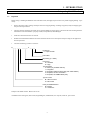
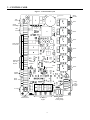
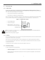
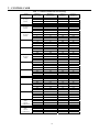

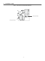
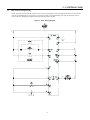


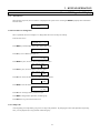
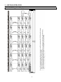

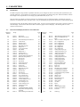
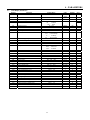


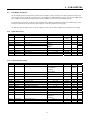
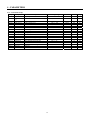
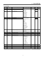
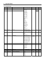


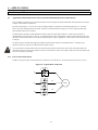


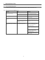

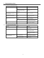

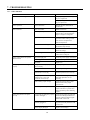

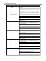
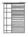
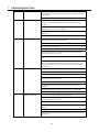
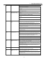


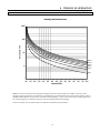
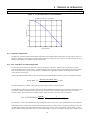

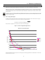


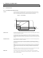

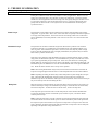


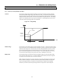
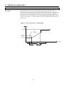
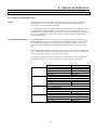
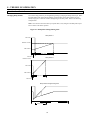
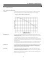
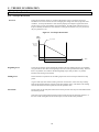
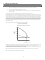
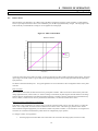
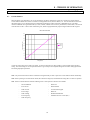
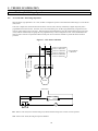
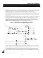


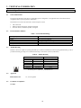


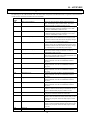
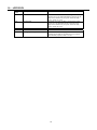
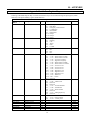


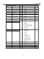
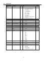
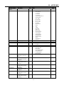
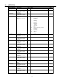
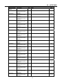
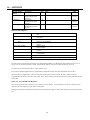

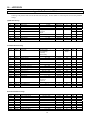
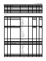
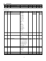
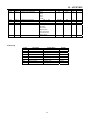


![MX2 sync [final].vp](http://vs1.manualzilla.com/store/data/005975841_1-4533d2555e3004ab9339335fb150c7a8-150x150.png)
![EX MV MX3 User Manual [May16].vp](http://vs1.manualzilla.com/store/data/005646159_1-0d378a1c318c2dc00419aef6af60da73-150x150.png)