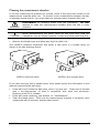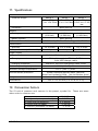
1
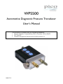
WPS500 Automotive Diagnostic Pressure Transducer User’s Manual This accessory complies with the following standards: Electromagnetic Compatibility (EMC) Directive 2004/108/EC FCC Part 15 Pressure Equipment Directive 97/23/EC Article 3.3 DO157-3 1. Safety terms and symbols Appearing in this manual: WARNING statements identify conditions or practices that could result in injury or death. WARNING CAUTION CAUTION statements identify conditions or practices that could result in damage to this product or other property. Appearing on the product: Danger of personal injury or property damage. manual for details. 2 Refer to DO157-3 2. General safety summary Please review the following safety precautions to avoid injury and prevent damage to this transducer or any equipment that is connected to it. DO connect safely This transducer must be connected using only the pressure hoses and connectors supplied. Pico Technology cannot accept responsibility for damage or injury caused by the use of unsuitable pressure hoses or connectors. DO follow the vehicle manufacturer’s safety instructions This is particularly important when connecting the transducer to pressurized fuel lines. DO ground the unit when working with fuels When working on or near fuel systems, you must connect the transducer to an electrical ground. If you are using the transducer with a PicoScope oscilloscope, connect a suitable lead from any unused BNC connector on the front panel of the scope to the ground of the vehicle. DO wear appropriate personal protective equipment Wear appropriate pressurized fluids. DO157-3 personal protective equipment (PPE) when working with 3 DO NOT exceed maximum working pressure To avoid injury, do not use the transducer with pressures above 500 psi / 34.5 bar. DO NOT exceed maximum temperature The lithium polymer (LiPo) battery inside the transducer can be damaged by excessive heating. Do not store or operate the unit at temperatures above 60 °C (140 °F). DO NOT operate without covers To avoid equipment damage and personal injury, do not operate this transducer with the covers removed. DO NOT operate in wet or damp conditions To avoid incorrect readings and possible equipment damage, do not operate this transducer in wet or damp conditions or submerge it in liquid. The transducer is splash-resistant but not immersion-proof. DO NOT operate in an explosive atmosphere To avoid personal injury and fire hazard, do not operate this transducer in an explosive atmosphere. DO NOT operate the transducer if damaged If you suspect there is damage to this transducer, have it inspected by qualified service personnel. Do not attempt to dismantle or repair it yourself. DO NOT use with damaged or modified pressure hoses All the pressure hoses supplied by Pico have been pressure-tested and must not be used if they have been disassembled, modified or damaged. 4 DO157-3 3. Description The WPS500 automotive diagnostic pressure transducer allows quick and accurate pressure analysis of many automotive systems. It can be used for many different pressure diagnostic applications, saving the need to own several transducers for several applications. It offers these features: high resolution and accuracy auto-zeroing built-in zoom tool integrated bleed-off / pressure relief valve three pressure ranges CAUTION DO157-3 The WPS500 is intended for immediate diagnostic purposes and not long-term or permanent use. For example, it should not be connected to a race car as a monitoring system. 5 4. Re-ordering codes If you need to reorder spare parts, please use the part numbers listed here. WPS500 pressure transducer Part No TA060 Qty 1 Description WPS500 pressure transducer WPS500X pressure transducer kit If you purchased the WPS500 pressure transducer as part of the WPS500X kit, you will have received the following items packaged with it: Part No TA081 TA082 TA083 TA084 TA085 TA086 TA087 TA088 DO157 MI220 6 Qty 1 1 1 1 1 1 1 1 1 1 Description USB to mini-USB charging cable 2 m (6-foot) BNC to BNC cable Fuel adaptor Extension hose Vacuum hose Bleed hose Exhaust adaptor M14 compression hose WPS500 manual Hard plastic carrying case DO157-3 5. The parts of your WPS500 pressure transducer Signal output to oscilloscope Front-panel controls USB charging port Bleed screw Signal output Front-panel controls USB charging port Inlet port Bleed vent Bleed screw DO157-3 Inlet port Bleed vent Use the BNC-to-BNC cable supplied to connect this to your oscilloscope. See Section 6. For battery recharging only (no data connection). Connect to any USB port on a computer or wall charger. Connect the pressure hose here. When the bleed screw is opened, this vent allows fluid to drain out of the measurement chamber. Turn counter-clockwise to open the bleed vent. Remember to close it before making the next measurement. 7 6. Front-panel controls Charging indicator Lights up when battery is charging. Low battery indicator Lights up when power is on but battery is low. Range indicators Show which of the three ranges is selected. Zoom indicators Show which of the three zoom modes, if any, is in use. Power button Press once to switch on. Press once again to switch off. Keep the unit switched off when not in use to conserve battery power. Battery fault indicator Lights up if there is a problem with the battery. Range button Press to cycle through the three ranges. Zoom button Press to cycle through the three zoom modes. Zoom mode subtracts the static pressure and magnifies the remaining dynamic pressure. See Section 7: “Operating modes” 8 DO157-3 7. Operating modes Ranges 1 to 3 Select the range using the Range button shown in Section 6: “Front-panel controls”. Range 1: The first range measures from -15 psi (-1 bar) to +500 psi (34.5 bar). It offers high resolution and accuracy for high-pressure tests such as cranking and running cylinder compression or fuel pressure testing. It is also helpful for identifying cam timing issues such as jumped timing belts and stretch timing chains, especially on multi-cam engines that may not have a cam sensor on each camshaft. The WPS500X kit includes a specially designed compression hose for performing this test with a significantly reduced error and higher operating temperature range than conventional compression hoses and adapters. Range 2: The second range measures from -15 psi (-1 bar) to +50 psi (+3.45 bar). This range is ideal for vacuum test and fuel system tests. When testing these systems the zoom function is especially useful to analyze valve operation with the vacuum waveform or the injectors through the fuel waveform. Range 3: The third range measures -5 to +5 psi (-0.345 to +0.345 bar). This setting is sensitive enough to analyze small pressures or pulses such as exhaust pulses from the tail pipe. Zoom modes 1 to 3 The zoom feature operates by removing all of the voltage from the signal below 100 Hz and then magnifying the remaining signal. Select the zoom using the zoom button shown in Section 6: “Front-panel controls”. Zoom 1: This mode multiplies the signal 10 times. Zoom 2: This mode multiplies the signal 100 times. For example, let’s say the transducer is connected to intake manifold vacuum on a running engine at idle with the transducer set to mode 2 (-15 to +50 psi or -1 to +3.45 bar) and the waveform on the scope is at -9 psi (-0.6 bar). The fluctuation in the signal caused by the valves’ opening and closing compared with atmospheric pressure forcing air into the manifold will be visible but will only make up a small portion of the overall signal. Selecting the zoom function will bring the waveform up to the zero line (remove the -9 psi portion) and the fluctuations will be magnified, making analysis of this component of the signal much clearer. Zoom 3: Zoom level 3 multiplies the signal by about 1,000 times. sensitive and is suitable only for vacuum measurements. DO157-3 It is extremely 9 8. Preparation for use Compatible fluid types The WPS500 is suitable for use with the following types of fluid: Brake, clutch and other hydraulic fluids Gasoline and diesel Air Water Before first use 10 Remove all packaging. Charge the internal battery. For instructions, see Section 10: “Maintenance”. DO157-3 9. Making a measurement Making a pressure measurement involves the following steps. explained in more detail in the sections below. Each step is Prepare the transducer Measure pressure Release the pressure in the measurement chamber Clean the measurement chamber Preparing the transducer Ensure that the transducer’s internal battery is charged. Unplug the charging cable from the transducer. Before switching on, disconnect any pressure source from the transducer. A pressure source left connected will interfere with the self-calibration procedure described below. Switch on the transducer and wait until the three Range LEDs light up in sequence. At the end of the sequence, Range 1 LED remains lit, showing that the transducer has finished its auto-zeroing procedure. The entire procedure should take less than 10 seconds. Measuring pressure Ensure that the bleed screw is firmly closed. Connect the appropriate pressure hose to the pressure sensing port. WARNING WARNING Use only the pressure hoses and connectors supplied with the WPS500. Pico Technology cannot accept responsibility for damage or injury caused by the use of unsuitable pressure hoses or connectors. Always check that the pressure hose is securely fastened to the transducer before pressurizing the system. Always check for leaks when connecting the unit and to never leave it connected to a vehicle unattended (especially when connected to fuel). If measuring liquid pressure, bleed any air out of the measurement chamber first. Use the BNC cable supplied to connect the output of the transducer to the input channel of the oscilloscope. Switch on the computer and run the PicoScope software. In the PicoScope software, select the “Automotive” menu and then the appropriate pressure test. Press the Range button on the transducer to select the desired measuring range. Start the vehicle’s engine. A waveform showing the pressure of the system will appear on the PicoScope display. DO157-3 11 Releasing the pressure in the measurement chamber After each measurement, some fluid will remain under pressure in measurement chamber. Follow the instructions below to release the pressure. Hold the transducer over a suitable container to catch the fluid expelled from the bleed vent. WARNING 12 the The fluid released from the bleed vent may be under high pressure. Position the transducer so that the fluid released cannot cause damage or injury. SLOWLY loosen the bleed screw by turning it counter-clockwise. remove the screw from the transducer. Allow the fluid to emerge from the bleed vent. When no more fluid emerges, tighten the bleed screw. Do not DO157-3 Cleaning the measurement chamber If you are measuring the pressure of a liquid, some of the liquid will remain in the measurement chamber after use. To prevent cross-contamination between liquids, or between liquids and air, you must clean the measurement chamber after use. WARNING DISCONNECT all pressure hoses from the transducer. DO NOT attempt to clean the measurement chamber when the unit is under pressure. CAUTION When disassembling the bleed valve for the first time, hold the transducer over an empty container in case any loose parts drop out. Remove the bleed screw and allow any liquid to drain out. Your WPS500 pressure transducer has either a ball valve or a needle valve, as shown in the two drawings below. WPS500 with ball valve WPS500 with needle valve If you have the type with a needle valve, then please ignore the information in this manual concerning the ball valve. If the ball is still inside the ball valve, allow it to drop out. Clean and oil the ball with a non-hygroscopic oil that is compatible with steel and aluminum. Ordinary motor oil is suitable. If the ball needs replacing, see Section 10: “Maintenance”. Clean the bleed screw. Flush out the measurement chamber if necessary, then replace the ball (if present) and the bleed screw. DO157-3 13 10. Maintenance Cleaning the housing Clean the transducer’s housing by wiping it with a rag moistened with clean water or water-based detergent. Allow the housing to dry before use. Do Do Do Do Do not not not not not use fuel or any other solvent use abrasive cleaning agents submerge the unit in any liquid dismantle the unit use the unit until it is perfectly dry. Recharging the internal battery To charge using a computer, switch on the computer and allow it to boot. Disable any power-saving modes to ensure that the computer does not switch off before recharging is complete. Connect the transducer to the USB port of the computer using the USB charging cable provided. To charge using a USB wall charger, connect the transducer to the charger using the USB charging cable provided. Leave the transducer to charge for 5 hours. Unplug the USB cable from the transducer before use. Leaving the cable plugged in may affect measurement accuracy. Repairs If the unit is damaged or stops working, return it to Pico Technology or an authorized Pico distributor for repair. Do not attempt to dismantle or repair the unit. Replacing the bleed valve ball If the ball in the bleed valve is lost, it can be replaced with a standard 0.25 inch (6.35 mm) steel bearing ball. To re-seat the ball, clean the port and then seat the ball using a brass drift. Disposal The WPS500 contains a lithium polymer (LiPo) battery. When the transducer reaches the end of its life, take the entire unit to a battery recycling facility. YOU MUST observe the instructions below. battery could cause a fire or an explosion. Incorrect disposal of the WARNING 14 Do not open the unit to remove the battery Do not crush or shred the unit Do not dispose of in fire DO157-3 11. Specifications Inlet Pressure ranges Range 1 Range 2 Range 3 -5 to +5 psi -15 to +500 psi -15 to +50 psi -1 to +34.5 bar -1 to +3.45 bar -0.345 to +0.345 bar Connector Male push-fit Output Scaling 1 V/100 psi (6.89 bar) Offset (typical) 1 V/10 psi (0.689 bar) 1 V/1 psi (0.0689 bar) Auto-zeroing Connector BNC female, fits Pico Technology cable TA082 Performance Accuracy Response time (10% to 90%) 1% of scale 1% of scale 5% of scale 100 µs 100 µs filtered Power supply Type Built-in LiPo battery, not user-serviceable Charging current Charging connector 500 mA (max.) at 4.75 V to 5.25 V from USB charger cable USB mini, fits Pico Technology cable TA081 Ambient operating temperature 60 °C (140 °F) max. Ambient storage temperature 60 °C (140 °F) max. Environmental protection Splash-resistant against water, gasoline, diesel and hydraulic fluids. Not immersion-proof. Weight 332 g (11.7 oz) Dimensions 133 x 74 x 30 mm (5.2 x 2.9 x 1.2 in) 12. Conversion factors The SI unit of pressure and vacuum is the pascal, symbol Pa. other units in common use: 1 1 1 1 1 DO157-3 bar psi (pound per square inch) inHg (inch of mercury) inH2O (inch of water) mmH2O (millimeter of water) 100 000 ≈ 6 895 ≈ 3 386 ≈ 250 ≈ 10 These are some Pa Pa Pa Pa Pa 15 Issue history: 1. 2. 3. 1.6.09 14.7.09 21.9.09 First issue. Corrections to power LED description, etc. Added FCC statement, needle-valve version. Pico Technology James House Colmworth Business Park St. Neots PE19 8YP United Kingdom www.picoauto.com This device complies with part 15 of the FCC Rules. Operation is subject to the following two conditions: (1) This device may not cause harmful interference, and (2) this device must accept any interference received, including interference that may cause undesired operation. Pico Technology is a registered trademark of Pico Technology Ltd. Manufactured in the United States Copyright © Pico Technology Ltd. 2009 16 DO157-3