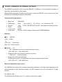
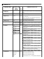
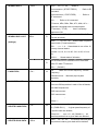
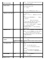
1
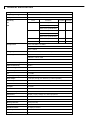
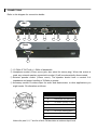
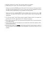
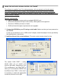
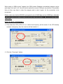
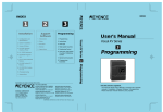
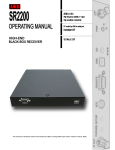
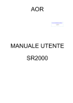
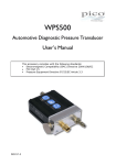
Safety notices
Every effort has been made to make this manual correct and up to date. Due to continuous
development of the product and by error or omission, anomalies may be found and this is
acknowledged.
© This manual is protected by copyright AOR Ltd 2013. No information contained in this manual
may be copied or transferred by any means without the prior written consent of AOR Ltd. AOR
and the AOR logo are trade-marks of AOR Ltd. All other trade marks and names are
acknowledged. E&OE
Level of risk
As the SR2200 is powered from 12V DC, there is little chance of serious injury as long as
common sense is applied.
DC input is a nominal 12V DC wired center positive. Reverse polarity connection will damage the
SR2200 and potentially could lead to the risk of fire or explosion under severe circumstances.
NEVER connect the SR2200 directly to an AC outlet.
Handling the SR2200
Use a soft, dry cloth to gently wipe the SR2200 clean, never use abrasive cleaners or organic
solvents which may damage certain parts. Treat the unit with care, avoid spillage or leakage of
liquids into the cabinet. Special care should be taken to avoid liquid entering via the connection
sockets.
Special remarks
Do not use or leave the SR2200 in direct sunlight. It is best to avoid locations where excessive
heat, humidity, dust and vibration are expected. Always keep the SR2200 free from dust and
moisture.
Other warnings
There are no internal operator adjustments. In the unlikely event of servicing being required,
please contact your dealer for technical assistance.
Although carefully designed, the SR2200 (like all receivers) suffers from a degree of internal
noises known as spurii. They are a product of the receiver circuitry and do not represent a fault.
The reception might be affected by interferences produced by nearby electrical appliances such
as television, PC, walkie-talkies, etc... The reception might be strongly affected by powerful
transmissions if the receiver or the antenna is located nearby a transmitter (such as TV
broadcasting transmitter).
Transmissions with encrypted content cannot be decoded by this receiver.
Specification is typical but not guaranteed, subject to change without notice due to continuous
development of the product.
TECHNICAL SPECIFICATIONS
Configuration
Triple conversion superheterodyne
Frequency coverage
25MHz - 3GHz
Reception modes
AM / NFM / WFM / SFM
Band
Sensitivity
IP3 (dBm)
S/N (dB)
25M-225MHz
NFM: 0.35uV (12dB SINAD)
1
40
1
35
Sensitivity
IP3
S/N
AM: 0.6uV (10dB S/N)
WFM: 2.0uV (12dB SINAD)
225M-1.7GHz
NFM: 0.35uV (12dB SINAD)
AM: 0.8uV (10dB S/N)
WFM: 2.0uV (12dB SINAD)
IF frequencies
1.7GHz -2.7GHz
NFM: 0.6uV (12dB SINAD)
1
32
2.7GHz-3GHz
NFM: 1.5uV (12dB SINAD)
1
30
1st IF: 255.3MHz, 744.3MHz
2nd IF: 10.7MHz
3rd IF: 455kHz
Tuning steps
100 Hz to 100 kHz (10 Hz incremental)
Selectivity
NFM: +/-10kHz, 60dB
AM/SFM: +/-6kHz, 60dB
WFM: +/-180KHz, 60dB
Spurious Sensitivity
60dB>
Adjacent Selectivity
55dB >
Dynamic Range
90dB>
Unwanted Spurious emissions
< -57dBm
IP3
+1.0 dBm
Frequency stability
+/-1ppm (0-50℃)
Audio output
1.2W (8Ω) max.@ 10% distortion (no internal speaker!)
Power requirements
12 - 16V DC, 0.5 A with 1W audio output
Aerial connection
50Ω BNC
IF output
10.7MHz
Control interface
RS-232C / USB , 38400bps
Operation temperature
0 to 50℃
Dimensions
200(W) x 31(H) x 230(D) mm, without projections
Weight
1.23kg
Nominal filter bandwidths
6kHz, 15kHz, 300kHz.
Memory channels
1000 (10 banks)
Search banks
40
Scan/Search Rate
25 steps per second.
Pass frequencies
2000
Priority channels
1
SUPPLIED ACCESSORIES
•
DC power cable
•
Operating manual
•
Basic control software for testing purposes, on CD. This software does not support USB
connections, only RS-232C. If your PC (particularly laptops) does not feature a RS232C
port, you may alternatively use a “USB to SERIAL” adapter. This software is supplied “as
is” without any guarantee of any kind.
•
•
Complete command list (inside the manual)
USB driver on CD.
CONNECTIONS
Refer to this diagram for connection details:
BAC
1
2
3
4
5
6
7
8
9
FRON
T
10
① 10.7MHz IF OUT with +/- 5MHz of bandwidth.
② Headphone socket (3.5mm mono jack, also wired for stereo plug). When this socket is
used, any external speaker connected to socket (3) will be automatically disconnected.
③ External speaker socket (3.5mm mono). The speaker should have a nominal 8 Ω
impedance and power handling of 2 Watts or greater.
④ Accessory socket. Provides output for audio and discriminator, or other applications you
might create. Pin allocation as follows:
PIN NUMBER
CONNECTION
1
6V DC @ 30mA max.
2
Discriminator out, 500mVp-p
3
10.7MHz IF (no amp, no filter)
4
No connection
5
No connection
6
AF out (H), 120mV @ 600Ω
7
AF out (L), 60mV @ 600Ω
8
Ground
Values for pins 2, 6, 7 are for a 3kHz FM deviation at antenna input level.
⑤ RS-232C socket for PC control. The connection cable is not supplied..
⑥ USB socket for PC control. The connection cable is not supplied.
When you connect the SR2200 (power ON) to the PC for the first time, Windows will detect
the USB connection and ask you for a driver. At this time insert the supplied CD and find
the folder named “USB DRIVER”. Driver installation will be automatic.
Please note that the supplied SR2200 control software does not function with a USB
connection. You may use the Windows “Hyper Terminal” software which is supporting USB
connections.
⑦ 12V DC input socket. The DC power cable is supplied. Please connect it to a power unit
providing 12 to 16V DC, with minimum 0.5 A. Center pin is positive.
⑧ Power switch and power LED. Unit is powered and the green LED is lit, when the switch is
in the upper position.
⑨ Antenna socket. BNC type. Preferably use an antenna with coaxial lead matched to 50Ω,
for optimal performance.
⑩ Remote control panel. The optional control panel head (with internal speaker), similar to
the control panel of AR-ONE is used to test functionality of the receiver, when a PC is not
available.
CONTROL COMMANDS FOR TERMINAL SOFTWARE
The SR2200 is operated via PC using the RS232C, or USB port. The commands necessary to
that effect, are described in this chapter.
Microsoft Windows Hyper Terminal may be used to control the SR2200, or you may use your own
software by integrating the following commands.
Communication parameters
•
•
•
•
Baud rate
Data length
Stop bit
Parity
38400 BPS
8 bits
- ^A nn [cr],[LF] O ^A = 13 Hex O nn = Receiver's ID #
1 bits
If ID # = 00 (DEFAULT VALUE), command can be input directly.
NONE
•
•
Flow control
Local echo
NONE
ON (set in ASCII settings of Microsoft HYPERTERMINAL)
Delimiter
■PC → SR2200
<CR> (0x0d)
or
<CR><LF> (0x0d 0x0a)
Note: <LF> will be ignored
■SR2200 → PC
• “OK”response when the command has been correct:
<SP><CR><LF>(0x20 0x0d 0x0a)
•
Response when the command has been incorrect:
?<CR><LF> (0x3f 0x0d 0x0a)
•
Response to the read command:
Following the output of the parameter, the correct response should read:
<SP><CR><LF>(0x20 0x0d 0x0a)
Numerical parameter auto-correct
The SR2200 does correct the numerical command parameter to the digit format applying to the
given parameter. In the following example, the DB command has to be followed by a 3-digit
number.
Ex.: DB003 <CR>
The SR2200 will add one or two “0” in order to achieve three digits.
DB3<CR> ......... processed as DB003<CR>
DB03<CR> ....... processed as DB003<CR>
However be aware that for some commands like Memory Channel or Search Bank, if you input
MQ33 for MQ303 (bank 3, channel 3), the SR2000 would mistakenly correct your entry to MQ033
which means bank 0, channel 33.
COMMAND LIST
COMMAND NAME
REQUEST CMD
CMD or
HEADER
COMMAND DESCRIPTION
R/W
- POWER ON
x
W
- POWER OFF
QP
W
- REMOTE ON
^Ann
W
When the receiver's power is off, any key will power
it on.
POWER-OFF the receiver
^Ann O nn = ID # O means control unit A with
ID # = 00 to 99
(Note)In case ID # = 00 ( DEFAULT VALUE ),the
command can be input directly.
- REMOTE OFF
EX
W
Stop control of remote receiver
- ID ( REMOTE )
IDnn
W
nn = 00 - 99 (Setting an ID to the remote receiver )
R
IDnn
W
VFO selection. x = A - J ( DEFAULT is VFO-A )
- Rx-MODE
Vx O
Memory Read. m = BANK # from 0 - 9 and n = CH #
MRmnn
from 00 - 99.
MSm
Memory Scan. m = BANK # from 0 - 9
SM
Memory Select
SSmm
Normal Search. mm = BANK # from 01 - 40
RX
R
RFU STATUS
MR MXmnn RFnnnnnnnnnn STnnnnnn AUn MDn
BWn ATn AMn TMxxxxxxxx
MS MXmnn RFnnnnnnnnnn STnnnnnn AUn MDn
BWn ATn AMn TMxxxxxxxx
SM MXmnn RFnnnnnnnnnn STnnnnnn AUn MDn
BWn ATn AMn TMxxxxxxxx
SSmm RFnnnnnnnnnn STnnnnnn AUn MDn BWn
ATn AMn TTxxxxxxxx
Vx RFnnnnnnnnnn STnnnnnn AUn MDn BWn ATn
AMn
(Priority Channel) PPmnn RFnnnnnnnnnn
STnnnnnn AUn MDn BWn ATn AMn TMxxxxxxxx
- FREQUENCY
RFnnnnnnnnnn
W
Active VFO's Frequency in Hz.
RFnn.nn
Active VFO's Frequency in MHz
RFnnn
Active VFO's Frequency in MHz
Vx O
Vx nnnnnnnnnn ( Hz ) VFO selection followed by
frequency in Hz.
- FREQ STEP
- RECEPTION MODE
RF
R
STnnnnnn
W
Active VFO's Frequency. RFnnnnnnnnnn ( Hz )
Frequency STEP in Hz. Not valid for Search.
(AUTO MODE will be set to off)
STnn.nn
Frequency STEP in KHz.
STnn
Frequency STEP in KHz.
ST
R
Frequency STEP in Hz. STnnnnnn ( Hz )
MDn
W
n = 0 O NFM
( BW = 15 K )
n = 1 O WFM
( BW = 300 K )
n = 2 O AM
( BW = 6 K )
n = 3 O SFM ( BW = 6 K )
n = 4 O WAM ( BW = 15 K )
- AGC
MD
R
MDn
AC n
W
n = 0 O AGC-OFF
n = 1 O AGC-FAST
n = 2 O AGC-SLOW
n = 3 O AGC-MIDDLE
- RF-ATTENUATOR
AC
R
ACn
ATn
W
n = 0 O 00 dB
n = 1 O 10 dB
n = 2 O 20 dB
n = 3 O AUTO (Depending on the signal level,
RF-AMP will automatically change to on or off)
- RF-AMP
AT
R
ATn ( n = 3 O AUTO ATT/AMP )
AMn
W
n = 0 O RF-AMP OFF
n = 1 O RF-AMP ON
n = 2 O AUTO (Depending on the signal level, ATT
will automatically change to on or off)
- NOISE-SQUELCH
RQnnn
R
Amn ( n = 3 O AUTO ATT/AMP )
W
RQnnn O nnn = 000 - 255
This command can be applied to VFO, MEMORY
THRESHOLD
and SEARCH DATA
When the optional Remote Control Panel is
connected, the AF-volume must be turned to
minimum for the command to function.
RQ
R
RQ nnn
- LEVEL-SQUELCH
DBnnn
W
DBnnn O nnn = 000 - 255 (Default is 000 for off)
This command can be applied to VFO, MEMORY
THRESHOLD
and SEARCH DATA
When the optional Remote Control Panel is
connected, the AF-volume must be turned to
minimum for the command to function.
- AF-GAIN
DB
R
DB nnn
AGnnn
W
AGnnn O nnn = 000 - 255 (Default is 255)
When the optional Remote Control Panel is
connected, the AF-volume must be turned to
minimum for the command to function.
- MANUAL-GAIN
AG
R
AG nnn
MGnnn
W
MGnnn O nnn = 000 - 255 (Default is 255)
AGC must be set to OFF.
- SELECT SQUELCH
MG
R
MG nnn
SQn
W
n = 0 O NOISE-SQ (DEFAULT)
n = 1 O LEVEL-SQ
- SIGNAL-LEVEL
SQ
R
LM
R
SQn
ATn AMn NSQm LMnnn O When NOISE-SQ is
selected ( nnn = 000 - 999 )
ATn AMn LSQm LMnnn O When LEVEL-SQ is
selected ( nnn = 000 - 999 )
m = 0 O SQUELCH closed
m = 1 O SQUELCH open
- AUTO SIGNAL
LCn
W
n = 0 O OFF
n = 1 O ON ( When the squelch opens, signal
LEVEL
level and frequency are returned )
LC
R
LCn
R
SQm LCnnn RFnnnnnnnnnn
m = 0 O When NOISE-SQ is selected.
- SCAN/SEARCH
SGn
W
When scan/search is in operation: when it stops,
the squelch opens and closes again. Then
scan/search resumes . This SG command repeats
RE-START CMD
the process.
n = 0 O NO-OPERATION
n = 1 O Re-starts [SG]
SG
R
SGn
- DELAY-TIME
DDO
W
DD n.n O n.n = 0.0 - 9.9 sec ( DEFAULT = 2.0
sec )
Delay before shifting to next channel.
nn = FF O HOLD
- FREE SCAN
DD
R
SPO
W
DDn.n or DDFF
SPnn O n.n = 0.0 - 9.9 sec (decimal can be
omitted)
n.n = 0.0 O FREE-SCAN OFF ( DEFAULT )
= 0.1 - 9.9 sec
- SELECT S-METER
SP
R
SPn.n
SFO
W
n = 0 O DIGTAL METER O dBuV ( DEFAULT )
n = 1 O DIGTAL METER O dBm
- DUPLEX ON/OFF
OFnnx
R
SFn
W
OFnnx O nn = 00 - 47 ( 00 = OFF )
O x = + or -
- DUPLEX FREQ
OF
R
OF xnn
OLmm nnnOn
W
OLmm nnnnnnnn00 O mm = 01 - 19
O nnnnO n = FREQ-DATA ( up to 1000 MHz, 100
SETTING
Hz step )
OLmm
- INTERVAL TIME
R
OLmm nnnnnnnnnn
OL
OLmm nnnnnnnnnn
ABnn
ABnn O nn = 02 - F0
nn = 02 O APPROX 100 ms
OF AUTO ATT/AMP
nn = 03 O
150
nn = 08 O
350
nn = 0B O
500 ( DEFAULT )
nn = 10 O
700
nn = 30 O
2000
nn = F0 O
AB
- S-METER LEVEL
LU
ABnn
R
LU nnn O -nn ~ nnn
( dBuV )
- S-METER LEVEL
LB
R
(constant)
LB O S-METER LEVEL ( dBm )
LB nnn O -nnn ~ nnn
( dBm )
- S-METER GAIN
LU O S-METER LEVEL ( dBuV )
KKnn
W
KKnn O nn = 00 - 99 ( 1.00 - 1.99 )
KK
R
KK nn
- SEARCH DATA
SEnn O
W
SEnn O nn = 01 - 40 O BANK #
SLnnnnnnnnnn ( START-FREQ )
O Refer to RF
command
SUnnnnnnnnnn ( STOP-FREQ )
O Refer to
RF command
AUn OO Refer to AU command
STnnnnnn, MDn, BWn, ENn, ATn, AMn, AC n O
Separate commands with one blank space.
TTxxxxxxxx ( TITLE ) O Use if necessary.
Spaces are OK.
- SEARCH DATA LIST
SRnn
R
SR
O CURRENT BANK'S SEARCH-DATA
(Format as below)
SRnn O nn = 01 - 40 O Search data of specific
(settings)
search bank (Format as below)
SRn OO n = 1 - 4 O Search data in one of the 10
memory channel banks.
(1=bank 1 to 10, 2=11 to 20, 3=21 to 30, 4=31 to
40)
SR%% O Search data of all banks
R
SRn SLnnnnnnnnnn SUnnnnnnnnnn AUn MDn
BWn ATn AMn TTxxxxxxxx
SRn --- ( BLANK )
- PASS-FREQ
PWO
W
PW OO Make the current frequency, a PASS
Frequency.
PWnnnnnnnnnn O Manually input a pass
frequency.
- PASS-FREQ LIST
PRO
R
PRnn O nn = 01 - 40 ( BANK # )
There are 50 frequencies in each of the 40 banks,
total 2000 frequencies.
PR00 nnnnnnnnnn
PR01 nnnnnnnnnn
:
:
PRmm --- DELETE PASS-FREQ
PDO
W
PDmmnn O mm = 01 - 40 ( BANK # ) / nn = 00 49 ( PASS-CH # )
O A given pass frequency of
a specific bank are deleted,
PDmm%% O mm = 01 - 40 ( BANK # ) O All
pass frequencies from a given bank are deleted.
- DELETE SRCH DATA
QSnn
W
QSnn O nn = 01 - 40 O The search data and pass
frequencies inside a given bank will be deleted.
QS%% O The search data and pass frequencies of
WITH PASS-FREQ
- COPY TO VFO
ALL banks will be deleted.
SVO
W
SVn O n = 0 - 9 ( VFO-A - VFO-J ) O Copy the
current search data to VFO.
n = 0 O VFO-A
:
:
n = 9 O VFO-J ( DEFAULT 時、 VFO-J へ )
- MEM DATA SETTINGS
MX O
W
MXmnn O Write CURRENT RX-DATA to BANK #
= m, CH # = nn
MXmnn O m = 0 - 9 O BANK # / nn = 00 - 99 O
CH #
RFnnnnnnnnnn ( FREQUENCY )
O Refer to
RF command.
AUn OOOOO Refer to AU command.
STnnnnnn, MDn, BWn, ENn, ATn, AMn, AC n O
Separate each command with a space.
GAn O ( GA O M-SEL ON/OFF ) O Separate
each command with a space.
TMxxxxxxxx ( TITLE ) O Use if necessary.
Spaces are OK.
- MEM DATA LIST
MAO
R
MAm O m = 0 - 9 ( BANK # ) (Format as below)
MAmnn O m = 0 - 9 (BANK # ) / nn = 00 - 99 ( CH
# ) O Only for the specified memory channel.
MXmnn MPn Gan RFnnnnnnnnnn AUn MDn BWn
ATn AMn TMxxxxxxxx
MXmnn ---
- MEMORY SELECT
GAO
W
ON/OFF
- SEL MEM LISTING
GA
R
GRO
R
n=
0 O OFF
n=
1 O ON
GAn
GRnn O nn = 00 - 99 ( Display of specified memory
channel )
GR%% O ALL-CH ( MAX 100-CH )
GRn O n = 0 - 9 ( 10 channels are set and
displayed )
GR O
List up content of all 10 channels
GRnn mxx O nn = CH # / m = MEM-BANK # / xx =
MEM-CH #
- DELETE MEM
MQn
W
MQn O n = 0 - 9 ( BANK # )
MQ%% O ALL-BANK
- MOVE TO VFO
MVO
W
MVn O n = 0 - 9 ( VFO-A - VFO-J ) O Apply the
current memory data to VFO.
n = 0 O VFO-A
:
:
n = 8 O VFO-I ( DEFAULT )
n = 9 O VFO-J
- MEM-CH READ
MRmnn
W
MR O READ CURRENT MEMORY DATA
MRmnn O m = 0 - 9 O BANK # / nn = 00 - 99 O
CH #
MW O To save the data of the frequency currently
- MEMO WRITE
MW
W
being received. Automatic memory channel
allocation.
- MEMORY BLANK
MBO
R
MBm O m = 0 - 9 ( BANK # )
Searches for available channels in a bank.
Channels are displayed by groups of 10, delimited
CHANNEL LIST
by [---].
example: 002 005 028 034 044 O 078 --PPmnn
W
PP
R
- INTERVAL TIME
TInn
W
OF PRIORITY
TI
R
- PRIO ON/OFF
PQn
W
- SELECT PRIO-CH
PPmnn O m = 0 - 9 O BANK # / nn = 00 - 99 O
CH #
PPmnn RFnnnnnnnnnn ( NORMAL ) or RF--( BLANK )
TInn O nn = 01 - 20 sec ( DEFAULT = 05 sec )
TInn
PQn O n = 0 or 1
n = 0 O OFF PRIORITY OPERATION
n = 1 O ON PRIORITY OPERATION
- LEVEL WAIT
PQ
R
PQn O n = 0 or 1
LTnn
W
LTnn O nn = 01 - 95
- Time during which the level is put on hold until it
stabilizes.
n = 1 O APPROX 1 ms
- DISPLAY FLASH
LTnn
R
DMnnnn
R
LTnn
DMmmmm O mmmm = 0000 - FFFF ( ROM
ADDRESS ) OLast of 4 digits must be "F".
DMmmmF:nn nn OO nn O 16 bytes per line, 8
MEMORY
lines.
(Space command allows view of following ROM
address )
- EDIT FLASH-
CM [SPACE ]
W
CMmmmm O mmmm = 0000 - FFFF
( ROM-ADDRESS )
mmmF:nn nn OO nn (To display the original 16
MEMORY DATA
byte data)
mmmF:
xx xx
(enter data instead of xx,
separate with blank space )
CMA00F 5A C3 O O
5A C3 ==>Changed to
00 00, Flash memory is initialized with [RESET] or
[PWR-ON].
- MODIFY FLASH
MMO
W
LWO
W
MMmmmF nn nn nn nn O nn (At the address
mmmF, 16-BYTE DATA is input)
MEMORY
- PLL UNLOCK
(Time setting for PLL lock after frequency change.
WAIT-TIME
- SQ WAIT-TIME
LWnn O nn = 02 - 20 ms ( DEFAULT = 02 )
Wrong timing might create PLL errors.)
LW
R
LWnn
SWO
W
SWnn O nn = 00 - 50 ms ( DEFAULT = 10 )
Signal squelch check time after the PLL is locked.
- BIRDIE CANCELL
SW
R
PLn
W
SWnn
Shifting the PLL data from the current reception
frequency.
n = 0 O OFF
REQUEST
n = 1 O +200K
n = 2 O -200K
- MAIN VERSION #
PL
R
PLn
VR
R
VR O MAIN VERSION #
VR yyyy-mm-dd
- VFO DEFAULT
CL [cr]
W
- RESET
RS [cr]
W
CL OReset the VFO to default.
Flash ROM is re-initialized, after switching the
receiver off and on again.
( SRCH-DATA and MEM-DATA will be lost! )
- SERIAL #
SNnnnnnnnnnn
W
SN [cr]
R
SNnnnnnnnnnn O nnnnnnnnnn O SERIAL # ( 10
digits )
SNnnnnnnnnnn
USING THE SUPPLIED “SR2200 CONTROL SOFTWARE””
The software is supplied "as is" for testing purposes, with no warranty nor formal support.
The “SR2200 CONTROL SOFTWARE” only recognizes the receiver’s RS232C connector.
If your PC (particularly laptops) does not feature a RS232C port, you may alternatively use a
“USB to SERIAL” adapter.
System requirements:
•
IBM PC compatible receiver with an available RS232C port.
•
•
•
Microsoft® Windows® 98 up to Vista (32 bit). 64bit systems not supported.
Pentium® 300MHz processor or faster
RAM and hard disk space requirements are negligible.
① Connect the SR2200 to your PC using a serial cable. Make sure that you have powered on
the SR2200.
In case you would like to use a “USB to serial” adapter, install this adapter first as specified by
the manufacturer’s instructions.
② Install and launch the control software. The main control window looks like this:
The default COM PORT 1 setting
should allow you to control your
receiver right away. Depending on you
PC’s configuration, the COM PORT to
which you connected the SR2200 can
be different from COM1. In this case it
is necessary to select the appropriate
number as pictured on the right.
When using a “USB to serial” adapter, the COM number Windows automatically assigns can be
quite high, such as 5 to 8. You will need to select the correct COM port, as pictured. It is possible
that you then may have to close the program and to start it again, for the connection to be
recognized.
Please make sure that the RS232C port speed is set at 38400 bps and not 19200 bps, otherwise
the connection with the PC will fail. Access this option by selecting COM > Speed and then select
“38400 bps”.
HOW TO INPUT A FREQUENCY
① First select the VFO (VFO A to J) in which the frequency will be stored. If the VFO already
contains a frequency, then the receiver will be tuned to it.
② Click the “Freq.Input” button:
The following window will appear:
③ Input the desired frequency in the left frame and click OK. If other frequencies have been
stored previously in other VFO’s, you may select one in the right window, transfer it to the left
window by clicking on the <= arrow, and validate with OK.
OTHER FUNCTIONS
1
2
3
4
9
5
8
7
6
① Reception Modes: You have to manually choose between:
AM (Amplitude Modulation). IF filter bandwidth of 6 kHz.
NFM (Narrow Band Frequency Modulation): IF filter bandwidth of 15kHz.
WFM (Wide Band Frequency Modulation): IF filter bandwidth of 15kHz.
SFM (Super Narrow Frequency Modulation): IF filter bandwidth of 6kHz.
② Frequency Step size: You have to manually choose between 0.1, 0.5, 1, 2, 5, 6.25, 9, 10,
12.5, 20, 25, 30, 50, and 100kHz.
③ RF Preamplifier: Select either “auto”, “ON” or no selection for disabling the preamplifier.
④ RF Attenuator: Select either “auto”, “0dB”, “10”dB, or “20dB” of attenuation.
⑤ Signal Strength Meter: It is for relative signal strength comparison and calibration may not be
totally reliable.
⑥ Squelch Control: There are 2 types supported, NOISE squelch and (signal) LEVEL squelch.
Move the slide to the right (for values from 0 to 255) until the unwanted noise disappears.
⑦ Manual Frequency Tuning: Using the left arrow (for tuning down) or the right arrow (for
tuning up) you can decrease or increase the frequency by the value defined in the (2)
Frequency Step section. For finer tuning, use lower STEP values.
⑧ Volume Control: Represents the AF audio output through the external speaker &
headphones sockets. The SR2200 has no internal speaker!
Volume scale is from 000 to 255. Beware of excessive volume level when using headphones.
⑨ Functions not supported.
TERMINAL-THE COMMAND WINDOW
Access the Terminal window through
the VIEW menu.
This window allows you to monitor the
data flow from SR2200 to the PC, and
to check upon the SR2200 data
response when a Command Instruction
has been entered.
.
Memo
AOR, LTD.
2-6-4, Misuji, Taito-Ku
Tokyo, 111-0055, Japan
URL: www.aorja.com
US distributor:
AOR USA, INC.
20655 S. Western Ave. Suite 112
Torrance, CA 90501
Phone: 310-787-8615
Fax: 310-787-8619
URL: www.aorusa.com
e-mail: [email protected]
Dec.26, 2013
Printed in Japan