1
EPICS and CAEN x527 Series High Voltage
Power Supplies at the CLS
Version 1.2
DRAFT
2007-02-13
Contents
1 General Description
1.1 Overview . . . . . . . . . . . . . . . . . . . . . . . . . . .
1.1.1 CAEN x527 High Voltage Power Supply Hardware
1.1.2 CAEN HV Wrapper Software . . . . . . . . . . . .
1.2 CLS EPICS Implementation . . . . . . . . . . . . . . . . .
.
.
.
.
.
.
.
.
3
3
3
4
5
2 Use of Epics Software
2.1 Basic Graphical User Interface . . . . .
2.2 EPICS Database Records . . . . . . .
2.2.1 Process Variables for Users . . .
2.2.2 Description of Process Variables
2.3 Starting the IOC Application . . . . .
.
.
.
.
.
.
.
.
.
.
.
.
.
.
.
.
.
.
.
.
.
.
.
.
.
.
.
.
.
.
.
.
.
.
.
.
.
.
.
.
.
.
.
.
.
.
.
.
.
.
.
.
.
.
.
.
.
.
.
.
.
.
.
.
.
6
6
9
11
12
16
3 Programming Notes
3.1 Files . . . . . . . . .
3.2 CAEN HVWrapper .
3.3 Installation . . . . .
3.3.1 Requirements
3.3.2 Building . . .
3.3.3 Install . . . .
.
.
.
.
.
.
.
.
.
.
.
.
.
.
.
.
.
.
.
.
.
.
.
.
.
.
.
.
.
.
.
.
.
.
.
.
.
.
.
.
.
.
.
.
.
.
.
.
.
.
.
.
.
.
.
.
.
.
.
.
.
.
.
.
.
.
.
.
.
.
.
.
.
.
.
.
.
.
17
17
18
19
19
19
21
.
.
.
.
.
.
.
.
.
.
.
.
.
.
.
.
.
.
.
.
.
.
.
.
.
.
.
.
.
.
1
.
.
.
.
.
.
.
.
.
.
.
.
.
.
.
.
.
.
.
.
.
.
.
.
.
.
.
.
.
.
CONTENTS
3.4
3.5
3.6
CONTENTS
EPICS Driver . . . . . . . . . . . . . .
3.4.1 Syntax of Routines . . . . . . .
3.4.2 Description of Routines . . . . .
EPICS Driver Support Routines . . . .
3.5.1 Syntax of Routines . . . . . . .
3.5.2 Description of Routines . . . . .
3.5.3 Driver Support Entry Table . .
3.5.4 Database Definition Syntax . .
EPICS Device Support Routines . . . .
3.6.1 Syntax of Routines . . . . . . .
3.6.2 Description of Routines . . . . .
3.6.3 Device Support Entry Table . .
3.6.4 Database Definition Syntax . .
3.6.5 Required Database Field Syntax
.
.
.
.
.
.
.
.
.
.
.
.
.
.
.
.
.
.
.
.
.
.
.
.
.
.
.
.
.
.
.
.
.
.
.
.
.
.
.
.
.
.
.
.
.
.
.
.
.
.
.
.
.
.
.
.
4 To Do
4.1 Driver . . . . . . . . . . . . . . . . . . . . . .
4.1.1 Conversion to True EPICS Driver . . .
4.1.2 Scan Period Recoding . . . . . . . . .
4.1.3 Scan period debugging . . . . . . . . .
4.1.4 Writes Triggering Reads . . . . . . . .
4.1.5 Setting Scan Periods . . . . . . . . . .
4.1.6 Other Communication Methods . . . .
4.2 EPICS Record Alarms . . . . . . . . . . . . .
4.3 Parsing the Device Address in Device Support
4.4 Board and Crate Parameter Support . . . . .
4.5 Polarity . . . . . . . . . . . . . . . . . . . . .
4.6 Host Name Lookup . . . . . . . . . . . . . . .
4.7 Name and Password on Crates . . . . . . . . .
2
.
.
.
.
.
.
.
.
.
.
.
.
.
.
.
.
.
.
.
.
.
.
.
.
.
.
.
.
.
.
.
.
.
.
.
.
.
.
.
.
.
.
.
.
.
.
.
.
.
.
.
.
.
.
.
.
.
.
.
.
.
.
.
.
.
.
.
.
.
.
.
.
.
.
.
.
.
.
.
.
.
.
.
.
.
.
.
.
.
.
.
.
.
.
.
.
.
.
.
.
.
.
.
.
.
.
.
.
.
.
.
.
.
.
.
.
.
.
.
.
.
.
.
.
.
.
.
.
.
.
.
.
.
.
.
.
.
.
.
.
.
.
.
.
.
.
.
.
.
.
.
.
.
.
.
.
.
.
.
.
.
.
.
.
.
.
.
.
.
.
.
.
.
.
.
.
.
.
.
.
.
.
.
.
.
.
.
.
.
.
.
.
.
.
.
.
.
.
.
.
.
.
.
.
.
.
.
.
.
.
.
.
.
.
.
.
.
.
.
.
.
.
.
.
.
.
.
.
.
.
21
21
21
21
21
21
22
22
22
22
23
23
24
24
.
.
.
.
.
.
.
.
.
.
.
.
.
25
25
25
26
26
27
27
27
28
28
28
29
30
30
1 GENERAL DESCRIPTION
1
1.1
1.1.1
General Description
Overview
CAEN x527 High Voltage Power Supply Hardware
The Canadian Light Source (CLS) uses high voltage power supplies manufactured by CAEN, particularly the model SY2527[3]. This model belongs
to their line of “Universal Multichannel Power Supplies”, in which there are
models SY1527, SY2527, and SY3527, which will be referred to as the x527
series. These units are mainframes into which modules with the actual high
voltage supplies plug in. Since there are a variety of modules, with multiple
outputs, this system can accommodate a variety of applications from just
one crate.
CAEN high voltage modules for this line typically have 6 to 12 channels
of outputs. The CAEN 2527 crate has 6 slots for modules. Each channel
typically has upwards of a dozen parameters that can be monitored, and
each parameter has at least a couple of configuration settings that can be
read. Thus, there is potentially a very large number of quantities that must
somehow be organized and presented to the user.
There are multiple means of accessing the controls for individual channels
of high voltage in the x527 line. Some models have a front panel with a
screen, really a very small computer screen given that the crate controller is a
computer. The primary means of access are remote. The crates accommodate
RS232, CAENET, and Ethernet communications. All that is needed is the
appropriate protocols and commands.
There is one mean of remote control that requires no special programs,
TELNET access. TELNET is a communication protocol[5] for which most
operating system distributions have a user interface, essentially, a simple “terminal program”. Once the x527 crate is connected to Ethernet, a TELNET
connection can be established and the user can log in. The user is then presented with a menu bar with which any number of tasks can be performed.
The primary one is to display a list of channels and their parameters in textnavigator format. This is a fairly straight forward interface, with navigation
accomplished merely by cursor movement, and changes made by either typing a new quantity or pressing the SPACE bar to toggle a state. However,
this does lack the convenience of a point-and-click environment, within which
the TELNET session will invariably be running in.
3
1.1 Overview
1 GENERAL DESCRIPTION
Thus, a point-and-click interface or graphical user interface (GUI) is required. The software side of the CLS control system for devices is predominantly EPICS [4, 7]. Building a GUI for this is fairly straight forward.
However, the EPICS installation at the CLS did not support CAEN x527
crates. The possible solutions were: find existing EPICS drivers that could
communicate with a crate by any of the protocols supported by the x527,
find existing drivers and software that can communicate with the crate using
OPC [OLE for ...?] [ref?], or write an EPICS driver from the ground up.
No existing EPICS drivers could be found. Some other standalone software was found, but these were not appropriate for the CLS because beamline
users required customized GUIs.
CAEN does have some OPC software [2], but it requires an additional
computer (in addition to the necessary EPICS IOC) running Microsoft Windows NT, acting as an OPC server which on one hand connects to HV crates
and scans them, and on the other hand distributes data to OPC clients that
request them. The crate itself is not an OPC server. That alone presented
enough of a problem to discount it as a possible solution.
In searching for existing EPICS software, some potentially useful pieces
of software were found that might facilitate writing EPICS software in-house.
In particular, wrapper software was available from the crate manufacturere,
CAEN, which already provided Ethernet, CAENET, and RS-232 communication, and the means to extract any data from one or more crates. With the
difficulty encountered in finding adequate or approprite software, this made
writing the EPICS software in-house very attractive.
1.1.2
CAEN HV Wrapper Software
CAEN has made a wrapper available for free downloading from its web site,
provided you sign in. It is pre-compiled for LINUX, and for Microsoft Windows, and comes with all the necessary development files and an example
text-only program. This wrapper provides subroutines for network communication with x527 crates, so that the programmer only need to be concerned
about which parameters need to be read or set. The software was written
with sufficient generality that practically all parameters in the crate, boards,
and modules can be accessed through just a few functions.
4
1 GENERAL DESCRIPTION
1.2
1.2 CLS EPICS Implementation
CLS EPICS Implementation
For test purposes, a sub record was written to periodically scan all channels of
a crate which then did a dbPutField() to respective records. The main routine
called an initialization routine. This was abandoned to test having individual
PVs independently and actively reading their value from the crate. Tests
showed that the HVWrapper did not queue requests, and that responses were
ending up in the wrong records. So the concept of a monolithic scan routine
was re-implemented. This simplified code in the device support routines and
made all scans synchronous, but at the price of lost individualized control of
scans.
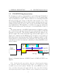
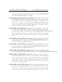
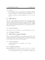
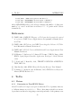
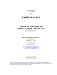
The current structure of the EPICS implementation is illustrated in Figure 1. Data flows both ways between the crate and the IOC via TCP/IP
(typically on port 2527). The data flow within the IOC App differs for input and output. The red line in the IOC App indicates that output records
simply send commands (via the HVWrapper), but input records actually get
their values from a data structure filled by the scan function which does the
actual extraction of data from the crate (blue line). The driver supports the
scan function and the data structure, primarily providing initialization and
service routines.
CAEN
HV
Wrapper
CAEN
x527 Crate
Driver Support
Scan Func. Data Struct
TCP/IP
IOC App
Device
Support
Input PVs
Output PVs
Other PVs
Figure 1: Schematic Structure of EPICS Control of CAEN x527 HV Power
Supplies.
Note: At the time this was written, only basic channel-specific features
are supported. Board- and Crate-specific features are expected to be added
in future versions of the software. Further, the current EPICS records are
basic, providing only input and output with the crate, some limit checking,
and engineering units for display. Features such as Alarms have not yet been
5
2 USE OF EPICS SOFTWARE
implemented.
2
Use of Epics Software
The GUI API of choice for general purposes at the CLS is EDM [6]. The
user control interface described here has been constructed with EDM, which
serves both functions of application editor and user interface. It is designed
specifically for communication with an EPICS-based control system.
2.1
Basic Graphical User Interface
There are three types of standard EDM GUIs to control or monitor a CAEN
x527. In all cases, text fields used for changing values must be activated by
pressing <return> or <enter>.
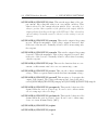
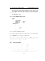
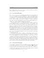
The simplest GUI, shown in Figure 2, controls only energizing or deenergizing the output of channels, and monitors the output voltage, output
current, and status. The output is energized when the “HV on/off” button
is depressed. Pressing the button again will de-energize the output. There is
no bias control.
6
2 USE OF EPICS SOFTWARE
2.1 Basic Graphical User Interface
Figure 2: Simplest User Interface
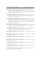
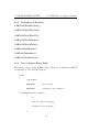
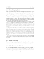
The standard interface, shown in Figure 3, has control for the voltage
setting as well as turning output on or off, and also monitors output voltage,
output current, and status. As with the simple GUI, the output is energized
when the “HV on/off” button is depressed. Pressing the button again will deenergize the output. The voltage can be set to a particular value simply by
entering a number in the “Setpoint” field of the requisite channel. Relative or
incremental changes can be made simply by pressing the “up” or “dn” buttons.
The increment is the (changeable) value entered in the “deltav” field of the
respective channel.
7
2.1 Basic Graphical User Interface
2 USE OF EPICS SOFTWARE
Figure 3: Standard User Interface
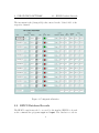
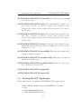
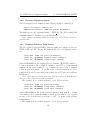
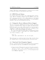
The Expert or Configuration GUI, shown in Figure 4, has most of the
controls available from EPICS, as well as monitors for output voltage, output
current, and status. Most of the additional controls are implemented as
text entry fields. As with the standard GUI, the output is energized when
the “HV on/off” button is depressed. Pressing the button again will deenergize the output. The voltage can be set to a particular value simply by
entering a number in the “Setpoint” field of the requisite channel. Relative or
incremental changes can be made simply by pressing the “up” or “dn” buttons.
8
2 USE OF EPICS SOFTWARE
2.2 EPICS Database Records
The increment is the (changeable) value entered in the “deltav” field of the
respective channel.
Figure 4: Configuration Interface
2.2
EPICS Database Records
The EPICS controls may also be accessed by the standard EPICS tools such
as the command line programs caget and caput. The database records are
9
2.2 EPICS Database Records
2 USE OF EPICS SOFTWARE
described below for the sake of both EPICS programmers and users who wish
to communicate with the controls by other means.
10
2 USE OF EPICS SOFTWARE
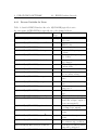
2.2.1
2.2 EPICS Database Records
Process Variables for Users
Table 1: Settable EPICS Database Records. $(PSNAME) typically is set to
the crate name, $(CHANNUM) is typically set to the channel address.
Process Variable Name
Record
Description
Type
$(PSNAME):$(CHANNUM):name
stringout Set name of channel, set in
the crate.
$(PSNAME):$(CHANNUM):name.DESC
char[29] Set name of channel in
EPICS only.
$(PSNAME):$(CHANNUM):v0set
ao
Set voltage setpoint.
$(PSNAME):$(CHANNUM):v0set:up
bo
Increase Voltage setpoint by
“deltav”
$(PSNAME):$(CHANNUM):v0set:dn
bo
Decrease Voltage setpoint
by “deltav”
$(PSNAME):$(CHANNUM):v0set:deltav
ao
Step size of incremental voltage changes.
$(PSNAME):$(CHANNUM):v1set
ao
Set voltage setpoint, secondary value.
$(PSNAME):$(CHANNUM):i0set
ao
Set software current limit.
$(PSNAME):$(CHANNUM):i1set
ao
Set software current limit,
for secondary voltage.
$(PSNAME):$(CHANNUM):rampup
ao
Set voltage increase ramp
rate.
$(PSNAME):$(CHANNUM):rampdn
ao
Set voltage decrease ramp
rate.
$(PSNAME):$(CHANNUM):trip
ao
Set over-current condition
trip period.
$(PSNAME):$(CHANNUM):svmax
ao
Set software maximum voltage.
$(PSNAME):$(CHANNUM):pwonoff
bo
Turn on/off channel output.
$(PSNAME):$(CHANNUM):pwupmode
bo
Set power-up mode (automatically energize output or
leave un-energized).
$(PSNAME):$(CHANNUM):pwdnmode
bo
Set power-down mode (kill
or ramp-down output).
$(PSNAME):$(CHANNUM):tripint
longout Set internal trip connections.
$(PSNAME):$(CHANNUM):tripext11
longout Set external trip connections.
$(PSNAME):$(CHANNUM):ilock:in.INP
ai
Set name of PV to monitor
for software trip condition.
$(PSNAME):$(CHANNUM):ilock:thresh
ao
Threshold at which software
trip will be triggered.
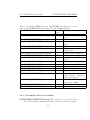
2.2 EPICS Database Records
2 USE OF EPICS SOFTWARE
Table 2: Read-Only EPICS Records. $(PSNAME) typically is set to the
crate name, $(CHANNUM) is typically set to the channel address.
Process Variable Name
Record
Description
Type
$(PSNAME):$(CHANNUM):name:fbk
stringin Name of channel set in the
crate.
$(PSNAME):$(CHANNUM):v0set:fbk
ai
Voltage setpoint.
$(PSNAME):$(CHANNUM):v1set:fbk
ai
Voltage setpoint, secondary
value.
$(PSNAME):$(CHANNUM):i0set:fbk
ai
Software current limit.
$(PSNAME):$(CHANNUM):i1set:fbk
ai
Software current limit, secondary value.
$(PSNAME):$(CHANNUM):rampup:fbk
ai
Voltage increase ramp rate.
$(PSNAME):$(CHANNUM):rampdn:fbk
ai
Voltage decrease ramp rate.
$(PSNAME):$(CHANNUM):trip:fbk
ai
Over-current condition trip
period.
$(PSNAME):$(CHANNUM):svmax:fbk
ai
Software maximum voltage.
$(PSNAME):$(CHANNUM):vmon
ai
Measured output voltage.
$(PSNAME):$(CHANNUM):imon
ai
Measured output current.
$(PSNAME):$(CHANNUM):status
mbbi
Channel status message.
$(PSNAME):$(CHANNUM):pwonoff:fbk
bi
Output on/off state.
$(PSNAME):$(CHANNUM):pwupmode:fbk bi
Power-up mode (automatically energize output or
leave un-energized).
$(PSNAME):$(CHANNUM):pwdnmode:fbk bi
Power-down mode (kill or
ramp-down output).
$(PSNAME):$(CHANNUM):tripint:fbk
longin
Internal trip connections.
$(PSNAME):$(CHANNUM):tripext:fbk
longin
External trip connections.
2.2.2
Description of Process Variables
$(PSNAME):$(CHANNUM):name The crate stores a label and this
label can be changed with this PV. Hence, if the user wished to assign a
12
2 USE OF EPICS SOFTWARE
2.2 EPICS Database Records
label that will appear on any kind of interface (e.g. the CAEN TELNET
screen), then this is the label to change.
$(PSNAME):$(CHANNUM):name.DESC This channel label is stored
only in EPICS. Changes to this will not propagate to the crate, and the
label will not persist between IOC restarts (unless a default is set in
the record, or a script or routine sets it after initialization). This would
be used if the user wants to assign a temporary or otherwise localized
label (e.g. detector used only for one week).
$(PSNAME):$(CHANNUM):v0set This sets the voltage of the channel. This is the default PV for setting voltages. This does not necessarily energize the output of the channel (see $(PSNAME):$(CHANNUM):pwonoff).
Note: currently, it is always a positive value regardless of the polarity
of the output, with the output polarity depending on the type of the HV
board.
$(PSNAME):$(CHANNUM):v0set:up This incrementally increases the
voltage setting of the channel by $(PSNAME):$(CHANNUM):deltav.
It is strictly binary, actuating when set on.
$(PSNAME):$(CHANNUM):v0set:dn This incrementally decreases the
voltage setting of the channel by $(PSNAME):$(CHANNUM):deltav.
It is strictly binary, actuating when set on.
$(PSNAME):$(CHANNUM):v0set:deltav This is the voltage increment
used by $(PSNAME):$(CHANNUM):v0set:up and $(PSNAME):$(CHANNUM):v0set:dn.
$(PSNAME):$(CHANNUM):v1set This sets the secondary voltage of
the channel. This value is selected by the voltage selection switch.
Note: currently, it is always a positive value regardless of the polarity
of the output, with the output polarity depending on the type of the HV
board. Note: Secondary voltage settings currently cannot be selected, so
this setting is not yet relevant.
$(PSNAME):$(CHANNUM):i0set This sets the upper limit of the output current. Exceeding this value is an over-current condition. Note:
currently, it is always a positive value regardless of the polarity of the
output, with the output polarity depending on the type of the HV board.
13
2.2 EPICS Database Records
2 USE OF EPICS SOFTWARE
$(PSNAME):$(CHANNUM):i1set This sets the upper limit of the output current. Exceeding this value is an over-current condition. This
value is selected by the current selection switch. Note: currently, it is
always a positive value regardless of the polarity of the output, with the
output polarity depending on the type of the HV board. Note: Secondary
current settings currently cannot be selected, so this setting is not yet
relevant.
$(PSNAME):$(CHANNUM):rampup This sets the output voltage rampup rate. When the magnitude of the voltage output is increased, this
is the rate of the increase. Naturally, it has no effect on increasing only
the setpoint.
$(PSNAME):$(CHANNUM):rampdn This sets the output voltage rampdown rate. When the magnitude of the voltage output is decreased, this
is the rate of the decrease. Naturally, it has no effect when decreasing
only the setpoint.
$(PSNAME):$(CHANNUM):trip This sets the duration that an overcurrent condition must exist before an over-current trip occurs.
$(PSNAME):$(CHANNUM):svmax This sets the software maximum
voltage. This is a separate limit from the hardware maximum voltage.
$(PSNAME):$(CHANNUM):pwonoff This energizes or de-energizes the
output of the channel. The voltage will ramp up and down by the rates
set in $(PSNAME):$(CHANNUM):rampup and $(PSNAME):$(CHANNUM):rampdn.
$(PSNAME):$(CHANNUM):pwupmode This sets the behaviour of the
channel when the crate is powered up. It can be set to either remain
off or to ramp up to the set voltage.
$(PSNAME):$(CHANNUM):pwdnmode This sets the behaviour of the
channel when the crate is powered down. It can be set to either ramp
down or to turn off immediately (“kill”).
$(PSNAME):$(CHANNUM):tripint
$(PSNAME):$(CHANNUM):tripext
14
2 USE OF EPICS SOFTWARE
2.2 EPICS Database Records
$(PSNAME):$(CHANNUM):ilock:in.INP The INP field of this record
should be set to the name of the PV to be monitored that will cause
the associated HV channel to trip via software. Don’t forget to add the
“CPP” qualifier to this field value.
$(PSNAME):$(CHANNUM):ilock:thresh This sets the threshold at
which the monitored PV will cause the associated HV channel to shut
down or turn on via software.
$(PSNAME):$(CHANNUM):ilock:cond This sets the type of condition that will cause the associated HV channel to shut down or turn on
via software. Valid types are “>”, “=”, “<”, and “!=”, corresponding to
whether the monitored value is greater than, equal to, less than, or not
equal to the threshold value.
$(PSNAME):$(CHANNUM):ilock:act.DOL1 This is set to the value
to set the associated HV channel when the software trip is triggered.
It should normally be either “ON” or “OFF”.
$(PSNAME):$(CHANNUM):name:fbk The label for this channel stored
by the crate. This label will persist between power cycles.
$(PSNAME):$(CHANNUM):v0set:fbk The voltage setting stored in
the crate.
$(PSNAME):$(CHANNUM):v1set:fbk The secondary voltage setting
stored in the crate.
$(PSNAME):$(CHANNUM):i0set:fbk The current setting stored in the
crate.
$(PSNAME):$(CHANNUM):i1set:fbk The secondary current setting
stored in the crate.
$(PSNAME):$(CHANNUM):rampup:fbk The ramp-up setting stored
in the crate.
$(PSNAME):$(CHANNUM):rampdn:fbk The ramp-down setting stored
in the crate.
$(PSNAME):$(CHANNUM):trip:fbk The over-current condition duration setting stored in the crate.
15
2.3 Starting the IOC Application
2 USE OF EPICS SOFTWARE
$(PSNAME):$(CHANNUM):svmax:fbk The software voltage maximum
stored in the crate.
$(PSNAME):$(CHANNUM):vmon The actual measured voltage output. Note: currently, it is always a positive value regardless of the
polarity of the output, with the output polarity depending on the type of
the HV board.
$(PSNAME):$(CHANNUM):imon The actual measured current output. Note: currently, it is always a positive value regardless of the
polarity of the output, with the output polarity depending on the type of
the HV board.
$(PSNAME):$(CHANNUM):status The status of the channel. For example, this will indicate if the voltage is ramping up or down, or if the
channel is on or off.
$(PSNAME):$(CHANNUM):pwonoff:fbk This indicates whether the
channel’s output is energized.
$(PSNAME):$(CHANNUM):pwupmode:fbk This is the power-up mode
setting stored in the crate.
$(PSNAME):$(CHANNUM):pwdnmode:fbk This is the power-down
mode setting stored in the crate.
$(PSNAME):$(CHANNUM):tripint:fbk
$(PSNAME):$(CHANNUM):tripext:fbk
2.3
Starting the IOC Application
The normal syntax for starting the HVCAENx257 IOC application is,
<EPICS_INSTALL_PATH>/bin/<arch>/HVCAENx527 <st.cmd>
-d -D 0
-c <Crate0Name>@<Crate0 IP>
[-c <Crate1Name>@<Crate1 IP>]
16
3 PROGRAMMING NOTES
where <EPICS_INSTALL_PATH> is where you installed the IOC application,
<arch> is the system architecture you are running the application on, <st.cmd>
is the usual EPICS “st.cmd” file, <Crate0Name> is a name that the crate will
use to associate commands meant for it, <Crate0IP> is the IP address or
name for the crate. There can be multiple instances of the “-c” option to
account for multple crates. The “-D” option is to set debugging level, which
is mostly for development purposes and normally should be set to 0 (no
debugging).
3
3.1
Programming Notes
Files
license.txt
license CAEN.txt License agreement text included for clarification. CAEN
wrapper must be obtained separately
Makefile
HVCAENx527App/src
HVCAENx527Main.cpp For linux-x86 IOCs, this is the main().
HVCAENx527.c
HVCAENx527.h
HVCAENx527Include.dbd
HVCAENx527chAio.c
HVCAENx527chBio.c
HVCAENx527chLongio.c
HVCAENx527chMBBio.c
HVCAENx527chStringio.c
Makefile
HVCAENx527App/Db
HVCAENx527.tpl
17
3.2 CAEN HVWrapper
3 PROGRAMMING NOTES
HVCAENx527ch.tpl
HVCAENx527chItLk.tpl
HVCAENx527ch.sub
HVCAENx527chItLk.sub
Makefile
iocBoot/iocHVCAENx527
st.cmd
clsHV Sample script for starting IOC application as a linux daemon.
opi
HVCAENx527config.edl
HVCAENx527.edl
HVCAENx527simple.edl
runCAENHV Sample script for starting EDM GUI.
3.2
CAEN HVWrapper
The functions for the CAEN HV Wrapper are quite well documented in the
wrapper’s manual[1]. The EPICS driver is based on calls to these functions.
The following HVWrapper functions were used for this EPICS implementation.
CAENHVInitSystem()
CAENHVDeinitSystem()
CAENHVGetChName()
CAENHVSetChName()
CAENHVGetChParamInfo()
CAENHVGetChParamProp()
CAENHVGetChParam()
CAENHVSetChParam()
CAENHVGetCrateMap()
Note: Board and crate support routines will be added to this list when
board and crate parameters are added to the EPICS database.
18
3 PROGRAMMING NOTES
3.3
3.3.1
3.3 Installation
Installation
Requirements
Installation of HVCAENx527 requires:
• the CAEN wrapper libraries which you must get from CAEN directly
(registration is free and seems benign).
• a local installation of “msi”, the epics “Macro Substitution and Include
Tool”
3.3.2
Building
• Get a copy of the gzipped tar file, “HVCAENx527_<version>.tgz”, where
<version> is the version of the driver.
• Create and change to a working directory for building the driver.
> tar -z -x -f HVCAENx527_<version>.tgz
This should build a standard EPICS 3.14.6 build directory named
“HVCAENx527”.
• Change directory:
> cd HVCAENx527
• You probably have to force a reconfiguration, so
> make clean uninstall install
• The account name and password for crate access is hardcoded, so you
will have to change all instances of them. Assuming you are still in
directory “HVCAENx527”, change to directory “HVCAENx527App/src”.
– Edit the file HVCAENx527.c
19
3.3 Installation
3 PROGRAMMING NOTES
– Look for calls to function “CAENHVInitSystem” and change all
instances of “admin” to the respective account name and passwords
on the crate you want to connect to.
Note: If you have multiple crates with different passwords you will
have to either make them the same or run different instances of
this IOC. That’s an oversight to be dealt with in later versions.
• Next, the db records have to be configured.
– Change to directory “HVCAENx527/Db” (e.g. in Linux if you are in
src, ’cd ../Db’). You should see files with names suffixed with
“.sub”. These are “msi” substitution files.
∗ If you do not have “msi” or prefer to hand build your db files,
you should at least use the template files (“.tpl” suffix) as the
basis.
– Edit the substitution files and change entries corresponding to
“PSNAME” to the basename you need.
∗ In file “HVCAENx527ch.sub”, add or delete entries for channels
you want to provide support for. There are sample entries
provided, so be sure to delete or change those.
∗ File “HVCAENx527chItLk.sub” is for interlocking HV channels
to external EPICS PVs. Add or delete entries as needed.
There is one provided as an example, so be sure to change or
delete it.
• Change directories back to “HVCAENx527”.
• run ’make’
• Change directory to “iocBoot/iocHVCAENx527”, and edit st.cmd.
– Change the entries for dbLoadRecords() to point to the “db” files
that were built above.
– You may also have to change the top line (“#!../../bin...”) to
match how your EPICS system is layed out.
20
3 PROGRAMMING NOTES
3.3.3
3.4 EPICS Driver
Install
• Since installations tend to be quite different, an installation script has
not been provided. It is assumed that the local facility has its own
scripts for this purpose, or that the developer has the means to do so.
The files to install are the standard EPICS ones: bin, db, dbd, and
iocBoot.
3.4
EPICS Driver
The driver consists of functions and subroutines that communicate with the
x527 crate via the HVWrapper, but have no contact with EPICS. These
routines typically take care of initializing and shutting down crate communications, as well as initializing and destroying data structures used by EPICS
support routines. But the primary function is to periodically scan the crate
for relevant parameters.
3.4.1
Syntax of Routines
The following routines should NOT be used in any EPICS support routines.
3.4.2
3.5
Description of Routines
EPICS Driver Support Routines
These are routines that EPICS can use to interact with the driver. The
routines simply initialize or shutdown the IOC. The routines discussed here
are intended for use in driver support entry tables, but they also can appear
in device support entry tables if conditions require it.
3.5.1
Syntax of Routines
void ParseCrateAddr( char (*straddr)[], short naddr);
void Shutdown();
3.5.2
Description of Routines
ParseCrateAddr() This subroutine performs two functions: determines
the crate’s IP address if given the crate’s host name, connects to the
crate, and initializes all crate, board, and channel data structures. In
21
3.6 EPICS Device Support Routines
3 PROGRAMMING NOTES
light of the latter, the subroutine is misnamed. The IP address is determined with the system host name resolution function gethostbyname().
Shutdown() This subroutine deallocates data structures, and shuts down
all connections to crate.
3.5.3
Driver Support Entry Table
struct
{
long number;
DRVSUPFUN
report;
DRVSUPFUN
init;
} drvCAENx527 =
{
2,
report,
init
};
3.5.4
Database Definition Syntax
Note: database definition syntax for the driver have yet to be implemented.
3.6
EPICS Device Support Routines
Device support routines provide the interaction of EPICS with either the
driver or the crate through the driver. The routines discussed here are intended for use in device support entry tables.
3.6.1
Syntax of Routines
void *CAENx527ParseDevArgs( char *saddr);
void *CAENx527GetChParVal( PARPROP *pp);
int CAENx527SetChParVal( PARPROP *pp);
char *CAENx527GetChName( HVCHAN *hvch);
int CAENx527SetChName( HVCHAN *hvch, char *chname);
short CAENx527mbbi2state( PARPROP *pp);
void CAENx527mbbi2bits( PARPROP *pp, char *bits, short nbits);
char *CAENx527GetParUnit( PARPROP *pp, char *fieldval);
22
3 PROGRAMMING NOTES
3.6.2
3.6 EPICS Device Support Routines
Description of Routines
CAENx527ParseDevArgs()
CAENx527GetChParVal()
CAENx527SetChParVal()
CAENx527GetChName()
CAENx527SetChName()
CAENx527mbbi2state()
CAENx527mbbi2bits()
CAENx527GetParUnit()
3.6.3
Device Support Entry Table
The format of Device Support Entry Tables (dset) are documented in EPICS
documentation. The relevant parts are
struct
{
long number;
...
DEVSUPFUN
init_record;
...
DEVSUPFUN
read/write_<recordtype>;
...
} devCAENx527ch<recordtype> =
{
6;
...
init_record_<recordtype>,
...
read/write_<recordtype>,
...
};
23
3.6 EPICS Device Support Routines
3.6.4
3 PROGRAMMING NOTES
Database Definition Syntax
The following device() definition entry syntax pertains to channel I/O.
device( <recordtype>, INST_IO, devCAENx527ch<recordtype>, "CAEN x527 generic HV Channel")
The link type (second argument) must be INST IO. The choice string (4th
argument) must be ”CAEN x527 generic HV Channel”.
Note: database definition syntax for board and crate I/O have yet to be
implemented.
3.6.5
Required Database Field Syntax
The two required fields in EPICS database input and output records are
DTYP, OUT, and INP. For the HV channels, the db record syntax for these
are
field( DTYP, "CAEN x527 generic HV Channel")
field( OUT, "@$(CHADDR) <channel output command>")
field( INP, "@$(CHADDR) <channel input command")
where $(CHADDR) is the channel address, formatted R.SS.CCC with R =
1-digit crate number, SS = 2-digit slot number, and CCC = 3-digit channel
number, all left padded with “0”, e.g. a channel in crate 2, slot 4, channel
6 has an address 2.04.006. “@” prefix on the address is mandatory. This
format was chosen because that is the format the x527 crate uses with the
HVWrapper.
Note: field syntax for board and crate I/O have yet to be implemented.
The proceeding discussion is only a proposal.
The required db record field syntax for board I/O records are
field( DTYP, "CAEN x527 generic HV Board")
field( OUT, "@$(BDADDR) <board output command>")
field( INP, "@$(BDADDR) <board input command>")
where $(BDADDR) is the board address, formatted R.SS with R = 1-digit
crate number, SS = 2-digit slot number, all left padded with “0”, e.g. a board
in crate 3, slot 1 would have an address of “3.01”. “@” prefix on the address
is mandatory.
The required db record field syntax for board I/O records are
24
4 TO DO
REFERENCES
field( DTYP, "CAEN x527 generic HV Crate")
field( OUT, "@$(CRADDR) <board output command>")
field( INP, "@$(CRADDR) <board input command>")
where $(CRADDR) is the board address, formatted R with R = 1-digit crate
number, e.g. crate 3 would have an address of “3”. “@” prefix on the address
is mandatory.
References
[1] CAEN, 2002, CAEN HV Wrapper, a C Library which permits the control
of a generic CAEN Power Supply System Programmer’s Manual, Revision N.09.
[2] CAEN, 2004, OPC Server for CAEN Power Supplies, Release 2.X, Technical Information Manual, Revision n.5.
[3] CAEN, 2005, SY2527, Universal Multichannel Power Supply System User
Manual, Revision 9.
[4] M. Kramer, J. Anderson, A. Johnson, E. Norum, J. Hill, R. Lange, 2004,
EPICS: Input/Ouput Controller Application Developer’s Guide, Release
3.14.6
[5] J. Postel and J. Reynolds, 1993, TELNET PROTOCOL SPECIFICATION, RFC 854.
[6] John Sinclair, 2002, EDM: Extensible Display Manager User Manual.
[7] P. Stanley, J. Anderson, and M. Kramer, 1995, EPICS Record Reference
Manual, EPICS Release 3.13
4
4.1
4.1.1
To Do
Driver
Conversion to True EPICS Driver
Most PVs will need longer scan periods than the PVs of primary interest,
so different timers are needed, too. These other timers should not run independent scan threads, triggering scans independently of the primary scan
25
4.1 Driver
4 TO DO
thread. Rather, they should only be used to notify the primary scan thread
that a particular scan period has elapsed.
4.1.2
Scan Period Recoding
The concept of scan periods is currently implemented incorrectly. This was
due to poor planning more than anything else. Most of the EPICS input
records have periodic scanning activated, the scan thread has multiple timers
corresponding to groups of PVs with different priorities, the scan thread
has it’s own base timer, and periods are assigned according to parameter
type. The worst problem is that all of these are independent, which leads to
confusion as to what actually determines the scan rate.
As long as the concept of a central scan thread remains, at the very
least the EPICS input record SCAN fields should be set to passive, and
the device support routines should return to performing dbPutField() to the
input record. That leaves the matter of the other timers, which are needed to
implement multiple scan periods, as discussed in Subsection 4.1.1. Finally,
the scan lists should be first associated to a particular timer, then subdivided
by parameter type. The reason for sub-lists by parameter type is that the
CAEN HVWrapper functions can send values in bulk according to parameter
type. So as soon as a timer has lapsed, the associated scan list loops through
its parameter scan lists.
An alternative is to build a command queuing thread into the driver,
then activate the SCAN periods in the input records. This may be required
if a crate has multiple users (rather than multiple connections), or if “set”
commands look like they are interfering with scans or vice versa. This thread
should be started at IOC initialization. It would build a linked list (forward
link should be sufficient) of command structs, adding a link to the end when
a new request is queued and removing the link at the start when a request
has been serviced. Two pointers should track the first and last link.
4.1.3
Scan period debugging
To aid with the assignment of timers, the EPICS routine scan period() could
be used, IF scan periods are to be based on record SCAN fields. It would have
been incorporated for the current version but the routine caused crashes. So
basically, work on this aspect of the driver is a debugging exercise, or should
be abandoned if SCAN fields are not to be used.
26
4 TO DO
4.1.4
4.1 Driver
Writes Triggering Reads
Many of the parameters are quite static, with interest in the feedback of their
values only to confirm a change, or to occasionally check that there is nothing
noteworthy of the parameter’s value. For these, the corresponding network
traffic and CPU usage can be reduced if the scan period is set quite long.
However, after a parameter is set, it should be (and is) scanned immediately.
There occasionally is some lag between a setpoint being sent and the crate
actually registering a change. The result is that the setpoint feedback PV
does not get an updated value. One solution might be to temporarily make
the scan period shorter after the user has set a new value.
For an extreme example, the ramp-up parameter’s read scan period could
be set to 5 minutes, but when the user sets the ramp-up to a new value, it
would temporarily scan that parameter every second for ten seconds, and
then go back to scanning every 5 minutes. Actually, the quick scan could
be set up as a short-lived thread, shutting it down after the 10 seconds have
passed.
The problem with the above is that it should be simple to implement
if the scan routine controls the scan periods, but implementing it when the
input record controls the scan period would be more complicated (i.e. there
would not be a central scan routine). In that case a separate (temporary?)
scan thread would be needed and have to perform a dbPutField() into the
value field of the input record independently of the scanning activity of the
record.
Of course, the idea of a temporary fast scan would be unnecesary if the
crate response is adequate for simply setting then promptly reading back the
set point.
4.1.5
Setting Scan Periods
If scan periods are centralized (e.g. by the continued use of the central scan
routine), some PVs should be added to set and display the scan period.
4.1.6
Other Communication Methods
Do not bother implementing an RS-232 variant of the driver (actually, it
only requires setting a software switch in the HVWrapper). The Ethernet
version drives approximately 3 to 12 kB/s in each direction when servicing 24
27
4.2 EPICS Record Alarms
4 TO DO
channels. While this is certainly manageable for current serial cards, queuing
problems will be much worse than with the network setup.
4.2
EPICS Record Alarms
Some channel parameters have limits, some of which may well be crucial to
a user. There are currently no alarms set up in the EPICS records for the
x527. Alarm support should be added, perhaps making use of the Minval
and Maxval fields of the channel property structure, or at least initialized
with them. This is probably the highest priority item.
4.3
Parsing the Device Address in Device Support
The device address parser, CAENx527ParseDevArgs(), currently only handles
addresses for channel I/O. Three changes are required: the string from the
DTYP field must be parsed with a different method, the data type must be
determined according to the address type (crate, slot, or channel), and the
return value reconciled with address type and existing use.
The core problem is that the DTYP string is currently parsed directly
to crate number, slot number, channel number and command assuming the
exact format for channels, i.e. with
narg = sscanf( saddr, "%hd.%hd.%hd %s", &cr, &sl, &ch, pnm);
This is inadequate for a variably structured address. Hence, first the address
and command should be extract separately then the address type parsed.
4.4
Board and Crate Parameter Support
The type of parameters that should have the highest priority for parameters
are crate status and crate-wide control EPICS records. In particular,
• Connection status. If the network connection is lost, the user interface
will show no response. There is information available in the driver
indicating the connection has been lost, so a PV indicating this should
not be difficult to implement.
28
4 TO DO
4.5 Polarity
• Crate status. Many fault conditions are associated with individual
channels, so there are not many similar parameters associated with the
crate. But if there are any crate-specific parameters, some of them
should have a PV.
• Board status. A multi-bit field could be used to indicate which slots
have active boards, and perhaps alarms to indicate status.
Other lower priority parameters for consideration are:
• Crate-wide HV on/off. This might instead be an emergency off. The
problem with making this truly crate-wide is that if there are multiple
users using different channels, it would interfere with their apparatus.
This might be better implemented either in the GUI or as a custom
IOC record rather than incorporating it in the general code.
Most of the above do not have a corresponding parameter in the HVWrapper.
They would have to be implemented in EPICS or at higher levels, in user
interfaces.
There are a number of parameters to control and monitor the crate and
boards in the crate. The wrapper has functions that access this information similarly to the way it accesses channel information. Thus, parameter
structure lists should be added to the board and slot structures. Device
support routines analogous to the ones for channel support should be added
for board and crate parameters. The scan rate or priority for most of these
should be the lowest since most are rather static. However, note that there
are not many parameters that would be of interest to users, so this should
be considered a low priority item.
4.5
Polarity
Some CAEN HV modules have a fixed polarity, that is, positive bias modules
and negative bias modules. For those modules, the crate reports and expects
only the magnitude of the bias. The polarity is not obvious at the user
interface. There are two schools of thought on the issue. Users who know the
device, particularly what bias it requires, will expect to input voltages with
the appropriate sign and the lack of it in the display may confuse the user. On
the other hand, forgetting to set the sign appropriately is a common mistake
when manually entering a voltage. If the former is favoured, conversion
29
4.6 Host Name Lookup
4 TO DO
will have to be added to device support. There are at least two ways of
implementing this conversion.
At init_record(), the board type is known and can be used to set up
record conversion (e.g. set ASLO or ESLO). Then, record conversion should
be turned on (the default is to bypass conversion - this may require extra
code in read_ao() and write_ao()).
Alternatively, all conversion could be done in read_ao() and write_ao().
4.6
Host Name Lookup
For portability, EPICS routines for host name lookup should be used instead
of gethostbyname(). That is, consider using aToIPAddr().
4.7
Name and Password on Crates
Currently, the name and password on a given crate is hardcoded right in
the call to initialize a crate. This must be made dynamic, to some extent, to
accommodate systems where each crate has a different user name or password
in each crate. For obvious security reasons, this should NOT be a command
line option, nor should it be in user accessible configuration files.
30