1
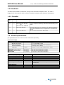
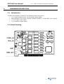
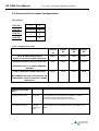
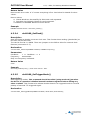
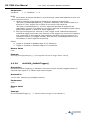
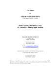
DA11000-4M
DA11000-16M
1 Channel, 1 GS/s, 12-Bit, PCI Bus
Arbitrary Waveform Generator Card
User Manual
February 2008
Information in this document is subject to change without notice.
© Copyright 2004, Acquitek, SAS. All rights reserved.
Acquitek is a trademark of Acquitek, SAS. Other trademarks and trade names may be used in
this document to refer to either the entities claiming the marks and names or their products.
Acquitek disclaims any proprietary interest in trademarks and trade names other than its own.
Acquitek makes no warranty of any kind with regard to this material, including, but not
limited to, the implied warranties of merchantability and fitness for a particular purpose.
Acquitek shall not be liable for errors contained herein or for incidental or consequential
damages in connection with the furnishing, performance, or use of this manual.
Acquitek, SAS.
1 bis Rue Marcel Paul,
91300 Massy
France
Email: [email protected]
Web: http://www.acquitek.com
DA11000 User Manual
1-Ch, 1GS/s, PCI Arbitrary Waveform Generator
TABLE OF CONTENTS
1
GENERAL INFORMATION.......................................................................................................................3
1.1 INTRODUCTION ............................................................................................................................................3
1.2 REFERENCES.................................................................................................................................................3
1.3 DELIVERABLES .............................................................................................................................................4
1.3.1
Software ......................................................................................................................................4
1.3.2
Hardware ....................................................................................................................................5
1.3.3
Checklist ......................................................................................................................................5
1.4 PRODUCT SPECIFICATION ...........................................................................................................................5
1.5 OPTION SUMMARY .......................................................................................................................................7
1.6 TECHNICAL SUPPORT / SOFTWARE UPDATES ...........................................................................................7
1.7 WARRANTY ...................................................................................................................................................8
2
HARDWARE DESCRIPTION...................................................................................................................9
2.1
2.2
2.3
2.4
3
THEORY OF OPERATION ......................................................................................................................11
3.1
3.2
4
INTRODUCTION ............................................................................................................................................9
BOARD DRAWING ........................................................................................................................................9
EXTERNAL CLOCK JUMPER CONFIGURATIONS .........................................................................................10
PCI MEMORY ALLOCATION .......................................................................................................................11
INTRODUCTION ..........................................................................................................................................11
DOWNLOADING AND OUTPUTTING USER DATA TO THE DA11000......................................................11
SOFTWARE DRIVERS .............................................................................................................................12
4.1 INTRODUCTION ..........................................................................................................................................12
4.2 DRIVER INSTALLATION WINDOWS 2000 / XP ......................................................................................12
4.3 FUNCTION CALLS .......................................................................................................................................13
4.3.1
C Header File for DLL .........................................................................................................13
4.3.2
Function Call Descriptions / Usage...........................................................................13
4.3.2.1
4.3.2.2
4.3.2.3
4.3.2.4
4.3.2.5
4.3.2.6
4.3.2.7
4.3.2.8
4.3.2.9
4.3.2.10
4.4
5
da11000_CountCards() ..................................................................................................................... 13
da11000_Open() .................................................................................................................................. 14
da11000_Close().................................................................................................................................. 14
da11000_SetClock() ........................................................................................................................... 15
da11000_SetTriggerMode() ............................................................................................................. 15
da11000_SetSoftTrigger()................................................................................................................ 16
da11000_SetMarkers() ...................................................................................................................... 17
da11000_CreateSingleSegment() ................................................................................................. 18
da11000_ CreateSegments() .......................................................................................................... 19
da11000_UpdateSegmentCmds () ................................................................................................ 21
PROGRAMMING EXAMPLES ........................................................................................................................22
MISCELLANEOUS ......................................................................................................................................24
5.1
5.2
CALIBRATION .............................................................................................................................................24
MAINTENANCE ............................................................................................................................................24
2
DA11000 User Manual
1
1-Ch, 1 GS/s, PCI Arbitrary Waveform Generator
GENERAL INFORMATION
1.1 Introduction
The DA11000 is a (1) Channel, 12-bit, 1 Giga Sample/second Arbitrary Waveform
Generator on a single mid-sized PCI card. It comes standard with following general
features:
-
Standard fixed clock 1 GHz.
12-bit Vertical Resolution
(1) TTL Output Marker
Programmable Segment Size from 64 Words to full memory
Programmable Number of Segments up to 32K
External TTL clock and External TTL trigger input
The outputs consist of (1) 50 ohm SMA output.
To provide maximum flexibility and performance to the user, the output comes unfiltered,
although the output buffer BW is > 300 MHz at full scale. An appropriate low pass filter is
generally added in-line for a particular application and can be bought from companies like
Mini-Circuits or can be ordered and/or custom made directly from Acquitek.
The DA11000 has TTL input triggering capability that allows a segment or segments of data
to be output only after a trigger is present. Gating is also available which will start and stop
the data from being output on high or low TTL levels respectively.
An external TTL clock input allows the use of precision clock sources such and also for
synchronizing multiple cards to a master clock.
1.2 References
PCI Local Bus Specification, Rev. 2.1, June 1st, 1995. For more information on this
document contact:
PCI Special Interest Group
P.O Box 14070
Portland, OR 97214
Phone (800) 433-5177 (U.S.)
(503) 797-4207 (International)
FAX
(503) 234-6762
3
DA11000 User Manual
1-Ch, 1GS/s, PCI Arbitrary Waveform Generator
1.3 Deliverables
1.3.1 Software
The DA11000 comes with DLL drivers for Windows 2000/XP. Software comes on a CD.
Call Acquitek for the latest information on drivers for other operating system platforms.
Windows 2K/XP software drivers are provided as a Dynamic Link Library (*.DLL) which
is compatible with most 32-bit windows based development software including Microsoft
C/C++, Borland C/C++, Borland Delphi, Visual Basic, LabVIEW and MATLAB script. This
DLL uses the “cdecl” calling convention for maximum compatibility and was made using
Borland C++ Builder. It automatically provides the interface to the system drivers
“Windrvr6.sys” for Windows 98/ME/NT4/2000/XP.
4
DA11000 User Manual
1-Ch, 1 GS/s, PCI Arbitrary Waveform Generator
1.3.2 Hardware
The DA11000 hardware consists of a single mid-sized PCI compliant card. The card is
shipped with this manual which includes complete hardware and software descriptions.
1.3.3 Checklist
Item
#
Qty
Part Number
1
1
2
1
DA11000-12-4M-PCI
Or
DA11000-12-16M-PCI
DA11000 Drivers
3
1
DA11000-Manual
Description
1-CH, 1GS/sec Arbitrary Waveform Generator, PCI
card.
CD with Dynamic Link Libraries for Windows2K/XP.
Includes standalone demo application and labView
driver
On CD User manual for DA11000.
1.4 Product Specification
(all specifications are at 25 ºC unless otherwise specified)
SPECIFICATIONS
Parameter
Analog Outputs
Number of Outputs
Output Coupling
Vertical Resolution
Amplitude
Rise Time (10% to 90%)
Fall Time (10% to 90%)
Clock Jitter
Internal Clock Rate
Frequency Range
Stability
Memory
Waveform
# of User Segments
Segment Size Range
Digital Outputs
(1) TTL Markers
Conditions
Typical Values unless otherwise indicated
1 GS/s
(1) 50 ohm SMA output
AC coupling through 50 ohm transformer
12 bits (1 part in 4096)
0.5Vpp +/-3%, single ended into 50 ohms.
No Filters
No Filters
1.0 GS/sec
300 pico sec typical into 50 ohms
300 pico sec typical into 50 ohms
Less than 20 psec RMS at 300MHz
T=0ºC – 70ºC
Standard
1.0 GHz fixed
100 ppm
4M Words x 12-bits (or 16M Words)
1 to 16K segments
64 Words up to total memory in 64 Word
increments
Fclk/4 resolution
5
DA11000 User Manual
1-Ch, 1GS/s, PCI Arbitrary Waveform Generator
Digital Inputs
High Speed Clk input
D/A rate
50 ohm SMA input
(Sinewave from 0dBm to 6 dBm)
Can only use the following frequencies:
1.0 GHz, 500 MHz, 250 MHz, and 125 MHz.
(See section 2.4 for jumper settings)
Low Speed Clk input
10 MHz
Reference Only
50 ohm SMA input (Sine/Square wave from 0dBm
to 10 dBm)
(See section 2.4 for jumper settings)
TTL Trigger input
ENVIRONMENTAL
Parameter
Temperature
Operating
Non-Operating
Humidity
Operating
Non-Operating
Power
+5V
+3.3V
+12V
-12V
Size
DA11000-12-4M-PCI
Used to initiate any memory segment programmed
for that purpose.
Typical Values unless otherwise stated
0 to 70 degrees C standard
-40 to +85 degrees C extended
5 to 95% non-condensing
20% to 80%
5% to 95%
+5V DC +/- 10% => 500mA, 2.5 Watts (Typical using worst case waveform)
+3.3 VDC +/- 10% => 2.5 Amps, 8.4 Watts (Typical using worst case waveform)
+12 VDC +/- 10% => 216mA, 2.6 Watts (Typical using worst case waveform)
-12 VDC +/- 10% => 100mA, 1.2 Watts (Typical using worst case waveform)
(1) Mid-Sized PCI Card
6
DA11000 User Manual
1-Ch, 1 GS/s, PCI Arbitrary Waveform Generator
1.5 Option Summary
OPTION SUMMARY
Option Name
Option 3
Description
Linux Driver
1.6 Technical Support / Software Updates
For technical support:
Phone:
Fax:
Email:
Mail:
+33 1 60 13 52 73
+33 1 60 13 03 68
[email protected]
Acquitek
1 bis rue Marcel Paul, 91300 Massy, France
For software updates:
Email:
Web:
[email protected]
http://www.acquitek.com
7
DA11000 User Manual
1-Ch, 1GS/s, PCI Arbitrary Waveform Generator
1.7 Warranty
Acquitek warrants to the original purchaser that it’s DA11000, and the component parts
thereof, will be free from defects in workmanship and materials for a period of ONE YEAR
from the data of purchase.
Acquitek will, without charge, repair or replace at its option, defective or component parts
upon delivery to Acquitek service department within the warranty period accompanied by
proof of purchase date in the form of a sales receipt.
EXCLUSIONS: This warranty does not apply in the event of misuse or abuse of the
product or as a result of unauthorized alterations or repairs. It is void if the serial number
is altered, defaced or removed.
Acquitek shall not be liable for any consequential damages, including without limitation
damages resulting from loss of use. Some states do not allow limitation or incidental or
consequential damages, so the above limitation or exclusion may not apply to you.
This warranty gives you specific rights. You may also have other rights that vary from
state to state.
NOTICE: Acquitek reserves the right to make changes and/or improvements in the
product(s) described in this manual at any time without notice.
8
DA11000 User Manual
2
1-Ch, 1 GS/s, PCI Arbitrary Waveform Generator
HARDWARE DESCRIPTION
2.1 Introduction
The DA11000 hardware consists of the following major connections:
• (1) 1 Giga Samples/second, 12-bit analog outputs (SMA)
•
•
•
PECL/Sinewave Clock Input, 125MHz, 250MHz, 500MHz, 1.0 GHz ONLY (AC coupled)
(1) TTL Trigger input (SMA)
(1) TTL Marker output (SMA)
2.2 Board Drawing
9
DA11000 User Manual
1-Ch, 1GS/s, PCI Arbitrary Waveform Generator
2.3 External Clock Jumper Configurations
JP2 (pinout)
JUMPER 1
1
2
JUMPER 2
3
4
JUMPER 3
5
6
JUMPER 4
7
8
Clock Configuration Table
#1
Jumper
#2
Jumper
#3
Jumper
#4
Use 1.0 GHz Internal Clock
locked to internal 10 MHz reference
SHORT
OPEN
OPEN
SHORT
Use External Clock at D/A clock rate
OPEN
SHORT
OPEN
SHORT
SHORT
OPEN
SHORT
OPEN
Jumper
Allowable rates = 1.0 GHz, 500 MHz,
250 MHz
Lock to External 10 MHz Reference
DA11000 Phase locks the internal 1.0
GHz master clock to external 10 MHz
Reference
External Clock Input
Notes
High Speed Clk input
D/A rate
50 ohm SMA input (Sinewave from 0dBm to 6 dBm)
Can only use the following frequencies:
1.0 GHz, 500 MHz, 250 MHz, and 125 MHz.
Low Speed Clk input
10 MHz
Reference
Only
50 ohm SMA input (Sine/Square wave from 0dBm to 10
dBm)
10
DA11000 User Manual
1-Ch, 1 GS/s, PCI Arbitrary Waveform Generator
2.4 PCI Memory Allocation
DA11000 on-board memory is mapped automatically when a PCI 2.1 (or newer)
motherboard powers up. If the DA11000 has 4 Mega Samples of memory, then the
motherboard will allocate 8 Megabytes of memory. Once installed, the DA11000 software
drivers will find the board or boards without the user changing any jumpers or worrying
about addressing.
How the memory is allocated and where it is located in the system is completely
transparent, unless the user manages to use up the entire memory available to the PCI
motherboard (usually 256 Megabytes or more).
3
THEORY OF OPERATION
3.1 Introduction
Although the DA11000 is primarily comprised of a Segment Sequencer (or memory
manager) and a 4:1 High Speed Multiplexer, it’s how the software interacts with the
hardware that makes it work. The following sections should provide enough operational
theory for better understanding when using the software drivers.
3.2 Downloading and Outputting User Data to the DA11000
The DA11000 RAM memory IC’s not only contain the user’s waveform data, but it also
contains special command codes that run the Segment Sequencer. These codes are placed
into the upper nibble (4 bits) of selected individual sample points (16 bit words), leaving
the lower 12 bits for user data. The Segment Sequencer reads these codes to determine
where and when to jump to another segment, how many times to loop, when to wait for a
trigger, and when to shut down. This is the heart of the DA11000 memory management.
Downloading a Single User Waveform (single segment) into memory is performed by simply
calling da11000_CreateSingleSegment(DWORD NumPoints, DWORD NumLoops, PVOID
UserArrayPtr, DWORD TrigEn). The user must be sure to pass the size of the waveform
(NumPoints), the number of times to repeat the waveform (NumLoops), a pointer variable
pointing to the user array containing the data (UserArrayPtr), and finally, whether the
segment will be self triggered or triggered by an external signal (TrigEn).
Downloading Multiple Linked Waveform Segments is performed by calling
da11000_CreateSegments(DWORD NumSegments, PVOID PtrToSegmentsList). This
function call requires the user to create a structure containing all the critical information on
the segments that the user wants to download. The actual structure for each segment looks
like the following:
typedef struct
{
DWORD
PVOID
SegmentNum;
SegmentPtr;
DWORD NumPoints;
DWORD NumLoops;
DWORD BeginPadVal;
DWORD EndingPadVal;
DWORD TrigEn;
DWORD NextSegNum;
ativities
} SegmentStruct;
// Current Segment Number
// Pointer to current user segment
// ==> elements of one diminsional array must be of type WORD
// Number of points in segment
// Number of times to repeat segment (applies to next segment)
// Pad value for beginning of triggered segment
// Pad value for ending of triggered segment
// If > 0 then wait for trigger before going to next segment.
// Next segment to jump to after completion of current segment
11
DA11000 User Manual
1-Ch, 1GS/s, PCI Arbitrary Waveform Generator
The user must create an array of these segments and pass the pointer (PtrToSegmentsList)
to the function call.
After the appropriate waveform data has been downloaded to the DA11000,
da11000_SetTriggerMode() is enabled and the output begins.
4
SOFTWARE DRIVERS
4.1 Introduction
Our primary objective in designing software drivers is to get the user up and running as
quickly as possible. While the details on individual function calls are listed in sections
4.2.xx, the programming examples in section 4.3.x will show you how to include them into
your programs. Please note that function calls are the same whether you are calling them
under Windows 95, 98, NT, 2k or XP.
4.2 Driver Installation Windows 2000 / XP
Be aware that we use the same driver for the DA4300 card.
1) Do not install DA11000 card at this time.
2) Run the setup located on the CD
This will copy the Kernel driver windrvr6.sys to "c:\<windir>\system32\drivers\" directory
and will register the Kernel driver in the Windows Registry so that it starts up each time the
computer is rebooted. It installs also a standalone demo software called DA11000 demo.
4) Power off computer, insert DA4300 card and Power up the computer.
5) When OS asks for Driver File point to "DA11000.inf" which is located on the CD root (or
on your DA11000 installation directory . If OS does not ask for file, then check hardware
configuration and update if not listed properly under "Jungo" in Device Manager (see
below).
To check to see which driver is installed, do the following:
=> Control Panel
=> System
=> Hardware
=> Device Manager
=> Jungo
DA11000 (Both this and WinDriver below should be present)
WinDriver
If you see another driver in place of " DA11000 ", then right click the first device under
Jungo and click properties. Update the driver by pointing to "DA11000 ". You may have
to go through a series of menus.
12
DA11000 User Manual
1-Ch, 1 GS/s, PCI Arbitrary Waveform Generator
4.3 Function Calls
4.3.1 C Header File for DLL
//--------------------------------------------------------------------------// USER ROUTINES
//--------------------------------------------------------------------------#define IMPORT extern "C" __declspec(dllimport)
IMPORT DWORD da11000_CountCards(void);
IMPORT DWORD da11000_Open(DWORD CardNum);
IMPORT DWORD da11000_Close(DWORD CardNum);
IMPORT void da11000_SetClock(DWORD CardNum, DWORD Frequency);
IMPORT void da11000_SetTriggerMode(DWORD CardNum, BYTE Mode, BYTE ExtPol);
IMPORT void da11000_SetSoftTrigger(DWORD CardNum);
IMPORT void da11000_SetMarkers(DWORD CardNum, DWORD PointAddr, BYTE Nib1, BYTE Nib2);
IMPORT void da11000_CreateSingleSegment(DWORD CardNum, DWORD ChanNum, DWORD NumPoints, DWORD
NumLoops, PVOID UserArrayPtr, DWORD TrigEn);
IMPORT void da11000_CreateSegments(DWORD CardNum, DWORD NumSegments, PVOID UserSegmentsPtr);
IMPORT void da11000_UpdateSegmentCmds(DWORD CardNum, DWORD NumSegments, PVOID PtrToSegmentsList);
4.3.2 Function Call Descriptions / Usage
4.3.2.1
da11000_CountCards()
Description
Returns number of DA11000 cards present on computer.
Declaration
DWORD da11000_CountCards(void);
Parameters
none
Return Value
Returns with an encoded value which represents the number of DA11000.
Return Values:
1-4: Number of DA11000 boards detected.
0: Indicates that no boards were found but that drivers are working properly.
13:
Software drivers are not installed properly.
Example
DWORD Num_da11000_Boards = da11000_CountCards();
13
DA11000 User Manual
4.3.2.2
1-Ch, 1GS/s, PCI Arbitrary Waveform Generator
da11000_Open()
Description
Loads the DA11000 software drivers and sets the DA11000 board to its default state.
Declaration
DWORD da11000_Open(DWORD CardNum);
Parameters
CardNum:
1 <= CardNum <= 4
Return Value
Returns with error code. A "0" means everything is fine. See below for details for other
values.
Return Values:
0: Opened Windriver Successfully and DA11000 Card Found Successfully
1: Opened Windriver Successfully, but NO DA11000 CARDS FOUND
2: Opened Windriver Successfully, Card found, but unable to open.
3: Opened Windriver Successfully, Board already open.
6: Card number exceeds number of cards.
13: FAILED TO OPEN Windriver Kernel Driver
Example
DWORD OpenErrorCode = da11000_Open(1); // Opens Board Number 1 and stores value.
4.3.2.3
da11000_Close()
Description
Closes DA11000 drivers. Should be called after finishing using the driver. However, if no
other software uses the “windrv.xxx” (usual situation), then there is no need to close it
until user is ready to completely exit from using their main software program which calls
“windrv.xxx”. If the user is loading the “windrv.xxx” dynamically (during run time), then
they should close before unloading the driver.
Declaration
DWORD da11000_Close(DWORD CardNum);
Parameters
CardNum:
1 <= CardNum <= 4
14
DA11000 User Manual
1-Ch, 1 GS/s, PCI Arbitrary Waveform Generator
Return Value
Returns with error code. A "0" means everything is fine. See below for details for other
values.
Return Values:
0: Closed Windriver Successfully for DA11000 card requested.
5: DA11000 Card Already Closed for card requested.
13: FAILED TO ACCESS Windriver Kernel Driver
Example
DWORD CloseErrorCode = da11000_Close(1);
4.3.2.4
da11000_SetClock()
Description
Sets the Digital to Analog converter clock rate. This function does nothing (placeholder) at
this time on the DA11000.
The card is fixed at 1.0 GSPS. There are jumpers on the PCB to allow for external clock
features (see section 2.3).
Declaration
void da11000_SetClock(DWORD CardNum, DWORD Frequency);
Parameters
CardNum:
1 <= CardNum <= 4
Frequency:
1000000000
Only one Frequency is allowed.
Return Value
none
Example
da11000_SetClock(1e9); // Sets clock rate to 1 GHz.
4.3.2.5
da11000_SetTriggerMode()
Description
Sets triggering modes. This command should be called (using mode=0) just after
the driver is opened to initialize internal hardware registers before calling any
other routines. This function also selects whether board is in triggered mode or not and
polarity of external TTL triggered signal.
Declaration
void da11000_SetTriggerMode(DWORD CardNum, BYTE Mode, BYTE ExtPol);
15
DA11000 User Manual
Parameters
CardNum:
1-Ch, 1GS/s, PCI Arbitrary Waveform Generator
1 <= CardNum <= 4
Mode:
0: Shuts down all output operations. Asynchronously resets RAM address counter and
repeat counters to zero.
1: Used for starting single segment operation for segment created with
“da11000_CreateSingleSegment()”. Repeats indefinitely until mode set back to 0.
External or “soft” trigger has no effect in this mode. Also works for
“da11000_CreateSegments()”, but any segments specified as triggered will
immediately jump to next segment (no trigger required) and beginning and ending
pads will be present in output for these segments.
2: Sets up first segment for external or “soft” trigger mode. Individual segment(s)
created as triggered will wait until external or soft trigger has occurred. If segment
was created not to be triggered, then segment will follow previous segment in a
continuous fashion (no trigger needed). See da11000_CreateSegments for more
information on multi-segment functioning.
ExtPol:
0: Trigger is initiated on RISING edge of TTL waveform.
1: Trigger is initiated on FALLING edge of TTL waveform.
Return Value
none
Example
da11000_SetTriggerMode(2,0); // First segment will wait for trigger before running.
4.3.2.6
da11000_SetSoftTrigger()
Description
Emulates external triggering in software. Since this function actually toggles polarity of
external input signal, it is “ORed” with external signal.
Declaration
void da11000_SetSoftTrigger(DWORD CardNum);
Parameters
none
Return Value
none
Example
da11000 SetSoftTrigger(1);
// Initiates software trigger on Card Number 1
16
DA11000 User Manual
4.3.2.7
1-Ch, 1 GS/s, PCI Arbitrary Waveform Generator
da11000_SetMarkers()
Description
Sets up TTL output marker locations relative to waveform memory. It is up to the user to
place the markers correctly. There is always a startup 64 sample leading pad when a
waveform first outputs. Please note that all segments have a 64 sample leading pad and a
64 sample trailing pad, regardless of whether they repeat or not.
Resolution of the markers is 1/4 of the clock rate. Also, please note that this function call
must be called after creating any segments since da11000_ CreateSegments() and
da11000_CreateSingleSegment() will overwrite the markers with zeros if done in the
reverse order.
Declaration
void da11000_SetMarkers(DWORD CardNum, DWORD PointAddr, BYTE Nib1, BYTE Nib2);
Parameters
CardNum:
1 <= CardNum <= 4
PointAddr:
RAM address location. Minimum resolution is 4 clock samples.
Nib1: 0 <= Nib1 <= 0xF [ see board layout for connector information ]
Nib2: 0 <= Nib2 <= 0xF (Nib2 is unused since only one TTL marker is available)
Return Value
None.
Example
da11000_SetMarkers(1, 64, 0xF, 0xF); // Place marker on all bits at
// beginning of 1st data segment of
// board number 1.
Return Value
none
17
DA11000 User Manual
4.3.2.8
1-Ch, 1GS/s, PCI Arbitrary Waveform Generator
da11000_CreateSingleSegment()
Description
Creates a single segment in memory. The user determines the size of the array and
whether the segment is started automatically or waits for an external input trigger. After
creating a single segment waveform, the user must call SetTriggerMode() to turn on/off
output waveforms.
In triggered mode there is a 64 samples of pad at the beginning and end of the segment
with a level set at 2047. In non-triggered mode the only pad that is visible is the beginning
pad when the output is started, then repeats data portion indefinitely until reset. All
segments, regardless of whether it’s triggered or not, have 64 sample pads at the
beginning and end of the segments in actual memory, but may not be visible depending on
whether the segment is triggered or not. See "da11000_CreateSegments()" for
generating multiple segments.
Declaration
void da11000_CreateSingleSegment(DWORD CardNum,
DWORD ChanNum,
DWORD NumPoints,
DWORD NumLoops,
PVOID UserArrayPtr,
DWORD TrigEn);
Parameters
CardNum:
ChanNum:
NumPoints:
NumLoops:
1 <= CardNum <= 4
1
64 <= NumPoints <= (MaxMem-128)
[ Must be in multiples of 64 ]
Note that NumPoints should be the same for each channel. The four channels
have always the same length.
Set to 0 (other values not available)
[0 = Continuous]
UserArrayPtr: Pointer to user array of WORD
TrigEn:
High enables external trigger
(must also set da11000_SetTriggerMode to triggered)
Return Value
None.
Raw data conversion:
4095 Î min output voltage (-250mV in 50 ohm)
2047 Î zero (0V)
0 Î max output voltage (+250mV in 50 ohm)
Example
da11000_CreateSingleSegment(1,
2,
128,
0,
UserArrayPointer,
0);
//
//
//
//
//
//
Card Number 1
Channel 2
128 Words contained
Loops continuously
Pointer to user data
External trigger not enabled
18
DA11000 User Manual
4.3.2.9
1-Ch, 1 GS/s, PCI Arbitrary Waveform Generator
da11000_ CreateSegments()
Description
Creates any number of segments up to the size of memory. All segments have 64 samples
of beginning pad and 64 samples of trailing pad which the user cannot access except to
determine the default levels. However, when repeating or jumping in non-triggered mode,
the user will not see the pad fields. Each segment can be programmed for repeat counts up
to 16K and can jump to any other segment. See below for data structures for creating user
segments. User must provide the correct array structures and pass a pointer to it along
with how many sequential segments are desired to be used.
After creating a complete waveform, the user must call SetTriggerMode() to turn on/off
output waveforms.
Declaration
void da11000_CreateSegments(DWORD CardNum,
DWORD ChanNum,
DWORD NumSegments,
PVOID PtrToSegmentsList);
Parameters
CardNum:
ChanNum:
1 <= CardNum <= 4
1
NumSegments:
PtrToSegmentsList:
typedef struct
{
DWORD
PVOID
Number of segment structures (see below) which user has
defined and wants to use.
Pointer to user array with each element with structure
defined as shown below.
SegmentNum;
SegmentPtr;
DWORD NumPoints;
DWORD NumLoops;
DWORD BeginPadVal;
DWORD EndingPadVal;
DWORD TrigEn;
DWORD NextSegNum;
activities
} SegmentStruct;
// Current Segment Number
// Pointer to current user segment
// ==> elements of one dimensional array must be of type WORD
// Number of points in segment (MUST BE MULTIPLE OF 64 )
// Number of times to repeat segment (applies to next segment)
// Pad value for beginning of triggered segment
// Pad value for ending of triggered segment
// If > 0 then wait for trigger before going to next segment.
// Next segment to jump to after completion of current segment
**** Note that a segment is determined to be a triggered segment by the previous segment. So
setting Segment 5 as triggered will stop the sequence after Segment 5 has executed and will wait for
trigger event before “NextSegNum” is started.
The first segment is a special case and is determined by default as a triggered type if
SetTriggerMode() is set to “mode=2”. The user in this case may use an external trigger or a “soft”
trigger to initiate the output process.
Return Value:
none.
Example
19
DA11000 User Manual
1-Ch, 1GS/s, PCI Arbitrary Waveform Generator
// Create Array for SegmentList and Segments
SegmentStruct SegmentsList[2];
WORD Segment0_Data[64];
WORD Segment1_Data[64];
// Create Segment #1
for (i=0; i < (64); i++) {
Segment0_Data[i] = ceil( 2047.0 - 2047*cos( 2*pi*i/(32) ) );
}
SegmentsList[0].SegmentNum
= 0;
SegmentsList[0].SegmentPtr
= Segment0_Data;
SegmentsList[0].NumPoints
= 64;
SegmentsList[0].NumLoops
= 0;
SegmentsList[0].BeginPadVal
= 2047;
SegmentsList[0].EndingPadVal
= 2047;
SegmentsList[0].TrigEn
= 0;
SegmentsList[0].NextSegNum
= 1;
// Create Segment #2
for (i=0; i < (64); i++) {
Segment1_Data[i] = ceil( 2047.0 - 2047*cos( 2*pi*i/(8) ) );
}
SegmentsList[1].SegmentNum
= 1;
SegmentsList[1].SegmentPtr
= Segment1_Data;
SegmentsList[1].NumPoints
= 64;
SegmentsList[1].NumLoops
= 0;
SegmentsList[1].BeginPadVal
= 1000;
SegmentsList[1].EndingPadVal = 1000;
SegmentsList[1].TrigEn
= 1;
SegmentsList[1].NextSegNum
= 0; // Loops back to 1
da11000_CreateSegments(1,1,2,SegmentsList);
20
DA11000 User Manual
4.3.2.10
1-Ch, 1 GS/s, PCI Arbitrary Waveform Generator
da11000_UpdateSegmentCmds ()
Description
This function call works that same as “da11000_CreateSegments()” except that it does not
download the data from system memory to card memory. Only the sequence commands
are downloaded to the card’s memory. This saves time when the user wants to change the
order of the segments because the segment data does not have to be updated. (The microcommands tell the memory sequencer how many times to loop, when to jump, etc. )
Declaration
void da11000_UpdateSegmentCmds(DWORD CardNum,
DWORD ChanNum,
DWORD NumSegments,
PVOID PtrToSegmentsList);
Parameters
CardNum:
1 <= CardNum <= 4
ChanNum:
1
NumSegments:
Number of segment structures (see below) which user has defined and wants to
use.
PtrToSegmentsList:
Pointer to user array with each element with structure defined as shown
below.
typedef struct
{
DWORD SegmentNum;
PVOID SegmentPtr;
// Current Segment Number
// Pointer to current user segment
// ==> elements of one diminsional array must be of type WORD
DWORD NumPoints;
// Number of points in segment
DWORD NumLoops;
// Number of times to repeat segment (applies to next segment)
DWORD BeginPadVal; // Pad value for beginning of triggered segment
DWORD EndingPadVal; // Pad value for ending of triggered segment
DWORD TrigEn;
// If > 0 then wait for trigger before going to next segment.
DWORD NextSegNum;
// Next segment to jump to after completion of current segment activities
} SegmentStruct;
**** Note that a segment is determined to be a triggered segment by the previous segment. So
setting Segment 5 as triggered will stop the sequence after Segment 5 has executed and will wait for
trigger event before “NextSegNum” is started.
The first segment is a special case and is determined by default as a triggered type if
SetTriggerMode() is set to “mode=2”. The user in this case may use an external trigger or a “soft”
trigger to initiate the output process.
Return Value:
none.
Example
See da11000_CreateSegments() above for example.
21
DA11000 User Manual
1-Ch, 1GS/s, PCI Arbitrary Waveform Generator
4.4 Programming Examples
Example Program
//
// DA11000 DLL C Example Test File
// ======================================
//
// 32-bit Borland C++ 5.0
//
//
#include
#include
#include
#include
<stdio.h>
<stdlib.h>
<string.h>
<math.h>
#include "da11000_dll_import.h"
#pragma link "da11000_dll_borland.lib"
int main(int argc, char **argv)
{
WORD TempArray[1048575];
int NumCards = 0;
DWORD MemoryDepth = 1048576
double pi = 3.14159265358979;
// Check to see if card available
NumCards = da11000_CountCards();
// Counts number of DA11000 cards
// OPEN DRIVER
if (NumCards > 0) then DWORD OpenErrorCode = da11000_Open(1);
else exit(0);
// Else exits
// INITIALIZE BOARD
da11000_SetTriggerMode(1,0,0);
// Opens card # 1
// VERY IMPORTANT !!!
// PUT WAVEFORM INTO ARRAY
for (DWORD i=0; i < (MemoryDepth); i++) {
TempArray[i] = ceil( 2047.0 - 2047*cos( 2*pi*i/(64) ) );
}
// CREATE SINGLE SEGMENT WITH INFINITE LOOP
da11000_CreateSingleSegment(1,1,MemoryDepth, 0, TempArray, 0);
// OUTPUT DATA
da11000_SetTriggerMode(1,1,0);
// Enables out of data on brd# 1
// SHUT DOWN OUTPUT
// da11000_SetTriggerMode(1,0,0); // Use this to shut down output on brd# 1
// CLOSE DRIVER
if (NumCards > 0) da11000_Close(1); // Closes brd# 1.
}
22
DA11000 User Manual
1-Ch, 1 GS/s, PCI Arbitrary Waveform Generator
Header File (for Reference)
//--------------------------------------------------------------------------#ifndef da11000_dllH
#define da11000_dllH
//--------------------------------------------------------------------------//--------------------------------------------------------------------------// USER ROUTINES
//--------------------------------------------------------------------------#define IMPORT extern "C" __declspec(dllimport)
IMPORT DWORD da11000_CountCards(void);
IMPORT DWORD da11000_Open(DWORD CardNum);
IMPORT DWORD da11000_Close(DWORD CardNum);
IMPORT void da11000_SetClock(DWORD CardNum, DWORD Frequency);
IMPORT void da11000_SetTriggerMode(DWORD CardNum, BYTE Mode, BYTE ExtPol);
IMPORT void da11000_SetSoftTrigger(DWORD CardNum);
IMPORT void da11000_SetMarkers(DWORD CardNum, DWORD PointAddr, BYTE Nib1, BYTE Nib2);
IMPORT void da11000_CreateSingleSegment(DWORD CardNum, DWORD ChanNum, DWORD
NumPoints, DWORD NumLoops, PVOID UserArrayPtr, DWORD TrigEn);
IMPORT void da11000_CreateSegments(DWORD CardNum, DWORD ChanNum, DWORD
NumSegments, PVOID PtrToSegmentsList);
IMPORT void da11000_UpdateSegmentCmds(DWORD CardNum, DWORD ChanNum, DWORD
NumSegments, PVOID PtrToSegmentsList);
#endif
23
DA11000 User Manual
5
1-Ch, 1GS/s, PCI Arbitrary Waveform Generator
MISCELLANEOUS
5.1 Calibration
The DA11000 has no user feature to calibrate. The gains and offsets are calibrated at the
factory to be within specifications at 25ºC and nominal voltages.
5.2 Maintenance
No maintenance is required. However, a yearly calibration is recommended if the user
desires to maintain the DA11000 specified accuracy. Call factory for maintenance and/or
extended warranty information.
Trademarks:
MS-DOS, Windows 3.1, Windows 95, Windows NT and Windows XP are registered
trademarks of Microsoft Corporation.
24