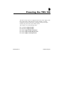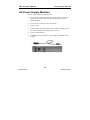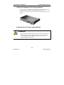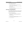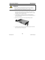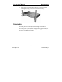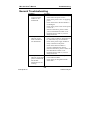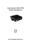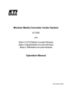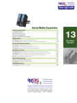
1
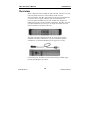
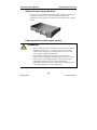
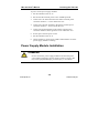
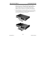
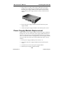
TRC-190 User’s Manual First Edition, November 2008 www.moxa.com/product © 2008 Moxa Inc. All rights reserved. Reproduction without permission is prohibited. www.ipc2u.ru www.moxa.pro TRC-190 User’s Manual The software described in this manual is furnished under a license agreement and may be used only in accordance with the terms of that agreement. Copyright Notice Copyright © 2008 Moxa Inc. All rights reserved. Reproduction without permission is prohibited. Trademarks MOXA is a registered trademark of Moxa Inc. All other trademarks or registered marks in this manual belong to their respective manufacturers. Disclaimer Information in this document is subject to change without notice and does not represent a commitment on the part of Moxa. Moxa provides this document “as is,” without warranty of any kind, either expressed or implied, including, but not limited to, its particular purpose. Moxa reserves the right to make improvements and/or changes to this manual, or to the products and/or the programs described in this manual, at any time. Information provided in this manual is intended to be accurate and reliable. However, Moxa assumes no responsibility for its use, or for any infringements on the rights of third parties that may result from its use. This product might include unintentional technical or typographical errors. Changes are periodically made to the information herein to correct such errors, and these changes are incorporated into new editions of the publication. www.ipc2u.ru www.moxa.pro Technical Support Contact Information www.moxa.com/support Moxa Americas: Toll-free: 1-888-669-2872 Tel: +1-714-528-6777 Fax: +1-714-528-6778 Moxa China (Shanghai office): Toll-free: 800-820-5036 Tel: +86-21-5258-9955 Fax: +86-10-6872-3958 Moxa Asia-Pacific: Moxa Europe: Tel: +49-89-3 70 03 99-0 Tel: +886-2-8919-1230 Fax: +49-89-3 70 03 99-99 Fax: +886-2-8919-1231 www.ipc2u.ru www.moxa.pro Table of Contents Chapter 1 Introduction .................................................................. 1-1 Overview...........................................................................................1-2 Package Checklist .............................................................................1-3 Product Specifications.......................................................................1-4 Chapter 2 Slide-in Modules........................................................... 2-1 Installing or Removing Chassis Face Plate .......................................2-2 Installing the Media Converter Slide-in Modules .............................2-3 Replacing the Media Converter Slide-in Modules ............................2-4 Chapter 3 Powering the TRC-190 ................................................. 3-1 AC Power Supply Modules...............................................................3-2 DC Power Supply Modules...............................................................3-4 Power Supply Module Installation....................................................3-6 Power Supply Module Replacement .................................................3-8 Power Supply Fuse Replacement......................................................3-9 Chapter 4 TRC-190 Rackmounting............................................... 4-1 Installing the TRC-190 Chassis.........................................................4-2 Grounding .........................................................................................4-4 Chapter 5 Troubleshooting ........................................................... 5-1 General Troubleshooting...................................................................5-2 www.ipc2u.ru www.moxa.pro 1 Chapter 1 Introduction This chapter covers the following topics: Overview Package Checklist Product Specifications www.ipc2u.ru www.moxa.pro TRC-190 User’s Manual Introduction Overview Moxa’s NRack System includes the TRC-190-XX, which is a 19-inch, rack-mountable chassis for selected Moxa media converter slide-in-modules. The TRC-190-XX allows the network administrator to connect various copper and fiber-optic network media over protocols that include RS-232, RS-422, and RS-485. Support for additional protocols will be available in the future. The TRC-190-XX provides installation space for up to 19 single-slot media converter slide-in modules in the front of the unit. The TRC-190-XX is equipped with an AC or DC power supply installed in the back of the chassis. An extra installation space is available for an optional redundant power supply (AC or DC). Last but not least, the TRC-190 also comes with a grounding lug to provide grounding for the chassis. www.ipc2u.ru 1-2 www.moxa.pro TRC-190 User’s Manual Introduction Package Checklist The Moxa TRC-190-xx series products are shipped with the following items: Standard Accessories • • • • • • TRC-190-xx with one AC or DC power supply in the back of the chassis 18 units of Chassis Face Plates and screws Rack Mount Kit Power Cord User Guide Warranty Card Optional Accessories • • PWR-190-AC PWR-190-DC Redundant AC Power Supply Module Redundant DC Power Supply Module NOTE: Notify your sales representative if any of the above items are missing or damaged. www.ipc2u.ru 1-3 www.moxa.pro TRC-190 User’s Manual Introduction Product Specifications Physic Characteristics Slots 19 slots in front for slide-in modules, 2 slots in back for power supply modules. Case SECC (1.2 mm) Dimensions 440 x 260 x 77 mm (18.6 x 11 x 3.3 inches) Gross Weight 5.2 kg or 11.4 lbs (with one power module inside) Environment Operating Temperature 0 to 60°C (32 to 140°F) Operating Humidity 5% – 95% RH Storage Temperature -40 to 85°C (-40 to 185°F) Power Requirement Input Voltage Universal 100 to 240 VAC 47-63 Hz or 12-48 VDC Max. Power 5.4A @ 12 VDC Consumption Regulatory Approvals CE Class B FCC Part 15 sub part B Class A EMI EN55022 1998, Class B EMS EN61000-4-2(ESD), Criteria A, Level 4 EN61000-4-3(RS), Criteria A, Level 2 EN61000-4-4(EFT), Criteria A, Level 3 EN61000-4-5(Surge), Criteria A, Level 3 EN61000-4-6(CS), Criteria A, Level 2 EN61000-4-8(PFMF), Criteria A, Level 3 www.ipc2u.ru 1-4 www.moxa.pro 2 Chapter 2 Slide-in Modules This chapter covers the following topics: Installing or Removing Chassis Face Plate Installing the Media Converter Slide-in Modules Replacing the Media Converter Slide-in Modules www.ipc2u.ru www.moxa.pro TRC-190 User’s Manual Slide-in Modules Installing or Removing Chassis Face Plate Install a chassis face plate over any unused slot by aligning the hole in the face plate with a threaded hole in the chassis. Secure the face plate with the enclosed screw. ATTENTION Each slot in the TRC-190-XX chassis without a slide-in module installed MUST have a chassis face plate covering the empty slot for Class A compliance. Remove the front plate by loosening the screw before installing any slide-in module. We suggest storing the removed face plates together in case you need to use them again. 2-2 www.ipc2u.ru www.moxa.pro TRC-190 User’s Manual Slide-in Modules Installing the Media Converter Slide-in Modules ATTENTION Wear a grounding device and observe electrostatic discharge precautions when installing or replacing the media converter slide-in modules into the chassis. Failure to observe this caution could result in damage to, and subsequent failure of, the media converter slide-in modules. Instructions to install the media converter slide-in module into the TRC-190 chassis are as follows: 1. Slide-in modules can be installed in any empty slot of the chassis in any order. 2. The media converter slide-in module can be hot-swapped, which means the chassis doesn’t have to power off during installation or when removing the module. 2-3 www.ipc2u.ru www.moxa.pro TRC-190 User’s Manual Slide-in Modules 3. Before installing the slide-in module, make sure the front plate has been removed. Please refer to the previous Installing or Removing Chassis Face Plate section. 4. Align the slide-in module with the chassis installation slot so that the panel fastener screw is at the top of the module. 5. Carefully slide the slide-in module into the slot while aligning the module’s circuit board with the installation guide. 6. Ensure the slide-in module is firmly seated inside the chassis. 7. Push in and rotate the attached panel fastener screw clockwise to secure the module to the chassis. 8. Repeat step 3 to 7 for any additional media converter slide-in module. Replacing the Media Converter Slide-in Modules To replace a media converter slide-in module in the TRC-190 chassis: 1. The media converter slide-in module can be hot-swapped, which means the chassis doesn’t have to power off during the installation or when removing the module. 2. Remove the slide-in module to be replaced by loosening the panel fastener screw that secures the module to the chassis. Slide the module out from the chassis. 3. Align the replacement slide-in module with the chassis installation slot so that the panel fastener screw is at the top of the module. 4. Carefully slide the slide-in module into the slot while aligning the module’s circuit board with the installation guide. 2-4 www.ipc2u.ru www.moxa.pro TRC-190 User’s Manual Slide-in Modules 5. Ensure the slide-in module is firmly seated inside the chassis. 6. Push in and rotate the attached panel fastener screw clockwise to secure the module to the chassis. 2-5 www.ipc2u.ru www.moxa.pro 3 Chapter 3 Powering the TRC-190 The TRC-190-AC chassis is equipped with an AC power supply in the back of the chassis. When the power supply module is correctly installed in the back of the chassis, powering on the power supply module will power on the whole TRC-190-AC. This chapter covers the following topics: www.ipc2u.ru AC Power Supply Modules DC Power Supply Modules Power Supply Module Installation Power Supply Module Replacement Power Supply Fuse Replacement www.moxa.pro TRC-190 User’s Manual Powering the TRC-190 AC Power Supply Modules The AC power supply module includes: • An AC power module that supports 110 to 220 VAC input and supplies power to the chassis and installed media converter slide-in modules. • An AC power connector with a fuse holder. • A power cord. • An ON/OFF switch, which allows the module to supply power to the chassis and slide-in modules when set to “I”. • A power LED indicator. • An additional fuse installed in a fuse holder on the PCB of the module. 3-2 www.ipc2u.ru www.moxa.pro TRC-190 User’s Manual Powering the TRC-190 Optional Redundant Power Supply Module An extra space is available at the right side of the back of the chassis to install an optional power module, the PWR-190-AC. The specification is the same as the one that comes with the TRC-190-AC chassis. Powering the AC Power Supply Module ATTENTION Ensure that the ON/OFF switch is set to “0” before connecting to the external power source. Failure to observe this caution could result in damage to, and subsequent failure of, the AC power supply module and human life. 3-3 www.ipc2u.ru www.moxa.pro TRC-190 User’s Manual Powering the TRC-190 To power on the power supply modules: 1. Set the ON/OFF switch to “0”. 2. Connect the female end of the power cord to the AC power connector on the power supply module. 3. Plug the male end on the power cord into the correct voltage AC rack or wall socket. 4. Set the ON/OFF switch to “l”. 5. Check whether or not the power LED is illuminated to see if the power supply module is working. DC Power Supply Modules The TRC-190-DC is equipped with a DC power supply in the back of the chassis. When the power supply module is correctly installed in the back of the chassis, powering on the power supply module will power on the whole TRC-190-AC. The DC power supply module includes: • A DC power module that supports 36 to 72 VDC input and supplies power to the chassis and installed media converter slide-in modules. • A DC power connector. • An ON/OFF switch, which allows the module to supply power to the chassis and slide-in modules when set to “I”. • A power LED indicator. 3-4 www.ipc2u.ru www.moxa.pro TRC-190 User’s Manual Powering the TRC-190 Optional Power Supply Modules An extra space is available at the right side of the back of the chassis to install an optional power module, the PWR-190-DC. The specification is the same as the one that comes with the TRC-190-DC chassis. Powering the DC power supply module ATTENTION • Before connecting to the external power source, ensure that the ON/OFF switch is set to “0”. Failure to observe this caution could result in damage to, and subsequent failure of, the DC power supply module and human life. • This product is intended to be used in a restricted access location. Proper grounding (earth ground) is required to ensure safe operation. A grounding terminal is provided for proper grounding of the device as per customer installation requirements and local electrical codes. Before installation, use a volt-meter/ohm-meter to check the wiring. 3-5 www.ipc2u.ru www.moxa.pro TRC-190 User’s Manual Powering the TRC-190 To power on the power supply modules: 1. Set the ON/OFF switch to “o”. 2. Be sure that the external power source is NOT powered. 3. Connect the +48 VDC terminal to the chassis external power connector marked “+”. Screw and fix the wire. 4. Connect the -48 VDC terminal to the chassis external power connector marked “-”. Screw and fix the wire. 5. Connect the ground terminal to the chassis external power connector marked “chassis ground”. Screw and fix the wire. 6. Power up the external power source. 7. Set the ON/OFF switch to “l” 8. Check whether or not the power LED is illuminated to see if the power supply module is working. Power Supply Module Installation ATTENTION Do not connect the power supply module to the external power source before installing it into the chassis. Failure to observe this may cause equipment damage, personal injury or even death. 3-6 www.ipc2u.ru www.moxa.pro TRC-190 User’s Manual Powering the TRC-190 1. Install the AC power supply module and DC power supply module the same way. The default power supply module will be at power module Slot A. We can install an additional power supply module in Slot B. You can install the power supply module or remove it from Slot A or Slot B in the same manner. 2. When installing a power supply module to Slot A or Slot B, be sure that the there is no plate installed in the specific slot. If there is, remove the plate first. To remove the plate, remove the 2 screws that secure the plate to the chassis. 3-7 www.ipc2u.ru www.moxa.pro TRC-190 User’s Manual Powering the TRC-190 3. Where there is no plate on the chassis, slide the power supply module slowly and follow the installation guide in the chassis. Push the power supply module into the chassis till the end and ensure that the power supply module is firmly connected to the chassis. 4. Screw the power supply module clockwise and fix the power supply module. 5. Connect the power supply module to the external power source. Power Supply Module Replacement Replace the AC power supply module or DC power supply module by the same way. Do not remove the power supply module from chassis when the power source is connected and the external power switch is set to “o”. When the chassis is equipped with 2 power supply modules, any one of them can be hot swap without making the other one stop worked. 1. Set the power supply module power switch to “o”. 2. Disconnect the power supply module from the external power source. 3. Loose the two screws on the power supply module. 4. Slide the power supply module smoothly. 3-8 www.ipc2u.ru www.moxa.pro TRC-190 User’s Manual Powering the TRC-190 5. Install another new power supply module following the instruction in the previous section. Power Supply Fuse Replacement Replace fuse on power supply module has no need to pull the power supply module out of chassis. Replacing the Fuse ATTENTION Wear a grounding device and observe electrostatic discharge precautions when replacing the fuse in the power supply module. Failure to observe this caution could result in damage to, and subsequent failure of, the power supply module. Follow the instructions below when you need to change the fuse: 1. Set the power switch on the power supply module to “o”. 2. Disconnect the power supply module from the external power source. 3. Remove the fuse from the holder carefully. 4. Install a same size and same rating fuse in the fuse holder. Note: Failure to use a fuse of same size and same rating may damage your power module or even the entire equipment setup. 5. Connect the power supply module to the external power source. 3-9 www.ipc2u.ru www.moxa.pro TRC-190 User’s Manual Powering the TRC-190 ATTENTION Do not connect the power supply module to the external power source before installing it into the chassis. Failure to observe this may cause the equipment damage, personal injury, or even death. 3-10 www.ipc2u.ru www.moxa.pro 4 Chapter 4 TRC-190 Rackmounting This chapter covers the following topics: Installing the TRC-190 Chassis Grounding www.ipc2u.ru www.moxa.pro TRC-190 User’s Manual Rackmounting Installing the TRC-190 Chassis The TRC-190 series can be installed in a standard 19-inch rack. NOTE: Rack-mounted equipment must be reliably grounded. Power supply connections other than direct connections to the branch circuit (e.g., use of power strips) should be employed. The TRC-190 series chassis is designed so that the installation brackets can be installed to align the chassis either flush against the front of the rack or recessed from the front of the rack. ATTENTION Select mounting bracket locations on the chassis that will keep the chassis balanced when mounted to the rack. Failure to observe this warning could allow the chassis to fall, resulting in equipment damage and/or possible injury to personnel. To install the TRC-190 chassis into a standard 19-inch rack: 1. Determine the preferred alignment of the chassis in the rack. NOTE: Installation bracket mounting screws are provided. Rack mount screws and clip nuts are NOT provided. 2. Locate four (4) installation bracket mounting screws (provided) for each chassis to be installed. 4-2 www.ipc2u.ru www.moxa.pro TRC-190 User’s Manual Rackmounting ATTENTION Mount the chassis evenly and securely onto the rack. Failure to observe this warning could allow the chassis to fall, resulting in equipment damage and/or possible injury to personnel. 3. Align the mounting bracket in the selected position against the side of the chassis so that the chassis installation holes are visible through the bracket installation holes. 4. Using a Phillips (crosshead) screwdriver, install the four (4) screws through the mounting bracket into the installation holes on the side of the chassis. 5. Repeat step 3 and step 4 for the second mounting bracket. 6. Carefully align the chassis at a secure and level position between the 19-inch site rack mounting rails. 4-3 www.ipc2u.ru www.moxa.pro TRC-190 User’s Manual Rackmounting 7. Install two (2) screws through the bracket at each side into the mounting rail, using the clip nuts to secure, if necessary. Grounding Grounding and wire routing help limit the effects of noise due to electromagnetic interference (EMI). Run the ground connection from the ground screw to the grounding surface prior to connecting devices. Attach the grounding wire (12 AWG copper wire gauge or larger) to the chassis grounding lug carefully. 4-4 www.ipc2u.ru www.moxa.pro 5 Chapter 5 Troubleshooting This chapter covers the following topics: General Troubleshooting www.ipc2u.ru www.moxa.pro TRC-190 User’s Manual Troubleshooting General Troubleshooting Condition 1. The LED indicator on power supply module is not illuminated. 2. 3. Try this • Check if the Power Cord is correctly connected to the power source. • Check if the power source is supplying power. • Check if the fuse in the fuse holder is not damaged. • Check if the power switch on the panel is set to “l” • If none of the above, please contact your local distributor/reseller or our technical support staff. Or, write to [email protected]. The power LED • Check if the LED indicator on the indicator on the power supply module is illuminated. If slide-in module is no, follow the steps for Condition 1. not illuminated. • Check if the power supply module is really connected to the panel. • Check if the slide-in module is correctly attached to the chassis. • If none of the above, please contact our local distributor/reseller or our technical support staff. Or, write to [email protected]. The power LED • Check if the cables is correctly attach indicator on the front to the slide-in module. panel is illuminated, • Check if the pin-assignment of the but the data serial cable transmission is not working. 5-2 www.ipc2u.ru www.moxa.pro TRC-190 User’s Manual Troubleshooting • Check if the OP_Mode switch on the front panel is correctly set for your operation. • Check if the fiber patch cord is not damaged. • Check if the length of the fiber cable is under our claimed distance. • If none of above, please contact our local distributor/reseller or our technical support staff. Or, write to [email protected]. 5-3 www.ipc2u.ru www.moxa.pro