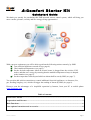
1
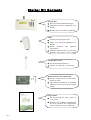
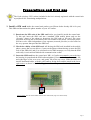
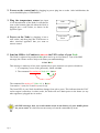
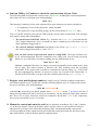
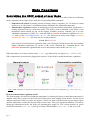
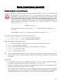
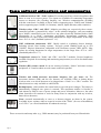
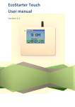
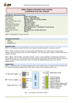
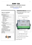
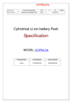
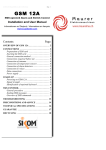
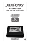
R
A -Comfort Starter Kit
Quickstart Guide
We thank you warmly for purchasing this SMS-operated remote control system, which will bring you
more comfort, pleasure, security and new energy saving opportunities!
With your new equipment, you will be able to perform the following actions remotely, by SMS:
!
! Turn electrical appliances on and off (see page 4).
!
! Check ambient temperatures (see page 5).
!
! Set the desired temperature when an electric heater is plugged into the wireless 230V
socket, and thus save energy by ensuring that the ambient temperature always is adapted
to the situation (see page 6).
!
Set
the temperature limits beyond which an alarm shall be sent by SMS (see page 7).
!
You can also add wireless extensions to control additional electrical appliances, or detectors (fire,
gas, flooding, burglary, etc.) which will trigger the sending of alarms by SMS (see page 8).
Discover soon the advantages of a simplified operation by Internet, from your PC or mobile phone
www.EcoStarter.com
Table of contents:
Starter Kit Contents .................................................................................................................................... 2
Preparations and first use ........................................................................................................................... 3
Main Functions ............................................................................................................................................ 6
Some optional extensions and accessories ................................................................................................. 8
© 2011, EcoStarter
Page 1
Starter Kit Contents
Central unit
••
••
Receives and sends SMS messages.
••
Handles up to 64 wireless peripherals.
Manages all wireless peripherals (e.g.
Nodes).
‘Node’
••
••
Wireless 230V plug-in socket.
••
Reads, monitors
temperatures.
••
Transmits alarms from any connected
detectors and sensors to the central
unit.
Turns your electrical appliances on
and off.
and
regulates
Temperature sensor
••
••
For measuring temperatures.
Connect it to input #1 of your Node.
Wall bracket for the central unit
••
Fix the central unit to the wall where
and if you want.
••
The central unit shall not be mounted
inside the fuse box (or any other metal
locker).
User manual
Page 2
••
For discovering the finer points of
your system.
••
Reference for all SMS commands and
for local operation and configuration
via the input panel of the central unit.
Preparations and first use
The Node (wireless 230V socket) included in the kit is already registered with the central unit
as peripheral #01. Remaining manipulations:
1. Install a SIM card inside the central unit (unless your Sikom dealer already did it for you).
This SIM card determines the phone number of your A-Comfort.
1.1. Deactivate the PIN code of the SIM card before you install it inside the central unit.
To this end, insert the SIM card into a standard GSM mobile phone and use the
“Security” menu of the phone to deactivate the PIN code of the card. The exact
procedure for doing this is described in the user manual of the phone. The mobile phone
will have to be either independent of any operator (network provider) or else locked to
the very operator that provided the SIM card.
1.2. Check the validity of the SIM card: still having the SIM card installed in the mobile
phone, ensure that you are able to (1) turn on the phone without having to enter the PIN
code of the SIM card, and (2) to send and receive SMS messages, to verify that the SIM
card really is activated and loaded with communication credits.
1.3. Insert the SIM card into the central unit. NB! A-Comfort must not be powered when
the housing is opened and the SIM card manipulated. Unscrew the 2 screws near the left
and right edges of the rear cover, and gently lift off the top cover. Slide the SIM card
into the dedicated holder, with the gold contacts facing down and the notch in the lower
right corner, as shown in the following picture. Put the top cover back and screw it on.
SIM
CARD
Above figure: how to insert a SIM card into the central unit (top cover unscrewed).
Page 3
2. Power on the central unit by plugging its power plug into a socket. After initialization, the
screen should display « GSM Online ».
3. Plug the temperature sensor into input
#1 on the underside of the Node. It will then be
seen on the bottom right side when the Node is
plugged into a wall socket, as shown in the
opposite figure.
4. Power on the Node by plugging it into a
wall socket, and then plug into it the heater or
other electrical appliance that you want to
remote control.
Node
Front LED
Temperature
sensor
5. Send an SMS to A-Comfort to turn on the 230V socket of your Node.
The Node is registered as peripheral #01 (there can be up to 64 of them!). Text of the SMS
message (the colours are here only to facilitate your understanding):
1234 R011
This message is made up of two parts separated by a space character (no spaces elsewhere):
1. A compulsory access code (password), which is 1234
2. The command for turning on Node #01 : R011
The command for turning off Node #01 is R010
Convention: 1 (one) for on and 0 (zero) for off.
The front LED of your Node should then change from red to green. This indicates that the 230V
socket output is turned on; in other words, the Node will now admit power to the heater (or any
other appliance) plugged into its socket.
All SMS messages that you send remain stored in the history of your mobile phone
for you to reuse. It is therefore not necessary to learn the commands by heart!
Page 4
6. Send an SMS to A-Comfort to check the current status of your Node.
The following SMS will return the current status of Node #01, including the current temperature
(the colours are here to facilitate your understanding):
1234 S01
This message is made up of two parts separated by a space character (no spaces elsewhere):
1. A compulsory access code (password), which is 1234
2. The request for a reply by SMS giving you the current status of Node #01: S01
Your A-Comfort will then send you an SMS with the current status of that Node. This message
will contain, among other information:
•
The on/off state of the 230V socket. E.g., from the text « Out.On », you learn that the
230V output (shortened « Out ») is turned on; hence it admits power to the heater (or any
other appliance) plugged into it.
•
The current ambient temperature measured by the Node, e.g. « Input 1.+22c »
(the sensor plugged into input #1 reads +22°C).
You can turn on and request the new status in a single SMS. The reply will then serve
as an acknowledgement that the commands have really been received and processed.
Moreover, you will make a saving by sending just one SMS instead of two:
1234 R011 S01
Multiple commands like these are simply executed sequentially in the textual order, from
left to right. The status returned is therefore the state resulting from the preceding
commands. If the central unit is unable to communicate with the Node (e.g., if the Node
has been unplugged by mistake, or moved to a place out of reach of the central unit, i.e.
outside of the local radio coverage), then the returned status will say « No answer ».
7. Register your mobile phone number to enable your A-Comfort to address temperature
surveillance alarms to you. To this end, send the following SMS to your A-Comfort (the colours
are here to facilitate your understanding):
1234 N10791234567#
Command N1 stores the given phone number (here: 0791234567) at the 1st position in the list of
alarm message addressees (there can be up to 9 numbers). Do not forget the final sharp character
(#). There are no space characters inside the command. Recall that 1234 is the compulsory
access code (password) of your A-Comfort.
8. Mount the central unit onto the wall (this is optional) according to Fig. 2 and 3, chapter
1.3 of the user manual. Choose preferably a place near the centre of your premises in order to
maximize the coverage of the local radio frequency (RF) communication that connects the
wireless peripherals to the central unit. Do not install the central unit inside the fuse box or any
other metal locker, as this will block the RF communication!
Page 5
Main Functions
Controlling the 230V output of your Node
The 230V output (called «Out» in status messages) of a Node is always in either of the two following
modes, illustrated in the figure below with the corresponding SMS commands:
• Manual on/off control for turning on and off lamps, pumps, computers, etc. If a heater is turned
on this way, it’s the heater’s own thermostat that determines the scheduled temperature.
• Thermostatic regulation consists in managing precisely the ambient temperature produced by a
heating appliance such as a convector heater. The Node is then a substitute to the heater’s own
thermostat (which should be left on the highest available position), enabling you to set the
scheduled temperature by SMS. E.g., send this SMS to activate thermostatic regulation on Node
#01 with a lower « eco-temperature » at +6°C (for when you are away) and a higher « comfort
temperature » at +20°C (for when you are on the premises):
1234 L011+06+20
Once a Node is in thermostatic regulation mode, you will simply switch between the lower and the
higher scheduled temperature by means of the on/off command R. Command L010 will
deactivate thermostatic regulation and revert to the manual control mode (on Node #01).
NB: temperatures are always written with a ‘+’ or ‘-’ sign followed by two digits (e.g., +06 for +6°C).
NB: a temperature sensor must be plugged into input #1 of the Node to enable thermostatic regulation.
Manual control
Thermostatic regulation
Above: SMS commands for manual on/off and for switching between comfort/eco temperatures (e.g. +20°C resp. +6°C).
How does thermostatic regulation work?
The Node arranges for the desired ambient temperature by turning the heater on until that temperature is
attained. When this is achieved, the Node cuts off the power, thus turning off the heater. As soon as the
ambient temperature falls by at least one degree Celsius, the Node will admit power to the heater again,
until the temperature reaches the desired value on more time. This cycle repeats ad infinitum. Concretely,
during this automated activity, the Node will spontaneously toggle its 230V socket between on (green
front LED and status « Out.On ») and off (red front LED and status « Out.Off ») and vice-versa.
Page 6
Main Functions (cont’d)
Temperature surveillance
By means of command S01 (requesting the status by SMS), you may at any moment read
the temperature measured by your Node (#01). But you can also assign to it the task of
monitoring the temperature for you. This means that it will send you a notification by SMS
if the ambient temperature exceeds either of the lower or upper limits chosen by you. This is
a security mechanism, which may also be used in parallel to thermostatic regulation in order
to protect against a malfunction of the heating device. The following SMS command will
activate temperature surveillance on your Node (#01), with a lower limit at +4°C and an
upper limit at +22°C:
1234 T011+04+22
NB: temperatures are always written with a ‘+’ or ‘-’ sign followed by two digits (e.g., +06
for +6°C).
Command T010 will deactivate temperature surveillance on that Node (#01).
Temperature alarms by SMS take one of the following forms:
• 01 Alarm. Name 1.TempLo (the lower limit is attained), or
•
01 Alarm. Name 1.TempHi (the upper limit is attained).
Detailed explanation of message contents:
• 01: relevant Node number; this tells you where (in which room) the issue occurred.
•
Alarm: an alarm has been triggered.
•
Name: name of the Node (cf. user manual for giving a name to your Node).
•
TempLo: low temperature alarm.
•
TempHi: high temperature alarm.
NB:
Once a temperature alarm has been sent off, temperature surveillance is automatically deactivated.
As soon as the cause of the temperature issue has been corrected, remember to reactivate the
surveillance.
Prerequisites:
•
A temperature sensor must be plugged into input #1 of the Node to enable temperature
surveillance. Temperature limits must be in the range from -29°C to +49°C.
•
You have to register the phone number(s) to which temperature alarms are to be addressed. Please
refer to the preparations on page 5 of this document.
•
The « master alarm » switch must be active to enable the sending of temperature alarms by SMS.
It is in principle always active and must only be temporarily deactivated during the installation of
additional detectors such as fire, burglary, etc. Please refer to the user manual for the details.
Page 7
Some optional extensions and accessories
Additional wireless 230V ‘Node’ sockets. For turning on/off any electrical appliance that
starts as soon as it receives power. Two inputs are available for connecting temperature
sensors or detectors (fire, flooding, burglary, etc). Wireless communication (433MHz)
with the central unit. Available as Swiss socket (supporting up to 2300W) and “Schuko”
socket (supporting up to 3600W, for Germany, Austria, Spain and many other countries).
Wireless relays ‘GR-1’ and ‘GR-3’. Modules providing one, respectively three remotecontrolled switches (“potential-free relays” in the technical language), each one standing
up to 3600W, centralized in your fuse-box or any other electrically insulated locker. Same
functionality as a “Node”: temperature surveillance, thermostatic regulation, alarm
transmission, etc. May replace an existing thermostat for target temperatures in the range
from -29°C to +49°C (standard hystheresis: 1°C).
230V wall-mount thermostats ‘SI-2’. Ideally suited to regulating electric heatings,
including electric floor heating systems. Two-pole switch standing loads up to 16A
(3600W). Physical dimensions compatible with 50x50mm systems (DIN 49075). May
replace an existing thermostat for target temperatures in the range from -29°C to +49°C
(standard hystheresis: 1°C).
Temperature sensors for ‘Nodes’ and ‘GR-1’ and ‘GR-3’ modules. Various lengths are
available. Required for measuring and monitoring temperatures, as well as for thermostatic
regulation.
Wireless (RF) remote control for on-site steering of alarms, “Nodes” and other wireless
peripherals. A-Comfort admits several remote controls in parallel.
Wireless and cabled detectors: movement, burglary, fire, gas, water, etc. The
movement detector (PIR) and the fire detector are available either as battery-driven
wireless units, or as wired detectors to be plugged into a “Node” or a “GR-1” module. The
other detectors are only available as cabled items.
Backup battery, which enables the central unit to cope with power outages. The battery is
automatically recharged once power is restored. This equipment enables A-Comfort to
emit alarms by SMS in case of power outage and power restoration. Moreover, the other
alarm functions will continue to work for many hours in conjunction with any wireless,
batter-driven detectors.
Siren: resounds automatically as soon as a detector triggers an alarm in the system.
Available in two variants: either as a special version of the “Node” (for ease of installation)
or of “GR-1” (as a fixed installation for enhanced security).
These accessories and many other (e.g., GSM antennas) may be purchased from your Sikom dealer.
Page 8