1
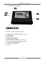
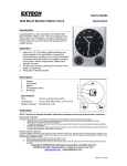
MICROPROCESSOR
TEMPERATURE CONTROLLER
24
SERVICE MANUAL
WARRANTY CARD
2
SP 24 Manual
1.
Front panel description
10
2
1
3
4
5
6
7
8
9
Controller view with marked functions
1.
2.
3.
4.
5.
6.
7.
8.
9.
10.
Turning on (hold ENTER button for 2 sec.).
LCD display.
Indicator lights.
Device control buttons.
Airflow start up indicator.
Central heating pump start up indicator.
Hot service water pump start up indicator.
Floor pump start up indicator.
Loader start up indicator.
7A fuse.
3
SP 24 Manual
2. Application
Controller is equipped with innovative, intelligent Logic control system.
This system consists in automatic adjustment of boiler power to current
operating conditions. All regulation process is based on measurement of
central heating temperature. Due to innovative solution enabling optimal
fuel combustion in the boiler, it has the effect of reduction of harmful oxides
emission into the atmosphere. With proper oxides aftercombustion and no
overshoots , boiler equipped with our device can use up to 30% less fuel
than standard solutions.
3. Controller operation
To start up the controller hold ENTER button. After controller start up, main
page with following information is displayed on LCD:
Central heating (CH) temperatures - current and
set up
Hot service water (HSW) temperatures - current
and set
0
0
CH 22 C z 55 C
0
0
HSV 22 C z 45 C
From the main page you have the access to several functions, pressing ( )
enters into central heating temperature adjusting mode, you set up desired
temperature with ( ) and ( ). When temperature decreases below 35oC (--)
and ENTER button is pressed, central heating pump turns off. Controller
enters SUMMER MODE, with only hot service water function.
However, if ( ) is pressed as first, you enter into setting up hot service water
temperature. By pressing ( ) and ( ) you set up desired temperature.
When temperature decreases below 35oC (--) and ENTER button is
pressed, hot service water pump turns off.
Caution!!!
If installation is not equipped wit hot service water pump you should
turn off water heating function.
Pressing ENTER button confirms selected parameter and pressing EXIT
button exits without saving previously made changes.
CH Temperature
Blower power
0
59 C
BLOWER POW. 30%
4
SP 24 Manual
FUNCTIONS
- MANUAL OPERATION function is to fire up the
boiler, it enables independent start up of
controller
Manual operation
Blower
Pressing ENTER button turns on one of the outputs. With ( ) and ( ) you
change output to be turned on or off. Pressing EXIT returns to set up
menu.
- HSW hysteresis that function is to set up service
water hysteresis, it consists in delaying HSW
pump start up by set up number of degrees, i.e.
hystheresis 2o, set up temperature 50oC - pump
shall start up when service water temperature
decreases to 48oC. This function works in HSW
priority and summer mode.
- CH/HSW PRIORITY
- HSW PRIORITY HSW pump starts up and works
until achieves set up temperature. When services
water reaches set up temperature HSW pump
turns off and CH pump turns on.
HSW hysteresis
Hysteresis temp.
HSW
20C
CH/HSW Prority
HSW Prority
- CH PRIORITY in this mode pumps start working CH Prority
when boiler temperature reaches temperature set
up in pump start up function. (CH pump works
permanently and HSW pump turns on after reaching desired temperature.)
In this mode HSW temperature cannot be higher than CH temperature.
- FUEL TYPE function allows to select previously
FUEL TYPE
adjusted fuel, i.e.: (different calorific value of fuel). FUEL 1
Controller is possible to adjust and save four
various fuel configurations. More information on adjusting loaded fuel in
further part of the manual.
5
SP 24 Manual
- FLOOR HEATING
Floor heating
Controller is equipped with input supplying the
floor pump and temperature sensor which is
installed on recycle of floor installation. Floor
FLOOR TEMP
220C z 350C
installation also requires installation of tee valve
on boiler output in order to limit temperature of
installation supply. This function ensures readout and maintaining constant
temperature of floor installation. Turning off the function is performed the
same as for other pumps (you should go below minimum temperature and
then two horizontal lines shall appear on the screen, confirmation with
ENTER button). To start the function again set desired temperature and
press the ENTER button.
- MANUFACTURER SETTINGS controller is
equipped with programmed settings, you may
return to them at any time. However, you should
remember that all personal settings will be lost.
- END OF WORK turns the controller off. To turn
it on again press and hold ENTER button
MANUF. SETTINGS
MANUF. SETTINGS
YES
END OF WORK
END OF WORK
YES
Controller has got hidden installation menu, to get there press and hold
( ) and ( ) buttons for 3 seconds. Changes of parameters in that menu
should be made by qualified person. Unauthorized changes of those
parameters may cause controller misoperation.
INSTALLATION MENU
- TURN OFF TIME function is to set time which is
measured when CH temperature does not
increase and maintains 5oC below set
temperature.
TURN OFF TIME
TURN OFF TIME
60 min
6
SP 24 Manual
- MAINTENANCE PAUSE function enables setting
up break time between blower and loader start u
in maintenance mode.
MAINTENANCE PAUS
MAINTENANCE PAUS
15 MIN
- MAINTENANCE OPERATION function allows
setting up time of blower and loader operation in
maintenance mode.
MAINTENANCE WORK
MAINTENANCE WORK
30 SEK.
- BLOWER START-UP this function consists in
BLOWER START UP
setting 100% power of blower with time
parameter (1sec. - 15 sec.) which, due to
temporary loss of efficiency, has to be regulated. BLOWER START UP
1.0 sek.
When you notice that the blower does not work
correctly during start (it cannot start) you should increase start-up time.
- ROOM REGULATOR room regulator may be
connected to the controller. It controls CH
circulation pump. Two-core cable is led out from
room regulator that should be connected to jack
input. No external power sources should be
connected to the device during installation of
room regulator. When function is turned on, an
arrow should appear on the display (upper right
area). If room regulator is not connected to the
device this function should not be turned on.
- FLUE GAS TEMPERATURE (option) there is
possibility of chimney sensor installation.
Function allows to set up maximum threshold of
flue gas temperature.
- WORM TEMPERATURE this unction protects
against fuel ignition in boiler basket. When
temperature of the worm increases above set up
temperature, loader will start giving the fuel for
10 min. in order not to allow the fuel to ignite in
boiler basket.
ROOM REGULATOR
ROOM REGULATO
ON
0
0
CH 22 C z 55 C
0
0
HSV 22 C z 45 C
MAX. FLUE GAS TEMP
250 0C
WORM TEMPERATURE
MAX. WORM TEMP
600C
7
SP 24 Manual
ADJUSTING THE AMOUNT OF LOADED FUEL
They are two tests, test of minimum and maximum power. Proper
setting of those two parameters guarantees efficient operation of the
boiler. Test should be carried out for each fuel you intend to use, fuel
change requires carrying out new test. Change of minimum power of
the blower will cause change of minimum power for each fuel
(1,2,3,4). Improper adjustment of the fuel may result in retort loader
damage.
- MIN. BLOWER POWER function is to set up
minimum fan power. Fan should be set up to
work at minimum power. However, you should
remember that fans lose their factory parameters
as a result of use and soil. In that situation you
should increase minimal airflow power.
MIN. BLOWER POW.
FUEL 1
MIN. BLOWER POW.
12%
CAUTION!!!
change of this parameter requires new adjustment of amount of
loaded fuel, test of minimum power for each fuel type (1,2,3,4).
- FUEL 1 - Adjustment of amount of loaded fuel.
FOEL 1
MAX. BLOWER POW.
- MAX. BLOWER POWER - this function is to limit MAX. BLOWER
maximum airflow power. Maximum power should
be limited when used fuel (pellet, oat) is too light
and is blown around in combustion chamber due to huge fan
power.
- FUEL LOAD this function is for quick correction
of amount of loaded fuel for minimum an
maximum power.
FUEL LOAD
4%
POW.
99 %
43%
- MINIMUM POWER TEST function consists in
MIN. POWER TEST
adjusting the amount of loaded fuel in relation to
210C
3%
minimum amount of loaded air forced to the
furnace by the blower. During test your task is to
set up fuel dose in a way that fuel feeding shoul be directly proportional to
combustion. Recommended time of minimum power test is 4 to 5 hrs.
Confirmation of parameter causes saving set up parameter in FUEL
TYPE menu.
8
SP 24 Manual
- MAXIMUM POWER TEST function consists in
MAX. POWER TEST
adjusting the amount of loaded fuel in relation to 210C
43%
maximum amount of loaded air forced to the
furnace by the blower. During test your task is to set up maximum fuel
dose in a way that fuel feeding should be directly proportional to combustion.
At the moment of carrying out the test boiler operates with maximum power.
During test the controller monitors CH temperature. In case of exceeding
80oC controller terminates the test and enters into operation mode.
Confirmation of parameter causes saving set up parameter in FUEL TYPE
menu.
CAUTION!!!
Electronics company does not bear any responsibilities for improper.
4. Technical data
1.
2.
3.
4.
5.
6.
7.
8.
9.
10.
o
o
CH temperature adjustment range 35 C - 80 C.
o
o
HSW temperature adjustment range 35 C - 65 C.
o
o
HSW floor adjustment range 20 C - 55 C.
Automatic blower adjustment.
o
o
Operation in ambient temperature 0 C - 40 C.
Automatic saving of settings during supply voltage decay.
Relative air humidity 95%.
I insulation class.
7 A fuse.
Controller has got function preventing from premature freezing of
installation, in case oftemperature decrease below 6oC circulation pump
starts up automatically.
11. Controller is equipped with secondary protection (emergency
thermostat) which protects the boiler against overheating.
5. Use
1. Connect feeder of CH and HSW pump.
a) yellow-green conductor to earth terminal,
b) blue conductor to "N" terminal,
c) brown conductor to "L" terminal.
2. After connecting the blower, pumps and after installing all sensors turn the
controller on. After performing above actions the controller ensures:
a) maintaining constant temperature of CH boiler set up by user.
b) automatic start of pumps and blower.
c) automatic shutdown of the blower and pumps after fuel use up.
d) continuous readout of temperatures.
9
SP 24 Manual
6. Error messages
Error 0 - Device failure.
Error 1 - EEPROM memory failure.
Error 2 - CH temperature sensor failure.
Error 3 - HSW temperature sensor failure.
Error 5 - Floor pump sensor failure.
Error 6 - Too high CH temperature.
Error 8 - Too high HSW temperature.
Error 9 - No fuel.
7. Fuse replacement
To replace the fuse disconnect the feeder from the socket.
8. Installation recommendations
1. Controller installation should be entrusted to authorized person.
2. Controller should be placed in location disabling it becoming heated
above 40oC.
3. Perform installation in accordance with par. 5 (Use)
4. Device should be installed and operated in accordance with rules of
operating electrical devices. Controller must not be exposed to water or
to conditions causing steam condensation i.e. rapid changes of ambient
temperature.
5. In cases of controller misoperation first check:
a) the fuse
b) connections stability and technical condition of cooperating devices,
that means the blower, pumps.
c) Set the controller to manufacturer settings.
6 Boiler should have check valves installed in cycles of CH and HSW pumps.
7. Floor installation requires installation of tee valve on boiler output in order.
CAUTION!!!
Perform connecting blower and circulation pumps motors only after
disconnection of the controller from 230V supply network.
9. Electric parameters
1. Supply voltage
2. Power consumption (no ratings)
3. Output ratings:
blower
loader
pumps
CH
HSW
floor
~ 230 V / 50 Hz
2W
100 W
250 W
100 W
100 W
100 W
10
Warranty card
10. Warranty card
1. Manufacturer guarantees good quality of equipment, guarantee and
post-guarantee services.
2. Manufacturer grants the guarantee of failure-free controller operation
for the period of 24 month from purchase date.
3. Failures and damages revealed during warranty period shall be
eliminated immediately, free of charge within not longer than 14 days
from the day of delivering the device for repair at manufacturer location.
4. Shipment costs are incurred by the customer.
5. When making a complaint failure description should be attached.
6. Warranty does not include damages arose due to improper operation
by the user or modifications and repairs performed not by service centre.
7. Seller is obliged to fill in the warranty card on the day of giving out the
equipment. Warranty card which is not filled in or having any corrections
or cross outs precludes exercising warranty rights.
Information on utilization of electric and electronic devices
This symbol placed on products or documentation attached to them informs
that unserviceable electric or electronic devices must not be thrown away
together with garbage. Proper behaviour in case of necessity of utilization,
reuse or components recovery consists in handing over the device to
specialized collection point where you shall not be charged. Proper utilization
of the device enables preservation of valuable resources and avoidance of
negative effect to the health and environment. Detailed information about the
nearest collection point may be obtained from your local authorities.
11
Producent:
Zak³ad Elektroniczny „Electronics”
Tadeusz Wilgocki
ul. Moczyd³o 10a, 30-698 Kraków
tel. 012 650 47 90, fax 012 650 47 91
e-mail: [email protected]