1
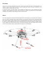
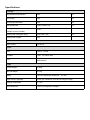
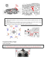
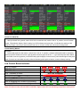
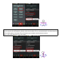
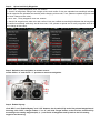
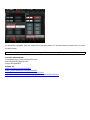
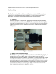
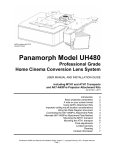
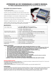
Hawk F900
User Manual V1.0
2014.09
Disclaimer
Thank you for purchasing SkyhawkRC this product. Please visit the Hawk F900 page on www.SkyhawkRC.com
regularly to keep up with product information, technical updates and manual corrections, information in this
manual is subject to change without any notice.
In using this product, you hereby agree to this disclaimer and signify that you have understood all points
completely. When assembling this product, follow all instructions carefully. The manufacturer and seller assume
no liability for any damage or injury arising from the use of this product.
About
The F900 is designed for professional aerial photography and cinematography. It is user friendly, safe, stabilized,
easy to fly while its integrated design makes assembly and configuration simple and fast. Retractable landing
gear, vibration dampers, slightly angled arms and a minimalized gimbal mount allow for a 360 degree view from
the camera. A power distribution board, built-in high-speed ESCs and motors with efficiency propellers ensure
dynamic stability and maximized power efficiency. Used with a professional multi-rotor autopilot system, the F900
can hover and fly reliably making it ideal for aerial photography and cinematography.
Contents
Disclaimer
About
Contents
Cautions
Specifications
In the box
Mounting landing gear
Mounting fuselage
Preparations before flight
LED control board indicator
Magnetic compass calibration
Auto Navigation calibration
ESC sound
ESC LED
Specifications
Gain value setting (with x4 flight controller)
FAQ
Soldering ESC
Remounting the propeller
Propeller precaution
Using the propeller holder
Assembling motor vibration absorbers
Remounting landing gear servo
Recalibrating servo traval
Part list
The FCC Certificate requirements
Cautions
When flying, fast rotating propellers may cause serious damage and injury. Please fly safe at all times.
Assembly Cautions
(1) Mount the GPS module with a bracket, to avoid interference with the power board on the center frame.
(2) Ensure “▲” sign is mounted with the arrow pointing toward the front.
(3) Please keep antenna of receiver unfold and down with no obstructions, keep antenna of image transmission
far away from receiver to avoid signal blocking or interfered and lose control.
facing downwards away from obstructions to avoid loss of control due to signal loss.
(4) Ensure fuselage and landing gear are mounted correctly.
(5) Do not remove any glued-in screws.
(6) Tighten screws appropriately. Screws can be used without thread locker once. On other occasions, apply
appropriate thread locker.
(7) F900 should be raised above the ground when testing landing gear or re-calibrating servo travel.
(8) Notice that matching the indicators is very important. Please pay attention to them.
(9) Fuselage moving parts are marked as red and safety sign, while holding these parts, please note their
moving scope to avoid injury...
(10). Please do not tear installed screws down to avoid fuselage loose or damage.
(11). Please do not change installation place and direction of fuselage, it will affect aircraft’s normal working.
Flight Cautions
(1) ESCs are not water-proof, do not fly in rain or snow.
(2) Ensure all parts are in good condition before each flight. Do not fly with worn or broken parts.
(3) Ensure propellers and motors are installed correctly before flying.
(4) Ensure ESC signal connectors and power cable connectors are tight and reliable before every flight.
(5) When flying, stay away a safe distance from people, buildings, high-voltage lines, tall trees, water and
other hazards.
(6) Use only 6S LiPo batteries for the power supply.
(7) Ensure all output signals from M1 to M8 are in proper working order when using the original flight control
system to avoid damage or injury.
(8) Do not overload the system.
(9) Do not get close to or touch motors or propellers when they are spinning as this can cause serious injury.
(10) Disconnect battery and remove camera during breaks and transportation to avoid damage or injury.
(11) We strongly recommend using as X-VIKI manufactured parts as possible.
(12) Check if the switch and joysticks of remote control are in right position, user must turn on remote control
firstly before flight.
(13) Make sure battery in sufficient power before flight, otherwise, replace a new battery.
(14) Please do not take off until GPS 7 satellites (red LED indicator disappears).
(15) Open GCS and real-time monitor working state.
Others
If you have any problem you cannot resolve, contact your dealer or SkyhawkRC customer service.
Specifications
Fuselage
Diagonal Motor Wheelbase
920
mm
Arm Length
422
mm
Center Board Diameter
230
mm
Max Spread Size
1260 x 1260 x 535
mm
Fuselage Weight(motors, ESC, propellers
2720
and flight control included)
g
Landing Gear Size(gear down)
348 x 400 x 350
mm
Landing Gear Weight
630
g
System
Flight Control
YS-X4 V2
Power
Motor
C3510
KV580
Propeller
1355
ESC
3~6S 25A, refresh rate 30~450Hz, driver frequency
8KHz/24KHz
3K carbon fiber
Flight
Aircraft Weight
3.35Kg
Take Off Weight
≤7.7Kg
Battery
LiPo 6S 10000mAh~20000mAh
Flight Time(no payload)
31min (6S 15000mAh LiPo take off weight 5.05Kg)
Working Temperature
5~40℃
Wind Resistance
<5.4m/s (6.5Kg take off weight)
10~25C
In The Box
Fuselage x1
Landing Skid Top Board
Landing Skid Tube x2
Landing Skid Leg x2
Accessories Bag x1
Screw Bag
WIFI Antenna x1
Tools Bag x1
Propellers(3K carbon fiber 13inch) x8
Remote Control(WFT09) x1
Battery(6S 22.2V 15,000mAh) x1
Charger(B6) x1
Mounting Landing Gear
Instructions
1. Slide landing gear leg into landing skid tube then affix the joints with M3x16mm and M3x22mm screws.
2. Insert the landing gear leg into connection point on the top board. Affix in place with M3x8 screws.
3. Please check the landing skid manually until it can be retracted by hands smoothly.
Mounting Fuselage
Instructions:
1. Hold the center board, unfold the arms one by one, the arms will be locked automatically while in right
location. Please pay attention to their movement scope to avoid clipping fingers.
2. Hawk F900 adopts “X” type structure, the front is two red motor base. To put fuselage on landing gear
horizontally and insert quick release key and turn 90 degree in clockwise, it will be locked automatically.
3. Unfold GPS support and twist nut to make antenna no waggle, check the “▲” sign on GPS antenna and
make it point to the front, not deflective, otherwise, it will affect its performance while hovering.
4. Insert reinforced screws on center board to make arms locked better.
Instructions:
5. Please install propellers to motors according to numbers between propellers and arms. M1 and
M2 is the front.
6. Check rotating direction of propellers, from the upper of fuselage, M1, M3, M5 and M7 rotate in
anticlockwise direction and M2, M4, M6 and M8 rotate in clockwise direction.
7. Install battery on battery board and tie up with straps, bottom two XT60 ports are for aircraft.
Preparations Before Flight
Check Landing Gear
Instruction:
1. Control gear up/down by channel 9 on remote control, besides, user also can control it by hand while power
cut down. No matter what position of channel 9 switch located, the gear is on down state while power is on.
Working State
CH9
Gear Down
2
Gear Up
0
Install GCS software
Instruction:
2. Install CCS software on android mobile or tablet(we will send user GCS software after purchase done)
Check remote control settings on GCS software
Instruction:
3. Turn on remote control, CH5 and CH6 switch to “0” position, CH9 switches to “2” position, cut down ESC
power and connect flight control power, open WIFI on Android mobile or tablet, search aircraft name “M900-XXX”,
password “54321”, start GCS software, switch to “Data” interface and “Flight Mode” bar, check if the flight modes
are the same with remote control(according to the form between CH5 and CH6).
Flight Mode
CH5
CH6
Manual
0
X (any position)
Auto Hovering
2
0
Auto Navigation
2
1
Auto Back
Landing
2
2
Check Fail Safe(F/S):
Instruction:
4. Hold up aircraft from ground, switch CH5 CH6 to manual mode, switch CH9 to “0” position, turn off remote
control, “Flight Mode” display “Back Landing” on GCS software and gear down, it indicates the setting of fail
safe(F/S) is right, user can put down aircraft and turn on remote control and check other settings later.
Check Starting Motors
Instruction:
5. Pull throttle joystick to the bottom, switch CH5, CH6 to “0” position, (mode 2 left-hand throttle for example),
pull left joystick to bottom left corner, right joystick to bottom right corner as “八” type and keep the action about
3-5 seconds, loose two joysticks, push left throttle joystick slightly to start motors, push throttle higher slowly and
check if motors are controlled normally, while left throttle joystick pulls to bottom, motors will stop running.
Led Control Board Indicator
GPS no Satellite
GPS 5 Satellites
GPS 6 Satellites
GPS 7 Satellites or More
Battery in Low Voltage
User is operating(GPS no satellite)
Hovering (GPS no satellite)
User is operating(GPS location successfully)
Hovering (GPS location successfully)
Red LED Disappear
Note: It’s better to take off until GPS 7 satellites, flight control will record taking off point as return point.
About white LED indicator
①meaning of white LED
When the attitude error is big or GPS connection loose, white LED is on.
②solutions in different situations
a) Operate aircraft in large actions: white LED disappears after flying stable, at this time, user can operate it
normally.
b) White LED is still on: please land aircraft as soon as possible and check if the GPS connection looses or not in
time.
About low-voltage alarm
During flight, red LED flashes quickly, it indicates that battery is in low-voltage alarm, red LED is still on, it
indicates that battery is in low-voltage emergency alarm.
About barometer initialization failure
Before operation, red LED is still on, it indicates barometer failed, please restart flight control system.
About magnetic compass calibration
To make magnetic compass calibration, if attitude error is within 5 degrees, blue LED is still on, it indicates that
user can make calibration, if attitude error is out of 5 degrees(blue LED is off), it indicates that re-calibration is
required. After completion, flight control will save data, purple LED is still on(2 seconds on and 1 second off), the
purple LED will disappear after saving data.
Magnetic Compass Calibration
Tips:
Hawk F900 aircraft has made magnetic compass calibration before delivery, in general, it is unnecessary to make
calibration.
1. Please make calibration outdoor, do not operate it inside building, nearby vehicle environment or magnetic
environment.
2. Other occasions for re-calibration: the position of electric components has moved or auto hovering
performance is not good.
There are 3 steps to make calibration:
1.
2.
3.
Horizontal calibration
Vertical calibration
Save compass data
Details as below:
Step 1: disconnect ESC power, connect flight control power, switch to manual mode and pull throttle to bottom.
Step 2: click “Magnetic Compass” button in “Settings” interface on GCS software
Step 3: click “Horizontal Alignment” and “OK” button, if user does not want to continue, can click “cancel”.
Step 4: keep aircraft horizontal(hold by hands), make sure blue LED is still on, and rotate aircraft 5-6 circles,
keep blue LED on while rotation, if the blue LED is off, please stop and adjust aircraft well and continue.
Step 5: click “Vertical Alignment” and “OK” button, if user does not want to continue, can click “cancel”
Step 6: keep aircraft vertical(hold by hands), make sure the blue LED on, and rotate aircraft 5-6 circles, keep blue
LED on while rotation, if the blue LED is off, please stop and adjust aircraft well and continue.
Step 7: click “Save Alignment” and “OK” button.
Step 8: ground station will switch to “Control” interface automatically, at this time, flight control will save magnetic
compass data, during the process, purple LED is on(2seconds flash and 1 second off), wait a few seconds until
purple light disappears and display 1 blue circle and 1 red circle, the calibration is completed.
excellent
qualified
unqualified
Note:
1. As photos above, if red and blue circles are almost in coincident, it indicates calibration is successful. If not,
please execute the operation again.
2. If flight control components are installed well and no disassembly, it is unnecessary to make calibration again.
Auto Navigation Setting
Step 1: Air Line Setting
1). click “ Map” and “Tool” button
2). click “Add Waypoints” and “OK” button.
3). set waypoints on map and it will form air line automatically.
4). click “Tool” and “Default Tool” button.
Step 2:
Upload and Verify Waypoints
1). click “Tool”, “Upload Waypoints” and “OK” buttons.
2). check if all waypoints change from orange to blue and confirm if they are uploaded successfully(it indicates
that all waypoints are uploaded successfully while changing to blue color, if not, please re-upload waypoints until
all of them change to blue color).
3). click “Tool”, “Verify Waypoints” and “OK” buttons.
4). check if all waypoints are blue color and confirm if they are verified successfully(it indicates that all waypoints
are verified successfully while they are all blue color, if not, please re-upload and re-verify waypoints until all of
them change to blue color).
Step 3. Switch to auto navigation on remote control
switch CH5 to “2” and CH6 to “1” position to start auto navigation.
Step 4. Enable Skyway
click “SPC” and “Enable Skyway” and “OK” buttons, the aircraft will fly to the first pointed waypoint and
hovering, click “SPC”, change number “1” to “2” and click “Target” button on the first line, aircraft will fly
according to the setting waypoints(2,3,4,...) until finish all waypoints and fly back to the first setting
waypoint and hovering.
To cancel auto navigation, user can switch CH5 of remote control to “0” (manual mode) or switch CH6 to “0” (auto
hovering mode).
Attention: If upload waypoints incorrectly, switch to auto navigation, aircraft will fly away.
Contact information:
Homepage:http://www.SkyhawkRC.com
Mail:[email protected]
Skype:SkyhawkRC1
Follow us:
https://twitter.com/SkyhawkRC
https://www.facebook.com/skyhawkRC
https://plus.google.com/+SkyhawkrcOctocopter
https://www.youtube.com/channel/UCmMBuprnOUiYiVQ4xTDBjGw