1
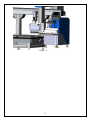
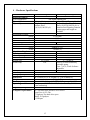
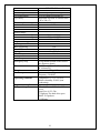
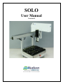
SOLO User Manual Version 6.0 10 Stern Avenue, Springfield, NJ 07081 Tel: 973-376-7400 Fax: 973-376-8265 Index Introduction....................................................................................................................... 3 Section 1 - Hardware ........................................................................................................ 4 1-Unpacking the SOLO .............................................................................................. 4 2 – SOLO Setup .............................................................................................................. 7 2.1 – Ivek Pump Setup ................................................................................................ 7 2.2 – Hamilton Pump .................................................................................................. 8 2.3 – Multichannel ...................................................................................................... 9 3 – Accessories ............................................................................................................. 11 Section 3.1 – Heating/Cooling Nest.......................................................................... 11 Section 3.3 – SOLOPlus ........................................................................................... 12 4 – Hardware Specifications ......................................................................................... 15 Section 2 – Software........................................................................................................ 17 1-Installation ................................................................................................................. 17 1.1 – Installation CD ................................................................................................. 17 1.2 – RS-232 ............................................................................................................. 17 2 – SOLOSoft: Main Screen ......................................................................................... 18 2.1 - Overview .......................................................................................................... 18 2.2 – File Menu ......................................................................................................... 18 2.3 – View Menu....................................................................................................... 19 2.4 – Tools Menu ...................................................................................................... 20 2.5 – Window / Help Menus ..................................................................................... 27 3 – Developing SOLOSoft Methods............................................................................. 28 3.1 – Overview.......................................................................................................... 28 3.2 – Aspirate Step .................................................................................................... 29 3.3 – Dispense Step................................................................................................... 35 3.4 – Get Tip Step ..................................................................................................... 36 3.5 – Shuck Tip Step................................................................................................. 37 3.6 – Loop / End Loop Steps .................................................................................... 38 3.7 – Pause Step ........................................................................................................ 38 3.8 – Move Arm Step................................................................................................ 39 3.9 – Set Speed Step.................................................................................................. 40 3.10 – Prime Step...................................................................................................... 41 3.11 – HitPick Step (available ONLY for single-tip operation modes).................... 42 3.12 – GetLevel Step................................................................................................. 45 3.13 – GetBottom Step.............................................................................................. 47 3.14 – Change Plate Types........................................................................................ 49 3.15 – Operate Accessory ......................................................................................... 50 3.15.1 – Micro10x..................................................................................................... 51 3.15.2 – Ten WayValve ............................................................................................ 51 3.15.3 – Shaker Nest ................................................................................................. 52 3.15.4 – Wait For Input............................................................................................. 52 3.15.4 – Write To Output.......................................................................................... 53 3.15.5 – Hot/Cold Nest ............................................................................................. 53 2 Introduction The SOLO Robotic Pipettor is designed to easily automate complex pipetting tasks that would otherwise prove tedious or error-prone for researchers to perform manually. The SOLO can be controlled as a stand-alone instrument using its easy-to-learn user software, called SOLOSoft. Or, it can be integrated into larger automated systems using its own Active X control. Hudson’s SoftLinx scheduling and workcell control software offers such an integrated interface. In its standard configuration, the SOLO offers 4 plate nest positions, for locating labware such as microplates, disposable tip boxes, fluid reservoirs or other SBS-standard labware. Two additional locations can be added to either the left or right side of the SOLO, to allow a total of six nest locations. Mounted on the side is a flush station with a drain, upon which is mounted a forked fixture for removing disposable tips. An emergency EStop button is mounted on the front body of the SOLO. Pressing this immediately stops all motion of the major (X, Y, Z) axes and causes the normally blue pilot light, located on the upper arm, to turn red. While the E-Stop button is pressed in, arm power is removed from the major axes, allowing them to be manually moved by the user. We currently carry three configurations of the SOLO chassis. The standard configuration includes a either a 125 uL or 250 uL capacity syringe that is mounted on the robot’s vertical axis, offering individual pipetting volumes from 100 nL to 250 uL, and a waste station, and a tip-shucking station to automatically remove disposable pipette tips. The second configuration, offers a syringe pump mounted on the rear vertical frame member, with either 8 or 3 position valves. The syringe is mounted on the pump body and may be easily changed by the user to sizes ranging from 25uL to 10mL per full stroke. This configuration allows the SOLO to perform as both a Pipettor and Dispenser, drawing fluid from any one of up to 7 fluid reservoir bottles. The Third configuration, offers either an 8 or 12 channel multitip pipettor. The 8 and 12 channel heads come in either 10ul or 200ul syringe capacity per channel configurations. The multitip head can be pick up anywhere from one to the maximum number of 8 or 12 tips.. The SOLO also offers an alternate configuration that allows it to become a component in Hudson’s LabLinx track-based stacker system, providing automated feeding and removal of plates and/or tip boxes for high throughput applications. The LabLinx track mounts directly to the SOLO’s deck, taking the place of 2 or 4 plate-nest positions, or even all 6 if very high throughput is desired. The SOLOPlus is a SOLO integrated with Hudson’s Micro10x high speed bulk dispenser. The dispenser is attached to the side of the SOLO with provided hardware. The Micro10x and SOLO share a nest position and SOLOSoft seamlessly controls both instruments through its interface. 3 Section 1 - Hardware 1-Unpacking the SOLO Remove all material from inside the crate except for the SOLO itself. Open the Black nylon strapping that secures the SOLO to the shipping form. Shipping Straps Once the straps are set aside, lift the SOLO by the aluminum bracket that the nest plate holders are secured to. DO NOT LIFT BY THE ARM as this will damage the unit. See Picture on next page 4 Lifting Points on Solo Once the unit is out of the crate remove all the plastic wrapping that secures the arm to the SOLO. Remove Plastic Wrap 5 Once the plastic wrap is removed install the nest plates on the deck of the SOLO. Align the holes in the bottom of the nest plate with the metal dowel pins on the deck assembly and push the nest plates onto the deck. Remove the Power cable and communication cable from their shipping packages and plug them into the correct locations on the SOLO’s rear panel. Install the SOLOSoft on the computer you are going to use with the SOLO. The unit is now ready to startup. 6 2 – SOLO Setup Depending on the version of SOLO that you purchased, there will be different hardware setups before you start using your instrument. We currently carry three types of SOLOs: 1-Ivek Pump (125ul or 250ul) 2-Hamilton Pump (syringe size optional) 3-MultiChannel (8 or 12 Channel configuration) 2.1 – Ivek Pump Setup The Ivek Pump SOLO comes ready to run from the factory. The Mandrel is shipped on the unit, so there is no need to setup anything on the unit. (See Figure 2.1) Unit ships with mandrel installed Figure 2.1 7 2.2 – Hamilton Pump The Hamilton pump SOLO is disassembled during shipping to prevent damage. The glass syringe from the pump is removed before shipping. The mandrel for a disposable tip, or the fixed cannula tip, is also removed before shipping. You may need to home the unit first before you can reinstall the Glass syringe. The cannula tip mandrel is installed by pulling out the plunger that locks the mandrel into the Z-axis assembly. (See Figure 2.2) Plunger for mandrel Figure 2.2 8 2.3 – Multichannel The Multichannel SOLO is disassembled during shipping to prevent damage. The Multichannel head is removed for shipping. To set up; the Multichannel head is pressed into the SOLO’s z-axis. Align the Multichannel head assembly with the Pipettor Drive assembly locking stud. (See Figure 2.3) You will then press the Pipettor head firmly into place until you hear the locking mechanism snap in place. (See Figure 2.4) Lock Engaged Figure 2.3 Figure 2.4 9 The multichannel SOLO has two deck configurations. For the 12 channel the deck will be placed all the way forward towards the operator (Figure 2.5). For the 8 channel head the deck will be placed back in the furthest position away from the operator (Figure 2.6). Figure 2.5 Figure 2.6 Nests all the way back Nests all the way forward 10 3 – Accessories The SOLO has several options that can be purchased in additional to the SOLO they are the following: 1- Heating/Cooling Nest 2- Shaker Nest 3- SOLOPlus (SOLO w/attached Micro10x) Section 3.1 – Heating/Cooling Nest The Heating/Cooling Nest requires the SOLO Accessory Platform. Your SOLO will arrive with the SAP already attached. Unpack the H/C nest and place in the desired location deck location (See Figure 3.1). Attach provided cables. Section 3.2 – Shaker Nest Figure 3.1 The Shaker Nest comes shipped separately from the SOLO. The Shaker Nest has the same alignment holes that are located in the standard nest plates. To install the Shaker Nest; remove one the nest location and install the Shaker Nest in that location (See Figure3.2). Plug in the supplied power/communication cable into the Shaker Nest. Plug 11 the communication cable into an available comport on the USB to serial converter. Figure 3.2 Section 3.3 – SOLOPlus The SOLOPlus option is the addition of a Hudson Robotics, Inc. Micro10x reagent dispenser that is attached to the side of the SOLO (See Figure3.3). The SOLO is equipped with an alignment bracket that is attaches the Micro10x to the SOLO chassis. This alignment bracket can be mounted in the front position of the SOLO, so that the Micro10x nest is located at the SOLO deck position 6, or in the back position, so that the Micro10x nest is located at the SOLO deck position 5. This bracket contains two alignment pins which locate the Micro10x into its proper position. During shipping the SOLO and Micro10x are shipped in different boxes. To install the Micro10x onto the SOLO, you will slide the Micro10x next to the SOLO where the alignment bracket is installed. Slowly lift the Micro10x up, so the bottom of the plastic deck is above the alignment pins. Move the Micro10x into position, so that the alignment holes in the Micro10x plastic deck are aligned with the alignment pins in the SOLO bracket. Slowly move the Micro10x down until the Micro10x deck is located on the pins, and that the bottom the Micro10x deck is sitting flush on the alignment bracket. You may have to adjust the feet on Micro10x to re-level the unit to the SOLO deck. (See Figure 3.4) 12 MC10X Plastic Deck with Alignment holes SoloPlus Alignment Bracket Figure 3.3 13 Figure 3.4 14 4 – Hardware Specifications Hardware features Arm configuration Tip configuration Tip variety Positioning Precision: X-axis Y-axis Z-axis Motion Range X-axis Y-axis Z-axis Liquid handling features Pipetting Bulk Dispensing No of fluid sources Syringe size Wash Pump Safety features Password protection Emergency Stop Dimensions Weight Power requirements Operating conditions Regulatory compliance Computer requirements SOLO Pipettor SOLO Pipettor/Dispenser One liquid handling arm 1 disposable tip 1disposable tip/Pipetting Needle Disposable tips with or Disposable tips with or without without filters filters (10,20,50,100,250 µL) or (10,20,50,100,250 µL) Stainless Steel Pipetting Cannula, various gages and length are available. ± 0.025mm ± 0.025mm ± 0.004mm 594mm (23 3/8") 244mm (9 5/8") 101mm (4") ٧ N/A N/A 125, 250µL N/A ٧ ٧ 1,3,5,7 25 – 10,000 µL Delivery of wash solution by peristaltic pump. Flow: 7,14,21,28 mL Software adjustable. E-stop Button located on the front of the dispenser chassis W. 556mm (30") x D. 483mm (19") x H. 610mm(24") 27 kg (60 lb) Power: 60VA Voltage: 100-240VAC, Frequency: 50/60HZ Temperature 15-32°C/ 59-90°F, Relative humidity 30-80% (non condensing) PC with Microsoft Windows XP or newer Quad Core @ 2.5 Ghz 3 Gigabytes free hard drive space RAM : 4 Gigabytes 1 USB port 15 Hardware features Arm configuration Tip configuration Tip variety SOLO Multichannel Multiple liquid handling arm 12 or 8 Channel Disposable tip Disposable tips with or without filters (20 or 200 µL) Positioning Precision: X-axis ± 0.025mm Y-axis ± 0.025mm Z-axis ± 0.004mm Motion Range X-axis 594mm (23 3/8") Y-axis 244mm (9 5/8") Z-axis 101mm (4") Liquid handling features Pipetting ٧ Bulk Dispensing N/A No of fluid sources N/A Syringe size 10 or 200 µL Wash Pump N/A Safety features Password protection Emergency Stop E-stop Button located on the front of the dispenser chassis W. 556mm (30") x D. 483mm (19") x Dimensions H. 610mm(24") 27 kg (60 lb) Weight Power: 60VA Voltage: 100-240VAC, Power requirements Frequency: 50/60HZ Temperature 15-32°C/ 59-90°F, Operating conditions Relative humidity 30-80% (non condensing) Regulatory compliance PC with Microsoft Windows XP or Computer requirements newer Quad Core @ 2.5 Ghz 3 Gigabytes free hard drive space RAM : 4 Gigabytes 1 USB port 16 Section 2 – Software 1-Installation 1.1 – Installation CD Place the SOLOSoft Installation CD in your CD drive. It will automatically begin the Installation process. It will create a folder “C:\Program Files\ SOLOSoft” where the SOLOSoft executable files, the SOLOSoft Active X control, plate definition Access database and support files are loaded. This folder is also the default folder for all SOLOSoft methods, which have the file extension “.hso”. Several sample methods are loaded from the CD as well. 1.2 – RS-232 Most users will choose to use the included RS-232 cable to connect their computer to the SOLO. If you are using RS-232, a 9-pin female RS-232 connector is located on the rear panel of the SOLO. Connect the provided cable here and either to the serial port on your computer, or to a USB to serial converter. Selecting the serial port assignment and communication parameters is covered in another section of this manual. 17 2 – SOLOSoft: Main Screen 2.1 - Overview Upon Startup, SOLOSoft presents the ‘Log In’ display, which shows the current Version and a “Log In” button. Click on the button, then enter your name and password. On initial usage, the default User Name is “User” with a blank password. Under the “Tools Menu” discussion below are instructions about setting up actual user names and their passwords. After entering a valid user name and password, the ‘Main Screen’ display is shown, as below: Clicking on any of the five options on the Menu Bar provides the menu features described in the following subsections. 2.2 – File Menu New – This option creates a blank method whose default name is “Document1”, and the user can now start developing a new method as described in the ‘Method Development’ section below. The new method can then be saved under the “Save As…” option described below+. Open – This option allows the user to open an existing method, either to run it or to edit it. The default storage folder for existing methods is “C:\Program Files\SOLOSoft”, however a browse window allows the user to for a method file that may be located elsewhere. Multiple methods may be open at the same time, with the currently active method being the one whose display is out front. Close – This will close the currently active method (the one in front) only. Close All – This will close ALL open methods. 18 Save – This will save the currently active method only, using the path and name shown along the title bar of that method. Save As… This allows the user to select a different path and/or name for the currently active method. This new path.name will then appear in its title bar. Print – This will send the currently active method to the user’s printer in a text format. Exit – This selection will close SOLOSoft. 2.3 – View Menu Toolbar – Checking this option displays the Toolbar buttons along the upper left area of the Main Screen, immediately below the Menu Bar. Unchecking this hides these. Status Bar – Checking this option displays the status bar across the bottom of the Main Screen. Unchecking it hides this bar. Enable Logging – Checking this option will establish a Method Log File for each method that is run. Every step executed by the method will have its date and time of completion logged, along with process data applicable to that step (if any). The log file is saved in the same folder as the SOLOSoft application, and has the file name “MethodName YYYY-MM-DD HH-mm-SS.log”, where MethodName is without the “.hso” extension, and the date/time in the name refers to the moment that method is started. Refresh – This refreshes the display of currently opened methods. 19 2.4 – Tools Menu Simulated Configuration – This option is only active when the communications port (see Communications…, below) is set to <none>, forcing SOLOSoft into Simulate Mode. This allows the user to try out different SOLO configurations, such as switching between ‘P’, ‘D’, ‘P8’ and ‘P12’ syringe configurations, changing syringe volume, and switching from Landscape to Portrait layout: System Liquid (not applicable to simulation mode) a. ‘P’ Syringe Type (Z-axis mounted syringe) – This option allow the user to move the syringe piston Up (Aspirate) or Down (Dispense) where only the syringe piston moves, not the robot axes: Aspirate – the user can enter a volume (uL) , or by leaving the volume at “FILL”, run the syringe piston all the way to the top of its stroke. Dispense - the user can enter a volume (uL) , or by leaving the volume at “EMPTY”, completely empty the syringe by running the syringe piston all the way to the bottom of its stroke. 20 b. ‘D’ Syringe Type (Side-mounted valved syringes) – This option allow the user to move liquid from any of the systems fluid reservoir vessels to or from the tip. For both Aspirate and Dispense, the reservoir is selected by selecting the appropriate Valve Port in the displayed input box: Aspirate – the user can enter a volume (uL) to move from the tip to the reservoir (even volumes greater than the syringe’s volume), or by checking the ‘Continuous’ operation box, run the syringe piston continuously until the user clicks on the “Halt” button. The ‘No. Strokes’ box can be checked and the desired number of aspiration strokes entered as another operation option. If there are multiple syringe pumps on the SOLO, the Syringe box will drop down to allow the user to select any individual syringe or, at the bottom of the list, “ALL” syringes operating together. Dispense – the user can enter a volume (uL) to move from a reservoir to the tip (even volumes greater than the syringe’s volume), or by checking the ‘Continuous’ operation box, run the syringe piston continuously until the user clicks on the “Halt” button. The ‘No. Strokes’ box can be checked and the desired number of dispensing strokes entered as another operation option. 21 Calibrate Deck… – This option allows the user to create, teach, save or delete robot positions within the working area of the SOLO’s 3-axis robot arm, as well as to jog the arm within that work area. Clicking this option will produce the following screen display: The first 8 position names in the list are PERMANENT and cannot be deleted, however, the user can re-locate them anywhere within the work area of the robot, however they are intended to be located properly for use in the SOLO’s plate nests and tip shucking/flushing stations as follows: Position1 – the left hand rear plate-nest location. It should be programmed with a disposable tip pressed onto the syringe tip mandrel (in the case of a SOLO with this option), or using the fixed tip. It is intended to be programmed with a 384-well plate. Align the tip between locations A1,A2,B1, and B2. This simulates the center of well A1 in a 96-well plate located in that nest position ‘A1’ being located in the rear left corner of the plate-nest. Upon clicking the “Save Point…” screen button, SOLOSoft will save this point name with the current X- and Y- axis coordinates, and set the Z coordinate equal to the Z-axis’ current ‘travel height’ setting. This Z-axis setting applies to all 4 (or 6, for Portrait layout) of the plate-nest positions listed here. Position2 – the lefthand front plate-nest position. Position3 – the middle rear plate-nest position. Position4 – the middle front plate-nest position. Position5 – the righthand rear plate-nest position. Position6 – the righthand front plate-nest position. Flush – located with the tip in or above the waste drain fixture. 22 TipDisposal – located where the syringe tip is within the tip-stripping fixture, with the forks of the fixture surrounding the syringe tip mandrel, and just above the top of a disposable tip so that an upward movement of the robot will strip off the disposable tip. The coordinates of any position selected from the list along the left will be shown in the box entitled “Position Coordinates(steps)”. The user can directly modify these coordinates, then move to the modified coordinates. However, the actual saved coordinates of that position will NOT be overwritten unless the user clicks on the “Save Point at Current Location” button on the right. The screen button “Set Skew” allows the user to adjust the calculated locations Of plate wells in case an individual nest is not in perfect alignment with the X- or Y-axes. Pressing this button when teaching a plate nest position will provide the user with instructions on how to make this adjustment. This is important particularly when dealing with 1536-well plates. The screen button “Relax Motors” can be used to remove power from all 3 robot axes, allowing the user to manually maneuver the tip to the desired location. Clicking on that button again will restore motor power. Change Password…This allows the current user to change his/her password, which will then apply to any subsequent log-ins. Users… – This allows a user of Level 3 to add or delete users from the system’s database. Login… This allows the user to login using his/her User Name and Password. The User Level will become that of the newly logged-in user. Notes on User Level Restrictions: User Level 1: Intended for users who can operate the SOLO but are not allowed to open, change, save or close methods, or use the Communication utility. Level 1 users can run already loaded methods, teach/modify deck positions and change their own passwords. User Level 2: Level 2 users cannot create new methods, add or delete users, or use the Communications utility. All other SOLOSoft functions are available to Level 2 users. User Level 3: All SOLOSoft functions are available to Level 3 users. 23 Define Plate Types… This enables the user to define the properties of the various microplates that will be used in the SOLO. The following screen is displayed: The user creates a new plate by placing the mouse cursor in the last row of the “Name” column, then typing in the name of the new plate. The user must also enter the number of “Wells” (the SOLO will calculate the center of each well based upon this), the “Height” of the top of the plate from the nest surface, then, in the 4th column, enter the depth of the bottom of the plate’s wells, measured from its top surface. This “Depth” will be limit below which the SOLO needle or disposable tip will not travel when aspirating or dispensing within a SOLOSoft method. See image below. When defining disposable tip box parameters, the “Height” value should be the height of the top of the disposable tip, as it rests in the tip box, above the surface of the plate nest. The 4th column will contain the "Tip Length", that is, the length (mm) of the disposable tip itself. See image below. This data is saved in an ACCESS database table “C:\Program Files\SOLOSoft\SOLOSoft.mdb”. This must be opened directly if the user wishes to delete a plate type. 24 Communications… This enables the user to select the serial port to be used by the computer to control the SOLO. A drop-down list of available serial ports will be displayed by clicking on the down arrow in the list box shown below: The ‘Terminal Window’ button provides a HyperTerminal window which will use the Serial port selected in the ‘Communications Port’ list box to enable the user to use the SOLO’s ASCII Command Set (see Appendix A). The user can then issue commands directly to the SOLO from the computer keyboard. 25 Accessory Devices: If the SOLO has the Shaker Nest, Micro10, Hot/Cold Nest, 10-Way or 4-Way Valve Accessories, the user would setup a serial port to control each accessory in the same manner as for the SOLO itself, by clicking on the appropriate tab in the form shown above and selecting the desired COM port. Each device also has its own ‘Terminal Window’ to allow the user to issue individual commands to it using its own ASCII command set. 26 2.5 – Window / Help Menus The Window menu enables the user to manipulate the window display patterns familiar to users of MicroSoft Windows products. The Help menu’s ‘About’ option will show the current version of SOLOSoft. 27 3 – Developing SOLOSoft Methods 3.1 – Overview SOLOSoft enables the user to create, save and run pipettor processes called ‘methods’. A method consists of a series of sequential actions, called ‘steps’ that the SOLO will execute when that method is run. Methods are created and modified using a “drag and drop” editor that is started when the user opens a new method or an existing one, using the File Menu described above. Using the File Menu to select the “New” option will display the following screen: The user adds each desired method step by “dragging” any of the ‘Step’ buttons, in the toolbar at the upper left, into the white field immediately below, arranging the steps in the order desired by the user. As each step is “dropped” into the white field, the grey area to the right will provide a GUI specific to that type of step that allows the user to define parameters for that step. A completed method will consist of a series of steps arranged in a single vertical column, much like a flow chart. Step types available to the user are described below. 28 3.2 – Aspirate Step This step will move the pipettor to a selected aspirate position, then aspirate the indicated volume of fluid. The display shown below depicts an Aspirate step drawing 95 uL from well ‘A3’ of a 96-well plate located at Position1 on the SOLO’s deck on its first execution, then 75 uL from well ‘C4’ on its second execution (see the LOOP step below): The user has a number of parameters to select in an Aspirate step: Select Type of Source – Plate Position: A ‘Plate Position’ can be selected and identified by clicking on one of the 4 possible deck plate-nest positions (Position1 to Position4) in the deck image above the selection box. ‘Named’ Point: if this is selected, the screen will change to that shown at the end of this subsection below, allowing the user to select ANY taught position, whether or not associated with a plate-nest. The available points are selected from a drop-down list shown near the center of the display, and the user would enter the desired volume in the box immediately above this. 29 Increment Order – (applies only to aspirating from a plate position for SOLO equipped with single tip pipettor head or multi-tip pipettor head used in ‘Single Tip Mode’) Row Order (disabled for multi-tip option of ‘P8’type syringe) : If a multiple number of wells per execution is entered, or if this step is within a Loop, each aspiration will increment in the order “A1, A2, …. , A12, B1,…, B12, etc.”. Column Order(disabled for multi-tip option of ‘P12’type syringe): “A1, B1, … , H1, A2, …, H2, etc.”. Reverse Order: wells with non-zero volumes are selected beginning at H12 (for a 96-well plate) instead of A1. Row or Column order rules apply, but in reverse. Note: For multi-tip ‘P8’ syringe all non-zero volume wells in each row will be addressed before moving to the next row. Note: For multi-tip ‘P12’ syringe all non-zero volume wells in each column will be addressed before moving to the next column. Any wells with a zero volume will be skipped by single-tip units and not included in the increment count. Syringe (uL) – This is read from the SOLO’s firmware and is selected from a dropdown list of the syringes actually on this unit. Start by Emptying Syringe (‘Pn’ syringe type only, where n is 0,1,8 or 12) Checking this box will cause the needle or tip to move over the intended aspirate position, then the syringe piston will move to its bottom (empty) position at the start of this step. This is useful to ensure that the full capacity of the syringe is available for this aspiration. Otherwise the aspiration will start at the last position of the syringe piston. Find Bottom of Vessel or Well – If this box is checked, the tip will travel down under low power until it stalls on the bottom of the plate well or tube. Then, it will rise by the distance in the Z Shift box under the ‘Aspirate Shift’ parameters. Mixing – If the box is checked, immediately after either dispence or aspiration, the SOLO will dispense then aspirate the amount in ‘Mix Volume’, for the number of times given by the ‘Mix Cycles’ value, ending with a final dispense to leave the mixed sample in the well or vessel. The aspirating action of the mixing will take place at the height indicated by the ‘Z Shift’ entry, while the dispense action will occur at the ‘Dispense Height’ distance from the well bottom (for plates) or from the taught point. Valve Port (‘D’ syringe type only, not shown) – The user must select the appropriate fluid reservoir by choosing the correct valve from a drop down list for the selected syringe pump. 30 Syringe Speed – Scroll up or down to accelerate or slow the syringe piston’s movement. Pre-Aspirate – Enter this volume to aspirate air before each aspiration event in this step. This allows air pockets to separate each individual aspirated sample, and also allows the dispense volume to “blowoff” with an air pocket to forcibly expel tip droplets at the end. Backlash – Enter the number (the default is 0) of uL that you wish to have the syringe piston move in reverse at the end of its stroke. This is used to control droplets or end-of-tip air gaps (also used in a Dispense step) for a given commanded volume. Multiple Wells – The number of aspirations done in each execution of this step, in the selected row or column order. Any wells with a zero volume will be skipped and not counted in the number selected. Note: For multi-tip ‘P8’ only column order is available and for ‘P12’ syringe only row order is available . Switch to File Data – If the ‘Switch to File Data’ option is selected, the user will be shown a browse screen to browse for the file or to just enter its name. The selected file and its path will be shown just below the button’s location. The text on the button will change to “Switch to Entered Data” to enable the user to go back to using the plate image table across the bottom of the display, and manually enter volume values for each well or the named point. The file structure will be determined by which type of position is to be aspirated from: Aspirate from Plate Position: The volume to be aspirated from each well can be imported from a comma-separated text file with a row/column format that matches the plate type selected for this position (e.g., 8 rows of 12 values each for a 96-well plate). This file lists each row on a separated line, with each column’s value separated by a comma, resulting in a file similar to that shown below for a 96-well plate: 50,58,66,74,82,90,98,106,114,122,130,138 51,59,67,75,83,91,99,107,115,123,131,139 52,60,68,76,84,92,100,108,116,124,132,140 53,61,69,77,85,93,101,109,117,125,133,141 54,62,70,78,86,94,102,110,118,126,134,142 55,63,71,79,87,95,103,111,119,127,135,143 56,64,72,80,88,96,104,112,120,128,136,144 57,65,73,81,89,97,105,113,121,129,137,145 31 The file for a 384-well plate would have 16 rows of 24 values each. For multi-tip operation only values for wells addressed by first tip of multi-tip head are taking in consideration. Tips on the head are counted from left to right. See bellow file list for aspirating with 12 tip head (‘P12’) from 96-well plate: 50, 50, 50, 50, 50, 50, 50, 50, 50, 50, 50, 50 42, 42, 42, 42, 42, 42, 42, 42, 42, 42, 42, 42 0, 0, 0, 0, 0, 0, 0, 0, 0, 0, 0, 0, 0 0, 0, 0, 0, 0, 0, 0, 0, 0, 0, 0, 0, 0 0, 0, 0, 0, 0, 0, 0, 0, 0, 0, 0, 0, 0 0, 0, 0, 0, 0, 0, 0, 0, 0, 0, 0, 0, 0 20, 20, 20, 20, 20, 20, 20, 20, 20, 20, 20, 20 10, 10, 10, 10, 10, 10, 10, 10, 10, 10, 10, 10 Well positions that have zero (or negative) volume values will simply be skipped. The SOLO will aspirate from the number of non-zero wells determined by the “Multiple Wells” setting, then, if inside a “Loop” , will start at the well following the last one aspirated during the previous execution of this step. The volumes to be aspirated will appear in their respective well locations in the plate image across the bottom of the display. Aspirate from ‘Named’ Point: The volume to be aspirated from a point, such as a vial location, can also be imported from a comma-separated text file, but for this type of position, the values can be in any number of rows/columns, and are read in left-to-right, top-to-bottom order. As in the case of aspirating from a plate position above, any zero (or negative) volume values will simply be skipped. The SOLO will aspirate the next nonzero volume in the file. If inside a “Loop”, it will use the value following the last one aspirated during the previous execution of this step. A complete list of the values to be aspirated can be viewed in the dropdown’ list inside the “Aspirate Volume(uL)” box. 32 Aspirate Shift – This enables the user to adjust the actual aspiration location from the taught position selected for aspiration. This enables the user to go to a ‘non-standard’ location, or to move in other than well-spacing increments. For plates, the “Z Shift” value is the distance above the well bottom that aspiration will occur, with a maximum value of the plate’s well depth. For named points, it is the distance above or below that taught point’s height. Do Tip Touch / Tip Touch Shift – This enables the user to do a ‘tip touch’ to clean a droplet off the tip, and to specify where that tip-touch will be relative to the actual aspiration location. Any shift done in the ‘Aspirate Shift’ selection above will affect this ‘aspirate location’. This will cause the tip to touch twice, on opposite sides of the well or vessel. Aspirate Volumes (table) – This graphic shows an image of the plate type selected for this step, and enables the user to enter distinct volumes for each well in the plate. (Important: be sure to pres <ENTER> after entering the last volume into any well location, as it will not be saved if you don’t!). As a convenience, you may enter a value in the first element of any row or column, then click on the row/column number to set every well in that line to that value. Liquid Level Detect – Units equipped with the Liquid Level Sensing option allow the user to check the box “Liquid Level Detect” box, which will cause the pipette tip to seek the surface of the liquid in the well or vessel being aspirated. If this is checked, a text box labeled “Max. Depth (mm)” is shown. The user should enter the maximum depth of the tip below the 33 upper rim of the well or vessel, below which it will not proceed if no liquid is detected. If aspirating from a defined microplate, and the entered “Max. Depth” value exceeds the Plate Depth value, that plate’s Plate Depth value will be used, so as not to drive the tip beyond the bottom of the well. A typical display showing the Liquid Level Detect feature is shown below: When using liquid level detection, the “Z-shift” value in the “Aspirate Shift” box indicates the distance to move the tip below the detected liquid level prior to aspirating. If the tip reaches the “Max. Depth” position without detecting liquid, the Aspirate step will end and SOLOSoft will perform its next action. 34 3.3 – Dispense Step This step will move the pipettor to a selected dispense position, then dispense the indicated volume of fluid. The display shown below depicts a Dispense step expelling 95 uL into well ‘C2’ of a 384-well plate located at Position1 on the SOLO’s deck on its first execution, then 75 uL into well ‘C6’ on its second execution: The parameter selections are identical to those of the Aspirate step, except for the following: Mixing – Same as Aspirate step, except in opposite order, but ends with a dispense as well. Blow-off – This amount will be expelled from the syringe after the last ‘dispense’ amount in this step is released. It is used to blow off a droplets that may be on the tip at the end of dispensing. 35 3.4 – Get Tip Step This step, whose GUI is shown in the next figure, will start by shucking any tip that may have been left on the mandrel from a prior activity, then move to the next tip position in a tip box located at, in this example, Position1: The location of the tip box is selected by clicking on the appropriate nest position in the displayed deck image. At the start of this step, the SOLO will attempt to shuck the tip (or tips), in case the tips were left on the mandrel from a prior operation. If the position selected in the “Select Disposal Point” box is the same as the plate nest where the tip box is located, the tips will be shucked into the last box position emptied. However, if a method was just loaded, if the tip box is full, or if a multi-tip unit is being used with fewer than its maximum tip count (i.e., 8 or 12), then the tip shuck will occur at the position in the “Select Disposal Point” (if it is different from the location of this tip box) or at the “Tip Disposal” position by default. For all syringe types SOLOSoft keeps track of tip count in tip boxes between methods and even if closed and powered-down. For single-tip units the tip retrieved in this step will be the next tip in the box, counted across the box in ‘row order’, starting from the H12 (or P24) well position. For multi-tip syringe types ‘P8’ and ‘P12’ SOLOSoft keeps track of tips available in tip box for both singletip and multi-tip operations. 36 The tip box will be reset to “full” if the type of box at that location is changed, if the identity of that tip box is changed (e.g., if operated using Hudson’s SoftLinx scheduling software and a new tip box is moved into that position), or if the tip box is reset in the “Change Plate Types” utility (see that subsection below). In the step’s graphic plate image, available tips are shown in GREEN. For a single-tip syringe type, each tip will be taken sequentially from the first available position along rows starting with row H and progressing in direction from column 12 to 1 and then rows H to A (for 384-well boxes, substitute “P” for “H” and “24” for “12”). For multi-tip syringe type ‘P8’ utilizing ‘single-tip’ option the single tip will be taken sequentially from the first available position along columns starting with column 12 and row H progressing in direction from row H to A and then columns from 12 to 1. In case of using ‘multi-tip’ option, tips will be picked up from first column with enough tips to meet the “Number of Tips to Use” entry, starting with column 12. For a multi-tip syringe type ‘P12’ utilizing ‘single-tip’ option the single tip will be taken sequentially from the first available position along rows starting with row H and progressing in direction from column 12 to 1 and then rows H to A. In case of using ‘multi-tip’ option, tips will be picked up from the first row with enough available tips, starting with row H. For guidance on programming tip pickup positions and using different length disposable tips in different methods, see the subsection below entitled “Programming with Disposable Tips”. 3.5 – Shuck Tip Step This step, whose GUI is shown in the next figure, allows the user to discard a disposable tip at the position indicated in the “Select Disposal Point” box. This is usually used at the very end of a method to strip off a remaining tip. Otherwise, the “Get Tip” step is normally used to shuck a tip prior to getting another. 37 3.6 – Loop / End Loop Steps These steps, shown in the next figure at the top and bottom of the method flow diagram, allow the user to repeat sequences of steps the number of times indicated in the “Enter NUMBER of Loops to Perform” box. After repeating every step between these two loop steps, the method will continue with the next step after the ‘End Loop’ step. Loops can be nested within other loops. If, for instance, a loop with 3 repeats is nested inside a loop with 2 repeats, the steps inside the inner loop will be executed a total of 6 times, while those within only the outer loop will be executed 2 times. SOLOSoft will pair each ‘Loop’ step with the very next ‘End Loop’ that appears in the method. Any ‘Loop’ without a matching ‘End Loop’ will be ignored. 3.7 – Pause Step This step, shown in the next figure, allows the user to pause the run and present 38 a message to the operator. It also allows the user to permit the operator to end the method at the time of the pause (if, for instance, no liquid was aspirated). The user types the desired message into the “Enter pause message” box, and allows the operator to end the method by checking the “Allow user to end run at this step?” box. The user may also simply set a timer (in seconds) to pause the method here, then automatically resume after the time has elapsed. 3.8 – Move Arm Step This step, shown in the next figure, allows the user to simply move the robot arm to any taught position at a speed given as a percentage of the arm’s full speed in the “XYZ Speed” box. The ‘X’ and ‘Y’ axes move first, followed by the ‘Z’ axis. 39 As an option, by checking the “Move ‘Z’ Axis…” box, the tip will move up to its normal travel height prior to moving laterally to the selected destination position. 3.9 – Set Speed Step The default robot arm speed is 100% of full speed. This step, shown in the next figure, allows the user to set the movement speed for subsequent steps at the percentage of full speed depicted in the “XYZ Speed” box. This will be overridden by the value set in any “Move Arm” step that may follow. 40 3.10 – Prime Step The Prime step allows a user to prime or evacuate “D” type syringe liquid lines, or to position a “P” type syringe piston at a desired position, at the start of a method, or even at intermediate places in a method. The display for a SOLO equipped with a “D” type syringe appears as follows: A SOLO can have multiple “D” type syringe pumps (up to 10), and this step allows any individual syringe pump to be exrcised, or all at once. If all are exercised at once, the “Total Volume” selection is greyed-out, and only the “Strokes” selection is allowed. Also, the valve port selection must be the same for all. The display for a SOLO equipped with s type “P” syringe appears as follows: 41 The user make elect to position the syringe piston at the very top of its stroke (FILL) or position it at the bottom of its stroke (EMPTY). Alternatively, the syringe may be moved by a selected amount (in uL), either up (Aspirate) or down (Dispense). 3.11 – HitPick Step (available ONLY for single-tip operation modes) The HitPick Step provides the user with a convenient way to consolidate the contents of selected wells from one or more source plates into one or more target plates. This step can be used for cherry-picking, rearraying and re-formatting from one size plate to another. The HitPick step is setup much as if it were an Aspirate Step and a Dispense Step combined into one. The user chooses the syringe selection, syringe speed, X,Y,Z offsets and Tip Touching are similar to those in the Aspirate and Dispense Steps described above, and are not repeated here. The user must select the Source plate’s position (out of the available plate nest positions 1 through 6) and the target plate’s position. These selections will also define the type of plate that will be present at each of these positions while running, just as in the Aspirate or Dispense Steps above. The major differences between the HitPick Step and the Aspirate or Dispense Steps are: a. The Source plate’s data ALWAYS comes from a .CSV file, for which the user selects the folder where the source file(s) will be found. b. The Target plate’s information is derived from a “blocking” pattern that is stored with the method. c. The user selects an Output file and file path where the transfer information is to be stored (the same file for all plates in a run). There must be a separate source file for each Source plate, where that file’s name is SourcePlateBarcode.csv. For instance, if that Source plate’s barcode is 42 “ABC123”, then the file’s name would be “ABC123.csv”. The file contents are simply the well name of each source well, followed by a comma then the amount (uL) to be transferred into each target well. The format would looks as follows: A01,50 C09,75 H11,55 (each well,volume entry is on a separate line) The user can use a header line, if desired, of “Source,Well” for clarity. This line is ignored by SOLOSoft if present. The HitPick Step allows the user to fill multiple target wells from each source well, and the amount aspirated from the source well will be that multiple of the amount in the source file. That is, if the user elects to fill 3 target wells from each source well, the amount aspirated from well “A01” above would be 150 uL, with SOLOSoft multiplying the amount in the source file by 3. Each line in the output file has the format “Date,Time,Source Plate Barcode,Source Well,Target Plate Barcode,Target Well,Amount (uL)”, with no header line. A typical entry would appear as follows: 6/23/2008,2:40:24 PM,ABC123,A03,DEF456,A01,53 The picture below shows the HitPick Step’s graphic image: The user can select a Maximum Volume per Aspiration to allow the use of pipette tips that may be smaller than the amount needed to complete the transfer, and may set the number of Target Wells per Source Well. The SOLO will only aspirate up to the Max. Volume each time. If more than one Target Well is to be filled per Source Well, the SOLO will divide that maximum volume by the number of 43 target wells and dispense equal amounts in each until they receive the full amount required. In order to reduce any effect from pipetting residual volumes at the very lowest end of the pipette tip’s range, the next-to-last aspiration step will be limited to 50% of the total remaining aspiration volume so that the last aspiration is also at least 50% of the Max. Volume setting. The user can browse the computer for the appropriate folder where Source plate files will be found, and can browse or simply enter the full path and name of the output file. Then, before saving the method, can select those Target plate rows, columns or individual wells which will be blocked from receiving transfers from the Source plate. These will be colored black as in the above graphic. The user can also select whether to fill the Target plate in “Row” (across the top, then down) or “Column” order. Pending but un-aspirated “hit” wells on the Source plate are displayed in yellow, while completed transfers are shown in green on both plates. If the Source Plate’s “hits” have all been transferred, or if the Target Plate is full, the HitPick Step will end, and, if this step is imbedded inside a Loop, that Loop will end and the Method will proceed with the next step beyond that Loop’s End Loop step. Usually, the Method will have been designed to end here to enable replacing either of the finished plates. Not shown in the graphic above are the aspiration and dispensing settings that the HitPick Step has in common with the Aspirate and Dispense Steps, which are in the lower portion of the HitPick Step’s graphic. Also, a ‘Mix’ option is provided for both the Source and Target plate wells which functions identically to those in the Aspirate and Dispense Steps, described in those sections. 44 3.12 – GetLevel Step The GetLevel step allows the user to detect and record, in a file, the liquid level inside selected wells in a microplate located at one of the SOLO’s six plate nests. The user begins by selecting the plate nest (and its type of plate) where the microplate being measured will be located. Next, using the “Browse…” button depicted in this step’s display (below), the user selects the location and name of the file where the liquid level data will be saved. The user should also select the “Search Speeds” (as percents of full speed) at which the probe tip will descend to the liquid surface, and the speed at which the syringe piston will expel air until the surface is reached. The user must then 45 select the number of wells to search (entering “-1” to select all unblocked wells), the depth to which the probe should travel before stopping (that plate’s well depth, as listed in its definition – see Define Plate Types… above - is the limit for this setting), and the distance above the plate to begin the actual search. The user would then select the order for incrementing the probe from one well to the next (“Row” or “Column” order), and may block out individual wells of entire rows or columns by clicking on the plate graphic at those wells or rows/columns. Those wells thus appearing in BLACK will not be measured. It is then up to the user to actually use the file data this step produces, such as in a special VB step in SoftLinx or another external software application. One line of comma-separated text data is written to the file per well as follows: Format: Date,Time,Plate Barcode,Well ID,Liquid Depth(mm) Example: 9/28/2011,12:33:40 PM,ABC123456,A03,7.03 46 3.13 – GetBottom Step The GetBottom step allows the user to detect and record, in a file, the level of the bottoms of selected wells in a microplate located at one of the SOLO’s six plate nests. The user begins by selecting the plate nest (and its type of plate) where the microplate being measured will be located. Next, using the “Browse…” button depicted in this step’s display (below), the user selects the location and name of the file where the well bottom data will be saved. 47 The user should also confirm the “Search Params” (as percents of full speed and force) at which the probe tip will descend to the surface being measured. The user must then select the number of wells to search (entering “-1” to select all unblocked wells), and the distance above the plate to begin the actual search. The user would then select the order for incrementing the probe from one well to the next (“Row” or “Column” order), and may block out individual wells of entire rows or columns by clicking on the plate graphic at those wells or rows/columns. Those wells thus appearing in BLACK will not be measured. It is then up to the user to actually use the file data this step produces, such as in a special VB step in SoftLinx or another external software application. The saved measurement is the detected height of the well bottom above the DeckHeight of that plate nest. The data is written to the file per well as follows: Format: Date,Time,Plate Barcode,Well ID,BottomHeight(mm) Example: 9/28/2011,12:33:40 PM,ABC123456,A03,3.03 48 3.14 – Change Plate Types This utility allows the user to select the type of microplate (or tip box, omni tray, etc.) that is located in any of the 4 plate-nest positions. It also allows the operator to reset any used tip box count to zero, which would have the SOLO start retrieving tips at the ‘A1’ tip position. To change a plate type at any of the 4 positions, or to add a plate where the nest was empty, click on the ‘down’ arrow of the box for that position, and a list of all the defined plate types in the SOLOSoft database will be shown. Clicking on the desired plate will add it to that position. The ‘OK’ button will save the changes, while the ‘Cancel’ button will restore the original data. These changes will take effect immediately and remain so while this method is loaded. In order to preserve these changes the next time this method is loaded, the method itself must be saved upon closing it. 49 3.15 – Operate Accessory This utility allows the user to operate any of several optional accessories that are available for the SOLO. Drag down the ‘Operate Accessory’ button to select this type of step. Then select the individual accessory by clicking on its icon button in the display shown below: The individual accessory selected will be shown as described below: 50 3.15.1 – Micro10x Selecting the Micro10x action for this step will change this step’s display to appear as follows: This option allows a SOLOPlus to perform rapid dispensing from an attached Micro10x. The user can select to run a dispense or prime program, or to empty the fluid back into its source. Dispense and prime programs are configured ahead of time in the Micro10x itself. Consult the Micro10x manual for more information on creating and editing dispense and prime programs. 3.15.2 – Ten WayValve Selecting the Ten Way Valve action for this step will change this step’s display to appear as follows: This option allows a SOLOPlus with an attached Ten Way Valve input for the Micro10x to modify the fluid being dispensed by the Micro10x. Execution of the step results in a change in the input valve port on the Ten Way Valve. It is recommended to re-prime the Micro10x after switching fluids. Optionally, the user may want to empty the Micro10x before changing fluid sources to conserve liquids. 51 3.15.3 – Shaker Nest Selecting the Shaker Nest for this step will change this step’s display to appear as follows: This enables the user to set the speed, duration, acceleration and mode of shaking action for up to 4 nests in one step, if it is so-equipped. 3.15.4 – Wait For Input Selecting the Wait For Input action for this step will change this step’s display to appear as follows: This option allows a suitably configured SOLO to pause here until a digital input signal with the value of “Target Value” (1 or 0) is received from another device, such as a robot or a user-operated pushbutton. 52 3.15.4 – Write To Output Selecting the Write To Output action for this step will change this step’s display to appear as follows: This option allows a suitably configured SOLO to set a digital output signal to the “Target Value” (1 or 0) to provide a signal to device, such as a robot or a mechanical system. 3.15.5 – Hot/Cold Nest If the SOLO is equipped with the Hot/Cold Nest accessory, the user can select the temperature setpoint as well as several optional ways to use this temperature-controlled nest: 53 The user would enter the desired temperature to be achieved (the SetPoint) in the appropriate box. The range is -10.0 to 110.0 Deg.C. When a Method is running, the “Actual:” box will display the actual temperature of the Nest. The user has several optional ways to execute this step: Turn Nest OFF at End of Method: un-checking this will allow the user to keep the heating/cooling action running after the running Method ends. If this remains checked, it will turn OFF at the end of a run. Don’t Wait: this will send the SetPoint to the Nest, starting heating/cooling action, but then will immediately continue to the next step in this method. Wait Until Actual = SetPoint: this will cause this step to hold here until the Nest’s actual temperature reaches the targeted SetPoint, then will immediately move on to the next method step. Wait Until Temperature is Stable: this will cause this step to hold here until the actual temperature stops changing, even though SetPoint may have been reached before this. Turn Nest OFF Now: checking this will simply use this method step to turn the heating/cooling action OFF, then the step will exit. Turn Nest OFF at Temperature: this will turn the nest OFF immediately upon satisfying either of the previous two selections, then advance to the next method step. Log Temperature @: checking this box will cause this step to log the ACTUAL temperature to the SOLOSoft log file at intervals given by the entry in the accompanying box (in seconds). This logging will continue even after this step exits, until the method ends. 54