1
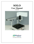
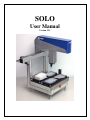
SOLO
User Manual
Version 5.15
10 Stern Avenue, Springfield, NJ 07081
Tel: 973-376-7400 ♦ Fax: 973-376-8265
Index
Introduction 4
Section 1 – Hardware
5
1-Unpacking the SOLO .................................................................................................. 5
2 – SOLO Setup .............................................................................................................. 8
2.1 – Ivek Pump Setup ................................................................................................ 8
2.2 – Hamilton Pump .................................................................................................. 8
2.3 – Multichannel ...................................................................................................... 9
3 – Accessories ............................................................................................................. 10
Section 3.1 – Heating/Cooling Nest.......................................................................... 11
Section 3.2 – Shaker Nest ......................................................................................... 11
Section 3.3 – SOLOPlus ........................................................................................... 11
4 – Hardware Specifications ......................................................................................... 13
Section 2 – Software 16
1-Installation ................................................................................................................. 16
1.1 – Installation CD ................................................................................................. 16
1.2 – RS-232 ............................................................................................................. 16
2 – SOLOSoft: Main Screen ......................................................................................... 17
2.1 - Overview .......................................................................................................... 17
2.2 – File Menu ......................................................................................................... 17
2.3 – View Menu....................................................................................................... 18
2.4 – Tools Menu ...................................................................................................... 19
2.5 – Window / Help Menus ..................................................................................... 26
3 – Developing SOLOSoft Methods............................................................................. 27
3.1 – Overview.......................................................................................................... 27
3.2 – Aspirate Step.................................................................................................... 28
3.3 – Dispense Step................................................................................................... 33
3.4 – Get Tip Step ..................................................................................................... 34
3.5 – Shuck Tip Step................................................................................................. 35
3.6 – Loop / End Loop Steps .................................................................................... 35
3.7 – Pause Step ........................................................................................................ 36
3.8 – Move Arm Step................................................................................................ 37
3.9 – Set Speed Step.................................................................................................. 38
3.10 – Prime Step...................................................................................................... 39
3.11 – HitPick Step (available ONLY for single-tip operation modes).................... 40
3.12 – Change Plate Types........................................................................................ 45
3.13 – Operate Accessory ......................................................................................... 46
3.13.1 – Micro10x..................................................................................................... 47
3.13.2 – Ten WayValve ............................................................................................ 47
3.13.3 – Heating/Cooling Nest...................................Error! Bookmark not defined.
3.13.4 – Shaker Nest ................................................................................................. 48
3.13.5 – Wait For Input............................................................................................. 48
Appendix A – Client/Server Communications
50
2
Protocol Description ..................................................................................................... 53
Hudson SOLO Command Set....................................................................................... 55
Appendix C - Firmware Settings Error! Bookmark not defined.
3
Introduction
The SOLO Robotic Pipettor is designed to easily automate complex pipetting tasks that
would otherwise prove tedious or error-prone for researchers to perform manually.
The SOLO can be controlled as a stand-alone instrument using its easy-to-learn user
software, called SOLOSoft. Or, it can be integrated into larger automated systems using
its own Active X control. Hudson’s SoftLinx scheduling and workcell control software
offers such an integrated interface.
In its standard configuration, the SOLO offers 4 plate nest positions, for locating labware
such as microplates, disposable tip boxes, fluid reservoirs or other SBS-standard labware.
Two additional locations can be added to either the left or right side of the SOLO, to
allow a total of six nest locations. Mounted on the side is a flush station with a drain,
upon which is mounted a forked fixture for removing disposable tips. An emergency EStop button is mounted on the front body of the SOLO. Pressing this immediately stops
all motion of the major (X, Y, Z) axes and causes the normally blue pilot light, located on
the upper arm, to turn red. While the E-Stop button is pressed in, arm power is removed
from the major axes, allowing them to be manually moved by the user.
We currently carry three configurations of the SOLO chassis. The standard configuration
includes a either a 125 uL or 250 uL capacity syringe that is mounted on the robot’s
vertical axis, offering individual pipetting volumes from 100 nL to 250 uL, and a waste
station, and a tip-shucking station to automatically remove disposable pipette tips.
The second configuration, offers a syringe pump mounted on the rear vertical frame
member, with either an 8 or 3 position valve. The syringe is mounted on the pump body
and may be easily changed by the user to sizes ranging from 25uL to 10mL per full
stroke. This configuration allows the SOLO to perform as both a Pipettor and Dispenser,
drawing fluid from any one of up to 7 fluid reservoir bottles.
The Third configuration, offers either an 8 or 12 channel multitip dispenser. The 8 and
12 channel heads come in either 20ul or 200ul syringe capacity per channel
configurations. The multitip head can be used as a multichannel or single channel
dispenser.
The SOLO also offers an alternate configuration that allows it to become a component in
Hudson’s LabLinx track-based stacker system, providing automated feeding and
removal of plates and/or tip boxes for high throughput applications. The LabLinx track
mounts directly to the SOLO’s deck, taking the place of 2 plate-nest positions, or even
all 4 if very high throughput is desired.
The SOLOPlus is a SOLO integrated with Hudson’s Micro10x high speed bulk
dispenser. The dispenser is attached to the side of the SOLO with provided hardware.
The Micro10x and SOLO share a nest position and SOLOSoft seamlessly controls both
instruments through its interface.
4
Section 1 – Hardware
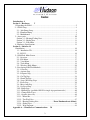
1-Unpacking the SOLO
•
•
Remove all material from inside the crate except for the SOLO itself.
Cut the Black plastic strapping that secures the SOLO to the shipping form.
Shipping
Straps
•
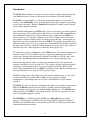
Once the straps are removed lift the SOLO by the aluminum bracket that the nest
plate holders are secured to. DO NOT LIFT BY THE ARM as this will damage
the unit. See Picture on next page
5
Lifting points
on Solo
•
Once the unit is out of the crate remove all the plastic wrapping that secures the
arm to the SOLO and the cooling nest to its alignment bracket.
Remove
Plastic Wrap
6
•
Once the plastic wrap is removed install the nest plates on the deck of the SOLO.
Align the holes in the bottom of the nest plate with the metal dowel pins on the
stainless deck and push the nest plates onto the deck.
•
Remove the Power cable and communication cable from their shipping packages
and plug them into the correct locations on the SOLO’s rear panel.
Install the SOLOSoft on the computer you are going to use with the SOLO.
The unit is now ready to startup.
•
•
7
2 – SOLO Setup
Depending on the version of SOLO that you purchased, there will be different hardware
setups before you start using your instrument. We currently carry three types of SOLOs:
1-Ivek Pump (125ul or 250ul)
2-Hamilton Pump (syringe size optional)
3-MultiChannel (8 or 12 Channel configuration)
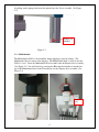
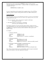
2.1 – Ivek Pump Setup
The Ivek Pump SOLO comes ready to run from the factory. The Mandrel is shipped on
the unit, so there is no need to setup anything on the unit. (See Figure 2.1)
Unit ships with
mandrel installed
Figure 2.1
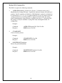
2.2 – Hamilton Pump
The Hamilton pump SOLO is disassembled during shipping to prevent damage. The
glass syringe from the pump is removed before shipping. The mandrel for a disposable
tip, or the fixed cannula tip, is also removed before shipping. You may need to home the
unit first before you can reinstall the Glass syringe. The cannula tip mandrel is installed
8
be pulling out the plunger that locks the mandrel into the Z-axis assembly. (See Figure
2.2)
Plunger for
mandrel
Figure 2.2
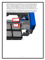
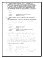
2.3 – Multichannel
The Multichannel SOLO is disassembled during shipping to prevent damage. The
Multichannel head is removed for shipping. The Multichannel head is screwed onto the
SOLO’s z-axis. Screw the Multichannel head assembly onto the Pipettor drive assembly.
(See Figure 2.3) You will do this by screwing the Blue threaded nut that is attached on
top of the Multichannel head to the Threaded post on the Pipettor drive assembly. (See
Figure 2.4)
Threaded
Nut
9
Figure 2.3
Figure 2.4
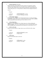
After the Multichannel head is installed onto the SOLO, you must install the Pipettor
Latching Bracket onto the assembly. Slide the bracket onto the Multichannel head and
line up the mounting holes for the bracket with the mounting holes on the Pipettor
assembly. Use the supplied thumbscrews to attach the bracket to the Pipettor assembly.
(See Figure 2.5)
Thumbscrews for
bracket
Pipettor Latching
Bracket
Figure 2.5
3 – Accessories
The SOLO has several options that can be purchased in additional to the SOLO they are
the following:
1- Heating/Cooling Nest
2- Shaker next
3- SOLOPlus (SOLO w/attached Micro10x)
10
Section 3.1 – Heating/Cooling Nest
The Heating/Cooling Nest accessory comes pre-attached onto the SOLO chassis. The
power and communication cables are not attached to the unit when it is shipped. Remove
them from the shipping crate and install them on the Cooling/Heating Nest. (See Figure
3.1)
Figure 3.1
Section 3.2 – Shaker Nest
The Shaker Nest comes shipped separately from the SOLO. The Shaker Nest has the
same alignment holes that are located in the standard nest plates. To install the Shaker
Nest, remove on the nest location and install the Shaker Nest in that location. Plug in the
supplied power/communication cable into the Shaker Nest. Plug the communication
cable into an available comport on the computer.
Section 3.3 – SOLOPlus
The SOLOPlus option is the addition of a Hudson Robotics, Inc. Micro10x reagent
dispenser that is attached to the side of the SOLO (See Figure3.2). The SOLO is
equipped with an alignment bracket that is attaches the Micro10x to the SOLO chassis.
This alignment bracket can be mounted in the front position of the SOLO, so that the
Micro10x nest is located at the SOLO deck position 6, or in the back position, so that the
Micro10x nest is located at the SOLO deck position 5. This bracket contains two
11
alignment pins which locate the Micro10x into its proper position. During shipping the
SOLO and Micro10x are shipped in different boxes. To install the Micro10x onto the
SOLO, you will slide the Micro10x next to the SOLO where the alignment bracket is
installed. Slowly lift the Micro10x up, so the bottom of the plastic deck is above the
alignment pins. Move the Micro10x into position, so that the alignment holes in the
Micro10x plastic deck are aligned with the alignment pins in the SOLO bracket. Slowly
move the Micro10x down until the Micro10x deck is located on the pins, and that the
bottom the Micro10x deck is sitting flush on the alignment bracket. You may have to
adjust the feet on Micro10x to re-level the unit to the SOLO deck. (See Figure 3.3)
MC10X Plastic
Deck with
Alignment holes
SoloPlus
Alignment
Bracket
Figure 3.2
12
Figure 3.3
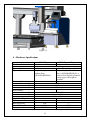
4 – Hardware Specifications
SOLO Pipettor
Hardware features
Arm configuration
Tip configuration
Tip variety
Positioning Precision:
X-axis
Y-axis
Z-axis
Motion Range
X-axis
Y-axis
Z-axis
Liquid handling features
Pipetting
Bulk Dispensing
No of fluid sources
Syringe size
SOLO Pipettor/Dispenser
One liquid handling arm
1 disposable tip
1disposable tip/Pipetting Needle
Disposable tips with or
Disposable tips with or without
without filters
filters (10,20,50,100,250 µL) or
(10,20,50,100,250 µL)
Stainless Steel Pipetting Cannula,
various gages and length are
available.
± 0.025mm
± 0.025mm
± 0.004mm
594mm (23 3/8")
244mm (9 5/8")
101mm (4")
٧
N/A
N/A
125, 250µL
13
٧
٧
1,3,5,7
µL
Wash Pump
Safety features
Password protection
Emergency Stop
Dimensions
Weight
Power requirements
Operating conditions
Regulatory compliance
Computer requirements
N/A
Delivery of wash solution by
peristaltic pump.
Flow: 7,14,21,28 mL Software
adjustable.
E-stop Button located on the front of the dispenser chassis
W. 556mm (30") x D. 483mm (19") x H. 610mm(24")
27 kg (60 lb)
Power: 60VA Voltage: 100-240VAC, Frequency: 50/60HZ
Temperature 15-32°C/ 59-90°F, Relative humidity 30-80%
(non condensing)
PC with Microsoft Windows XP or Microsoft Windows7
Intel Pentium 4 or AMD equivalent.
Free disk space 25 MB
RAM : 512kB
1 RS232 port or 1 USB port
SOLO Multichannel
Hardware features
Arm configuration
Tip configuration
Tip variety
Multiple liquid handling arm
12 or 8 Channel Disposable tip
Disposable tips with or without filters
(20 or 200 µL)
Positioning Precision:
X-axis
± 0.025mm
Y-axis
± 0.025mm
Z-axis
± 0.004mm
Motion Range
X-axis
594mm (23 3/8")
Y-axis
244mm (9 5/8")
Z-axis
101mm (4")
Liquid handling features
Pipetting
٧
Bulk Dispensing
N/A
No of fluid sources
N/A
Syringe size
20 or 200 µL
Wash Pump
N/A
Safety features
Password protection
Emergency Stop
E-stop Button located on the front of
the dispenser chassis
W. 556mm (30") x D. 483mm (19") x
Dimensions
H. 610mm(24")
27 kg (60 lb)
Weight
14
Power requirements
Operating conditions
Regulatory compliance
Computer requirements
Power: 60VA Voltage: 100-240VAC,
Frequency: 50/60HZ
Temperature 15-32°C/ 59-90°F,
Relative humidity 30-80% (non
condensing)
PC with Microsoft Windows 2000 or
Microsoft Windows XP
Intel Pentium 4 or AMD equivalent.
Free disk space 25 MB
RAM : 512kB
1 RS232 port or 1 USB port
15
Section 2 – Software
1-Installation
1.1 – Installation CD
Place the SOLOSoft Installation CD in your CD drive. It will automatically begin
the Installation process. It will create a folder “C:\Program Files\ SOLOSoft”
where the SOLOSoft executable files, the SOLOSoft Active X control, plate
definition Access database and support files are loaded. This folder is also the
default folder for all SOLOSoft methods, which have the file extension “.hso”.
Several sample methods are loaded from the CD as well.
1.2 – RS-232
Most users will choose to use the included RS-232 cable to connect their
computer to the SOLO. If you are using RS-232, a 9-pin female RS-232
connector is located on the rear panel of the SOLO. Connect the provided cable
here and to the serial port on your computer. Selecting the serial port assignment
and communication parameters is covered in another section of this manual.
16
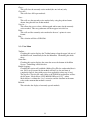
2 – SOLOSoft: Main Screen
2.1 - Overview
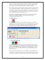
Upon Startup, SOLOSoft presents the ‘Log In’ display, which shows the
current Version and a “Log In” button. Click on the button, then enter
your name and password. On initial usage, the default User Name is “Me”
with a NULL password. Under the “Tools Menu” discussion below are
instructions about setting up actual user names and their passwords.
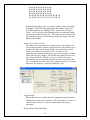
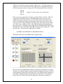
After entering a valid user name and password, the ‘Main Screen’ display
is shown, as below:
Clicking on any of the five options on the Menu Bar provides the menu
features described in the following subsections.
2.2 – File Menu
New –
This option creates a blank method whose default name is “Document1”,
and the user can now start developing a new method as described in the
‘Method Development’ section below. For SOLOPlus units equipped with a
multi-channel pipetter, a message box with the question “Do you want to use
‘Single Tip Mode?” will appear on the screen. Selecting ‘Yes’ as an answer,
will instruct all steps in the new method to use only one channel of the multichannel pipetter head. The new method can then be saved under the “Save
As…” option described.
Open –
This option allows the user to open an existing method, either to run it or to
edit it. The default storage folder for existing methods is “C:\Program
Files\SOLOSoft”, however a browse window allows the user to for a method
file that may be located elsewhere. Multiple methods may be open at the
same time, with the currently active method being the one whose display is
out front.
17
Close –
This will close the currently active method (the one in front) only.
Close All –
This will close ALL open methods.
Save –
This will save the currently active method only, using the path and name
shown along the title bar of that method.
Save As… This allows the user to select a different path and/or name for the currently
active method. This new path.name will then appear in its title bar.
Print –
This will send the currently active method to the user’s printer in a text
format.
Exit –
This selection will close SOLOSoft.
2.3 – View Menu
Toolbar –
Checking this option displays the Toolbar buttons along the upper left area of
the Main Screen, immediately below the Menu Bar. Unchecking this hides
these.
Status Bar –
Checking this option displays the status bar across the bottom of the Main
Screen. Unchecking it hides this bar.
Enable Logging –
Checking this option will establish a Method Log File for each method that is
run. Every step executed by the method will have its date and time of
completion logged, along with process data applicable to that step (if any).
The log file is saved in the same folder as the SOLOSoft application, and has
the file name “MethodName YYYY-MM-DD HH-mm-SS.log”, where
MethodName is without the “.hso” extension, and the date/time in the name
refers to the moment that method is started.
Refresh –
This refreshes the display of currently opened methods.
18
2.4 – Tools Menu
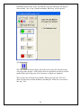
Simulated Configuration –
This option is only active when the communications port (see
Communications…, below) is set to <none>, forcing SOLOSoft into Simulate
Mode. This allows the user to try out different SOLO configurations, such as
switching between ‘P’, ‘D’, ‘P8’ and ‘P12’ syringe configurations, changing
syringe volume, and switching from Landscape to Portrait layout:
System Liquid (not applicable to simulation mode)
a. ‘P’ Syringe Type (Z-axis mounted syringe) –
This option allow the user to move the syringe piston Up (Aspirate) or
Down (Dispense) where only the syringe piston moves, not the robot axes:
Aspirate – the user can enter a volume (uL) , or by leaving the volume at
“FILL”, run the syringe piston all the way to the top of its stroke.
Dispense - the user can enter a volume (uL) , or by leaving the
volume at “EMPTY”, completely empty the syringe by running the
syringe piston all the way to the bottom of its stroke.
19
b. ‘D’ Syringe Type (Side-mounted valved syringes) –
This option allow the user to move liquid from any of the systems fluid
reservoir vessels to or from the tip. For both Aspirate and Dispense, the
reservoir is selected by selecting the appropriate Valve Port in the
displayed input box:
Aspirate – the user can enter a volume (uL) to move from the tip to the
reservoir (even volumes greater than the syringe’s volume), or by
checking the ‘Continuous’ operation box, run the syringe piston
continuously until the user clicks on the “Halt” button. The ‘No.
Strokes’ box can be checked and the desired number of aspiration strokes
entered as another operation option. If there are multiple syringe pumps
on the SOLO, the Syringe box will drop down to allow the user to select
any individual syringe or, at the bottom of the list, “ALL” syringes
operating together.
Dispense – the user can enter a volume (uL) to move from a reservoir to the
tip (even volumes greater than the syringe’s volume), or by
checking the ‘Continuous’ operation box, run the syringe piston
continuously until the user clicks on the “Halt” button. The ‘No.
Strokes’ box can be checked and the desired number of dispensing
strokes entered as another operation option.
20
Calibrate Deck… –
This option allows the user to create, teach, save or delete robot positions
within the working area of the SOLO’s 3-axis robot arm, as well as to jog the
arm within that work area. Clicking this option will produce the following
screen display:
The first 8 position names in the list are PERMANENT and cannot be deleted,
however, the user can re-locate them anywhere within the work area of the
robot, however they are intended to be located properly for use in the SOLO’s
plate nests and tip shucking/flushing stations as follows:
Position1 – the lefthand rear plate-nest location. It should be
programmed with a disposable tip pressed onto the syringe tip mandrel
(in the case of a SOLO with this option), or using the fixed tip. It is
intended to be programmed in the exact center of well ‘A1’ of a 96-well
plate located in that nest position (‘A1’ being located in the rear left
corner of the plate-nest for Landscape layouts, in the right rear corner of
this nest for Portrait layouts). Upon clicking the “Save Point…” screen
button, SOLOSoft will save this point name with the current X- and Yaxis coordinates, and set the Z coordinate equal to the Z-axis’ current
‘travel height’ setting. This Z-axis setting applies to all 4 (or 6, for
Portrait layout) of the plate-nest positions listed here.
Position2 – the lefthand front plate-nest position.
Position3 – the middle rear plate-nest position.
Position4 – the middle front plate-nest position.
Position5 – the righthand rear plate-nest position.
Position6 – the righthand front plate-nest position.
Flush – located with the tip in or above the waste drain fixture.
21
TipDisposal – located where the syringe tip is within the tip-stripping
fixture, with the forks of the fixture surrounding the syringe tip mandrel,
and just above the top of a disposable tip so that an upward movement of
the robot will strip off the disposable tip.
The coordinates of any position selected from the list along the left will be
shown in the box entitled “Position Coordinates(steps)”. The user can directly
modify these coordinates, then move to the modified coordinates. However,
the actual saved coordinates of that position will NOT be overwritten unless
the user clicks on the “Save Point at Current Location” button on the right.
The screen button “Set Skew” allows the user to adjust the calculated locations
of plate wells in case an individual nest is not in perfect alignment with the Xor Y-axes. Pressing this button when teaching a plate nest position will
provide the user with instructions on how to make this adjustment. This is
important particularly when dealing with 1536-well plates.
The screen button “Relax Motors” can be used to remove power from all 3
robot axes, allowing the user to manually maneuver the tip to the desired
location. Clicking on that button again will restore motor power.
Change Password…This allows the current user to change his/her password, which will then apply
to any subsequent log-ins.
Users… –
This allows a user of Level 3 to add or delete users from the system’s database.
Login… This allows the user to login using his/her User Name and Password. The User
Level will become that of the newly logged-in user.
Notes on User Level Restrictions:
User Level 1: Intended for users who can operate the SOLO but are not
allowed to open, change, save or close methods, or use the
Communication utility. Level 1 users can run already loaded
methods, teach/modify deck positions and change their own
passwords.
User Level 2: Level 2 users cannot create new methods, add or delete users,
or use the Communications utility. All other SOLOSoft
functions are available to Level 2 users.
User Level 3: All SOLOSoft functions are available to Level 3 users.
22
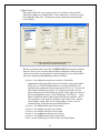
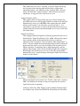
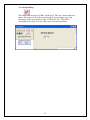
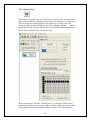
Define Plate Types… This enables the user to define the properties of the various microplates that
will be used in the SOLO. The following screen is displayed:
The user creates a new plate by placing the mouse cursor in the last row of the
“Name” column, then typing in the name of the new plate. The user must also
enter the number of “Wells” (the SOLO will calculate the center of each well
based upon this), the “Height” of the top of the plate from the nest surface,
then the depth of the bottom of the plate’s wells, measured from its top
surface. This “Max Depth” depth will be limit below which the SOLO needle
or disposable tip will not travel when aspirating or dispensing within a
SOLOSoft method.
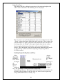
Defining Disposable Tip Boxes and Tips:
When
defining
disposable
tip box
parameters,
the “Height”
value should
be
the height
of the top of
the
disposable
tip, as it
rests in the
tip box,
above the
surface of
the plate
nest. The “MaxDepth” value should be the length of the
disposable tip (shown as ‘Tip Length’ in the sketch below), measured from the
shoulder of the tip mandrel to the end of the tip, when it has been picked up
using a SOLOSoft method’s “GetTip” step:
23
This data is saved in an ACCESS database table “C:\Program
Files\SOLOSoft\SOLOSoft.mdb”. This must be opened directly if the user
wishes to delete a plate type.
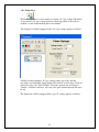
Communications… This enables the user to select the type of communication to be used by the
computer (Serial or TCP/IP), select the RS-232 port (if applicable) or the IP
address of the SOLO. The following screen is displayed:
The ‘Terminal Window’ button provides a HyperTerminal window which will
use the Serial port selected in the ‘Communications Port’ list box to enable the
user to use the SOLO’s ASCII Command Set (see Appendix A). The user can
then issue commands directly to the SOLO from the computer keyboard.
24
Shaker Nest Accessory:
If the SOLO has the Shaker Nest Accessory, the user would setup the serial
port to control the shaker using the Shaker tab in the Communications display
form:
Micro10x Accessory:
If the SOLO has the Micro10x Accessory, the user would setup the serial
ports to control the Micro10x and (if equipped) Ten Way Valve using the
‘Micro10’ tab in the Communications display form:
25
2.5 – Window / Help Menus
The Window menu enables the user to manipulate the window display patterns
familiar to users of MicroSoft Windows products. The Help menu’s ‘About’
option will show the current version of SOLOSoft.
26
3 – Developing SOLOSoft Methods
3.1 – Overview
SOLOSoft enables the user to create, save and run pipettor processes called
‘methods’. A method consists of a series of sequential actions, called ‘steps’, that
the SOLO will execute when that method is run. Methods are created and
modified using a “drag and drop” editor that is started when the user opens a new
method or an existing one, using the File Menu described above. Using the File
Menu to select the “New” option will display the following screen:
The user adds each desired method step by “dragging” any of the ‘Step’ buttons,
in the toolbar at the upper left, into the white field immediately below, arranging
the steps in the order desired by the user. As each step is “dropped” into the
white field, the grey area to the right will provide a GUI specific to that type of
step that allows the user to define parameters for that step. A completed method
will consist of a series of steps arranged in a single vertical column, much like a
flow chart. Step types available to the user are described below.
27
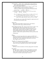
3.2 – Aspirate Step
This step will move the pipettor to a selected aspirate position, then aspirate the
indicated volume of fluid. The display shown below depicts an Aspirate step
drawing 95 uL from well ‘A3’ of a 96-well plate located at Position1 on the
SOLO’s deck on its first execution, then 75 uL from well ‘C4’ on its second
execution (see the LOOP step below):
The user has a number of parameters to select in an Aspirate step:
Select Type of Source –
Plate Position: A ‘Plate Position’ can be selected and identified by
clicking on one of the 4 possible deck plate-nest positions (Position1
to Position4) in the deck image above the selection box.
‘Named’ Point: if this is selected, the screen will change to that shown
at the end of this subsection below, allowing the user to select ANY
taught position, whether or not associated with a plate-nest. The
available points are selected from a drop-down list shown near the
bottom center of the display, and the user would enter the desired
volume in the box immediately above this.
28
Increment Order – (applies only to aspirating from a plate position for
SOLO equipped with single tip pipettor head or multi-tip pipettor
head used in ‘Single Tip Mode’)
Row Order (disabled for multi-tip option of ‘P8’type syringe) : If a
multiple number of wells per execution is entered, or
if this step is within a Loop, each aspiration will increment in the
order “A1, A2, …. , A12, B1,…, B12, etc.”.
Column Order(disabled for multi-tip option of ‘P12’type syringe):
“A1, B1, … , H1, A2, …, H2, etc.”.
Note: For multi-tip ‘P8’ syringe all non-zero volume wells in each
row will be addressed before moving to the next row.
Note: For multi-tip ‘P12’ syringe all non-zero volume wells in each
column will be addressed before moving to the next column.
Any wells with a zero volume will be skipped by single-tip units and
not included in the increment count.
Syringe (uL) –
This is read from the SOLO’s firmware and is selected from a
dropdown list of the syringes actually on this unit.
Start by Emptying Syringe (‘Pn’ syringe type only, where n is 0,1,8 or 12)
Checking this box will cause the needle or tip to move over the
intended aspirate position, then the syringe piston will move to its
bottom (empty) position at the start of this step. This is useful to
ensure that the full capacity of the syringe is available for this
aspiration. Otherwise the aspiration will start at the last position of the
syringe piston.
Mixing –
If the box is checked, immediately after aspiration, the SOLO will
dispense then aspirate the amount entered the number of times given by
the ‘Mix Cycles’ value, ending with a final dispense to leave the
mixed sample in the well or vessel.
Valve Port (‘D’ syringe type only, not shown) –
The user must select the appropriate fluid reservoir by choosing the
correct valve from a drop down list for the selected syringe pump.
Syringe Speed –
Scroll up or down to accelerate or slow the syringe piston’s movement.
Pre-Aspirate –
Enter this volume to aspirate air before each aspiration event in this
step. This allows air pockets to separate each individual aspirated
sample, and also allows the dispense volume to “blowoff” with
an air pocket to forcibly expel tip droplets at the end.
29
Backlash –
Enter the number (the default is 0) of uL that you wish to have the
syringe piston move in reverse at the end of its stroke. This is used to
control droplets or end-of-tip air gaps (also used in a Dispense step) for
a given commanded volume.
Multiple Wells –
The number of aspirations done in each execution of this step, in the
selected row or column order. Any wells with a zero volume will be
skipped and not counted in the number selected.
Note: For multi-tip ‘P8’ only column order is available and for ‘P12’
syringe only row order is available .
Switch to File Data –
If the ‘Switch to File Data’ option is selected, the user will be
shown a browse screen to browse for the file or to just enter its name.
The selected file and its path will be shown just below the button’s
location. The text on the button will change to “Switch to Entered
Data” to enable the user to go back to using the plate image table
across the bottom of the display, and manually enter volume values for
each well or the named point. The file structure will be determined by
which type of position is to be aspirated from:
Aspirate from Plate Position:
The volume to be aspirated from each well can be imported from a
comma-separated text file with a row/column format that matches the
plate type selected for this position (e.g., 8 rows of 12 values each for a
96-well plate). This file lists each row on a separated line, with each
column’s value separated by a comma, resulting in a file similar to that
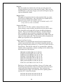
shown below for a 96-well plate:
50,58,66,74,82,90,98,106,114,122,130,138
51,59,67,75,83,91,99,107,115,123,131,139
52,60,68,76,84,92,100,108,116,124,132,140
53,61,69,77,85,93,101,109,117,125,133,141
54,62,70,78,86,94,102,110,118,126,134,142
55,63,71,79,87,95,103,111,119,127,135,143
56,64,72,80,88,96,104,112,120,128,136,144
57,65,73,81,89,97,105,113,121,129,137,145
The file for a 384-well plate would have 16 rows of 24 values each.
For multi-tip operation only values for wells addressed by first tip of
multi-tip head are taking in consideration. Tips on the head are
counted from left to right. See bellow file list for aspirating with 12
tip head (‘P12’) from 96-well plate:
50, 50, 50, 50, 50, 50, 50, 50, 50, 50, 50, 50
42, 42, 42, 42, 42, 42, 42, 42, 42, 42, 42, 42
30
0, 0, 0, 0, 0, 0, 0, 0, 0, 0, 0, 0, 0
0, 0, 0, 0, 0, 0, 0, 0, 0, 0, 0, 0, 0
0, 0, 0, 0, 0, 0, 0, 0, 0, 0, 0, 0, 0
0, 0, 0, 0, 0, 0, 0, 0, 0, 0, 0, 0, 0
20, 20, 20, 20, 20, 20, 20, 20, 20, 20, 20, 20
10, 10, 10, 10, 10, 10, 10, 10, 10, 10, 10, 10
Well positions that have zero (or negative) volume values will simply
be skipped. The SOLO will aspirate from the number of non-zero
wells determined by the “Multiple Wells” setting, then, if inside a
“Loop” , will start at the well following the last one aspirated during
the previous execution of this step. The volumes to be aspirated will
appear in their respective well locations in the plate image across the
bottom of the display.
Aspirate from ‘Named’ Point:
The volume to be aspirated from a point, such as a vial location, can
also be imported from a comma-separated text file, but for this type of
position, the values can be in any number of rows/columns, and are
read in left-to-right, top-to-bottom order. As in the case of
aspirating from a plate position above, any zero (or negative) volume
values will simply be skipped. The SOLO will aspirate the next nonzero volume in the file. If inside a “Loop”, it will use the value
following the last one aspirated during the previous execution of this
step. A complete list of the values to be aspirated can be viewed in the
dropdown’ list inside the “Aspirate Volume(uL)” box.
Aspirate Shift –
This enables the user to adjust the actual aspiration location from the
taught position selected for aspiration. This enables the user to go to a
‘non-standard’ location, or to move in other than well-spacing
increments.
Do Tip Touch / Tip Touch Shift –
31
This enables the user to do a ‘tip touch’ to clean a droplet off the tip,
and to specify where that tip-touch will be relative to the actual
aspiration location. Any shift done in the ‘Aspirate Shift’ selection
above will affect this ‘aspirate location’. This will cause the tip to
touch twice, on opposite sides of the well or vessel.
Aspirate Volumes (table) –
This graphic shows an image of the plate type selected for this step,
and enables the user to enter distinct volumes for each well in the plate.
(Important: be sure to pres <ENTER> after entering the last volume
into any well location, as it will not be saved if you don’t!). As a
convenience, you may enter a value in the first element of any row or
column, then click on the row/column number to set every well in that
line to that value.
Liquid Level Detect –
Units equipped with the Liquid Level Sensing option allow the user to
check the box “Liquid Level Detect” box, which will cause the pipette
tip to seek the surface of the liquid in the well or vessel being
aspirated. If this is checked, a text box labeled “Max. Depth (mm)” is
shown. The user should enter the maximum depth of the tip below the
upper rim of the well or vessel, below which it will not proceed if no
liquid is detected. If aspirating from a defined microplate, and the
entered “Max. Depth” value exceeds the Plate Depth value, that plate’s
Plate Depth value will be used, so as not to drive the tip beyond the
bottom of the well. A typical display showing the Liquid Level Detect
feature is shown below:
When using liquid level detection, the “Z-shift” value in the “Aspirate
Shift” box indicates the distance to move the tip below the detected
liquid level prior to aspirating.
If the tip reaches the “Max. Depth” position without detecting liquid,
the Aspirate step will end and SOLOSoft will perform its next action.
32
3.3 – Dispense Step
This step will move the pipettor to a selected dispense position, then dispense the
indicated volume of fluid. The display shown below depicts an Dispense step
expelling 80 uL into well ‘A2’ of a 384-weel plate located at Position4 on the
SOLO’s deck on its first execution, then 75 uL into well ‘C4’ on its second
execution (see the LOOP step below):
The parameter selections are identical to those of the Aspirate step, except for the
following:
Do High-Speed Dispense – If this box is checked, this step will advance
between each of multiple dispenses in the step without descending
into the well, saving time by avoiding that motion. ‘Tip-Touch’ is not
available if this option is selected.
Mixing – Same as Aspirate step, except in opposite order, but ends with a
dispense as well.
Blow-off – This amount will be expelled from the syringe after the last
‘dispense’ amount in this step is released. It is used to blow off a
droplets that may be on the tip at the end of dispensing.
33
3.4 – Get Tip Step
This step, whose GUI is shown in the next figure, will start by shucking any tip
that may have been left on the mandrel from a prior activity, then move to the
next tip position in a tip box located at, in this example, Position1:
As in the Aspirate step, the location of the tip box is selected by clicking on the
appropriate nest position in the displayed deck image. For syringe types ‘D’ and
‘P0’ the tip shucking executed at the beginning of this step will occur at the
position selected in the “Select Disposal Point” box. For syringe types ‘D’ and
‘P0’ below the deck image is a note showing the tip location inside the tip box
where the last tip was used. For all syringe types SOLOSoft keeps track of tip
count in tip boxes between methods and even if closed and powered-down. For
syringe types ‘D’ and ‘P0’ the tip retrieved in this step will be the next tip in the
box, counted across the box in ‘row order’. For multi-tip syringe types ‘P8’ and
‘P12’ SOLOSoft keeps track of tips available in tip box for box single-tip and
multi-tip operations.
The “last tip” count will be reset to zero if the type of plate at that location is
changed, if the identity of that tip box is changed (e.g., if operated using Hudson’s
SoftLinx scheduling software and a new tip box is moved into that position), or if
the tip box is reset in the “Change Plate Types” utility (see that subsection
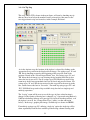
below). In the step’s graphic plate image, available tips are shown in GREEN.
For multi-tip syringe type ‘P8’ utilizing ‘single-tip’ option the single tip will be
taken sequentially from the first available position along columns starting with
34
column 1 and row H progressing in direction from row H to A and then columns
from 1 to 12. In case of using ‘multi-tip’ option, 8 tips will be picked up from
first available column in the box filled with tips starting with column 1.
For a multi-tip syringe type ‘P12’ utilizing ‘single-tip’ option the single tip will be
taken sequentially from the first available position along rows starting with row A
to row H progressing in direction from column 12 to 1 and then rows A to H. In
case of using ‘multi-tip’ option, 12 tips will be picked up from the first available
in the box filled with tips row starting with row A.
For guidance on programming tip pickup positions and using different length
disposable tips in different methods, see the subsection below entitled
“Programming with Disposable Tips”.
3.5 – Shuck Tip Step
This step, whose GUI is shown in the next figure, allows the user to discard a
disposable tip at the position indicated in the “Select Disposal Point” box. This is
usually used at the very end of a method to strip off a remaining tip. Otherwise,
the “Get Tip” step is normally used to shuck a tip prior to getting another.
3.6 – Loop / End Loop Steps
These steps, shown in the next figure at the top and bottom of the method flow
diagram, allow the user to repeat sequences of steps the number of times indicated
in the “Enter NUMBER of Loops to Perform” box. After repeating every step
between these two loop steps, the method will continue with the next step after
the ‘End Loop’ step.
Loops can be nested within other loops. If, for instance, a loop with 3 repeats is
nested inside a loop with 2 repeats, the steps inside the inner loop will be executed
a total of 6 times, while those within only the outer loop will be executed 2 times.
35
SOLOSoft will pair each ‘Loop’ step with the very next ‘End Loop’ that appears
in the method. Any ‘Loop’ without a matching ‘End Loop’ will be ignored.
3.7 – Pause Step
This step, shown in the next figure, allows the user to pause the run and present
a message to the operator. It also allows the user to permit the operator to end the
method at the time of the pause (if, for instance, no liquid was aspirated).
The user types the desired message into the “Enter pause message” box, and
allows the operator to end the method by checking the “Allow user to end run at
this step?” box.
36
The user may also simply set a timer (in seconds) to pause the method here, then
automatically resume after the time has elapsed.
3.8 – Move Arm Step
This step, shown in the next figure, allows the user to simply move the robot
arm to any taught position at a speed given as a percentage of the arm’s full
speed in the “XYZ Speed” box. The ‘X’ and ‘Y’ axes move first, followed by
the ‘Z’ axis.
As an option, by checking the “Move ‘Z’ Axis…” box, the tip will move up to its
normal travel height prior to moving laterally to the selected destination position.
37
3.9 – Set Speed Step
The default robot arm speed is 100% of full speed. This step, shown in the next
figure, allows the user to set the movement speed for subsequent steps at the
percentage of full speed depicted in the “XYZ Speed” box. This will be
overridden by the value set in any “Move Arm” step that may follow.
38
3.10 – Prime Step
The Prime step allows a user to prime or evacuate “D” type syringe liquid lines,
or to position a “P” type syringe piston at a desired position, at the start of a
method, or even at intermediate places in a method.
The display for a SOLO equipped with a “D” type syringe appears as follows:
A SOLO can have multiple “D” type syringe pumps (up to 10), and this
step allows any individual syringe pump to be exrcised, or all at once. If all are
exercised at once, the “Total Volume” selection is greyed-out, and only the
“Strokes” selection is allowed. Also, the valve port selection must be the same
for all.
The display for a SOLO equipped with s type “P” syringe appears as follows:
39
The user make elect to position the syringe piston at the very top of its stroke
(FILL) or position it at the bottom of its stroke (EMPTY). Alternatively, the
syringe may be moved by a selected amount (in uL), either up (Aspirate) or down
(Dispense).
3.11 – HitPick Step (available ONLY for single-tip operation modes)
The HitPick Step provides the user with a convenient way to consolidate the
contents of selected wells from one or more source plates into one or more target
plates. This step can be used for cherry-picking, rearraying and re-formatting
from one size plate to another. The HitPick step is setup much as if it were an
Aspirate Step and a Dispense Step combined into one. The user choices as to the
syringe selection, syringe speed, X,Y,Z offsets and Tip Touching are similar to
those in the Aspirate and Dispense Steps described above, and are not repeated
here. The user must select the Source plate’s position (out of the available plate
nest positions 1 through 4) and the target plate’s position. These selections will
also define the type of plate that will be present at each of these positions while
running, just as in the Aspirate or Dispense Steps above. The major differences
between the HitPick Step and the Aspirate or Dispense Steps are:
a. The Source plate’s data ALWAYS comes from a .CSV file, for which
the user selects the folder where the source file(s) will be found.
b. The Target plate’s information is derived from a “blocking” pattern
that is stored with the method.
c. The user selects an Output file and file path where the transfer
information is to be stored (the same file for all plates in a run).
There must be a separate source file for each Source plate, where that file’s name
is SourcePlateBarcode.csv. For instance, if that Source plate’s barcode is
40
“ABC123”, then the file’s name would be “ABC123.csv”. The file contents are
simply the well name of each source well, followed by a comma then the amount
(uL) to be transferred into each target well. The format would looks as follows:
A01,50
C09,75
H11,55
(each well,volume entry is on a separate line)
The user can use a header line, if desired, of “Source,Well” for clarity. This line
is ignored by SOLOSoft if present. The HitPick Step allows the user to fill
multiple target wells from each source well, and the amount aspirated from the
source well will be that multiple of the amount in the source file. That is, if the
user elects to fill 3 target wells from each source well, the amount aspirated from
well “A01” above would be 150 uL, with SOLOSoft multiplying the amount in
the source file by 3. Each line in the output file has the format “Date,Time,Source
Plate Barcode,Source Well,Target Plate Barcode,Target Well,Amount (uL)”, with
no header line. A typical entry would appear as follows:
6/23/2008,2:40:24 PM,ABC123,A03,DEF456,A01,53
The picture below shows the HitPick Step’s graphic image:
The user can select a Maximum Volume per Aspiration to allow the use of pipette
tips that may be smaller than the amount needed to complete the transfer, and may
set the number of Target Wells per Source Well. The SOLO will only aspirate up
to the Max. Volume each time. If more than one Target Well is to be filled per
Source Well, the SOLO will divide that maximum volume by the number of
41
target wells and dispense equal amounts in each until they receive the full amount
required. In order to reduce any effect from pipetting residual volumes at the very
lowest end of the pipette tip’s range, the next-to-last aspiration step will be limited
to 50% of the total remaining aspiration volume so that the last aspiration is also
at least 50% of the Max. Volume setting.
The user can browse the computer for the appropriate folder where Source plate
files will be found, and can browse or simply enter the full path and name of the
output file. Then, before saving the method, can select those Target plate rows,
columns or individual wells which will be blocked from receiving transfers from
the Source plate. These will be colored black as in the above graphic. The user
can also select whether to fill the Target plate in “Row” (across the top, then
down) or “Column” order. Pending but un-aspirated “hit” wells on the Source
plate are displayed in yellow, while completed transfers are shown in green on
both plates.
If the Source Plate’s “hits” have all been transferred, or if the Target Plate is full,
the HitPick Step will end, and, if this step is imbedded inside a Loop, that Loop
will end and the Method will proceed with the next step beyond that Loop’s
End Loop step. Usually, the Method will have been designed to end here to
enable replacing either of the finished plates.
Not shown in the graphic above are the aspiration and dispensing settings that the
HitPick Step has in common with the Aspirate and Dispense Steps, which are in
the lower portion of the HitPick Step’s graphic.
42
3.12 – GetLevel Step
The GetLevel step allows the user to detect and record, in a file, the liquid level
inside selected wells in a microplate located at one of the SOLO’s six plate nests.
The user begins by selecting the plate nest (and its type of plate) where the
microplate being measured will be located. Next, using the “Browse…” button
depicted in this step’s display (below), the user selects the location and name of
the file where the liquid level data will be saved.
The user should also select the “Search Speeds” (as percents of full speed) at
which the probe tip will descend to the liquid surface, and the speed at which the
syringe piston will expel air until the surface is reached. The user must then
43
select the number of wells to search (entering “-1” to select all unblocked wells),
the depth to which the probe should travel before stopping (that plate’s well
depth, as listed in its definition – see Define Plate Types… above - is the limit for
this setting), and the distance above the plate to begin the actual search.
The user would then select the order for incrementing the probe from one well to
the next (“Row” or “Column” order), and may block out individual wells of entire
rows or columns by clicking on the plate graphic at those wells or rows/columns.
Those wells thus appearing in BLACK will not be measured.
It is then up to the user to actually use the file data this step produces, such as in a
special VB step in SoftLinx or another external software application.
44
3.13 – Change Plate Types
This utility allows the user to select the type of microplate (or tip box, omni tray,
etc.) that is located in any of the 4 plate-nest positions. It also allows the operator
to reset any used tip box count to zero, which would have the SOLO start
retrieving tips at the ‘A1’ tip position.
To change a plate type at any of the 4 positions, or to add a plate where the nest
was empty, click on the ‘down’ arrow of the box for that position, and a list of all
the defined plate types in the SOLOSoft database will be shown. Clicking on the
desired plate will add it to that position. The ‘OK’ button will save the changes,
while the ‘Cancel’ button will restore the original data. These changes will take
effect immediately and remain so while this method is loaded. In order to
preserve these changes the next time this method is loaded, the method itself must
be saved upon closing it.
45
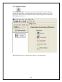
3.14 – Operate Accessory
This utility allows the user to operate any of several optional accessories that are
available for the SOLO. Drag down the ‘Operate Accessory’ button to select this
type of step. Then select the individual accessory by clicking on its icon button in
the display shown below:
The individual accessory selected will be shown as described below:
46
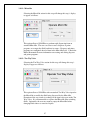
3.14.1 – Micro10x
Selecting the Micro10x action for this step will change this step’s display
to appear as follows:
This option allows a SOLOPlus to perform rapid dispensing from an
attached Micro10x. The user can select to run a dispense or prime
program, or to empty the fluid back into its source. Dispense and prime
programs are configured ahead of time in the Micro10x itself. Consult the
Micro10x manual for more information on creating and editing dispense
and prime programs.
3.14.2 – Ten WayValve
Selecting the Ten Way Valve action for this step will change this step’s
display to appear as follows:
This option allows a SOLOPlus with an attached Ten Way Valve input for
the Micro10x to modify the fluid being dispensed by the Micro10x.
Execution of the step results in a change in the input valve port on the Ten
Way Valve. It is recommended to re-prime the Micro10x after switching
fluids. Optionally, the user may want to empty the Micro10x before
changing fluid sources to conserve liquids.
47
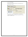
3.14.3 – Shaker Nest
Selecting the Shaker Nest for this step will change this step’s display to
appear as follows:
This enables the user to set the speed and duration of a shaking action for
the nest, if it is so-equipped.
3.14.4 – Wait For Input
Selecting the Wait For Input action for this step will change this step’s
display to appear as follows:
This option allows a suitably configured SOLO to pause here until a
digital input signal with the value of “Target Value” (1 or 0) is received
from another device, such as a robot or a user-operated pushbutton.
48
3.14.5 – Write To Output
Selecting the Write To Output action for this step will change this step’s
display to appear as follows:
This option allows a suitably configured SOLO to set a digital output
signal to the “Target Value” (1 or 0) to provide a signal to device, such as
a robot or a mechanical system.
49
Appendix A – Client/Server Communications
SOLOSoft allows other software applications (such as Hudson’s SoftLinx) to start
SOLOSoft methods and pass instructions and parameters to SOLOSoft via Windows
Sockets in a client/server arrangement.
Upon bootup, SOLOSoft establishes itself as a “server” in the clent/server setup. When
started, SOLOSoft attempts to establish a server port at port no. 11139. If successful, it
holds that port and can be connected via that port to any client application. If not
successful with port no. 11139 (such as when another instance of SOLOSoft is running),
this instance of SOLOSoft will advance the port number by 1, and retry. It will retry up
to 50 times, advancing the port number by 1 with each failure. If none of these 50 port
number succeeds, the error message “Cannot open TCP/IP Socket” will be displayed.
A client application can connect with SOLOSoft by attempting to connect over the same
socket port that SOLOSoft has opened, starting with11139, then advancing by 1 if this
fails until a connection is established.
Once a connection is established, a client application can send the following messages to
control and query SOLOSoft. Each command to SOLOSoft consists of a command string
ending in a binary 3 (ETX). SOLOSoft will send a reply containing the data requested
or, if no data is requested, SOLOSoft will send the string “0000<ETX>” to confirm a
valid command was received. The client application must then send the response string
“OK<ETX>”, which tells SOLOSoft the client has received SOLOSoft’s message. If the
client sends an invalid command, SOLOSoft will respond with “0001 Unrecognized
Command: <the commandstring it received><ETX>”. If a command has arguments, the
first argument is separated from the command by a space, while the individual arguments
are separated by commas. An illustration of the communication protocol is as follows:
SOLOSoft
Application
ADDPLATE Position1<ETX> 0000<ETX>
OK<ETX> 0001 Unrecognized Command: ADPLATE<ETX>
OK<ETX> ADPLATE Position2<ETX>
The invalid command contains a misspelling of the command itself.
50
Valid commands are listed below:
ADDPLATE PositionName[,PlateBarcode] - Tells the SOLO that a plate with a
barcode ID of PlateBarcode has been delivered to the SOLO’s deck at nest
PositionName. If PlateBarcode is omitted, just use PositionName and leave off the extra
commas.
CLOSE - Causes SOLOSoft to self-terminate.
GETMESSAGE – Obtains a string that the SOLO method creates at the end of a SOLO
method’s run. This value is nulled out upon being read via this command, and at the
beginning of any method run. It will contain either an error message, if the method ended
in an error condition, or will have the value “0000” if the Method ended successfully.
GETMETHOD - Obtains the name of SOLOSoft’s currently loaded, active method.
GETPATH - Obtains SOLOSoft’s current folder (where SOLOSoft.exe resides)
GETSTATUS - Obtains SOLOSoft’s current method’s running state: “IDLE”,
“RUNNING”, “PAUSED” or “STOPPING”.
GETTIPCOUNT PositionName - Gets the number of the last tip to be removed from a
tip rack at PositionName.
GETUSERPATH - Obtains the default folder where SOLOSoft methods and user data
files are stored.
GETVALUE VariableName, PositionName - Currently, the only VariableName
supported is “NESTSTATUS”, which returns the status of the SOLO’s PositionName
nest: “EMPTY” or “FULL”.
LOAD FullMethodPathName - Causes SOLOSoft to load the pre-saved method.
FullMethodPathName must contain the full path and file name (with extension) of the
method, which now becomes the currently active method.
PAUSE - Causes SOLOSoft to pause execution of the currently active and running
method.
RESUME - Causes SOLOSoft to resume execution of the currently paused method.
RUN FullMethodPathName - Causes SOLOSoft to load (if not already loaded) and run
the method FullMethodPathName (see LOAD above).
SETNAME – Allows the client application to give this SOLO unit a “name” that may
differentiate it from another SOLO that may be in the system. The default name is
"SOLO Pipettor".
SETNESTSTATUS – Sets the status of a SOLO’s plate nest position to enable the client
application to properly react to that status (such as “REMOVE” or “FULL”).
51
SETUP - Causes SOLOSoft’s window to expand to full size and the foreground.
SETVALUE VariableName, Index, Value - Enables the client application to set variable
values that SOLOSoft’s method will use. Four variable names are currently supported:
1. LOOPCOUNT, Index, Value: Enables the client to set the number of iterations of
LOOP step Index to Value in the current method. Index starts at 1 for the first
LOOP step in the method, and increments for each subsequent LOOP step, if
multiple LOOPs are present.
2. NESTSTATUS, Index, Value: Allows the client to set the status to Value
(“FULL” or “EMPTY”) of the SOLO nest at PositionIndex, one of the plate nest
names on the SOLO (e.g., “Position1”).
3. OUTPUTFILE,, FullPathName: Allows client to specify the full path and file
name (including file extension) of the output file to be used by any HITPICK step
in the current. This will override the file path/name that was saved with the
method. The second argument may be left blank.
4. SOURCEFOLDER,,FullPath: Allows the client to specify the folder where the
current method’s HITPICK step(s) will look for the input Source file, which is
always named PlateBarcode.csv, where the source plate’s barcode is input from a
different place in the application. FullPath must end in a backslash (“\”).
STOP - Causes SOLOSoft to stop the current running method, but leave it loaded and
current.
52
Appendix B – RS-232 Communications and Command Set
Firmware Version 7.00
Hudson's SOLO Single- or Multi- Channel Pipettor/Dispenser is designed to respond to a
simplified set of ASCII commands to allow any user program capable of reading/writing
via an RS-232 port or TCP/IP connection to exercise all the features of the SOLO.
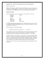
Protocol Description
The RS-232 connection for the SOLO operates with the following communication specifications:
Baud Rate:
Data Bits:
Stop Bits:
Parity:
Handshake:
Device Type:
Connector:
38400
8
1
None
None
DCE
9-pin, female
For TCP/IP communication, each unit must have a unique IP address assigned. This can
be accomplished with the SETIPADDR command. The computer should then connect to
this IP address on TCP port 7.
SOLO commands have the following format:
{command} {parameter1},[{parameter2}],…,[…]<13><10>
The {command} portion is the actual command to be executed by the pipettor. This may
be followed by a comma-separated list of parameters as specified in the individual
command descriptions. Arguments listed inside square brackets ([…]) are optional.
All SOLO commands are terminated by a carriage return / line feed combination (ASCII
characters 13 and 10). The command is then delivered to the pipettor unit, which parses,
validates, and executes the requested command before returning a response. Commands
may be sent to the SOLO while it is processing other commands. The SOLO can queue
up to 10 commands. The behavior when the queue when overloaded is currently
unspecified. There is currently no message indicating that the command queue has been
overloaded.
53
The following example would send the DISPENSE command, with an argument
indicating to dispense at position “Plate1”, a volume of 10 uL, at a syringe speed of 100%
of normal stroke speed:
DISPENSE Plate1,10,100<13><10>
A space is required between the command and its argument string. All are ASCII text
characters as shown (except the carriage return and line feed, which are binary bytes).
Command Responses
The controller will echo every byte of the command back to the sender as it is received. Upon detecting the
two bytes <13><10>, the controller will execute the command. Upon completing execution, the controller
will respond in one of two ways:
1. For query commands, where a data response is required, it will return:
{data response}<13><10>
2. For action commands or invalid queries, it will return:
{error code} {error description}<13><10>
If an action is requested, or an error occurs the response will be a 4 digit error code, a
space (ASCII character 32), and a short description of the error that occurred. A response
of “0000 Success" represents a correctly executed command. Other responses will
indicate an error.
As examples:
1. Valid query command:
Command:
GETPOS<13><10>
Echo:
GETPOS<13><10>
Response:
0,0,0<13><10> (i.e., current x,y,z coordinates)
2. Valid action command:
Command:
MOVE Position1<13><10>
Echo:
MOVE Position1<13><10>
Response:
0000 Success<13><10> (i.e., action successfully executed)
3. Invalid query command ("Washer" is an unknown position):
Command:
GETPOINT Washer<13><10>
Echo:
GETPOINT Washer<13><10>
Response:
0002 Invalid Parameter<13><10> (invalid point name)
Note: If any command contains an error, the StackLink sends the response immediately,
otherwise the response is sent at the completion of execution.
54
Hudson SOLO Command Set
The SOLO recognizes the following commands:
1.
ASPIRATE PointName, Volume (uL), [Speed (% of normal stroke speed)],
[Backlash (uL)], [Syringe ID letter]. Aspirates the indicated volume at the indicated
position. Speed is optional, and defaults to 100. Backlash is optional, and defaults to
0. Syringe letter (“a” or “b”, etc.) is required with the ‘D’ type of syringe if only one
syringe is desired to act and if the SOLO is equipped with more than one syringe
pump. Eliminating the syringe ID letter (or using a letter above ‘j’) will cause ALL
the syringes to obey the command. Syringe ID is only meaningful with the ‘D’
configuration.
Example:
Command:
Response:
2.
ASPIRATE Position1,50, 25,6<13><10>
0000 Success<13><10>
CLEARPOINTS
Clears all stored positions
Example:
Command:
Response:
3.
CLEARPOINTS<13><10>
0000 Success<13><10>
DELETEPOINT PointName
Deletes the position PointName
Example:
Command:
Response:
DELETEPOINT Position1<13><10>
0000 Success<13><10>
55
4.
DISPENSE PointName, Volume (uL), [Speed (% of full stroke speed)],
[Backlash (uL)] , [Syringe ID letter]. Dispenses indicated volume at the indicated
position. Speed is optional, and defaults to 100. Backlash is optional, and defaults to
0. Syringe ID (“a” or “b”, etc.) is required with the ‘D’ type of syringe if only one
syringe is desired to act and if the SOLO is equipped with more than one syringe
pump. Eliminating the syringe ID letter (or using a letter above ‘j’) will cause ALL
the syringes to obey the command. Syringe ID is only meaningful with the ‘D’
configuration.
Example:
Command:
Response:
5.
DISPENSE Position2, 50, 80,4<13><10>
0000 Success<13><10>
EMPTY [Volume (uL)], [Speed (% of full stroke speed)] (‘P’ configuration
ONLY)
Both arguments are optional. If none are given, the syringe goes to the bottom of the
stroke, otherwise it dispenses the given volume at the indicated speed. If speed
control is desired, but syringe needs to go to bottom of stroke, use “0” for Volume
and the desired setting for Speed. See FILL.
Example:
Command:
Response:
EMPTY 50,25<13><10>
0000 Success<13><10>
Or, to go to bottom:
Command:
EMPTY <13><10> or EMPTY 0,25<13><10>
Response:
0000 Success<13><10>
6.
EVACUATE [Volume(uL)], [Speed(%)], [Syringe ID letter] (’D’ configuration
ONLY)
All arguments are optional. The syringe will operate at the speed given (100 is
the default) until the specified volume is moved from the tip into the currently
selected reservoir. If no, or 0, Volume is specified, the syringe will continuously
move fluid (or air) from the tip into the currently selected reservoir, emptying the
line, and requiring a “HALT” command to stop the process. If a negative value is
given for Volume, the positive integer of that value will be the number of syringe
strokes to be executed, with the first stroke just bringing the syringe to the bottom of
its stroke. If Syringe ID is omitted, or if a syringe ID letter above ‘j’ is used, ALL
syringes will be operated together. See PRIME.
Example:
Command:
Response:
7.
EVACUATE 1000,25,b<13><10>
0000 Success<13><10>
FILL [Volume (uL)], [Speed (% of full stroke speed)] (‘P’ configuration ONLY)
Both arguments are optional. If none are given, the syringe to the top of the stroke,
Otherwise it aspirates the given volume at the indicated speed. See EMPTY.
56
8.
GETDECKHEIGHT [Position#]
Returns the distance (mm) of the deck surface of plate nest “Positionx” from the
shoulder of the mandrel at the Z-axis’ lower limit, and its calculated coordinate in
motor steps that would be the Z-position of the tip mandrel if it could reach the deck
surface of the plate nests. If the position # is omitted, the deck height at Position1 is
returned.
Example:
Command:
Response:
GETDECKHEIGHT<13><10>
25.5 mm, 33250 steps<13><10>
9.
GETDISPTIPCURRENT
Returns the LOW and HIGH Z-Axis running current range to use when performing
the GETTIP command. The current is adjusted linearly between the LOW and HIGH
values in proportion to how many tips are to be retrieved (1 to 12).
10.
GETDISPTIPSPEED
Returns the LOW and HIGH Z-Axis velocity range to use when performing the
GETTIP command. The speed is adjusted linearly in inverse proportion between the
LOW and HIGH values in proportion to how many tips are to be retrieved (12 to 1).
11.
GETFULLSTROKE
Returns the current number of stepper motor steps per full stroke of the syringe.
Example:
Command:
Response:
12.
GETFULLSTROKE<13><10>
3750<13><10>
GETIPADDR
Returns the current IP address of the unit.
Example:
Command:
Response:
GETIPADDR<13><10>
192.168.1.2<13><10>
57
13.
GETLAYOUT
Returns an ‘L’, for landscape (default), or a ‘P’, for portrait. ‘Landscape’ layout has
the plate positions arranged so that ‘A1’ is at the left rear corner of each plate, with
row ‘A’ running along the rear edge of the plate, from the user’s perspective facing
the SOLO. ‘Portrait’ has ‘A1’ at the right rear corner of the plate, with row ‘A’
running along the right edge of the plate. Immediately following the “L” or “P” is a
number indicating the number of nest positions this unit has on its deck.
Example:
Command:
Response:
14.
GETLAYOUT<13><10>
P5<13><10>
GETLEVELSENSING
Returns a ‘1’ if the level sensing option is installed and activated, a ‘0’ otherwise.
Example:
Command:
Response:
15.
GETLEVELSENSING<13><10>
1<13><10>
GETLIMITS
Returns the limits of each axis of motion. The limits are returned in the following
order: Xmin, Xmax, Ymin, Ymax, Zmin, Zmax
Example:
Command:
Response:
16.
GETLIMITS<13><10>
-500, 1250, -415, 4250, -4575, 20525<13><10>
GETPOINT PointName
Returns the saved position of the point name specified. The point’s motor step
coordinates are returned in X, Y, Z order.
Example:
Command:
Response:
GETPOINT Position1<13><10>
2148,-268,15874<13><10>
58
17.
GETPOS
Returns the current motor step position of the head in X, Y, Z order.
Example:
Command:
Response:
GETPOS<13><10>
2148,-268,15874<13><10>
18.
GETPUMPTYPE
Returns the type of pump drive (“PSD/2” or “PSD/4”) in a SOLO with a ‘D’ type
syringe.
Example:
Command:
Response:
GETPUMPTYPE<13><10>
PSD/4<13><10>
19.
GETSHUCKDEPTH
Returns the number of steps a MultiTip pipette head will travel beyond the ‘syringe
bottom’ when shucking disposable pipette tips.
20.
GETSIMULATEPUMP
Returns the current state of the pump. ‘0’ means the pump is active, ‘1’ means the
pump is in simulated mode.
21.
GETSKEW Position#
Returns the offset per mm of travel in both X-axis and Y-axis directions that the plate
nest at Positionx is out of alignment with that axis. The two factors are returned as
‘dX,dY’. The SOLO uses these to adjust the calculated position of the center of a
well in a plate at Positionx.
Example:
Command:
Response:
22.
GETSKEW 3<13><10>
0.00234,0.01658<13><10>
GETSPEEDS
Returns the assigned maximum speed for each motor. The speeds are listed X, Y, Z.
Example:
Command:
Response:
GETSPEEDS<13><10>
20000, 20000, 50000<13><10>
59
23.
GETSTEPSMM
Returns the number of motor steps required to move 1 mm for each axis, X, Y and
Z in that order.
Example:
Command:
Response:
GETSTEPSMM<13><10>
43.225,46.366,315.05<13><10>
24.
GETSYRBOTTOM (‘P’ configuration ONLY)
Returns the position in motor steps of the syringe’s bottom of stroke.
25.
GETSYRCOUNT
Returns the number of syringes on the SOLO (meaningful in ‘D’ configuration
only). Default value is 1.
26.
GETSYRCURRENT (‘P’ configuration ONLY)
Returns the existing current setting, 0 – 100, for the syringe drive motor, as a percent
of maximum.
27.
GETSYRLIMITS (‘P’ configuration ONLY)
Returns the stroke limit in motor steps for a full syringe stroke in order:
Bottom, Top.
Example:
Command:
Response:
28.
GETSYRLIMITS<13><10>
4160,250<13><10>
GETSYRPOS [Syringe(syringe ID letter)]
Returns the current position of the syringe in motor steps. Syringe letter is
optional, and defaults to “a”.
Example:
Command:
Response:
29.
GETSYRPOS a<13><10>
1206<13><10>
GETSYRTYPE
Returns the type of syringe configuration:
‘P’ for Pipettor only (Ivek-type)
‘D’ for pipettor/Dispenser (Hamilton-type)
60
30.
GETSYRVOLUME [Syringe(syringe ID letter)]
Returns the full stroke volume of the syringe in uL.
Example:
Command:
Response:
31.
GETSYRVOLUME a<13><10>
125<13><10>
GETTIP Position#, PointName, [TipBoxHeight], [NumTips]
Causes the pipettor to pickup a disposable tip at the indicated position. Returns a 1 or
0 (text) indicating a successful or failed tip pickup. The optional argument,
TipBoxHeight, is the height (mm) of the body of the tip box containing the disposable
tips. This is the Z-axis height of the pickup point. The optional argument,
NumTips, accepts a number from 1 to 12 (‘P’ type syringe only) which determines
the Z-axis current and speed used during this action. The value of this argument is 1
by default.
Example:
Command:
Response:
32.
GETTIP 1, Position1, [TipBoxHeight], [2]<13><10>
1<13><10>
GETTIPLIMITS
Returns the low limit and high limit (in mm) around the commanded tip pickup
position (see GETTIP) that indicate a successful tip pickup. Exceeding the lower
limit indicates an empty tip well, exceeding the high limit indicates jamming
on a tip’s rim, either of which result in a failed pickup (GETTIP returns a 0).
Example:
Command:
Response:
33.
GETTIPLIMITS<13><10>
5,15<13><10>
GETTRAVELHEIGHT
Returns the Z-axis coordinate in motor steps that is used when moving between
positions.
Example:
Command:
Response:
GETTRAVELHEIGHT<13><10>
-200<13><10>
34.
GETVALVEPORT [Syringe(syringe ID letter)] (‘D’ configuration ONLY)
Returns the most recently selected valve port for connection to the Source
reservoir. Syringe letter is optional, and defaults to “a”.
35.
GETVALVETYPE [Syringe(syringe ID letter)] (‘D’ configuration ONLY)
Returns the type of valve (2 to 7), as follows:
2: 8 ports, 45 deg apart
61
3: 6 ports, 60 deg apart
4: 3 ports, 90 deg apart
5: 2 ports, 180 deg apart
6: 2 ports, 90 deg apart
7: 4 ports, 90 deg apart
Syringe letter is optional, and defaults to “a”.
36.
GETZCURRENT
Returns the assigned maximum current as a percentage for the Z-axis motor.
Example:
Command:
Response:
37.
GETZCURRENT<13><10>
20<13><10>
HERE PointName
Saves the current robot position with the indicated point name. The name cannot
contain spaces or non-printing characters.
Example:
Command:
Response:
38.
HERE Position1<13><10>
0000 Success<13><10>
HOME
Homes all motors, including the syringe, and auto-zeros them. When homing
the Z axis, the Z axis finishes by moving to its upper limit (see SETLIMITS).
For both ‘P’ and ‘D’ syringe types, the syringe piston homes at the top of its stroke.
Example:
Command:
Response:
39.
HOME<13><10>
0000 Success<13><10>
HOME Axis
Homes the motor of the indicated axis (X, Y, Z or P) and auto-zeros it. Then,
if homing the Z axis, moves the Z axis to its upper motion limit.
Example:
Command:
Response:
40.
HOME P<13><10>
0000 Success<13><10>
JOG Axis, Distance
Moves the specified Axis (X,Y,Z) the indicated number millimeters. If the distance
exceeds one of that axis’ limits, the axis will travel to the limit, and no error will be
issued. Positive values for ‘X’ are to the user’s right, for ‘Y’ are toward the user, and
for ‘Z’ are downward.
62
Example:
Command:
Response:
41.
JOG X,500<13><10>
0000 Success<13><10>
LIMP State
Turns motor holding power On (1) or Off (0) to all 3 robot axes.
Example:
Command:
Response:
LIMP 0<13><10>
0000 Success<13><10>
42.
LISTPOINTS
Returns a numbered list of the points saved in the robot’s controller. Each line of
the list has the format: #: Name, X, Y, Z. The text End of List will be sent to indicate the
end of the list.
Example:
Command:
Response:
43.
LISTPOINTS<13><10>
1: Position1, 2148, -349, -25491<13><10>
2: Position2, 3187, -496, -15451<13><10>
End of List<13><10>
LOADPOINT PointName, X, Y, Z
Saves the indicated X, Y, and Z values (in steps) under the specified point name.
Example:
Command:
Response:
LOADPOINT Position1, 2148, -349, 20491<13><10>
0000 Success<13><10>
63
44.
MIX Volume(uL), Speed, #Cycles, Starting Action(‘A’ or ‘D’) [, Syringe Letter]
Causes the syringe to stroke in/out starting with either an Aspirate (‘A’) or a
Dispense(‘D’) action, each stroke having the Volume input here at a Speed as a
percent of full (100%) stroke speed.
Example:
Command:
Response:
45.
MIX 50,25,3,’A’,b<13><10>
0000 Success<13><10>
MOVE PointName
Moves the head to the saved position indicated by PointName, moving the ‘X’ and
‘Y’ axes first, followed by the ‘Z’ axis.
Example:
Command:
Response:
46.
MOVE Position1<13><10>
0000 Success<13><10>
MOVE_ABS Axis, Position
Moves the indicated axis (X, Y, Z) to the absolute position indicated in steps.
Example:
Command:
Response:
47.
MOVE_ABS Z,510<13><10>
0000 Success<13><10>
MOVE_X PointName
Moves only the X-axis to the position saved in with the indicated point name.
Example:
Command:
Response:
48.
MOVE_X Position1<13><10>
0000 Success<13><10>
MOVE_Y PointName
Moves only the Y-axis to the position saved in with the indicated point name.
Example:
Command:
Response:
MOVE_Y Position1<13><10>
0000 Success<13><10>
64
49.
MOVE_Z PointName
Moves only the Z-axis to the position saved in with the indicated point name.
Example:
Command:
Response:
50.
MOVE_Z Position1<13><10>
0000 Success<13><10>
PRIME [Volume(uL)], [Speed(%)], [Syringe ID letter] (‘D’
configuration ONLY)
All arguments are optional. The syringe will operate at the speed given (100 is
the default) until the specified volume is moved from the currently selected reservoir
toward the tip. If no, or 0, Volume is specified, the syringe will continuously
move fluid from the currently selected reservoir into the tip, filling the line, and
requiring a “HALT” command to stop the process. If a negative value is given for
Volume, the positive integer of that value will be the number of syringe strokes to be
executed, with the first stroke just bringing the syringe to the top of its stroke. If
Syringe ID is omitted, or if a syringe ID letter above ‘j’ is used, ALL syringes will be
operated together. See EVACUATE.
Example:
Command:
Response:
51.
PRIME 1000,25,b<13><10>
0000 Success<13><10>
READINP InputNum
Returns the state of input ‘InputNum’, which is a number 1 – 72. Returns a 1 if the
input is ON, 0 if OFF. Inputs 1 – 56 are read from the Z-world board, above 56 are
inputs to the M-drives.
Example:
Command:
Response:
READINP 6<13><10>
1<13><10>
65
52.
SEEKLEVEL [Z_Speed (1 – 100%)],[Syringe Speed (1-100%)]
Moves the Z-axis downward as the syringe dispenses air, causing a pressure wave to
back up when a fluid surface is encountered, triggering a sensor and halting the Zaxis and syringe piston. The Z_Speed and Syringe Speed values should set so that the
syringe continues to move during the entire Z-axis stroke. If they are not used,
default values of 50% are used for each. The command returns the word “LIQUID”
or “DRY” at the end of the movement, plus the Z-axis coordinate and the syringe
piston motion coordinate at the halt position.
Example:
Command:
Response:
53.
SEEKLEVEL 30,10 6<13><10>
LIQUID,21345,2078<13><10>
SET SourcePoint, DestinationPoint
Copies the saved position coordinates from the indicated source point name into the
position indicated by the destination point name. The destination point does not need
to exist beforehand.
Example:
Command:
Response:
54.
SET Position1, TEMP<13><10>
0000 Success<13><10>
SETDECKHEIGHT Position#, DeckHeight
This establishes the distance (mm) of the surface of the plate nests below the shoulder
of the disposable tip mandrel when it is at the low Z-axis limit above plate nest
Positionx. If Position# is set to ‘-1’, then all plate nest deck heights will be set to this
number. Should be set to 0 for a SOLO with a fixed (washable) tip.
Example:
Command:
Response:
SETDECKHEIGHT 35.5<13><10>
0000 Success<13><10>
66
55.
SETDISPTIPCURRENT
Sets the LOW and HIGH Z-Axis running current range (as a % of 100) to use when
performing the GETTIP command. The current is adjusted linearly between the
LOW and HIGH values in proportion to how many tips are to be retrieved (1 to 12).
Example:
Command:
Response:
56.
SETDISPTIPCURRENT 12,40<13><10>
0000 Success<13><10>
SETDISPTIPSPEED
Sets the LOW and HIGH Z-Axis velocity range to use when performing the GETTIP
command. The speed is adjusted linearly in inverse proportion between the LOW and
HIGH values in proportion to how many tips are to be retrieved (12 to 1).
Example:
Command:
Response:
57.
SETDISPTIPSPEED 4000,8000<13><10>
0000 Success<13><10>
SETFULLSTROKE
Sets the value of the number of stepper motor steps per full stroke of the syringe.
The same value is used for every syringe in a multi-syringe equipped SOLO.
Example:
Command:
Response:
SETFULLSTROKE 2000<13><10>
0000 Success<13><10>
58.
SETIPADDR XXX.XXX.XXX.XXX
Assigns the indicated IP address to the controller. The controller will
immediately disconnect all TCP/IP connections and begin using its new IP address. This
will cause an immediate loss of communications if this command is sent from a TCP/IP
connection.
Example:
Command:
Response:
SETIPADDR 192.168.1.2<13><10>
0000 Success<13><10>
67
59.
SETLAYOUT Layout
Sets the SOLO’s layout, using a value of ‘L’ (landscape) or ‘P’ (portrait). ‘L’ is
the default. If the SOLO has other than 6 plate nest positions, this may be set by
immediately following the “L” or “P” with the number of plate nests (up to 9). If this
is omitted, 6 nests are assumed. See GETLAYOUT.
Example:
Command:
Response:
60.
SETLAYOUT P5<13><10>
0000 Success<13><10>
SETLEVELSENSING State (‘1’ or ‘0’)
Activates the level sensing feature of a SOLO equipped with level-sensing hardware.
Example:
Command:
Response:
61.
SETLEVELSENSING 1<13><10>
0000 Success<13><10>
SETLIMITS Xmin, Xmax, [Ymin, Ymax], [Zmin, Zmax]
Sets the limits of motion for each axis.
Example:
Command:
Response:
62.
SETLIMITS -2700,13600,-1600,9700,-5020,21020<13><10>
0000 Success<13><10>
SETPUMPTYPE
Sets the type of pump drive (“PSD/2” or “PSD/4”) in a SOLO with a ‘D’ type
syringe.
Example:
Command:
Response:
63.
SETPUMPTYPE PSD/2<13><10>
0000 Success <13><10>
SETSHUCKDEPTH Steps
Sets the number of steps past the syringe “bottom” which the MultiTip syringe will
move when shucking disposable tips.
Example:
Command:
Response:
64.
SETSHUCKDEPTH 1500<13><10>
0000 Success<13><10>
SETSIMULATEPUMP State (‘0’ or ‘1’)
Allows the user to treat the syringe pump as a real pump (‘0’) or to operate in
simulated mode, ignoring pump commands (‘1’).
68
Example:
Command:
Response:
65.
SETSIMULATEPUMP 1<13><10>
0000 Success<13><10>
SETSKEW Position#,dX,dY
Sets the factor, in mm per mm of axis travel, by which the plate nest at Positionx is
out of alignment with the X-axis (dX) and the Y-axis (dY).
Example:
Command:
Response:
66.
SETSKEW 3,0.00234,0.0135<13><10>
0000 Success<13><10>
SETSPEEDS Xspeed, Yspeed, Zspeed
Sets the assigned maximum speed for each axis.
Example:
Command:
Response:
67.
SETSPEEDS 50000, 50000, 100000<13><10>
0000 Success<13><10>
SETSYRBOTTOM (‘P’ configuration ONLY)
Sets the position in motor steps of the syringe’s bottom of stroke. The top of
stroke (see GETSYRLIMITS) is automatically based upon the hard-coded syringe
stroke length.
Example:
Command:
Response:
68.
SETSYRBOTTOM 4150<13><10>
0000 Success<13><10>
SETSYRCURRENT Spercent (‘P’ configuration ONLY)
Sets the current level of the syringe motor to increase or reduce its force;
expressed as a percent value in the range 0 – 100. This is reset at power-on.
Example:
Command:
69.
SETSYRCURRENT 50<13><10>
Response:
0000 Success<13><10>
SETSYRTYPE Type
Sets the configuration of the syringe:
‘P’ for Pipettor only (Ivek-type)
‘D’ for pipettor/Dispenser (Hamilton-type)
69
Example:
Command:
70.
SETSYRTYPE P<13><10>
Response:
0000 Success<13><10>
SETSYRVOLUME Volume, [Syringe(syringe ID letter)]
Sets the full stroke volume of the syringe in uL. Syringe letter is optional, and
defaults to “a”.
Example:
Command:
Response:
71.
SETSYRVOLUME 125<13><10>
0000 Success<13><10>
SETTIPLIMITS Lower, Upper
Sets the distances (mm) above and below the defined height of the tip box when the
tip mandrel shoulder (for ‘P’ type syringes), or the shucking bar (for multi-tip
syringes), is at the tip box height) which indicates either a jammed mandrel tip
(the ‘Upper’ number) or an empty tip position (the ‘Lower’ number). Reaching
‘Lower’ figure indicates that the mandrel passed the normal tip press position,
indicating an empty tip box location, while stopping at the ‘Upper’ indicates that the
mandrel has jammed on a tip rim and didn’t secure a tip. Both are positive numbers.
The Lower limit is usually set to 0, while the Upper limit should be roughly 1mm less
than the length of the mandrel nib.
Example:
Command:
Response:
72.
SETTIPLIMITS 0,8<13><10>
0000 Success<13><10>
SETTRAVELHEIGHT Zmm
Sets the height (in mm) below the Z-axis upper limit position for traveling between
positions. Usually set to 1 mm.
Example:
Command:
Response:
SETTRAVELHEIGHT 1<13><10>
0000 Success<13><10>
70
73.
SETVALVEPORT PortNum, [Syringe(syringe ID letter)] (‘D’ configuration
ONLY)
Sets the current valve position, connecting the needle (always port 1) to the selected
reservoir (ports 2 – 7, depending upon valve type). This will be the port used for
a subsequent ASPRATE, DISPENSE, EVACUATE or PRIME commands. Syringe
letter is optional, and defaults to “a”.
Example:
Command:
Response:
74.
SETVALVEPORT 5<13><10>
0000 Success<13><10>
SETVALVETYPE Type, [Syringe(syringe ID letter)] (‘D’ configuration ONLY)
Sets the type of valve (2 to 7) currently mounted on the syringe pump body, as
follows:
2: 8 ports, 45 deg apart
3: 6 ports, 60 deg apart
4: 3 ports, 90 deg apart
5: 2 ports, 180 deg apart
6: 2 ports, 90 deg apart
7: 4 ports, 90 deg apart
Syringe letter is optional, and defaults to “a”.
Example:
Command:
Response:
75.
SETVALVETYPE 2<13><10>
0000 Success<13><10>
SETZCURRENT Zpercent
Sets the current level of the Z-axis motor to increase or reduce its moving/holding
force; expressed as a percent value in the range 0 – 100.
Example:
Command:
76.
SETZCURRENT 50<13><10>
Response:
0000 Success<13><10>
SHIFT PointName,Xmm,Ymm,Zmm
Adds the indicated distances (mm) to the saved position of the position ‘PointName’.
The result becomes the new saved position of that point.
Example:
Command:
SHIFT TEMP,9,-18,0<13><10>
Response:
0000 Success<13><10>
77.
SHUCKTIP PointName
Moves the tip to the indicated position name, which should be inside the tip stripping
bracket. This command first moves to a location 20mm forward of the position (in the
71
‘Y’ direction), then moves horizontally to it. Lastly, the arm moves to the ‘Z’ travel
height to strip off the tip. A permanent, non-deletable position called “TipDisposal”
would normally be used for this, but any position name can be designated.
Example:
Command:
Response:
78.
SHUCKTIP TipDisposal<13><10>
0000 Success<13><10>
SPEED Percentage
Set all current X,Y,Z motor speeds to the indicated percentage of maximum speed.
Example:
Command:
Response:
79.
SPEED 50<13><10>
0000 Success<13><10>
STATUS [Axis]
If the optional ‘Axis’ argument is not provided, returns a 1 if all motors (including the
syringe) are homed, returns 0 if any or all are not homed. If the ‘Axis’ argument is
given (‘X’, ‘Y’, ‘Z’, or ‘P’), will return a 1 if that axis is homed, 0 if not.
Example:
Command:
Response:
80.
STATUS X<13><10>
1<13><10>
SYRINGE (‘D’ configuration ONLY)
Places the user’s computer in “terminal” mode communicating directly with the
syringe pump and valve. Entered characters are sent directly to the pump/valve
controller. The user can exit terminal mode by typing the ‘cntl Z’ character.
Example:
Command:
Response:
SYRINGE<13><10>
Type ^Z to Quit<13><10>
72
81.
TERMINAL
Puts the SOLO into terminal mode. This mode will allow commands to be sent
directly to the motors or syringes. The user can exit terminal mode by typing the
‘cntl Z’ character.
Example:
Command:
Response:
82.
TERMINAL<13><10>
Type ^Z to Quit<13><10>
TOUCHTIP PointName,X_shift,Y_shift,Z_shift,[Speed]
Will move the tip to a location X_shift, Y_shift and Z_shift (all in mm) from the
position given by ‘PointName’, then –X_shift and –Y_shift from the taught location.
The value of Z_shift is negative for an upwards shift. Speed is optional, and is a
percent of full speed (defaults to last speed command value).
Example:
Command:
Response:
83.
TOUCHTIP Position1,4,0,2<13><10>
0000 Success<13><10>
VERSION
Returns the current firmware version.
Example:
Command:
Response:
84.
VERSION<13><10>
Hudson SOLO v3.00<13><10>
WRITEOUT OutputNum, State
Sets the state of output ‘OutputNum’ (1 – 72) to the value of ‘State’ (1 to turn the
output ON, 0 to turn it OFF). Inputs 1 – 56 are on the Z-world board, above 56 are
outputs on the M-drives.
Example:
Command:
Response:
WRITEOUT 58,1 6<13><10>
0000 Success<13><10>
73