1
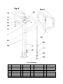
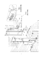
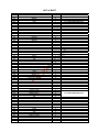
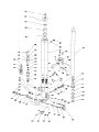
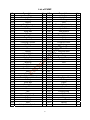
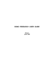
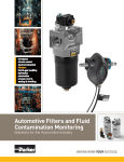
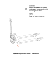
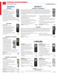
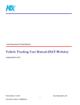
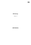
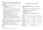
FH1025-SMS-001_EN
Operating Instructions
Parts List
Hand Stacker
1.0T/2.5M
Note: Owner and operator MUST read and understand this operating
instructions before use this hand stacker.
Date:March , 2012
Welcome to use our hand stacker. Your stacker is made of high quality steel and was designed to give a
durable, reliable and easy to use product. For your safety and correct operation, please carefully read
this instruction book and warnings on the stacker before using it.
NOTE: All of the information reported herein is based on data available at the moment of
printing. The factory reserves the right to modify its own products at any moment without notice
and incurring in any sanction. So, it is suggested to always verify possible updates.
1. STRUCTURAL DATA FORM
Capacity
Max. Fork Height
Min. Fork Height
Fork Length
Size of fork
Fork Width(outside)
Fork Width(inside)
Over Height
Over Width
TYPE I (Adjusted fork)
TYPE II (Fixed fork)
1000 kg
2500 mm
85 ± 2mm
900mm
1150 mm
150x60mm
160x60mm
330~740mm
550 mm
30~440mm
230 mm
1830mm
775mm
715mm
2. SAFETY GUIDANCE
2.1
2.2
Operator should read all warning signs and instructions here and on the stacker before using it.
Do not operate an hand stacker unless you are familiar with it and have been trained or
authorized to do so.
2.3 Do not operate an hand stacker unless you have checked its condition. Give special attention to
the wheels, the handle, the guide frame, the pilot wheel, the doorframe, etc.
2.4 Do not use on a slopping ground.
2.5 Do not take up any people on the forks.
2.6 The operator had better take on gloves for labor protecting.
2.7 When the goods have been transported or lifted, all people should be away form the forks for
600mm.
2.8 Do not load over maximum capacity.
2.9 The weight of goods should be distributed on the two forks, do not use only one fork. The center
of gravity of goods should be in the center of two forks.
2.10 People forbid to stand under the forks.
2.11 Do not move the hand stacker when the goods are lifted to the height more than 300mm.
2.12 At other special condition or place, the operator should be carefully to operate the hand stacker.
3. MAINTENANCE
3.1 Hydraulic oil
Please check the oil level every six months. The oil can be hydraulic oil: ISO VG32, its viscosity
should be 32cSt at 40oC, total volume is about 2.5lt.
3.2 Daily check and maintenance
It is necessary to check the hand stacker daily. Special attention should be paid to the wheels, the
axles, as thread, rags, etc., it may block the wheels, the fork and the mast should be checked, too. The
forks should be unloaded and lowered in the lowest position when the job is over.
3.3 Lubrication
Use motor oil or grease to lubricate all movable parts.
3.4 Remove the air
The air maybe enter the hydraulic pump during the transportation after the customer buys it. It will
cause the piston rod to fail to keep up the raised height. The air can be removed in the following way:
pull the control handle(D608) up and move handle(D610) up and down for several times.
1
4. TO ADJUST RELEASE DEVICE
On the draw-bar of this hand stacker, you can find the control handle (D608) which can be regulated in
three positions: LOWER = to lower the forks; NEUTRAL = to move the load, and
LIFT = to raise
the fork. These three positions have been pre-posited at the factory. If however they have been
changed, you can adjust according to following step:
4.1 If the forks elevate while pumping in the NEUTRAL position, turn the adjusting nut (D615) on the
adjusting bolt (D614) clockwise or turn the adjusting screw (234) clockwise until pumping action does
not raise the forks and the NEUTRAL position functions properly.
4.2 If the forks descend while pumping in the NEUTRAL position, turn the nut (D615) or the screw
(234) counter-clockwise until the forks do not lower.
4.3 If the forks do not descent when the control handle (D608) is in the LOWER position, turn the nut
(D615) or the screw (234) clockwise until raising the control handle (D608) lowers the forks. Then check
the NEUTRAL position according to item 4.1 and 4.2 to be sure the nut (D615) and the screw (234) is
in the proper position.
4.4 If the forks do not elevate while pumping in the LIFT position, turn the nut (D615) or the screw (234)
counter-clockwise until the forks elevate while pumping in the LIFT position. Then check the LOWER
and NEUTRAL position according to item 4.1, 4.2 and 4.3.
5. TROUBLES SHOOTING
No
Trouble
Clause
1 The forks cannot be - The hydraulic oil is not enough.
up the max. height.
- Without hydraulic oil.
- The oil has impurities.
2 The forks can not - The nut (D615) is too high or the
be lifted up.
screw (234) is too close, keep the
pumping valve open.
- Air come into the hydraulic oil.
- The piston rod(270) or pump body
(261) or the mast (5) is deformed
resulting from loading slanting to one
side or over-loading.
3 The forks can not - The fork was kept in the high
be descended.
position for long time with piston rod
bared to arise in rusting and jamming
of the rod.
- The adjusting nut (D615) or the
screw (234) is not in the correct
position.
- The rollers (42) are not lubricated.
- Sealing parts worn or damaged.
4 Leaks
- Some part cracked or worn into
small.
- The impurities in the oil cause the
release valve to be unable to close
tight.
5 The fork descends - Some parts of hydraulic system is
without the release cracked or bored.
valve worked.
- Air come into the oil.
- Sealing parts worn or damaged.
- The adjusting nut (D615) or the
screw(234) is not in the correct position.
Fixing Methods
- Pour in the oil.
- Fill in the oil.
- Change the oil.
- Adjust the nut (D615) or the
screw (234) .(see item 4.4)
- Banish the air.(see item 3.4)
- Replace it.
- Keeping the fork in the lowest
position if not using, and pay more
attention to lubricate the rod.
Adjust the nut (D615) or the
screw (234). (see item 4.3)
- Lubricate its.
- Replace with the new one.
- Replace with the new one.
- Replace with new oil.
- Inspect and replace the waste
parts.
- Banish the air. (See item 3.4)
- Replace with the new one.
- Adjusting the nut (D615) or the
screw (234). (See item 4.2)
NOTE: DO NOT ATTEMP TO REPAIR THIS STACKER UNLESS YOU ARE TRAINED AND
AUTHORIZED TO DO SO.
2
3
List of Handle
No.
Description Qty.
D601
Spring
1
D602 Blade Spring
1
D603
Roller
1
D604
Elastic Pin
1
D605
Elastic Pin
1
D606
Elastic Pin
1
D607
Elastic Pin
1
D608 Control Handle 1
D609
Pull Board
1
Remark
No.
D610B
D610A
D611
D612
D613
D614
D615
D616
4
Description
Handle
Handle
Screw
Chain
Pin
Adjusting Bolt
Adjusting Nut
Elastic Washer
Qty.
1
1
3
1
1
1
1
3
Remark
For Type A
For Type B
5
LIST of MAST
NO.
101
102
103
104
105Y
105G
106
107
108
109
110
111
112
113
114
115
116
117
119
120
121
122
123
124
125
126
127
128
129
130
131
132
133
134
135
136
137
138
139
140
141
142
143
144G
145Y
146Y
147Y
148Y
150
151
152
153
154
155
156
157
158
159
160
161
162
Description
Reticulation
Fixing Plate
Washer
Screw
Mast
Mast
Nut
Nut
Bolt
Bolt
Elastic Washer
Washer
Bearing
Bearing
Nut
Washer
Axle
Bearing
Nut
Wheel
Frame of Wheel
Screw
Frame of Wheel with Brake
Brake Plate
Spring
Bolt
Nut
Nut
Screw
Pedal
Elastic Pin
Cam
Locking Ring
Shaft
Roller
Washer
Shaft of Roller
Locking Ring for Axle
Bolt
Nut
Steel Ball
Locking Ring for Hole
Roller
Fixed Fork
Frame of Fork
Adjusting Fork
Retaining Ring
Long Axle
Nut
Pin
Bolt
Chain
Linking Plate
Screw
Locking Ring for Axle
Roller
Axle with Flange
Bolt
Screw
Roller for Chain
Inner Mast
Qty.
1
6
6
6
1
1
3
2
1
1
1
1
2
2
2
2
2
18
1
2
1
2
1
1
1
1
1
1
1
1
1
1
1
1
2
4
2
14
4
4
4
10
8
4
1
2
2
1
4
2
2
2
1
2
4
2
2
6
1
2
1
6
Remark
For TYPE I (Adjusted Fork)
For TYPE II (Fixed Fork)
For TYPE II (Fixed Fork)
For TYPE I (Adjusted Fork)
7
List of PUMP
NO.
201
202
203
204
205
206
207
208
209
210
211
212
213
214
215
216
217
218
219
220
221
222
223
224
225
226
227
228
229
230
231
232
233
234
235
236
237
238
239
240
241
Description
Dust Ring
Cover with Screw
O-Ring
Sleeve
Seal Washer
Pump Piston Rod
O-Ring
Steel Ball
O-Ring
Shaft
Dust Ring
Seal
Pumping Cylinder
O-Ring
Washer
Pin
Spring
Valve Spindle
Cap of Pin
Spring Cap
Spring
Bushing
Seal Washer
Bolt
Seal Washer
Bolt
Spring
Valve Spindle of Pump
Seat of Pump Valve
O-Ring
Steel Ball
Elastic Pin
Lever Plate
Screw
Nut
Spring
Release Valve Pin
O-Ring
O-Ring
Bolt
Safety Valve Spindle
Qty.
1
1
1
1
1
1
1
1
1
1
1
1
1
1
1
1
1
1
1
1
1
2
1
1
1
1
1
1
1
1
1
1
1
1
1
1
1
2
1
1
1
8
NO.
242
243
244
245
246
247
248
249
250
251
252
253
254
255
256
257
258
259
260
261
262
263
264
265
266
267
268
269
270
271
272
273
274
275
276
277
278
279
280
281
Description
Spring
Adjust Screw
O-Ring
Bolt
Pin to Adjust Velocity
Spring
Adjust Screw
Seal Washer
Bolt
Elastic Washer
Bolt
Shaft
Pressure Roller
Bushing
Elastic Pin
Elastic Pin
Axle with hole
Bracket
Bolt
Body of Pump
Seal Washer
Bolt
Qty.
1
1
1
1
1
1
1
1
1
2
2
1
1
1
1
1
1
1
3
1
1
1
Lifting Piston Rod
O-Ring
Piston
O-Ring
Seal
Washer
Locking Ring
Pedal
Bolt
Nut
Lever of Pedal
Spring
1
2
1
1
1
1
1
1
1
1
1
2