1
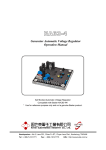
MPPT SOLAR CHARGE CONTROLLER
MPPT15—MPPT6O USER MANUAL
Thank you for purchasingour MPPT solar charge controller.
Please Read this manual Before Proceeding.
Our controller named as follow: (Please speci1. the itetu No before
you place order)
MPPT 15(60)
15: Maximum current (A), 15
=
15A(60A)
Warnlng:
Before connecting to the solar panel. please connect the controller to
Ihe batlery. do not use solar panel suppl power to the loads directly.
Notes:
Do not use lampltght to charne the solar panel (laniplight ta bo weak
bocharge)
DC power source to replace [lic solar panel will cause troubles to controlle
Choose ihe srutable re which diameter stiould not be bo smalI. please
refer to the parameter.
MPPT: MPPT tunction
1. SAFETY
4. INDICATE LIGHT AND BUTTON
Fuil consideration to the safety of persons and property bas
been giyen when designing the products. Howeyer the
incorrect connection may cause the system breakdown or
eyen safety accident. For your safety and benefits, the
following rules must be complied during the operation.
• When Red LED(CHARGE) ison, battery is chaaged up strongiy
When Red LED is lbckering. buttery is MPPT chaiged up in constant
• lnstallation ofthis product shall be under the guidance ofthe
professionals in this field.
• Preyent this controller from water, humidity and insects. to ayoid
short-circuit.
• Keep children aud ineapable persona away from the controllec
• Keep the controller away from elcetrical heater. heating machine
aud other high temperature eleetrical appliances ayoid the
controller suffering from insolation directly.
• Please cheek the rated yoltage of solar panel, batteiy, and loads
before connection, 12V rated yoltage is 12V, 24V rated yoltage is
24V, 48V rated yoltage is 48V
• Make sure conneetions between positiye aud negatiye poles of
Solar panels, Battery and Loads arc correet
• The diameter of connecting cable inust be matched with the
requirements of tbe current. Do not use thinner diameter cable,
the thinner diajneter. the larger resistance, this will cause higher
temperature aud output power decreaaing.
• The total rated current of solar panel and loads must be smaller
than [be rated current ofthe controller.
• Components of system naust be colTectly and tinnly coisnccted.
Preyent the terminals from oxidation and moldy. to ayoid
connection trouble.
yoltage when Red LED is olT: charge oLE
• When Green LED(LOAD) os on, boads are working when Green LED
(LOAD) is oli; bada stop working.
• Thrce Color-changing LED( BATTERY), When light is red, it indicates
bw yoltage, green indicate battei i hill charged,omnge indicate normal
status,
Color—changing LED working yoltage indicate area:
Color-elianglngLEfi
Orange LED
Green LED
• MPPT solar charge controller \IPPT 10-60: Compared with norinal
solar charge controller. this MPPT coutroller could inerease eliiciency
liv 10°o-30°.o.
• This controller can charge aud discharge ar Uie same time.
• This WPT controller lias perfeet SOC hmction. control charge
current. and supply power to [be loads.
Function:
• Always keep tiie battery on hill yoltage condition.
• Preyent the bartery froni oyer-charging.
• Pre%”ent [he battery frorn oyer-dischargiaig.
• Preyent the battery from reyerse chargmg to solar panels during nights.
• Rcyerse Polarity Protection for Battcrs”
• Reyersc Polarity Protection for Solar panela
• When Ihe battery yoltase is bw. [lic controller n iii automatically
cut olfthe bad trom luc system. Ifthc yoltage of battery is back to
normal aad tlie bad will restart working.
• Thunder protection
• Accordiiig to the battery yol[age grade. Ihe controller can
automatically set charge-otfyoltage. [be boad-otlyoltage. [lic bad
restoreyoltage.(The parameter is defauli under 25 condition.
bocked by the CPU procedure. cannot adjuat.)
• Tlie controller will autornaticaUy compensate the telnperature of
thc ehargmg yoltage accordmg to the chaages ofarnhient temperature
3. CONNECTION
As shown in the following diagram of connection, there are
6 terminais on the controller with elear sign.
SOLAR CONTROt.LR
O
ML
+
Solar paneis
+Hh +L
Battery
Loads
48V
10.5
11y-13,7V 21
21y—22y
42V-44y
-
13.7y
22y-27,4y 42
44V-54.XV
54.8y
27.4V
5. PARAMETERS
Sston
2. FEATURES
bO.5y--1Iy
Red LED
24V
12V
1P”l”15
MPP”ris
RatedVtage
tO..
15,
Iupstileos
„
Length0”lm
Ful chsrecut
MPPT3o
(
NtPt”T
(
MPPI68
12V 24V 48V
MeLtadturr
Clirtelei 1101
( MwF3o
20A
30A
(ss\
OsK
„..Osi\
Om
KSOsiV
KOOinV
K5Orny
5tuoV
„„
137V
LowyoItc
144V 274V „28 8V 54 8V
105V
J
60.4
-WA
24y-4JV 4Sy”80y
12V 2O\
Om\
K OsK
„i”Ois\
K50n”ty
K60mV
5nV
„..
576V ( dan salet as bal cendihoa)
11V 21 \„ 22V. 42V44y
łemera1ure
copisn
-3nsy
„t. / celi
Yoloadboss KlOniA „10rnA t20mA 2QniA t30mA K-łlJnt.4 K,45tnA
Errwiency
Muarnreura
950o_970o
2 5mm
95,9?%
9eo—97°o
9505_970,
2 Smm
4nim”
6mm”
95o97o 95%—970, 9%97%
tmm
lOnom”
l2nim
Ambient
lemperuture
6. TROUBLE SOLUTION
Phenomenon: Green LED oLE battery indicator LED ja red.
Reason: Low yolbage ofbattery
Solution:
A: Cut olfthe power. disconnect the bad. reconnect the bad after the
chargot become normal.
B: Battery charge problem: Iiicrease [be sobar panel power or change
the battery.
Phenomenon: Batter indicator LED is orange aud Load indicator LED
is green. bbc boads cannot work.
Reason: Oyer bad or short-circutt causes the controlber inner fuse cut ot
Solution: 10-20 minutes after eliminated the mabfunction, the fi.use will
automatically back to working.
____
nMPPTJmIJ
MPPT15—MPPT6O!)jĄ
*1JB
3,
ps
•
•
•
•
ItIJ\,
MPPT 15(60)
15:
15A(60A)
MPPT
4.
MPPT
IJ( CHARGE),
IEMPPT,
MPPT
•
•
*TŁ1
—iT (LOAD), 1d1.
0
TI1”Ę
JI1”;
• $—iI (EJ) (BArrEI),
IEI5F
•
• 7J( i5L .„
•
rf)IIui
•
OYĆ
XT
•
12V12V; 24V
0
jL24V; 48VB48V
•
3tt1
iJ\ĘJ,
•
IJ
10.5
-
+
48V
42V-44V
11V-13 7V 21 22V-27.4y 42
137V
27.4V
44y-54.8y
54.8V
5.#
•
•
P*
14,
2.
ł
MPPTI5
j MPPTI5 j MPPT3O
MPPTJO
j MPPT6O j MPPT6O
łtj1
i4
IOA
JE: MPPT
10%—30%
BMPPT
•
•
24V
21y-22y
0
TiJ\
iVL
• MPPT15-60
(f)
12V
10.5y-iły
$isw5
5
rd
iy
4aF
•
•
1jJf
•
•
• JiJ-_Ą
„
60A
-
K2\
-
<15Oiiy
25OmV 25Om
<25OmV <25OmV
K5(h
5(y
<SOm\,
<.9OmV
<.5OmV 5OmV
-
K5(ny
137y--144y/27.4y---28 8y!548y--57.6y
105y--11y/2y--22y/42y---44y
-3my”
I colt
„]OmA i]OmA i2OmA 2Onią 3OmA 4OmA 5i45mA
95%—97% 95%—97% 95%—97% 95%—97% 95%—97% 95%—97% 95%—97%
25mm
•
50A
K2,Om\
ł1IJfł
1ił”U7Ił
40A
30A
20A
12V—2Oy/24y4Oy4y—-8Oy
Jł#ŁJf
•
•
f
15A
-
2Smm
6mm
4mm
8mm
lOmrn
l2mm
-25t—sst
•
1J
BM (cPu, TJ)
25C
•
k5
r1 i
3. _1j
*: fl%L
1TMI
5U1EF
:
nJ
SOLAR CONTROLLER
A.
O
B.
...
]„
()
+
+
+
OPEM3t
0
1J () IE,
:
ł10-203,
Solar panela
Bauery
Loads
kI1”Ę