1
FAMILIARIZATION GAS TANKERS
1
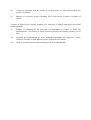
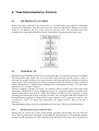
INTRODUCTION
This course is intended for officers and key ratings that have not previously served on board
liquefied gas tankers as part of the regular complement. It covers mandatory minimum training
requirements prescribed by Regulation V/1, paragraph 1.2 of the International Convention on
Standards of Training, Certification and Watchkeeping for Seafarers, STCW-95 and it includes
basic safety and pollution-prevention precautions and procedures, layouts of different types of
liquefied gas tankers, types of cargo, their hazards and their handling equipment, general
operational sequence and liquefied gas tanker terminology.
1.1 THE COURSE
The background for and the purpose of the course as being:
- The STCW-95 Convention contains mandatory minimum requirements for training and
qualification of masters, officers and ratings of liquefied gas tankers.
- This training is divided into two parts:
· Level 1: liquefied gas tanker familiarization – a basic safety-training course for officers and
ratings on board.· Level 2: advanced training in liquefied gas tanker operations for masters,
officers and others who are to have immediate responsibilities for cargo handling and cargo
equipment.
- This course covers the requirements for level 1 training required by Regulation V/1,
paragraph 1.2 of the International Convention on Standards of Training, Certification and
Watchkeeping for Seafarers, STCW-95
1.2 DEVELOPMENT OF LIQUEFIED GAS SHIPPING
Learning Objectives
Lists important stages in the transport of liquefied gas by ships, such as:
· gas shipping began in the late 1920s
· the earliest ships were designed to carry liquefied gas in pressure vessels at ambient
temperature
· the first cargoes on the market were butane and propane
· development of refrigeration techniques and meta s suitable for low temperature made it
possible to carry liquefied gas at temperatures lower than ambient
· defines terminology and explains abbreviations commonly used aboard gas tankers and on gas
terminals
In the late 1920th transportation of liquefied gases in bulk started. In the very beginning it was
transportation of propane and butane in fully pressurised tanks. Around 1959, semi-pressurized
ships entered the market and liquefied gas was now transported under lower pressure, which
was made possible by lowering the temperature. By 1963, fully refrigerated ships for LPG,
LNG and certain chemical gases wore in service, carrying cargo at atmospheric pressure.
Liquefied gas is divided into different groups based on boiling point, chemical bindings,
toxicity and flammability. The different groups of gases have led to different types of gas
carriers and cargo containment system for gas carriers.
The sea transport of liquefied gases in bulk is internationally regulated - with regard to safety
through standards established by the International Maritime Organization (IMO) and these
standards are set out in the IMO's Gas Carrier Codes, which cover design, construction and
other safety measures for ships carrying liquefied gases in bulk.
1.3 TERMINOLOGY
BOILING: This is the action, which takes place when a liquid changes its state from a liquid
into a gas or vapour. The heat required to bring this change of state about is called Latent Heat.
BOILING TEMPERATURE: This is the temperature at which a liquid boils. As the boiling
temperature rises with an increase in pressure (see saturated vapour pressure), the boiling
temperatures are usually given for atmospheric pressure. At this pressure, water boils at +
100oC. butane at - ½oC., ammonia at -33oC. and propane at -43oC.
CONDENSATION: This is evaporation in reverse. If a vapour becomes supersaturated,
condensation takes place and heat is surrendered. For example, in a seawater-cooled condenser,
a compressor has raised the pressure of the vapour to such an extent that at seawater
temperature, it is supersaturated. Condensation takes place, and the latent heat released heats up
the water passing through the condenser tubes; the heated seawater passing overboard into the
sea, to be replaced continuously by fresh cool water. The resulting condensate will be
somewhat warmer than the seawater coolant.
EVAPORATION: This is the process of converting a liquid into a vapour, and it requires latent
heat to do this. If a liquid (say liquid propane) in a closed container at 10oC. Has a saturated
vapour pressure of 5 atmospheres, and the vapour in the space above the liquid is allowed to
escape, the pressure in the container will fall. As soon as this happens, the vapour in the space
above the liquid will be undersaturated and evaporation will take place (or the liquid boil). Heat
will be used up in the boiling process and the temperature of the liquid will fall. The "boil off"
will largely replace the vapour which has been allowed to escape until such time as the pressure
in the container corresponds to the saturated vapour pressure of the liquid at the new lower
temperature. Continuous withdrawal of vapour means continuous evaporation, which in turn
means continuous loss of heat (cooling).
FILLING OF CARGO TANKS: The correct maximum volume of liquid to load in a cargo tank
is such a quantity that after allowance for the product to warm up and expand to a temperature
the saturated vapour pressure of which would lift the safety valves, 2 per cent. of the space
would remain. A tank so filled is described as Full. A tank filled above this level is described as
Overfull. A tank completely filled with liquid is described as one hundred per cent.
FLASHOVER: Firefighting on board ships differs from firefighting ashore in that allowance
has to be made for the fact that the metal with which a ship is constructed, conducts heat to a
far greater extent than normal shore building materials. The result is that a fire on board ship
tends to spread horizontally as well as vertically.
If the temperature of combustible material in a compartment adjacent to one where a fierce fire
is burning, is raised to above its ignition temperature (q.v.), that material will ignite
spontaneously (auto ignition), so spreading the fire from one compartment into another,
through a bulkhead, without a spark or flame being directly involved. Such a means of a fire
spreading is termed a flash-over.
GAS/VAPOUR: Gas is a substance which has the property of indefinite expansion. In the
context of this book, it is above its critical temperature and cannot be condensed into a liquid. If
the temperature of a gas is reduced to below its critical temperature, it then becomes a vapour,
and can be condensed into a liquid. Gases are frequently referred to as incondensibles.
Flammable or Explosive Mixture: Petroleum as a liquid does not burn. At ordinary
temperatures, it gives off vapour, which when mixed within certain proportions with air, will
burn. The lowest proportion of petroleum vapour in air mixture, which will burn, is termed
lower explosive limit (L.E.L.) and the strongest mixture that will burn is termed upper
explosive limit (U.E.L.). The flammable mixtures between the lower and upper explosive limits
are called the explosive range. A mixture of vapour in air weaker than the L.E.L. is described
as too lean or over-lean whilst a mixture of vapour in air stronger than the U.E.L. is described
as too rich or over-rich. Mixtures outside the explosive range will not burn, the words explosive
and flammable within this context being virtually synonymous.
Flash Point: This is the lowest temperature at which a flammable mixture of air and vapour will
burn when exposed to a naked flame.
Ignition Temperature: This is the temperature at which a flammable mixture of vapour and air
will ignite spontaneously (without being exposed to a naked flame). The operation of a diesel
engine depends upon this effect.
GAS LAWS
Avogadro's Hypothesis: Equal volumes of different gases at the same pressure and temperature
contain the same number of molecules.
Boyle's Law: The volume of a given mass of gas varies inversely with the pressure provided
that the temperature remains constant:
P=
Charles's Law: The volume of a given mass of gas varies directly with the absolute temperature
provided the pressure remains constant:
Volume =
or density =
Clerk Maxwell's Kinetic Theory: A gas may be imagined as a vast number of molecules
moving in all directions at irregular velocities, colliding with one another and with the walls of
the containing vessel. The path of a molecule is zigzag in three dimensions and the mean free
path is defined as the average length between collisions, the denser the gas, the shorter will be
the mean free path.
On the assumption that the molecules are microscopic spheres, it can be shown that the
pressure and absolute temperature of a gas are proportional to the mean kinetic energy of
translation of the molecules bombarding the walls of the vessel containing the gas. Thus, at the
same temperature the average kinetic energy of translation of the molecules of any gas are the
same whatever its mass-a "large" molecule having low velocity and a "light" molecule having
high velocity.
This theory correlates Avogadro's Hypothesis, Boyle's Law, Charles's Law and Gay Lussac's
Law.
Dalton's Law of Partial Pressures: The pressure of a mixture of gases is the sum of the
pressures each would exert if it alone were to occupy the containing vessel.
Gay Lussac's Law: The density of a gas at standard pressure and temperature is proportional to
its molecular weight. This is a corollary of Avogadro's Hypothesis.
Joule's Law: When a perfect gas expands without doing external work and without taking in or
giving out heat and therefore without changing its stock of internal energy, its temperature does
not change.
HEAT
Latent Heat: This is the heat used up in changing the state of a substance without changing its
temperature. In the case of changing the state of a substance from a solid into a liquid
(melting), it is called the latent heat of fusion, and in the case of heat changing the state of a
liquid into a gas or vapour (boiling), it is called the latent heat of vaporisation. It takes 80
calories to change 1 gramme of ice into water and about 539 calories to change 1 gramme of
water into steam at standard atmospheric pressure. The value of latent heat of vaporisation
varies with temperature and pressure (see critical temperature).
Sensible Heat: This is the heat used in raising the temperature of a substance without changing
its state. 1 calorie is used to raise the temperature of 1 gramme of water 1oC.
HEEL: This is the small quantity of liquid remaining after discharge which it is impossible to
pump out, but which is used to assist in keeping the cargo tank cold during the ballast
(unloaded) passage, and is usually carried over to the next loading. When it is know that the
vessel will be changing grades or gas freeing, every effort should be made to reduce this heel to
the absolute minimum.
LIQUID CARRY OVER: This occurs when vapour moves swiftly over the surface of a liquid
and droplets of liquid become entrained with the vapour and are carried over with it.
It is the entrained droplets of lubricating oil that are recovered in the lubricating oil separator
trap of the compressor, and entrained liquid droplets which cause wet suction on a compressor.
MOLE: This is the quantity of gas the weight of which is equal to its molecular weight in
pounds or grammes. Thus a mole of hydrogen would be 2, a mole of oxygen 32 etc. This is
fairly closely related to Avogadro's Hypothesis, a mole having the same volume for all products
at the same pressure and temperature.
PRESSURE
Absolute Pressure: This is the pressure above a vacuum. Thus a pressure of 7 p.s.i. absolute, is
really a suction pressure of 7.7 p.s.i. at atmospheric pressure (atmospheric pressure equals 14.7
p.s.i.).
Gauge Pressure: This is the pressure above one atmosphere and is the usual method of
measuring pressures and vacuums. Absolute pressure is therefore equal to gauge pressure plus
one atmosphere.
Atmospheric Pressure: This is the pressure exerted at sea level. This pressure varies from place
to place and from time to time. The standard atmospheric pressure is 1012.5 millibars,
corresponding to 29.90 inches or 760 millimetres of mercury.
SPAN GAS: This is a laboratory-measured mixture of gases used for the purpose of calibrating
gas detectors. In gas tankers, the mixture is usually 30 per cent. L.E.L. of the product mixed
with pure nitrogen.
STRATIFICATION: This is the layering effect of two gases or vapours with dissimilar
densities, the lighter vapour floating above the heavier.
TEMPERATURE
Absolute Temperature: As a result of studying Charles's Law, it seemed that the volume of a
gas would reduce to nothing at about -273oC. (or absolute zero). (Physicists have never been
able to reach this temperature.) It therefore follows that absolute temperature equals
temperature + 273oC.
Adiabatic Changes in Temperature: When a gas (or vapour) is compressed, its temperature
rises. When it expands, its temperature falls. This is the adiabatic process and compression
ignition (diesel) engines rely upon this property for their operation.
Critical Temperature: This is the temperature above which it is not possible to liquefy a gas.
Saturated vapour pressure rises with an increase in temperature. At the same time, the density
of a liquid falls with an increase in its temperature. Therefore, there must come a time when so
many atmospheres of pressure are required to liquefy the vapour that the density of the
compressed vapour and the liquid are the same. When this state is achieved, there is virtually
no difference between the liquid and vapour phases and they freely change into each other. The
value of latent heat is reduced to zero and with any increase in temperature, no amount of
increasing the pressure will bring about liquefaction, and the vapour is then described as a gas.
Associated with the critical temperature is the critical pressure.
VAPORISATION: This is the action of converting a liquid into a vapour.
Batch Vaporisation: This is the method of evaporation whereby vapour is withdrawn from the
top of a tank, causing the liquid in the tank to boil, with a consequent drop in temperature. With
a mixture of products such as butane and propane, the more volatile element tends to evaporate
first, so that the proportions comprising the mixture will change and after a time one is left with
almost pure butane. This process of altering a mixture in a tank due to the volatile constituent
evaporating first is called "weathering". However, batch vaporisation is the simplest method
and because, in L.P.G. tankers, the vapour which has been withdrawn is condensed into a liquid
and returned to the tank, there is no tendency to alter the constituents of the mixture, so this is
used as a method of refrigeration.
Flash Vaporisation: This is the method whereby liquid is withdrawn from the bottom of the
tank and evaporated in a vaporising unit. In this method, the constituents of a mixture remain
fairly constant, as does the temperature of the product in the tank.
VAPOUR: This is the term used for a "gas" below its critical temperature and therefore capable
of being liquefied.
Saturated Vapour Pressure (S.V.P.) All liquids tend to evaporate under normal conditions, but
if kept in a closed container, evaporation will only take place until the atmosphere in the
container becomes saturated. In the case of water, the following experiment can be carried out.
Into the top of a barometer some water is introduced. Due to the evaporation of the water that
has been introduced, the level of the mercury will fall. If sufficient water is introduced, the
level will virtually stop falling because the space above the mercury will be saturated with
water vapour, and a little water will show on top of the mercury. The fall in the mercury level
converted into pressure would indicate the absolute S.V.P. at that temperature. By rising the
temperature, more water will evaporate and the level of the mercury fall further. The new level,
converted into pressure, will indicate the new S.V.P. at the new temperature. At 100oC, the
level of the barometer will register zero. The absolute vapour pressure of water at 100oC. is
therefore one atmosphere (1.0125 bar). It therefore follows that under atmospheric conditions, a
liquid will, apart from minor evaporation, keep its state until with the addition of heat, and its
absolute S.V.P. reaches one atmosphere. From then on, all the extra heat will be used to assist
evaporation and the temperature will not rise. In other words, the liquid boils. If the boiling
action takes place in a closed container, e.g., a boiler, as the temperature rises, so the pressure
increases. That is, the boiling temperature of the water rises as the pressure increases. The
pressure in the boiler is an indication of the water temperature and vice versa.
If a thermometer and pressure gauge were fitted to a container holding, say, propane, the
temperature and pressure would be directly related to each other, the pressure rising as the
temperature rose and vice versa.
A sudden release of pressure would result in continuous evaporation, this using up latent heat
so cooling the liquid until the temperature of the liquid reached that appropriate to the S.V.P. of
the product at the new pressure. This means that if warm propane escaped onto the deck, it
would immediately evaporate and refrigerate itself down to approximately –43oC.
Supersaturated Vapour: If the vapour pressure in a container is rapidly increased, condensation
will take place, but until the process of condensation has been completed, the vapour will be
supersaturated.
Undersaturated Vapour: This is super-saturation in reverse.
Superheated Vapour: In the absence of liquid to continue the evaporating process and so keep
the vapour saturated, the vapour temperature can be raised to well above the temperature
corresponding to that at which the vapour would be saturated at the pressure concerned. Any
superheated vapour would have no tendency to condense. This property is used particularly
with steam. The saturated steam coming from the boilers is heated further in the superheater to
prevent condensation taking place in the engine.
VAPOUR RETURN LINE: This is a balancing pipeline between the ship when loading (or
discharging) and the shore tank, so that the vapour trapped in the space above the incoming
liquid, and therefore being compressed, is returned to the shore tank from which the product is
being discharged.
WET SUCTION: This occurs when liquid droplets are carried over into the compressor
suction, and get sucked into the compressor. It can only take place if the vapour at the
compressor suction is at or near saturation.
On the compression stroke, the adiabatic increase in temperature is used up evaporating the
liquid droplets which have been sucked into the cylinder, resulting in a dramatic drop in the
discharge temperature. The temperature of the cylinder head falls and in extreme cases can
become covered with ice.
Wet suction frequently causes damage to the compressor suction and discharge valves, and in
extreme cases, where too much unevaporated liquid collects in the cylinder, can cause the
cylinder head to be shattered.
ZERO GAS: This is pure nitrogen used to calibrate the zero reading of gas detectors.
2
PROPERTIES AND HAZARDS OF LIQUEFIED GAS
2.1
TYPES OF GAS CARRIERS
IMO divides liquefied gases into the following groups:
•
•
•
•
•
•
LPG - Liquefied Petroleum Gas
LNG - Liquefied Natural Gas
LEG - Liquefied Ethylene Gas
NH3 - Ammonia
Cl2 - Chlorine
Chemical gases
The IMO gas carrier code define liquefied gases as gases with vapour pressure higher than 2,8
bar with temperature of 37,8oC.
IMO gas code chapter 19 defines which products that are liquefied gases and have to be
transported with gas carriers. Some products have vapour pressure less than 2,8 bar at 37,8oC,
but are defined as liquefied gases and have to be transported according to chapter 19 in IMO
gas code. Propylene oxide and ethylene oxides are defined as liquefied gases. Ethylene oxide
has a vapour pressure of 2,7 bar at 37,8oC. To control temperature on ethylene oxide we must
utilise indirect cargo cooling plants.
Products not calculated as condensed gas, but still must be transported on gas carriers, are
specified in IMO’s gas code and IMO’s chemical code. The reason for transportation of noncondensed gases on gas carriers is that the products must have temperature control during
transport because reactions from too high temperature can occur.
Condensed gases are transported on gas carriers either by atmospheric pressure (fully cooled)
less than 0,7 bars, intermediate pressure (temperature controlled) 0,5 bars to 11 bars, or by full
pressure (surrounding temperature) larger than 11 bars. It is the strength and construction of
the cargo tank that is conclusive to what over pressure the gas can be transported.
2.1.1
LPG
LPG - Liquefied Petroleum Gas is a definition of gases produced by wet gas or raw oil. The
LPG gases are taken out of the raw oil during refining, or from natural gas separation. LPG
gases are defined as propane, butane and a mixture of these. Large atmospheric pressure gas
carriers carry most of the LPG transported at sea. However, some LPG is transported with
intermediate pressure gas carriers. Fully pressurised gas carriers mainly handle coastal trade.
LPG can be cooled with water, and most LPG carriers have direct cargo cooling plants that
condenses the gas against water.
The sea transport of LPG is mainly from The Persian Gulf to Japan and Korea. It is also from
the north- west Europe to USA, and from the western Mediterranean to USA and Northwest
Europe.
LPG is utilised for energy purposes and in the petro-chemical industry
2.1.2
LNG
LNG - Liquefied Natural Gas is a gas that is naturally in the earth. Mainly LNG contains
Methane, but also contains Ethane, Propane, and Butane etc. About 95% of all LNG are
transported in pipelines from the gas fields to shore, for example, gas pipes from the oil fields
in the North Sea and down to Italy and Spain. Gas carriers transport the remaining 5%. When
LNG is transported on gas carriers, the ROB and boil off from the cargo is utilised as fuel for
propulsion of the vessel. Cargo cooling plants for large LNG carriers are very large and
expensive, and they will use a lot of energy. Small LNG carriers have cargo-cooling plants, and
can also be utilised for LPG transportation.
The sea transport of LNG is from the Persian Gulf and Indonesia to Japan, Korea and from the
Mediterranean to Northwest Europe and the East Coast of USA and from Alaska to the Far
East.
LNG is used for energy purposes and in the petro-chemical industry.
2.1.3
NGL
NGL - Natural Gas Liquid or wet gas is dissolved gas that exists in raw oil. The gas separates
by refining raw oil. The composition of wet gas varies from oil field to oil filed. The wet gas
consists of Ethane, LPG, Pentane and heavier fractions of hydrocarbons or a mixture of these.
Atmospheric pressure gas carriers and semi-pressurised gas carriers carry the most of the wet
gas.
Ethane can only be transported by semi-pressurised gas carriers, which have direct cascade
cooling plants and are allowed to carry cargo down to –104oC. This is because Ethane has a
boiling point at atmospheric pressure of –89oC. This will create too high condense pressure if
using water as cooling medium. The cargo is condensed against Freon R22 or another cooling
medium with boiling point at atmospheric pressure lower than –20oC.
Wet gas is transported from the Persian Gulf to the East, Europe to USA and some within
Europe. There is also some transport of wet gas in the Caribbean to South America.
NGL is utilised for energy purposes and in the petro-chemical industry.
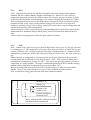
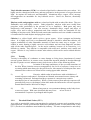
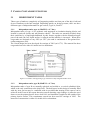
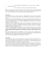
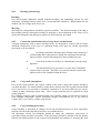
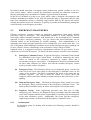
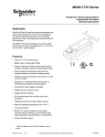
Methane CH4
Ethan C2H6
LNG
NGL
LPG
Propane C3H8
Butane C4H10
Pentane and heavier
fractions of HC
Water, carbon dioxide, nitrogen and other
non-hydrocarbon containment
2.1.4
COMPOSITION OF NATURAL GAS
2.1.5
LEG
LEG - Liquefied Ethylene Gas. This gas is not a natural product, but is produced by cracked
wet gas, such as, Ethane, Propane, and Butane or from Naphtha. Ethylene has a boiling point at
atmospheric pressure of -103,8oC, and therefore has been transported in gas carriers equipped
with cargo compartment that can bear such a low temperature. Cascade plants are used to
condense Ethylene. As critical temperature of Ethylene is 9,7oC one cannot utilise water to
condense Ethylene. The definition of Ethylene tankers is LPG/LEG carrier.
Ethylene is very flammable and has a flammable limit from 2,5% to 34% by volume mixed
with air. There are stringent demands regarding the oxygen content in Ethylene. The volume of
ethylene must be less than 2% in the gas mixture to keep the mixture below the LEL “lower
explosion limit”. Normally, there are demands for less than 0,2% oxygen in the gas mixture in
order to prevent pollution of the cargo.
Ethylene is utilised as raw material for plastic and synthetic fibres.
Ethylene is transported from the Persian Gulf to the East, the Mediterranean to the East and
Europe, the Caribbean to South America. There is also transport of Ethylene between the
countries Malaysia, Indonesia and Korea
2.1.6
AMMONIA NH3
The next gas we will focus on is Ammonia, which is produced by combustion of hydrogen and
nitrogen under large pressure. Ammonia is a poisonous and irritating gas, it has TLV of 25 ppm
and the odour threshold is on 20 ppm. It responds to water and there are special rules for
vessels that transport Ammonia. We can locate the rules in the IMO Gas Code, chapters 14, 17
and 19.
When ammonia gas is mixed with water, a decreased pressure is formed by 1 volume part
water absorbing 200 volume parts ammonia vapour. A decreased tank pressure will occur if
there is water in the tank when commence loading ammonia and the tank hatch is closed. With
an open hatch, we can replace the volume, originally taken up by the ammonia gas, with air.
One must not mix ammonia with alloys: copper, aluminium, zinc, nor galvanised surfaces. Inert
gas that contains carbon dioxide must not be used to purge ammonia, as these results in a
carbamate formation with the ammonia. Ammonium carbamate is a powder and can blockage
lines, valves and other equipment.
The boiling point for ammonia at atmospheric pressure is –33oC, and must be transported at a
temperature colder than –20oC. One can cool ammonia with all types of cargo cooling plants.
Ammonia is transported with atmospheric pressure gas carriers or semi-pressurised gas carriers.
Gas carriers carrying Ammonia must be constructed and certified in accordance with IMO’s
IGC code for transportation of liquefied gases. The definition for ammonia tanker is LPG/NH,
carrier.
Ammonia is utilised as raw material for the fertiliser industry, plastic, explosives, colours and
detergents.
There is a lot of transportation from the Black Sea to USA, from USA to South Africa and from
Venezuela to Chile.
2.1.7
CHLORINE CI2
Chlorine is a very toxic gas that can be produced by the dissolution of sodium chloride in
electrolysis. Because of the toxicity of Chlorine it is therefore transported in small quantities,
and must not be transported in a larger quantity than 1200m3. The gas carrier carrying chlorine
must be type 1G with independent type C tanks. That means the cargo tank must, at the least,
lie B/5 “Breadth/5” up to 11,5 meter from the ships side. To transport Chlorine, the
requirements of IMO IGC code, chapters 14, 17 and 19 must be fulfilled. Cooling of Chlorine
requires indirect cargo cooling plants.
The difference of Chlorine and other gases transported is that Chlorine is not flammable.
Chlorine is utilised in producing chemicals and as bleaching agent in the cellulose industry.
2.1.8
CHEMICAL GASES
The chemical gases mentioned here is the gases produced chemically and are defined in IMO’s
rules as condensed gases. Because of the gases’ boiling point at atmospheric pressure and
special requirements for temperature control, these gases must be carried on gas carriers as
specified by the IMO gas code. Condensed gases are liquids with a vapour pressure above 2,8
bars at 37,8oC. Chemical gases that are mostly transported are Ethylene, Propylene, butadiene
and VCM. Chemical gases that have to be transported by gas carriers are those mentioned in
chapter 19 in IMO IGC code. There are, at all times, stringent demands for low oxygen content
in the cargo tank atmosphere, often below 0,2% by volume. This involves that we have to use
nitrogen to purge out air from the cargo compartment before loading those products.
In addition, even though the vapour pressure does not exceed 2,8 bars at 37,8oC such as,
ethylene oxide and propylene oxide or a mixture of these, they are still in the IMO gas code as
condensed gases. Gas carriers that are allowed to transport ethylene oxide or propylene oxide
must be specially certified for this. Ethylene oxide and propylene oxide have a boiling point at
atmospheric pressure of respectively 11oC and 34oC and are therefore difficult to transport on
tankers without indirect cargo cooling plants. Ethylene oxide and propylene oxide cannot be
exposed to high temperature and can therefore not be compressed in a direct cargo cooling
plant. Ethylene oxide must be transported on gas tanker type 1G.
Chemical gases like propylene, butadiene and VCM are transported with medium-sized
atmospheric pressure tankers from 12000 m3 to 56000 m3. Semi-pressurised gas carriers are
also used in chemical gas trade and then in smaller quantity as from 2500 m3 to 15000 m3.
Chemical gases are transported all over the world, and especially to the Far East where there is
a large growth in the petro-chemical industry. Chemical gases are mainly utilised in the petrochemical industry and rubber production.
2.2
CARGO PROPERTIES
2.2.1
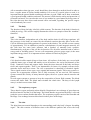
States of matter
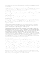
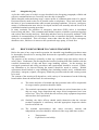
Most substances can exist in either the solid, liquid or vapour state. In changing from solid to
liquid (fusion) or from liquid to vapour (vaporisation), heat must be given to the substance.
Similarly in changing from vapour to liquid (condensation) or from liquid to solid
(solidification), the substance must give up heat. The heat given to or given up by the
substance in changing state is called latent heat. For a given mass of the substance, the latent
heats of fusion and solidification are the same. Similarly, latent heats of vaporisation and of
condensation are the same, although different from the latent heat of fusion or solidification.
Fusion or solidification occurs at a specific temperature for the substance and this temperature
is virtually independent of the pressure. Vaporisation or condensation of a pure substance,
however, occurs at a temperature which varies widely dependent upon the pressure exerted on
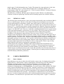
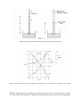
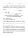
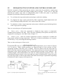
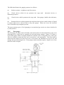
the substance. The latent heat of vaporisation also varies with pressure. Figure 2.1 illustrates
these temperature/heat relationships as a substance is heated or cooled through its three states;
the temperatures of fusion or solidification (A) and of vaporisation or condensation (B) are all
well defined. For liquefied cases, we are not concerned with the solid state since this can only
occur at temperatures well below those at which the liquefied gas is carried. Temperatures,
pressures and latent heats of vaporisation, however, are of fundamental importance. This data
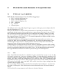
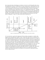
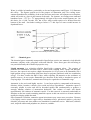
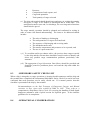
may be presented in graphical form such as Figure 2.2 which gives curves for vapour pressure,
liquid density, saturated vapour density and latent heat of vaporisation against temperature for
methane. Similar graphical presentation of these properties are available for all the principal
liquefied gases carried by sea and some of these presentations are reproduced in the Data
Sheets of Appendix 1 of the ICS Tanker Safety Guide (Liquefied Gas).
Figure 2.1 Temperature/heat energy relationship for the various states of matter
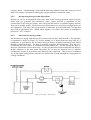
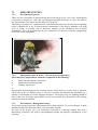
It is convenient here, against the background of the preceding, paragraphs, to consider what
happens when a liquefied gas is spilled. Firstly, consider the escape from its containment of a
fully refrigerated liquid. The liquid is already at or near atmospheric pressure but, on escape, it
is inevitably brought immediately into contact with objects such as structures, the ground or the
sea, which are at ambient temperature. The temperature difference between the cold liquid and
the objects it contacts provides an immediate transfer of latent heat to the liquid, resulting in
rapid evolution of vapour. The abstraction of heat from contacted solid objects cools them,
reducing the temperature difference and stabilising the rate of evaporation to a lower level than
initially until the liquid is completely evaporated. In the case of spillage on to water, the
convection in the upper layers of the water may largely maintain the initial temperature
difference and evaporation may continue at the higher initial rate. Spillage from a pressurised
container is initially different in that the liquid on escape is at a temperature not greatly
different from ambient temperature but the liquid is released from its containment pressure
down to ambient pressure.
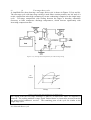
Figure 2.2 Vapour pressure (P), liquid density (у’), saturated vapour density (у’’)
(r) for methane.
and heat of vaporisation
Extremely rapid vaporisation ensues, the necessary latent heat being taken primarily from the
liquid itself which rapidly cools to its temperature of vaporisation at atmospheric pressure.
This is called flash evaporation and, depending upon the change in pressure as the liquid
escapes from its containment, a large proportion of the liquid may flash off in this way. The
considerable volume of vapour produced within the escaping liquid causes the liquid to
fragment into small droplets. Depending upon the change in pressure as the liquid escapes,
these droplets will be ejected with a considerable velocity. These droplets take heat from the
surrounding air and condense the water vapour in the air to form a white visible cloud and
vaporise to gas in this process. Thereafter any liquid which remains will evaporate in the same
way as for spilled fully refrigerated liquid until the spillage is wholly vaporised. Apart from the
hazards introduced by the generation of vapour which will become flammable as it is diluted
with the surrounding air, the rapid cooling imposed upon contacted objects will cause cold
burns on human tissue and may convert metallic structure to a brittle state.
Saturated vapour pressure
2.2.2
Vapour in the space above a liquid is not static since liquid molecules near the surface are
constantly leaving to enter the vapour phase and vapour molecules are returning to the liquid
phase. The space is said to be unsaturated with vapour at a particular temperature if the space
can accept more vapour from the liquid at that temperature. A saturated vapour at any
temperature is a vapour in equilibrium with its liquid at that temperature. In that condition the
space cannot accept any further vapour from the liquid, although a continuous exchange of
molecule, between vapour and liquid takes place.
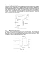
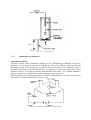
The pressure exerted by a saturated vapour at a particular temperature is called the saturated
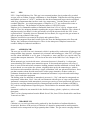
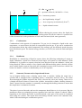
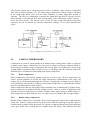
vapour pressure of that substance at that temperature. Various methods exist for measurement
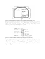
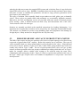
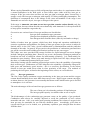
of saturated vapour pressures and one is illustrated in Figure 2.3. This apparatus consists of a
barometer tube (C) which is filled with mercury, inverted and immersed in a mercury reservoir
(A). The space above the mercury is a vacuum (B) though not perfect because of the presence
of mercury vapour in that space. The height of mercury (X) is a measure of atmospheric
pressure. A small amount of the liquid under test is introduced into the mercury barometer and
rises to the vacuum space where it immediately vaporises and exerts a vapour pressure. This
vapour pressure pushes the mercury down in the barometer tube to a new level (Y). The
saturated vapour pressure exerted by a test liquid is the difference between the heights of the
mercury column X and Y, usually expressed in mm of mercury.
If the mercury column containing the small amount of liquid under test is now suitably heated,
then the mercury level will fall indicating that the saturated vapour pressure has increased with
increasing temperature. It is possible by this means to determine the saturated vapour pressure
for the liquid under test at various temperatures.
Whereas evaporation is a surface phenomenon where the faster moving molecules escape from
the surface of the liquid, boiling takes place in the body of the liquid when the vapour pressure
is equal to the pressure in the liquid. By varying the pressure above the liquid it is possible to
boil the liquid at different temperatures. Decreasing the pressure above the liquid lowers the
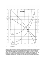
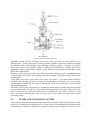
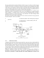
boiling point and increasing the pressure raises the boiling point. The curve marked P in Figure
2.4 illustrates the variation in saturated vapour pressure with temperature for propane. It will
be noticed that an increase in the temperature of the liquid causes a non-linear increase in the
saturated vapour pressure. Also shown on Figure 2.4 are the variations of propane liquid
densities and saturated vapour densities with temperature.
Figure 2.3 Barometer methods for measuring saturated vapour pressure (SVP)
Figure 2.4 Saturated vapour pressure (P), density of saturated vapour ( V ") and density of liquid ( P') for propane
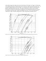
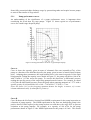
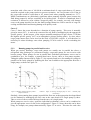
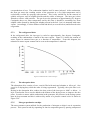
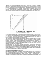
Different liquefied gases exert different vapour pressures as can be seen from Figures 2.5 and
2.6. The vertical axis in these two figures gives the saturated vapour pressure on a logarithmic
scale which changes the shape of the curves from that of P in Figure 2.4. Figure 2.5 shows that
for the hydrocarbon gases, smaller molecules exert greater vapour pressures than large ones. In
general the chemical gases shown in Figure 2.6 exert much lower saturated vapour pressures
than the small hydrocarbon molecules. The point of intersection of these curves with the
horizontal axis indicates the atmospheric boiling point of the liquid (the temperature at which
the saturated vapour pressure is equal to atmospheric pressure). This is the temperature at
which these cargoes would be transported in a fully refrigerated containment system.
Figure 2.5 Pressure/temperature relationships for saturated and unsaturated liquefied hydrocarbon gases
Figure 2.6 Pressure/temperature relationships for liquefied chemical gases
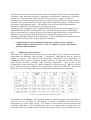
Whereas the bar is now the most frequently used unit in the gas industry for the measurement
of pressure, other units such as kgf/cm2, atmospheres or millimetres of mercury are frequently
encountered. The conversion factors for these units of pressure are given in Table 2.6.
All gauges used for the measurement of pressure measure pressure difference. Gauge pressure
is therefore the pressure difference between the pressure to which the gauge is connected and
the pressure surrounding the gauge. The absolute value of the pressure being measured is
obtained by adding the external pressure to the gauge pressure.
Vapour pressures, though they may be often determined by means of a pressure gauge, are a
fundamental characteristic of the liquid and are essentially absolute pressures. Tank design
pressures and relief valve settings, however, like pressure gauge indications, are physically the
differences between internal and external pressure and thus are gauge pressures. For
consistency throughout this book all such pressures are given in bars but to avoid confusion the
unit is denoted as "barg" where a gauge pressure is intended.
•
A liquefied gas has been defined in terms of its vapour pressure as being a
substance whose vapour pressure at 37.8o C is equal to or greater than 2.8 bar
absolute (IMO definition).
2.2.3
Liquid and vapour densities
The density of a liquid is defined as the mass per unit volume and is commonly measured in
kilogrammes per decimetre cubed (kg/dm3). Alternatively, liquid density may be quoted in
kg/litre or in kg/m3. The variation with temperature of the density of a liquefied gas in
equilibrium with its vapour is shown for propane in curve y' of Figure 2.4. As can be seen, the
liquid density decreases markedly with increasing temperature. This is due to the
comparatively large coefficient of volume expansion of liquefied gases. All the liquefied
gases, with the exception of chlorine, have liquid relative densities less than one. This means
that in the event of a spillage onto water these liquids would float prior to evaporation.
Table 2.7 Conversion factors for units of pressure
The variation of the density of the saturated vapour of liquefied propane with temperature is
given by curve y" of Figure 2.4. The density of vapour is commonly quoted in units of
kilogrammes per cubic metre (kg/m'). The density of the saturated vapour increases with
increasing temperature. This is because the vapour is in contact with its liquid and as the
temperature rises more liquid transfers into the vapour phase in order to provide the increase in
vapour pressure. This results in a considerable increase in mass per unit volume of the vapour
space. All the liquefied gases produce vapours which have a relative vapour density greater
than one with the exceptions of methane (at temperatures greater than –100oC). Vapours
released to the atmosphere and which are denser than air tend to seek lower ground and do not
disperse readily.
Flammability and explosion
2.2.4
Combustion is a chemical reaction, initiated by a source of ignition, in which a flammable
vapour combines with oxygen in suitable proportions to produce carbon dioxide, water vapour
and heat. Under ideal conditions the reaction for propane can be written as follows:
C3 H8
propane
+
502
Combustion
3CO2
+
4H2O
oxygen Ζ
carbon
water
dioxide
vapour
+
Heat
Under certain circumstances when, for example, the oxygen supply to the source of fuel is
restricted, carbon monoxide or carbon can also be produced.
The three requirements for combustion to take place are fuel, oxygen and ignition. The
proportions of flammable vapour to oxygen or to air must be within the flammable limits.
The gases produced by combustion are heated by the combustion reaction. In open, unconfined
spaces the consequent expansion of these gases is unrestricted and the combustion reaction may
proceed smoothly without undue overpressures developing. If the free expansion of the hot
gases is restricted in any way, pressures will rise and the speed of flame travel will increase,
depending upon the degree of confinement encountered. Increased flame speed in turn gives
rise to more rapid increase in pressure with the result that damaging overpressures may be
produced and, even in the open, if the confinement resulting from surrounding pipework, plant
and buildings is sufficient, the combustion can take on the nature of an explosion. In severely
confined conditions, as within a building or ship's tank where the expanding gases cannot be
adequately relieved, the internal pressure and its rate of increase may be such as to disrupt the
containment. Here, the resultant explosion is not so much directly due to high combustion rates
and flame speed as to the violent expulsion of the contained high pressure upon containment
rupture.
The boiling liquid expanding vapour explosion (BLEVE) is a phenomenon associated with the
sudden and catastrophic failure of the pressurised containment of flammable liquids in the
presence of a surrounding fire. Such incidents have occurred with damaged rail tank car or
road tank vehicle pressure vessels subject to intense heat from surrounding fire. This heat has
increased the internal pressure and, particularly at that part of the vessel not wetted by liquid
product, the vessel's structure is weakened to the point of failure. The sudden release of the
vessel's contents to atmosphere and the immediate ignition of the resultant rapidly expanding
vapour cloud have produced destructive overpressures and heat radiation. There have been no
instances of this kind, nor are they likely to occur, with the pressure cargo tanks on liquefied
gas tankers where, by requirement, pressure relief valves are sized to cope with surrounding
fire, tanks are provided with water sprays and general design greatly minimises the possibilities
of a surrounding fire occurring.
The term flammable range gives a measure of the proportions of flammable vapour to air
necessary for combustion to be possible. The flammable range is the range between the
minimum and maximum concentrations of vapour (per cent by volume) in air, which form a
flammable mixture. These terms are usually abbreviated to LFL (lower flammable limit) and
UFL (upper flammable limit). This concept is illustrated for propane in Figure 2.9.
All the liquefied gases, with the exception of chlorine, are flammable but the values of the
flammable range are variable and depend on the particular vapour. These are listed in Table
2.9. The flammable range of a particular vapour is broadened in the presence of oxygen in
excess of that normally in air; the lower flammable limit is not much affected whereas the
upper flammable limit is considerably raised. All flammable vapours exhibit this property and
as a result oxygen should not normally be introduced into an atmosphere where flammable
vapours exist. The oxygen cylinders associated with oxyacetylene burners and oxygen
resuscitators should only he introduced into hazardous areas under strictly controlled
conditions.
The flash point of a liquid is the lowest temperature at which that liquid will evolve sufficient
vapour to form a flammable mixture with air. High vapour pressure liquids such as liquefied
gases have extremely low flash points, as seen from Table 2.8. However, although liquefied
gases are never carried at temperatures below their flash point, the vapour spaces above such
cargoes are non-flammable since they are virtually 100 per cent rich with cargo vapour and are
thus far above the upper flammable limit.
Figure 2.8 Flammable range for propane
Table 2.9 Ignition properties for liquefied gases
Table 2.20 Flammability range in air/oxygen for various liquefied gases
The auto-ignition temperature of a substance is the temperature to which its vapour in air
must be heated for it to ignite spontaneously. The auto-ignition temperature is not related to
the vapour pressure or to the flash point of the substance and, since most ignition sources in
practice are external flames or sparks, it is the flash point rather than the auto-ignition
characteristics of a substance which is generally used for the flammability classification of
hazardous materials. Nevertheless, in terms of the ignition of escaping vapour by steam pipes
or other hot surfaces, the auto-ignition temperature of vapours of liquefied gases are worthy of
note and are also listed in Table 2.9.
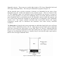
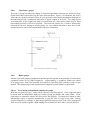
Should a liquefied gas be spilled in an open space, the liquid will rapidly evaporate to produce
a vapour cloud which will be gradually dispersed downwind. The vapour cloud or plume
would be flammable only over part of its downwind travel. The situation is illustrated in
general terms in Figure 2.11. The region B immediately adjacent to the spill area A would be
non-flammable because it is over-rich, i.e. it contains too low a percentage of oxygen to be
flammable. Region D would also be non-flammable because it is too lean, i.e. it contains too
little vapour to be flammable. The flammable zone would be between these two regions as
indicated by C.
Figure 2.11 Flammable vapour zones emanating from a liquefied gas spill
Saturated hydrocarbons
2.2.5
The saturated hydrocarbons methane, ethane, propane and butane are all colourless and
odourless liquids under normal conditions of carriage.
They are all flammable gases and will burn in air and/or oxygen to produce carbon dioxide and
water vapour. As they are chemically non-reactive they do not present chemical compatibility
problems with materials commonly used in handling. In the presence of moisture, however, the
saturated hydrocarbons may form hydrates.
Sulphur compounds such as mercaptans are often added as odourisers prior to sale to aid in the
detection of these vapours. This process is referred to as "stenching".
2.2.6
Unsaturated hydrocarbons
The unsaturated hydrocarbons ethylene, propylene, butylene, butadiene and isoprene are
colourless liquids with a faint, sweetish characteristic odour. They are, like the saturated
hydrocarbons, all flammable in air and/or oxygen, producing carbon dioxide and water vapour.
They are chemically more reactive than the saturated hydrocarbons and may react dangerously
with chlorine. Ethylene, propylene and butylene do not present chemical compatibility
problems with materials of construction, whereas butadiene and isoprene, each having two
pairs of double bonds, are by far the most chemically reactive within this family group. They
may react with air to form peroxides which are unstable and tend to induce polymerisation.
Butadiene is incompatible in the chemical sense with copper, silver, mercury, magnesium and
aluminium. Butadiene streams often contain traces of acetylene, which can react to form
explosive acetylides with brass and copper.
Water is soluble in butadiene, particularly at elevated temperatures and Figure 2.12 illustrates
this effect. The figures quoted are for the purpose of illustration only. On cooling watersaturated butadiene the solubility of the water decreases and water will separate out as droplets,
which will settle as a layer in the bottom of the tank. For instance, on cooling water-saturated
butadiene from + 15oC to + 5oC approximately 100 ppm of free water would separate out. On
this basis, for a 1,000 3m tank, 100 3dm of free water would require to be drained from the
bottom of the tank. On further cooling to below 0 oC this layer of water would increase in
depth and freeze.
Figure 2.12 The solubility of water in butadiene
2.2.7
Chemical gases
The chemical gases commonly transported in liquefied gas carriers are ammonia, vinyl chloride
monomer, ethylene oxide, propylene oxide and chlorine. Since these gases do not belong to
one particular family their chemical properties vary.
Liquid ammonia is a colourless alkaline liquid with a pungent odour. The vapours of
ammonia are flammable and burn with a yellow flame forming water vapour and nitrogen,
however, the vapour in air requires a high concentration (16-25 per cent) to be flammable, has a
high ignition energy requirement (600 times that for propane) and burns with low combustion
energy. For these reasons the IMO Codes, while requiring full attention to the avoidance of
ignition sources, do not require flammable gas detection in the hold or interbarrier spaces of
carrying ships. Nevertheless, ammonia must always be regarded as a flammable cargo.
Ammonia is also toxic and highly reactive. It can form explosive compounds with mercury,
chlorine, iodine, bromine, calcium, silver oxide and silver hypochlorite. Ammonia vapour is
extremely soluble in water and will be absorbed rapidly and exothermically to produce a
strongly alkaline solution of ammonium hydroxide. One volume of water will absorb
approximately 200 volumes of ammonia vapour. For this reason it is extremely undesirable to
introduce water into a tank containing ammonia vapour as this can result in a vacuum condition
rapidly developing within the tank.
Since ammonia is alkaline, ammonia vapour/air mixtures may cause stress corrosion. Because
of its highly reactive nature copper alloys, aluminium alloys, galvanised surfaces, polyvinyl
chloride, polyesters and viton rubbers are unsuitable for ammonia service. Mild steel, stainless
steel, neoprene rubber and polythene are, however, suitable.
Vinyl chloride monomer (VCM) is a colourless liquid with a characteristic sweet odour. It is
highly reactive, though not with water, and may polymerise in the presence of oxygen, heat and
light. Its vapours are both toxic and flammable. Aluminium alloys, copper, silver, mercury
and magnesium are unsuitable for vinyl chloride service. Steels are, however, chemically
compatible.
Ethylene oxide and propylene oxide are colourless liquids with an ether-like odour. They are
flammable, toxic and highly reactive. Both polymerise, ethylene oxide more readily than
propylene oxide, particularly in the presence of air or impurities. Both gases may react
dangerously with ammonia. Cast iron, mercury, aluminium alloys, copper and alloys of
copper, silver and its alloys, magnesium and some stainless steels are unsuitable for the
handling of ethylene oxide. Mild steel and certain other stainless steels are suitable as materials
of construction for both ethylene and propylene oxides.
Chlorine is a yellow liquid, which evolves a green vapour. It has a pungent and irritating
odour. It is highly toxic but is non-flammable though it should be noted that chlorine can
support combustion of other flammable materials in much the same way as oxygen. It is
soluble in water forming a highly corrosive acid solution and can form dangerous reactions
with all the other liquefied gases. In the moist condition, because of its corrosivity, it is
difficult to contain. Dry chlorine is compatible with mild steel, stainless steel, monel and
copper. Chlorine is very soluble in caustic soda solution, which can be used to absorb chlorine
vapour.
2.2.8
Toxicity
Toxicity is the ability of a substance to cause damage to living tissue, impairment of central
nervous system, illness or, in extreme cases, death when ingested, inhaled or absorbed through
the skin. Exposure to toxic substances may result in one or more of the following effects.
i)
i)
Irritation of the lungs and throat, of the eyes and sometimes of
the skin. Where irritation occurs at comparatively low levels of exposure, it may serve as
a warning which must always be obeyed. However, this cannot be relied upon since some
substances have other toxic effects before causing appreciable irritation.
ii)
ii)
Narcosis, which results in interference with or inhibition of
normal responses and control. Sensations are blunted, movements become clumsy and
reasoning is distorted. Prolonged and deep exposure to a narcotic may result in
anaesthesia (loss of consciousness). While a victim removed from narcotic exposure will
generally fully recover, the danger is that while under the influence he will not respond to
normal stimuli and be oblivious of danger.
iii)
Short or long term or even permanent damage to the body tissue
iii)
or nervous system. With some chemicals this may occur
at low levels of
concentration if exposure is prolonged and frequent.
2.2.9
Threshold Limit Values (TLV)
As a guide to permissible vapour concentrations for prolonged exposure, such as might occur in
plant operation, various governmental authorities publish systems of Threshold Limit Value
(TLV) for the toxic substances most handled by industry. The most comprehensive and widely
quoted system is that published by the American Conference of Governmental and Industrial
Hygienists (ACGIH). The recommended TLVs are updated annually in the light of experience
and increased knowledge.
The ACGIH system contains the following three categories of TLV in order adequately to
describe the airborne concentrations to which it is believed that personnel may be exposed over
a working life without adverse effects. TLV systems promulgated by advisory bodies in other
countries are generally similar in structure.
A)
TLV-TWA. Time weighted average concentration for an 8
A)
hour day or 40 hour week throughout working life.
B)
TLV-STEL. Short term exposure limit in terms of the
B)
maximum concentration allowable for a period of up to 15 minutes duration provided
there are no more than 4 such excursions per day and at least 60 minutes between
excursions.
C)
C)
TLV-C. The ceiling concentration, which should not be
exceeded even instantaneously. While most substances that are quoted are allocated a
TLV-TWA and a TLV-STEL, only those which are predominantly fast-acting are given a
TLV-C.
TLV are usually given in ppm (parts of vapour per million parts of contaminated air by
volume) but may be quoted in mg/r& (milligrams of substance per cubic metre of air). Where a
TLV is referred to but without the indications TWA, STEL or C, it is the TLV-TWA which is
meant. However, TLV should not be regarded as sharp dividing lines between safe and
hazardous concentrations and it must always be best practice to keep concentrations to a
minimum regardless of the published TLV. TLVs are not fixed permanently but are subject to
revision. The latest revision of these values should always be consulted. TLV presently quoted
by ACGIH for some of the liquefied gases are given in Table 9.1 by way of illustration but it
must be appreciated that the application of TLV to a specific work situation is a specialist
matter.
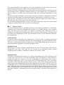
2.3
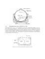
METHODS OF LIQUEFACTION
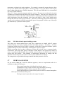
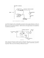
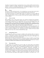
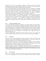
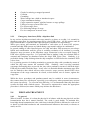
2.3.1
Evaporation
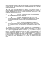
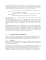
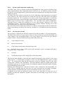
A liquid change to gas is called evaporation. This
may happen by evaporation or boiling. To achieve
evaporation, heat of evaporation is needed. Some
G as
liquids evaporate very quickly, such as gasoline
and ether. Other liquid substances evaporate very
slowly, such as in crude oil. Evaporation is vapour
formed out of the liquid surface and occurs at all
temperatures.
This is explained by some of the liquid’s surface
molecules being sent into the air, which is
strongest at high temperatures, dry air and fresh
F luid
wind. The specific temperature calls the amount of
heat needed for one kilo of liquid with fixed
temperature to form into one kilo of steam with
the same temperature”. The heat from evaporation
is set free when the steam forms to liquid again, or condenses.
The heat necessary to evaporate one kilo of a certain liquid is called “specific heat of
evaporation”, abbreviated as (r). The unit for specific heat of evaporation is J/kg.
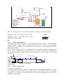
2.3.2
Boiling
Boiling is steam formed internally in the liquid. The boiling occurs at a certain temperature,
called “the boiling point”. Water is heated in normal atmospheric pressure (1 atm), in an open
container. In common, some parts of air are always dissolved. The rise in temperature is read
from a thermometer placed in the liquid’s surface. When the temperature has reached 100oC,
steam bubbles will form inside the liquid substance, especially in the bottom of the container.
With continuous heat supply, the bubbling will rise like a stream towards the surface and
further up into the air. The water is boiling.
The formation of bubbling steam can be explained as follows:
During the heating, the water molecule’s kinetic energy increases, consequently the molecules
demand more space. During the boiling, as long as there is water in the container, the
temperature will be 100oC.
The boiling point is dependent upon the pressure. If the steam or the atmospheric pressure
increases above liquid substance, the boiling point will also rise. If the surface temperature is
just below the boiling temperature, then the water steam will evaporate on the surface. The
evaporation point and the boiling point will be the same accordingly.
The pressure from the surrounding liquid is the total amount of pressure above the liquid, Pa,
plus the static liquid pressure.
pa
P = Pa + (ρ x g x h )
P = pressure in Pascal (100 000 Pa + 1 bar)
Pa = barometer pressure
ρ = the liquid density in kg/m3
g = force of gravity acceleration (9,81m/s2)
h
h = liquid column in meter.
p = pa + (ρ x g x h)
p
When reducing the pressure above the liquid, the
boiling point will also be reduced. A practical use
of this characteristic is the production of fresh water on board (fresh water generator).
2.3.3
Condensation
Condensation is the opposite of evaporation. If a gas is to be changed to liquid at the same
temperature, we must remove the heat of evaporation from the gas. A gas can be condensed at
all temperatures below the critical temperature. By cooling a gas, the molecule speed decreases
hence the kinetic speed. The internal energy decreases, as well as, the molecule units and liquid
forms.
2.3.4
Distillation
Distillation is a transferring of liquid to vapour, hence the following condensing of vapour to
liquid. Substances, which were dissolved in the liquid, will remain as solid substance. With
distillation it is possible to separate what has been dissolved from the substance, which was
being dissolved. When a mixture of two liquids with different boiling point is heated, will the
most volatile liquid evaporate first while the remaining becomes richer on the less volatile? On
board, for instance, seawater is distillated by use of an evaporator.
2.3.5
Saturated, Unsaturated or Superheated Steam
Let us imagine boiling water, releasing vapour from a container, leading the steam into a
cylinder that is equipped with a tightening piston, a manometer and two valves. The steam
flows through the cylinder and passes the valves, whereon the valves are closing. There now is
a limited and fixed volume of steam in the cylinder. Around this cylinder a heating element is
fitted. Vapour from the container is constantly sent through this heating element to ensure that
the temperature is maintained constant.
The piston is pressed inwards, and now the manometer should show a rise in pressure. But, the
manometer shows an unchanged pressure regardless how much the volume is reduced. What’s
happening is, the further the piston is pressed inwards, some parts of the steam is condensed
more using less volume. The vapour from the heating element removes the condensed heat,
which is liberated during the condensation process.
We find that the amount of steam, which is possible to contain per volume unit, remains
constant when the steam’s temperature is equal to the condensation point at the set pressure.
The room cannot absorb more vapour, it is saturated with steam and called “saturated”. If the
piston is pressed outwards, the pressure will still show constant. The conclusion is:
With temperature equal to the condensation point by set pressure, steam is
saturated.
Steam above boiling water is saturated.
Saturated steam with a set temperature has a set pressure. This is called
saturation pressure.
With constant temperature saturated steam cannot be compressed.
This also concerns vapour as saturated steam of other gases. Using the same cylinder
arrangement as before.
The cylinder contains saturated steam, no water. The piston is drawn outward. When no water
exists over the piston no new steam will be supplied underneath. The manometer will now
show reduced (falling) pressure as the steam expands. When saturated steam expands without
supplying new steam, it is called unsaturated steam. The room has capacity to collect more
steam.
Unsaturated steam contains lower pressure than saturated steam at the same temperature. The
unsaturated steam in the cylinder can be made saturated again in two ways. Either by pushing
the piston inward to the originated position, or let the unsaturated steam be sufficiently cooled
down. When the temperature is reduced, the saturation pressure will reduce. Unsaturated steam
will, in other words, have a too high temperature to be saturated with the temperature it
originally had. Therefore, this often is referred to as superheated steam.
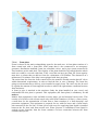
2.4
HAZARDS FROM LIQUEFIED GAS
This section deals with the properties common to all or most bulk liquefied gas cargoes. These
cargoes are normally carried as boiling liquids and, as a consequence, readily give off vapour.
The common potential hazards and precautions are highlighted in the following sections.
2.4.1
Flammability
Almost all cargo vapours are flammable. When ignition occurs, it is not the liquid which burns
but the evolved vapour. Different cargoes evolve different quantities of vapour, depending on
their composition and temperature.
Flammable vapour can be ignited and will burn when mixed with air in certain proportions. If
the ratio of vapour to air is either below or above specific limits the mixture will not burn. The
limits are known as the lower and upper flammable limits, and are different for each cargo.
Combustion of vapour/air mixture results in a very considerable expansion of gases which, if
constricted in an enclosed space, can raise pressure rapidly to the point of explosive rupture.
2.4.2
Toxicity
Some cargoes are toxic and can cause a temporary or permanent health hazard, such as
irritation, tissue damage or impairment of faculties. Such hazards may result from skin or
open-wound contact, inhalation or ingestion.
Contact with cargo liquid or vapour should be avoided. Protective clothing should be worn as
necessary and breathing apparatus should be worn if there is a danger of inhaling toxic vapour.
The toxic gas detection equipment provided should be used as necessary and should be
properly maintained.
2.4.3
Asphyxia
Asphyxia occurs when the blood cannot take a sufficient supply of oxygen to the brain. A
person affected may experience headache, dizziness and inability to concentrate, followed by
loss of consciousness. In sufficient concentrations any vapour may cause asphyxiation,
whether toxic or not.
Asphyxiation can be avoided by the use of vapour and oxygen detection equipment and
breathing apparatus as necessary.
2.4.4
Anaesthesia
Inhaling certain vapours (e.g ethylene oxide) may cause loss of consciousness due to effects
upon the nervous system. The unconscious person may react to sensory stimuli, but can only
be roused with great difficulty.
Anaesthetic vapour hazards can be avoided by the use of cargo vapour detection equipment and
breathing apparatus as necessary.
2.4.5
Frostbite
Many cargoes are either shipped at low temperatures or are at low temperatures during some
stage of cargo operations. Direct contact with cold liquid or vapour or uninsulated pipes and
equipment can cause cold burns or frostbite. Inhalation of cold vapour can permanently
damage certain organs (e.g. lungs).
Ice or frost may build up on uninsulated equipment under certain ambient conditions and this
may act as insulation. Under some conditions, however, little or no frost will form and in such
cases contact can be particularly injurious.
Appropriate protective clothing should be worn to avoid frostbite, taking special care with drip
trays on deck which may contain cargo liquid.
2.4.6
Comparison of hazards in liquefied gas carriage and in the transport of normal
petroleum
While the carriage of liquefied gases incurs its own special hazards, some of its features are
less hazardous than those of the heavier petroleum. The following is a brief summary.
Hazards peculiar to carriage of liquefied gases:
(a)
Cold from leaks and spillages can affect the strength and ductility of ship's structural
steel.
(b)
Contact by personnel with the liquids, or escaping gases, or with cold pipework can
produce frost burns.
(c)
Rupture of a pressure system containing LPG could release a massive evolution of
vapour.
Features of liquefied gas carriage resulting in a reduction of hazard compared with normal
tanker operation:
(i)
Loading or ballasting do not eject gases to atmosphere in vicinity of decks and
superstructures. Gas-freeing is rarely performed and does not usually produce gas on
deck.
(ii)
Liquefied gas compartments are never flammable throughout the cargo cycle. Static
electricity and other in-tank ignition sources are therefore no hazard.
(iii)
There is no requirement for tank cleaning and its associated hazards.
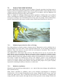
3 CARGO CONTAINMENT SYSTEMS
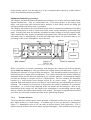
3.1
INDEPENDENT TANKS
These types of tanks are completely self-supporting and do not form part of the ship’s hull and
do not contribute to the hull strength. Depending mainly on design pressure, there are three
different types of independent tanks for gas carriers, Types A, B and C
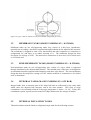
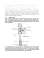
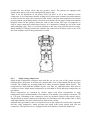
3.1.1
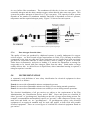
Independent tanks, type A (MARVS < 0. 7 bar)
Independent tanks of type A are prismatic and supported on insulation-bearing blocks and
located by anti-roll chocks and anti-flotation chocks. The tanks are normally divided along
their centreline by a liquid-tight bulkhead; by this feature, together with the chamfered upper
part of the tank, the free liquid surface is reduced and the stability is increased. When these
cargo tanks are designed to carry LPG (at -50oC), the tank is constructed of fine-grained lowcarbon manganese steel.
The Conch design has been developed for carriage of LNG (at-163oC). The material for these
cargo tanks has to be either 9% nickel steel or aluminium.
Figure 3.1 Prismatic self-supporting Type A tank for a fully refrigerated LPG carrier
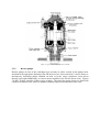
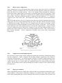
3.1.2
Independent tanks, type B (MARVS < 0. 7 bar)
Independent tanks of type B are normally spherical and welded to a vertical cylindrical skirt,
which is the only connection to the ship's hull. The hold space in this design is normally filled
with dry inert gas but may be ventilated with air provided that inerting of the spaces can be
achieved in the event of the vapour detection system detecting cargo leakage. A protective steel
dome covers the primary barrier above deck level, and insulation is applied to the outside of the
primary barrier surface. This containment system has been used for carriage of LNG. The
material of construction is either 9% nickel steel or aluminium.
Figure 3.2 Self-supporting spherical Type B tank
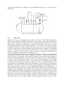
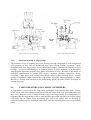
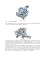
3.1.3
Independent tanks, type C (MAR VS< 0. 7 bar)
Independent tanks of type C are cylindrical pressure tanks mounted horizontally on two or
more cradle-shaped foundations. The tanks may be fitted on, below or partly below deck and
be both longitudinally and transversely located. To improve the poor utilization of the hull
volume, lobe-type tanks are commonly used at the forward end of the ship. This containment
system is used for LPG and LEG. The material, if used for the construction of tanks designed
to carry ethylene, is 5% nickel steel.
Figure 3.3 Type C tanks as found on fully pressurised gas carriers
Figure 3.4 Type C tanks as utilised on semi-pressured/fully refrigerated gas carriers
3.2
MEMBRANE TANKS (MARVS NORMALLY < 0.25 BAR)
Membrane tanks are not self-supporting tanks; they consist of a thin layer (membrane),
normally not exceeding 1 mm thick, supported through insulation by the adjacent hull structure.
The membrane is designed in such a way that thermal and other expansion or contraction is
compensated for, and there is no undue stressing of it. The membrane design has been
developed for carriage of LNG. The material of construction is lnvar steel (36% nickel steel)
or 9% nickel steel.
3.3
SEMI-MEMBRANE TANKS (MARVS NORMALLY < 0.25 BAR)
Semi-membrane tanks are not self-supporting; they consist of a layer which is supported
through insulation by the adjacent hull structure. The rounded parts of the layer are designed to
accommodate thermal expansion and contraction, and other types thereof. The semi-membrane
design has been developed for carriage of LNG, and the material of construction is 9% nickel
steel or aluminium.
3.4
INTEGRAL TANKS (MA RVS NORMALLY< 0.25 BAR)
Integral tanks form a structural part of the ship's hull and are influenced by the same loads
which stress the adjacent hull structure, and in the same manner. This form of cargo
containment is not normally allowed if the cargo temperature is below -1 0 OC. Today, this
containment system is partly used on some LPG ships dedicated to the carriage of butane.
3.5
INTERNAL INSULATION TANKS
Thermal insulation must be fitted to refrigerated cargo tanks for the following reasons:
a) a) To minimise heat flow into cargo tanks and thus reduce boil-off.
b) b) To protect the general ship structure around the cargo tanks from the effects of low
temperature
For use aboard gas carriers insulation materials should process the following characteristics:
i)
i)
Low thermal conductivity.
ii)
ii)
Non-flammable or self-extinguishing.
iii)
iii)
Ability to bear loads.
iv)
iv)
Ability to withstand mechanical damage.
v)
v)
Light weight.
vi)
vi)
Material should not be affected by cargo liquid or vapour
The material’s vapour-sealing properties to prevent ingress of water or water vapour is very
important. Not only can ingress of moisture result in loss of insulation efficiency but
progressive condensation and freezing can cause extensive damage to the insulation. Humidity
conditions must therefore be kept as low as possible in hold spaces.
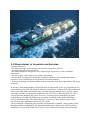
4 THE LIQUEFIED GAS TANKER
4.1
GAS TANKER TYPES
Gas carriers can be grouped into six different categories according to the cargo carried and the
carriage condition, i.e.
(a)
Fully pressurised ships
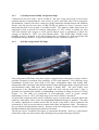
(b)
Semi-refrigerated/semi-pressurised ships
(c)
Semi-pressurised/fully refrigerated ships
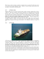
(d)
Fully refrigerated LPG ships
(e)
Ethylene ships
(f)
LNG ships
Ship types (a), (b) and (c) are most suitable for the shipment of smaller-size cargoes of LPG
and chemical gases on short-sea and near-sea routes whereas ship type (d) is used extensively
for the carriage of large-size cargoes of LPG and ammonia on the deep-sea routes.
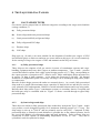
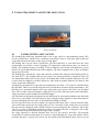
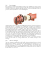
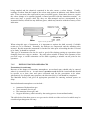
4.1.1
(a) Fully pressurised ships
These ships are the simplest of all gas carriers in terms of containment systems and cargohandling equipment and carry their cargoes at ambient temperature. Type C tanks - pressure
vessels fabricated in carbon steel with a typical design pressure of 17.5 barg, corresponding to
the vapour pressure of propane at 45oC, must be used. Ships with higher design pressures are
in service: 18 barg is quite common - a few ships can accept up to 20 barg. No thermal
insulation or reliquefaction plant is necessary and cargo can be discharged using either pumps
or compressors.
Because of their design pressure the tanks are extremely heavy. As a result, fully pressurised
ships tend to be small with maximum cargo capacities of about 4,000 m3 and they are used to
carry primarily LPG and ammonia. Ballast is carried in double bottoms and in top wing tanks.
Because these ships utilise Type C containment systems, no secondary barrier is required and
the hold space may be ventilated with air. Figure 3.3 shows a section through a typical fully
pressurised ship.
4.1.2
(b) Semi-refrigerated ships
These ships are similar to fully pressurised ships in that they incorporate Type C tanks - in this
case pressure vessels designed typically for a maximum working pressure of 5-7 barg. The
ships range in size up to 7,500 m3 and are primarily used to carry LPG. Compared to fully
pressurised ships, a reduction in tank thickness is possible due to the reduced pressure, but at
the cost of the addition of refrigeration plant and tank insulation. Tanks on these ships are
constructed of steels capable of withstanding temperatures as low as –10oC. They can be
cylindrical, conical or spherical in shape.
(c) Semi-pressurised/fully refrigerated ships
4.1.3
Constructed in the size range 1,500 to 30,000 m3, this type of gas carrier has evolved as the
optimum means of transporting the wide variety of gases, from LPG and VCM to propylene
and butadiene, found in the busy coastal gas trades around the Mediterranean and Northern
Europe. Like the previous two types of ship, SP/FR gas tankers use Type C pressure vessel
tanks and therefore do not require a secondary barrier. The tanks are made either from low
temperature steels to provide for carriage temperatures of –48oC which is suitable for most
LPG and chemical gas cargoes or from special alloyed steels or aluminium to allow the
carriage of ethylene at –104oC (see also ethylene ships). The SP/FR ship's flexible cargo
handling system is designed to be able to load from, or discharge to, both pressurised and
refrigerated storage facilities. A typical SP/FR ship section is shown in Figure 3.4.
4.1.4
(d) Fully refrigerated LPG ships
Fully refrigerated (FR) ships carry their cargoes at approximately atmospheric pressure and are
generally designed to transport large quantities of LPG and ammonia. Four different cargo
containment systems have been used in FR ships: independent tanks with double hull,
independent tanks with single side shell but double bottom and hopper tanks, integral tanks and
semi-membrane tanks, both these latter having a double hull. The most widely used
arrangement is the independent tank with single side shell with the tank itself a Type A
prismatic free-standing unit capable of withstanding a maximum working pressure of 0.7 barg
(Figure 3.1). The tanks are constructed of low-temperature steels to permit carriage
temperatures as low as –48oC. FR ships range in size from 10,000 to 100,000 m3.
A typical fully refrigerated LPG carrier would have up to six cargo tanks, each tank fitted with
transverse wash plates, and a centre line longitudinal bulkhead to improve stability. The tanks
are usually supported on wooden chocks and are keyed to the hull to allow expansion and
contraction as well as prevent tank movement under static and dynamic loads. The tanks are
also provided with anti-flotation chocks. Because of the low-temperature carriage conditions,
thermal insulation and reliquefaction plant must be fitted.
The FR gas carrier is limited with respect to operational flexibility. However, cargo heaters
and booster pumps are often used to allow discharge into pressurised storage facilities.
Where Type A tanks are fitted, a complete secondary barrier is required. The hold spaces must
be inerted when carrying flammable cargoes. Ballast is carried in double bottoms and in topside tanks or, when fitted, side ballast tanks.
4.1.5
(e) Ethylene ships
Ethylene ships tend to be built for specific trades and have capacities ranging from 1,000 to
30,000 m3. This gas is normally carried fully refrigerated at its atmospheric pressure boiling
point of –104oC. If Type C pressure vessel tanks are used, no secondary barrier is required;
Type B tanks require a partial secondary barrier; Type A tanks require a full secondary barrier
and because of the cargo carriage temperature of –104oC the hull cannot be used as a secondary
barrier, so in this case a separate secondary barrier must be fitted. Thermal insulation and a
high capacity reliquefaction plant are fitted on this type of vessel.
As mentioned, many ethylene carriers can also carry LPG cargoes thus increasing their
versatility. Ballast is carried in the double bottom and wing ballast tanks and a complete
double hull are required for all cargoes carried below –55oC whether the tanks are of Type A, B
or C.
4.1.6
(f) LNG ships
LNG carriers are specialised vessels built to transport large volumes of LNG at its atmospheric
pressure boiling point of –163oC. These ships are now typically of between 120,000 and
130,000 M3 capacity and are normally dedicated to a specific project where they will remain
for their entire contract life, which may be between 20-25 years. Apart from a few notable
exceptions built during the early years of LNG commercial transportation these ships are of
three types: (1) Gaz Transport membrane (Figure 4.1), (2) Technigaz membrane (Figure 4.2)
and (3) Kvaerner Moss spherical independent Type B (Figure 4.3).
All LNG ships have double hulls throughout their cargo length, which provides adequate space
for ballast; the membranes have a full secondary barrier, the spheres a drip-pan type protection.
Another characteristic common to all is that they burn the cargo boil-off as fuel (permitted with
methane cargo, being lighter than air at ambient temperature - but not propane or butane which
are heavier than air gases).
Figure 4.1 Gaz Transport membrane containment systems as utilised on larger-sized LNG carriers
Hold spaces around the cargo tanks are continuously inerted except in the case of spherical
Type B containment where hold spaces may be filled with dry air provided that there are
adequate means for inerting such spaces in the event of cargo leakage being detected.
Continuous gas monitoring of all hold spaces is required.
Figure 4.2 (a) Technigaz membrane containment system as utilised on larger LNG carriers
To date, reliquefaction plants have not been fitted to LNG vessels because, being a much colder
cargo than LPG, the necessary equipment is much more costly and it has been more economic
to burn the boil-off gas in steam turbine propulsion plants. However, due to the rising cost of
oil fuel and increasing value accredited to LNG, future designs of LNG ships tend towards the
provision of greater tank insulation (to reduce boil-off), a reliquefaction plant and diesel
engined main propulsion.
Figure 4.2 (b) Detail of the Technigaz membrane’s barrier and insulation construction
4.2
LAYOUT OF A GENERAL GAS CARRIER
Liquefied Gas tankers are designed, built and operated so they obey rules and regulations.
These rules and regulations are defined by the Governments of the countries in which the ships
are registered, and are based on rules made Internationally and recommended by IMO. The
rules are strictly applied, and ships are inspected throughout the world to make sure that they
conform. These rules protect you, the ship, the environment and the cargo, and help to make the
operation safe.
It is not permitted for a cargo pump-room to be placed below the upper deck; nor may cargo
pipework be run beneath deck level; therefore deepwell or submersible pumps must be used for
cargo discharge. Cargo pipework to tanks beneath deck level must be taken through a cargo
tank dome, which penetrates the deck.
Where a gas tanker is fitted with a reliquefaction plant, this plant is housed in a compressor
house on deck. Contiguous to this compressor house is an electric motor room, which contains
the motors for driving the compressors of the reliquefaction plant and booster pumps when
fitted. A gastight bulkhead must separate the electric motor room and compressor room.
The IMO codes detail the requirements for mechanical ventilation of these rooms. Positive
pressure ventilation must be provided for the electric motor room with negative pressure
ventilation for the cargo compressor area, thus ensuring a positive pressure differential between
the rooms. An airlock entrance to the electric motor room from the weather deck, with two
gastight doors at least 1.5 metres apart, prevents loss of this pressure differential on entry into
the motor room. To ensure that both doors are not opened simultaneously they must be selfclosing with audible and visual alarms on both sides of the airlock. In addition, loss of overpressure in the motor room should trip the electric motors within. The importance of these
protective systems is fundamental to the safety of the gas tanker. Another safety feature
associated with the motor/compressor room area concerns sealing of the driving shafts
penetrating the gastight bulkhead between the compressor and motor room.
The cargo tanks cannot be used for ballast purposes on gas carriers and therefore separate
ballast tanks are required.
The cargo containment and handling systems must be completely separate from
accommodation spaces, machinery spaces, etc., with cofferdam separation or other means of
gastight segregation between the cargo area and the engine room, fuel tanks and chain lockers.
The IMO codes also give specific recommendations for positioning of doors leading from
accommodation spaces into cargo areas. In addition, air intakes for accommodation and engine
spaces must be sited at a minimum distance from ventilation outlets associated with gas
dangerous areas. All air intakes into accommodation and service spaces should be fitted with
closing devices.
Gas tankers are fitted with a fixed water spray system for fire protection purposes. This covers
cargo tank domes, cargo tank areas above deck, manifold areas, the front of the accommodation
area, boundaries of control rooms facing the cargo area, etc. Minimum water flow rates of 10
litre/m2 per minute for horizontal surfaces and 4 litre/m2 per minute for vertical surfaces should
be achieved. In addition to this fixed water spray system, all gas tankers must be fitted with a
fixed dry powder installation capable of fighting local cargo area fires. At least two hand hose
lines must be provided to cover the deck area. The dry powder installation is activated by
nitrogen, which is stored in pressure vessels adjacent to the powder containers.
4.3
SURVIVAL CAPABILITY AND TANK LOCATION
The IMO codes divide gas carriers into four categories, ship types IG, IIG, IIPG and IIIG,
which reflect the hazard rating of the cargoes to be carried. For example, Type IG ships, where
the cargo tanks are located at the greatest distance from the side shell (and may also be
restricted in capacity), must be used for cargoes representing the greatest hazard, eg., chlorine.
Ship types IIG/IIPG and IIIG can carry cargoes which represent progressively decreasing
environmental hazards and therefore progressively less stringent constructional requirements in
respect of damage survival capability in the event of collision or grounding.
A fully refrigerated ship, say with Type A tanks, designed for LPG must comply with the
requirements for tank location and survival capability of a category IIG ship whereas a semirefrigerated ship with Type C tanks carrying LPG can comply with the requirements either of a
IIG or a IIPG ship. For the latter case the Type C pressure vessels must be designed for a
design vapour pressure of at least 7 barg, and a design temperature of not lower than –55oC.
The IIPG category takes into account the fact that the pressure vessel design provides increased
survival capability when the ship is damaged by collision or grounding.
The IMO codes and classification rules should be referred to for the detailed construction
requirements for each category of ship.
5 CARGO EQUIPMENT AND INSTRUMENTATION
“Norgas Challenger”
5.1
TANKS, PIPING AND VALVES
The loading lines and pipes mentioned here refer to gas carrier’s cargo handling system. This
involves liquid lines, vapour lines, condensate return lines, lines to vent mast, pipes inside the
cargo tank and seawater pipes to the cargo cooling plant.
All loading lines on gas carrier: liquid lines, gas lines and lines to vent mast have the same
requirements as pressure vessels regarding of temperature and pressure they are meant to
handle. All welding on pipes exceeding 75 mm in diameter and 10 mm wall thickness or more
must be X-rayed and classed by the class company. The same regulation do we have on flanges
and spool pieces also.
All loading lines outside the cargo tank must be produced by material with melting point no
less than 925oC. The loading lines on gas carriers are mostly produced of stainless steel, but
low temperature nickel steel is also in use. All loading lines with an outside diameter of 25 mm
or more must be flanged or welded. Otherwise, lines with an outside diameter less than 25 mm
can be connected with treads.
Loading lines designed for cargo with low temperature, less than –10oC must be insulated from
the ship hull. This to prevent the ship hull to be cooled down to below design temperature. The
hull has to be protected against cold cargo spill under spool pieces and valves on all liquid
lines. This is done with wood planks or plywood. To prevent cold cargo spill on the hull plates,
a drip tray must be placed under the manifold flanges.
All lines that are thermally insulated from the hull must be electrically bonded to the hull with
steel wire or steel bands. On each flange on lines and pipes where gaskets is used, there must be
electrical bonding with steel wire or steel band from flange to flange.
On all cargo lines where it can be liquid it is required with safety valve. Vapour from the safety
valve outlet must go back to the cargo tank or to the vent mast. If the return goes to vent mast
the pipe must be equipped with a liquid collector to prevent liquid to the vent mast. The safety
valve’s set point is dependent upon the pressure for which the line is designed. The safety
valves must be tested and sealed by the ship Class Company.
No cargo pipework is allowed beneath deck level on gas carriers; therefore, all pipework
connections to tanks beneath deck level must be taken through the cargo tank domes, which
penetrate the deck. Vapour relief valves are also fitted on the tank domes; these relieve to vent
stacks whose height and safe distances from accommodation spaces etc. are specified in the
IMO Codes.
Figure 5.1 Cargo tank dome piping arrangement
Cargo valves
5.1.1
Isolating valves for gas carriers must be provided in accordance with the IMO requirements.
Where cargo tanks have a MARVS greater than 0.7 barg (Type C cargo tanks), all main and
liquid vapour connections (except relief valve connections) should normally be fitted with a
double valve arrangement comprising a manually operated globe valve with a remotely
operated isolation valve in series with this manual valve. For Types A and B cargo tanks with
the MARVS less than 0.7 barg the IMO Codes allow shut-off valves for liquid and vapour
connections which can be remotely actuated but which must also be capable of local manual
operation. Remotely operated emergency shutdown valves are provided at the liquid and
vapour crossovers for all gas carriers. Figure 5.1 shows the cargo tank dome piping and
valving arrangement for a typical semi-refrigerated vessel.
At several locations around the ship, e.g. bridge front, gangway, compressor room and cargo
control room, emergency control stations, pneumatic vent valves or electric push buttons are
provided which, when operated, close remotely actuated valves and stop cargo pumps and
compressors where appropriate - effectively creating a "dead ship" as far as cargo-handling is
concerned. Emergency shut down (ESD) is also required to be automatic upon loss of electric
or control power, valve actuator power or fire at tank domes or manifold where fusible
elements are suitably situated to actuate the ESD signal system. Individual tank filling valves
are required to be automatically closed upon the actuation of an overfill sensor in the tank to
which they are connected. ESD valves may be either pneumatically or hydraulically operated
but in either case must be "fail safe", i.e. close automatically upon loss of actuating power.
The possibility of surge pressure generation when the ship's ESD system is actuated during
loading is a vital consideration. The situation varies from terminal to terminal and is a function
of the loading rate, the length of the pipeline at the terminal, the rate of closure of the valve and
the valve characteristic itself. The phenomenon of surge pressure generation is complex and its
effects can be extreme, such as the rupture of hoses or hard arm joints. Precautions may
therefore be necessary to avoid the possibility of damage. Terminals may need to check ships'
ESD valve closure rates and adjust loading rates accordingly or place on board a means
whereby the ship may actuate the terminal ESD system and so halt the flow of cargo before the
ship's ESD valves start to close. NOTE: Consultation between the ship and shore must always
take place in order to establish the parameters relevant to surge pressure generation and to
agree upon a safe loading rate.
The types of isolation valve normally found on gas tankers are ball, globe, gate or butterfly
valves. These valves are usually fitted with pneumatic or, occasionally, hydraulic actuators.
Ball valves for LNG and Ethylene service are provided with some means of internal pressure
relief; usually, a hole is drilled between the ball cavity and downstream side of the valve.
Valves must be of the fire safe type.
Strainers are normally provided at the manifold connections for loading/ discharging. It is
important not to bypass these strainers and to ensure they are frequently checked and cleaned.
The strainers are installed to protect cargo handling plant and equipment from damage by
foreign objects. Many strainers are designed for one-way flow only.
5.2
PRESSURE-RELIEF AND VACUUM PROTECTION SYSTEM
The IMO Codes require at least two pressure relief valves of equal capacity to be fitted to any
cargo tank of greater than 20 M3 capacity. Below this capacity one is sufficient. The types of
valves normally fitted are either spring-loaded or pilot-operated relief valves. Pilot-operated
relief valves may be found on Types A, B and C tanks while spring-loaded relief valves are
usually only used on Type C tanks. The use of pilot-operated relief valves on Type A tanks
ensures accurate operation at the low pressure conditions prevailing while their use on Type C
tanks, for example, allows variable relief settings to be achieved using the same valve.
Changing the pilot spring may do this. Figure 5.2 shows a typical pilot-operated relief valve of
this type. Other types of pilot valve are available for adjustment of “set pressure” and “blow
down pressure”.
Figure 5.2 Pilot operated relief valve
Adjustable setting of pilot operated relief valves, where provided, are used mainly in two
different roles. Firstly, they may be used to provide a higher set pressure (but not exceeding
the MARVS) than normal during cargo handling ('harbour" setting). Secondly, on Type C
tanks, they permit an acceptable means of reducing the MARVS to comply with USCG
regulations, which impose more stringent safety factors in pressure tank design than do the
IMO Code requirements.
Whenever such valves are used for more than one pressure setting a proper record must be kept
of any changes in the pilot valve springs, the pilot assembly cap always being resealed after
such changes.
Cargo tank relief valves relieve into one or more vent stacks. Vent stack drains should be
provided, and regularly checked, to ensure no accumulation of rainwater, etc., in the stack.
Accumulation of liquid has the effect of altering the relief valve setting due to the resulting
increased backpressure.
The IMO Codes require all pipelines or components which may be isolated when full of liquid
to be provided with relief valves to allow for thermal expansion of the liquid. These valves can
relieve either into the cargo tanks themselves or, alternatively, they may be taken to a vent
stack via liquid collecting pots with, in some cases, level switch protection and a liquid
vaporising source.
5.3
PUMPS AND UNLOADING SYSTEM
Cargo pumps fitted aboard refrigerated gas tankers are normally of the centrifugal type, either
deepwell or submerged, operating alone or in series with a deck-mounted booster pump where
cargo heating is required on discharge to pressurise storage from a refrigerated vessel (see 5.3).
Some fully pressurised ships discharge cargo by pressurising tanks and require booster pumps
to assist in the transfer of cargo ashore.
5.3.1
Pump performance curves
An understanding of the significance of a pump performance curve is important when
considering the work done by cargo pumps. Figure 5.3 shows typical set of performance
curves for a multi-stage deepwell pump.
Figure 5.3 Pump performance curves for a typical deepwell pump
Curve A
Curve A shows the capacity, given in terms of volumetric flow rate (normally m3/hr), of the
pump as a function of the head developed by the pump, given in terms of metres liquid column
(mlc). Adopting these parameters, the capacity/head curve is the same irrespective of the fluid
being pumped. Taking the capacity curve shown in Figure 5.3, the pump will deliver 100 m3/hr
with a head of 115 mlc across the pump. To convert this head into a differential pressure
reading the specific gravity of the cargo being pumped must be known. For example, at a head
of 105 mlc the differential pressure across the pump when pumping ammonia at –33oC with a
specific gravity of 0.68 would be 105 x 0.68 = 71.4 m H2O = 71.4/10.2 = 7 bar.
(Note:-the factor 10.2 in the foregoing equation denotes the height, in metres, of a water
column maintained solely by atmospheric pressure)
Curve B
Curve B shows the Net Positive Suction Head (NPSH) requirement for the pump in question as
a function of pump capacity. The NPSH requirement at any flow rate through the pump is the
positive head of fluid required at the pump suction over and above the cargo SVP to prevent
cavitation at the pump impeller. For example, at a capacity of 100 m3/hr for the pump
performance shown in Figure 5.3 the NPSH requirement for the pump is 0.5 mlc. This would
mean that with a flow rate of 100 M3/hr a minimum head of cargo equivalent to 0.5 metres
would be required at the pump suction to prevent cavitation. An over-pressure of 0.03 bar in
the cargo tank would be equivalent to 0.5 metres head when pumping ammonia at –33oC.
NPSH considerations are particularly significant when pumping liquefied gases because the
fluid being pumped is always essentially at its boiling point. It must be remembered that if
cavitation is allowed to occur within a deepwell pump, for example, not only will damage
occur to the pump impeller but also the shaft bearings themselves will be starved of cargo for
cooling and lubrication and bearing damage will quickly result.
Curve C
Curve C shows the power absorbed as a function of pump capacity. This curve is normally
given for water (SG = 1) and can be converted for any fluid by multiplying by the appropriate
specific gravity. In this respect, of the cargoes normally transported in gas carriers, VCM has
the highest specific gravity (0.97 at its atmospheric pressure boiling point). In cases where
cargo pump motors have been sized on the basis of LPG/NH3 cargoes, it will therefore be
necessary to reduce discharge rates when pumping VCM in order to avoid overloading the
motor.
5.3.2
Running pumps in parallel and in series
When gas carriers discharge, cargo tank pumps are usually run in parallel but where a
refrigerated ship discharges to pressurised storage, cargo tank pumps are run in series with
booster pumps. When pumps are run in parallel their individual performance curves can be
combined to give, for example, a capacity/head curve for two, three or four pumps together.
Taking the pump characterised by Figure 5.3, the capacity/head curve for running two pumps in
parallel can be easily plotted by doubling the flow rate available at the appropriate head for a
single pump, as shown in Figure 5.4.
Figure 5.4 Running centrifugal pumps in parallel –
pump characteristics
combined
Figure 5.5 Running centrifugal pumps in series – combined pump
characteristics
Similarly, when running three pumps in parallel the flow rate at the appropriate developed head
can be obtained by multiplying the flow rate at the same head for a single pump by three.
Thus, a series of curves can be built up from the curve of a single pump.
When pumps are run in series, again the individual performance curves can be combined to
give the appropriate curve for the series configuration. Figure 5.5 shows how this can be done
using, for example, two pumps characterised by Figure 5.3 in series. This time for each value
of flow rate, the appropriate head developed by the pump is doubled to give the head developed
by two pumps in series.
The cargo flow rates achieved by any pump or combination of pumps will depend upon the
backpressure encountered due to static head (difference in liquid levels of receiving tank and
tank being discharged) and the resistance to flow in the connecting pipeline. To determine the
flow rate in any particular circumstance the pipeline flow characteristic must be superimposed
upon the pumping characteristic. But suffice it here to note that because of the way back
pressure rises steeply with increasing flow rate, pumps in series or in parallel will provide flow
rates much less than may be initially imagined from the augmentation of mlc or volumetric
flow capacity respectively of the series or parallel combination. The minimum necessary
pumping power should be used in order to reduce heat input to the cargo and the rise in
saturated vapour pressure of the delivered cargo.
5.3.3
Deepwell pumps
Deepwell pumps are the most common type of cargo pump for LPG carriers. Figure 4.6 shows
a typical deepwell pump assembly. The pump is operated electrically or hydraulically by a
motor, which is flange-mounted outside the tank. The drive shaft is guided in carbon bearings
inside the discharge tube and these bearings are in turn lubricated and cooled by the cargo flow
up the discharge tube.
Figure 5.6 Typical deepwell pump assembly
The impeller assembly is mounted at the bottom of the cargo tank and will frequently comprise
two or three impeller stages together with a first stage inducer; this latter is an axial flow
impeller used to minimise the NPSH requirement of the pump. The shaft sealing arrangement
consists of a double mechanical seal with an oil flush. The accurate installation and alignment
of the motor coupling, thrust bearing and mechanical oil seal is important.
5.3.4
Submerged pumps
This type of pump is used on all LNG carriers, and on many of the larger fully refrigerated
LPG carriers. The pump assembly and electric motor are close coupled and installed in the
bottom of the cargo tank; power is supplied to the pump motor through copper or stainless steel
sheathed cables, which pass through a gastight seal in the tank dome and terminate in a
flameproof junction box. Submerged pumps and their motors are cooled and lubricated by the
cargo and are therefore susceptible to loss of flow rate damage. Figure 5.7 shows a typical
submerged pump/motor assembly.
Figure 5.7 Typical submersible pump/motor assembly
5.3.5
Booster pumps
Booster pumps are also of the centrifugal type and may be either vertical in-line pumps deckmounted in the appropriate discharge line and driven by an "increased safety" electric motor or,
alternatively, horizontal pumps installed on deck or in the cargo compressor room driven
through a gas-tight bulkhead by an electric motor installed in the electric motor room. Figures
5.8 and 5.9 show examples of these types of pump. The particular pumps shown are fitted with
a double mechanical seal, which is methanol-flushed and pressurised between the seals.
Figure 5.8 Vertical in-line booster pump
5.3.6
Figure 5.9 Horizontal booster pump
Methanol injection to cargo pumps
The formation of ice or hydrates may occur in ships carrying refrigerated or semi-refrigerated
LPG products or they may be transferred from shore during loading operations. Such
formations may enter cargo pumps, block lubricating passages, unbalance the impeller or seize
bearings. To prevent such damage it is common practice to inject methanol, or an alternative
freezing point depressant, into the cargo pump to facilitate de-icing. Because of the danger of
methanol contamination to certain LPG cargoes, injection quantities should be strictly
controlled. Cargo filters in the loading lines should remove hydrates from the shore. A small
quantity of methanol is often injected into cargo pumps, especially submerged pumps, to ensure
that any ice formed from moisture in the pump during initial cool down will be freed prior to
starting the pump.
5.4
CARGO HEATERS AND CARGO VAPORIZERS
A cargo heater is used to heat the cargo when discharging to an ambient shore tank. A cargo
heater is also used when loading a fully pressurised gas carrier with cargo with temperature less
than –10oC. Seawater or oil is used to heat the cargo in the cargo heater. It is of importance to
remember that the cargo heater is full of water and have good flow out with water before letting
cold cargo into the heater. Fully pressurised gas carriers are carriers that are designed to
transport condensed gases at ambient temperature, and they normally don’t have cargo cooling
plant.
5.4.1
Heat exchanger
Heat exchangers are utilised in several different parts of cargo handling on gas carriers, as heat
exchangers (cargo heater), condensers for cargo cooling plant, vapour risers, super heaters and
oil coolers for compressors. In most of the heat exchangers seawater is used as the medium on
gas carriers, which the products are cooled or heated against.
The heat exchangers that are used for cargo handling must be designed and tested to tolerate the
products the gas carrier is certified for. Heat exchangers that are used for cargo handling are
considered as pressure vessels, and IMO requires one safety valve if the pressure vessel is less
than 20 m3 and two safety valves if it is above 20 m3. All heat exchangers that are used for
cargo handling must be pressure tested and certified by the gas carriers Class Company.
Heat exchangers where water is used as the medium and are utilised for heating have little or
no effect with water temperature less than 10oC. Seawater became ice at about 0oC and starts to
free out salt at about 50oC. So with operating temperatures with a larger variation than from
10oC to 45oC, one ought to use another cooling medium than seawater. Some terminals do not
accept water as medium in heat exchangers, therefore one must either heat the cargo on route at
sea or the gas carrier must have heat exchangers that do not use water as medium.
It is of importance to ensure that the water out of a heat exchanger is never below 5oC. These
prevent the water in the heat exchanger from freezing and eventually damage the heat
exchanger.
5.4.2
Tube heat exchangers
Tube heat exchangers are produced with tube bundles either as straightened pipes or u-formed
pipes placed into a chamber. The pipes in the tube bundle have an inside diameter on 10 to 20
millimetres. There is a cover installed on each end of the chamber to clean the pipes more
easily and maintain these. It is, at all times, important to ensure that the velocity of the liquid
that is being pumped through the heat exchanger is not too high, to prevent cavity damage in
the tube bundle or the end covers.
Drawing of tube heater
The tube bundle is made of stainless steel, carbon steel, copper-nickel alloy, brass-brass alloy
or titan.
Which choice of material one decides to choose, depends on the product one will operate and
the costs associated with the investment and maintenance.
In tube heat exchangers, where seawater is used as medium, the product to be heated goes in
the tube bundle. This prevents remaining seawater from freezing or prevents remnants of salt
deposits inside the tubes. Tube heat exchangers must at regular intervals be cleaned to prevent
particles from settling inside the tubes in the tube bundle or in the end covers. One must closely
check for cavity damage when cleaning the heat exchanger. Ensure that the gasket is produced
in a quality that tolerates the products and temperature one operates it with. Also, ensure that
the gasket is correctly placed.
5.4.3
Plate heat exchangers
Plate heat exchangers are more utilised in cold storage plants on shore, for example in the fish
industry and the meat industry. Plate heat exchangers are built with thin plates with double
liquid channels. The plates are installed with the flat side toward each other. The cooling
medium and product are pumped each way in the channels to achieve the best possible cooling
or heating. Water or oil is used as the cooling medium and is dependent upon the temperature
of the product that is to be cooled or heated. Plate heat exchangers are also used as condensers
on newer cargo cooling plants aboard gas tankers.
Drawing of plate heater
Plate heat exchangers must be cleaned at regular intervals to prevent the channels from
clogging with salt deposits or particles from the medium or the product.
5.5
RELIQUEFACTION SYSTEMS AND CONTROL OF BOIL-OFF
With the exception of fully pressurised gas carriers, means must be provided to control cargo
vapour pressure in the tanks both during loading and on passage. In the case of LPG and
chemical gas tankers some form of reliquefaction plant is fitted; this plant is specifically
designed to perform the following essential functions:
(1)
To cool down the cargo tanks and associated pipe work before loading;
(2)
To reliquefy the cargo vapour generated by flash evaporation, liquid displacement and
boil-off during loading when there is no vapour return line to shore;
(3)
To maintain or reduce cargo temperature and pressure within the prescribed design limits
of the cargo system on passage.
There are two main types of liquefaction plant:
(a)
Direct cycles - where the evaporated or displaced cargo vapour is compressed,
condensed and returned to the tank. This is the most commonly used system, but may not be
employed for certain gases. (See IMO Codes, Chapter 17).
(b)
Indirect cycles - where an external refrigeration system is employed to condense the
cargo vapour without it being compressed. This cycle is relatively uncommon, as it requires,
for efficiency, a very cold refrigerant and large surfaces.
There are three main types of direct cycle:
i)
i)
Single-stage direct cycle
A simplified flow sheet of a single compression stage reliquefaction cycle is shown in Figures
5.11 (a) and (b). Where suction pressures are relatively high as in the carriage of semirefrigerated products, then this cycle is suitable. Boil-off vapours from the cargo tank are
drawn off by the compressor and compressed. The compression process increases pressure and
temperature of the vapour allowing it to be condensed against seawater in the condenser. The
condensed liquid is then flashed back to the tank via a float-controlled expansion valve. The
returned liquid/vapour mixture to the cargo tank may either be distributed by a spray rail at the
top of the cargo tank, or taken to the bottom of the tank to discourage revaporisation, depending
on whether the tank is empty or full respectively
Figure 5.11 (a) Single stage direct reliquefaction cycle
Figure 5.11 (b) Single-stage direct reliquefaction cycle
Mollier diagram
ii)
ii)
Two-stage direct cycle
A simplified flow sheet showing a two-stage direct cycle is shown in Figures 5.12(a) and (b).
The two-stage cycle with inter-stage cooling is used where suction pressures are low and, as a
result, compression ratios high (assuming sea water condensing) compared to the single-stage
cycle. Two-stage compression with cooling between the stages is therefore sometimes
necessary to limit compressor discharge temperatures, which increase significantly with
increasing compression ratio.
Figure 5.12 (a) Two-stage direct reliquefaction cycle with interstage cooling
Figure 5.12 (b) Two-stage direct reliquefaction cycle Mollier diagram
The vapour from the first stage discharge is taken to an intercooler where its superheat is
removed. The cooling medium is cargo liquid "flashed down" to intercooler pressure from the
sea water-cooled condenser/ receiver. The remaining parts of the cycle are similar to the
single-stage cycle.
(iii) Cascade direct cycle
The cascade system uses a refrigerant such as R22 to condense cargo vapours; a simplified
flow sheet is shown in Figure 4.13. The single-stage compression of cargo vapour is identical
to the single-stage direct cycle, but the cargo condenser is cooled using R22 instead of
seawater. The cargo, in condensing, evaporates the liquid R22 and the R22 vapours are then
taken through a conventional R22 closed refrigeration cycle condensing against seawater hence the term cascade. The cascade cycle is used for fully refrigerated cargoes and plant
capacities are not so affected by seawater temperature changes, as are other reliquefaction
cycles.
Figure 5.13 Simplified cascade reliquefaction cycle (sea water)
5.6
CARGO COMPRESSORS
Compressors are used as vapour pumps in all modern cargo cooling plants, either to compress
or pump cargo vapour. Compressors are also used to compress or pump cooling medium as
Freon vapour on indirect cargo cooling plant and cascade plant. The compressors in the cargo
cooling plants are produced either as piston, screw or centrifugal type. We will now look at the
different types of compressors and starting with piston compressors.
5.6.1
Piston compressors
Piston compressors used directly against cargo are of oil free type. Oil free compressors are
used to prevent pollution of oil into the cargo, and thereby contamination of the cargo. All
cargoes we are cooling demand a high rate of purity. Consequently, it cannot be mixed with oil
or be polluted by other products. With an oil free piston compressor, we mean that the cylinder
liners are not lubricated or cooled with oil.
Piston compressors that are used against Freon normally have oil lubrication of cylinder liners.
Piston compressors are either built with cylinders in line, v-form or w-form. Compressors with
cylinders in line are built with two or three cylinders either single-acting or double-acting. Vform compressors are built with two, four, six, eight or twelve cylinders and are single acting.
5.6.2
Double-acting compressors
Double-acting compressors are normally oil free and compress the vapour above and under the
piston. The vapour is compressed on top of the piston when the piston goes up and vapour is
sucked into the cylinder below the piston. The vapour is compressed below the piston when the
piston goes down and is sucked into the cylinder above the piston. This indicates that each
cylinder has two suction valves and two pressure valves. The pistons are equipped with
compression grooves and are not equipped with piston rings.
There is no oil lubrication of the piston itself, but there is oil in the crankcase on the
compressor. It is of importance that the sealing device between the cylinder liner and crankcase
is intact. In the first stage, the oil pressure in the crank is checked and compared to the suction
pressure and the cargo tank pressure. Check the user manual for the cargo compressors and the
marginal values for the pressure difference with oil and suction. This type of compressor is
used as cargo compressor onboard gas carriers. It is important to change the oil in the crank
when changing cargo. This is to prevent pollution to the next cargo from the previous cargo.
Small amounts of leakage between the cylinder and crank will at all times occur, so the oil in
the crank contains some of the product that is cooled.
Double action compressor
5.6.3
Single-acting compressors
Single-acting compressors compress and suck the gas on one side of the piston and then
normally above the piston. A suction valve and pressure valve is then installed in the top of the
cylinder. The cylinder top is spring-loaded as a safety precaution against liquid “knock”. The
compressors are built with the cylinders in pairs: two, four, six, eight and twelve, then often as
v-form or w-form. Single-acting compressors are used both as Freon and cargo compressors on
gas tankers.
Piston compressors are operated by electric motor with direct transmission or strap
transmission with a constant number of revolutions. The number of revolutions is between 750
to 1750 rpm. Unloading of the compressor occurs by hydraulic lifting of the suction valves.
The drawback of piston compressors is that they are vulnerable when the cylinder liner is filled
with liquid and they also have relatively low capacity for cooling.
Onboard many gas tankers; there is a liquid receiver on the vapour line between the cargo tank
and the cargo compressor, which prevents the liquid from being carried with into the
compressor. The liquid receiver is equipped with a level alarm to control the liquid level.
Single-action compressor
5.6.4
Screw compressors
Screw compressors are either oil free or oil lubricated. The type used on the cargo side must be
of oil free type for the same reason as the piston compressors.
Screw compressor
The principle for screw compressors are two rotating screws, the screw that operates has
convex threads and the operated screw has concave threads which rotates them in different
directions. Vapour is screwed through the threads and with rotation on the screws; the confined
gas volume decreases successively resulting in compression. Please also refer to “cargo cooling
process” for more information.
The advantage with screw compressors is that they wear few parts and have low weight in
proportion to cooling capacity. Oil free screw compressors are operated by electric motors with
a constant number of revolutions and have a gear transmission for the compressor, which has
approx. 12000 rpm. The high speed prevents leakage between the pressure and suction side.
Screw compressors with oil injection in the rotor house have a lower number of revolutions,
about 3500 rpm. One can also use electric motors with direct shaft transmission.
5.6.5
Oil free screw compressors
Screw compressors for use with liquefied gas cargoes can be either dry oil-free or oil-flooded
machines. In the dry machines the screw rotors do not make physical contact but are held in
mesh and driven by external gearing. Due to the leakage effects through the clearances
between the rotors, high speeds are necessary to maintain good efficiency (typically 12,000
rpm). Figure 5.16 shows a diagram of a typical rotor set with the common combination of four
and six lobes. The lobes intermesh and gas is compressed in the chambers 1, 2, 3, which are
reduced in size as the rotors turn. The compressor casing carries the suction and discharge
ports.
The oil-flooded machine relies on oil injection into the rotors and this eliminates the need for
timing gears, the drive being transmitted from one rotor to the other with the injected oil acting
as lubricant and coolant. Because of the oil sealing between the rotors, gas leakage is much
less and therefore oil-flooded machines can run at lower speeds (3,000 rpm). An oil separator
on the discharge side of the machines removes oil from the compressed gas. Capacity control
of screw compressors can be achieved in a number of ways, the most common being to use a
sliding valve, which effectively reduces the working length of the rotors. This is more efficient
than suction throttling. Screw compressors consume more power than reciprocating
compressors.
Figure 5.16 Typical rotor set of dry oil-free screw compressor
5.6.6
Compressor suction liquid separator
It is necessary to protect cargo vapour compressors against the possibility of liquid being drawn
into the compressor. Such a situation can seriously damage compressors since liquid is
essentially incompressible. It is normal practice, therefore, to install a liquid separator on the
compressor suction line from the cargo tanks, the purpose of this vessel being to reduce the
vapour velocity and, as a result, allow any entrained liquid to be removed from the vapour
stream. This separator vessel is fitted with high-level sensors, which set off an alarm and trip
the compressor.
5.6.7
Purge gas condenser
Many reliquefaction plants are fitted with a shell and tube heat exchanger mounted above the
cargo condenser. The purpose of this heat exchanger is to condense any cargo vapours which,
mixed with incondensible gases such as nitrogen, have failed to condense at the pressure and
temperature existing in the main condenser. For example, commercial propane that may have
two per cent ethane in the liquid phase, will have perhaps 14 per cent ethane in the vapour
phase, ethane being the more volatile component. This can cause difficulties in a conventional
sea water-cooled condenser.
Figure 5.17 shows a typical purge gas condenser system. The gases not condensed in the main
condenser are displaced into the shell of the purge condenser. Here they are subjected to the
same pressure as exists in the main condenser but to a condensing temperature equivalent to the
outlet temperature from the expansion valve since the whole or part of this liquid passes
through the tube side of the purge condenser. This lower condensing temperature allows cargo
vapours to be condensed with any incondensible gases being purged from the top of the purge
gas condenser by a pressure control system.
Figure 5.17 Typical purge gas condenser system
5.6.8
LNG boil-off and vapour handling systems
LNG ships use steam turbine-driven axial flow compressors to handle boil-off vapours
produced during cool down, loading, loaded and ballast passages. Normally, a low-duty
compressor handles the boil-off whilst on passage; a high duty compressor handles vapours
produced during cool down and loading, returning these vapours to shore.
Whilst on passage the low-duty compressor collects the boil-off from a common header
connected to each cargo tank, passes it through a steam heater to the poop front, whence it
enters a specially designed double duct trunking system leading to the boiler fronts or diesel
engine dual fuel systems. This trunking is continuously monitored for leakage and has
automatic shut down protection in the event of system malfunction or leakage.
The compressors are provided with surge controls and other protective devices.
5.7
INERT GAS SYSTEM
On gas carriers inert gas is used for different purposes, some are requirements other is to
maintain the ships hull and spaces:
Have neutral atmosphere in hold and inter barrier spaces
Elimination of cargo vapour from the cargo tank when gas freeing
Eliminating oxygen from the cargo tank before loading
Drying up hold spaces or inter barrier spaces to achieve a neutral atmosphere
and to prevent corrosion in the spaces
Placing a neutral vapour above the cargo if required
When carrying flammable cargo on fully refrigerated gas carriers there is a requirement to have
a neutral atmosphere in the hold space or inter barrier space either with dry inert gas or
nitrogen. If the gas carrier does not have an inert gas plant or nitrogen plant, it must have a
storage vessel with inert gas or nitrogen with capacity of 30 days and nights consumption. The
definition of consumption here is the leakage in the vents and manhole. If the cargo is not
flammable we can have dry air, inert gas or nitrogen in the spaces.
If the cargo is Ammonia, one must not use inert gas that contains carbon dioxide, only dry
air or nitrogen, because carbon dioxide reacts chemically with Ammonia. It is always beneficial
to keep spaces around the cargo tanks dry.
Gas carriers use various forms of inert gas and these are listed below:
•
Inert gas from combustion-type generators
•
Nitrogen from shipboard production systems, and
Pure nitrogen taken from the shore (either by road tanker or barge)
•
Unlike oil tanker inert gas systems, which have their design and operation established by
extensive regulations and guidelines, the fitting of inert gas systems to gas carriers is subject to
limited advice in the Gas Codes, special consideration by administrations and the particular
demands of the trade. In general, for gas carriers, the production of combustion generated inert
gas will be covered in new building specifications at about one per cent oxygen
LNG ships were once provided with storage facilities for liquid nitrogen but newer designs
include a nitrogen generation plant. However, up to now, the quantity of nitrogen produced on
board has not been of sufficient volume for tank-inerting operations. It is fitted mainly for
interbarrier space inerting. Where cargo tank inerting is required on LNG ships, nitrogen from
the shore, or combustion-generated inert gas is used.
Most ships, barring only the smallest pressurised gas carriers, have the capability of generating
their own inert gas. Furthermore, all LNG ships have the capability of producing nitrogen for
hold space and interbarrier space inertion - this is a necessary specification, as the carbon
dioxide in inert gas would freeze when in close proximity to the cargo. The methods of
producing the inert gases, as listed at the beginning of this section, are covered below.
5.7.1
Inert gas generators
The Gas Codes require continuous oxygen monitoring in the inert gas stream and the oxygen
content should normally be no more than about one per cent. High oxygen content can trigger
an alarm; however, the generator is not normally shut down on this alarm but the gas is diverted
to atmosphere via a vent riser.
The main advantages of the on board inert gas generator are as follows:
•
•
The cost of inert gas is less than the purchase of liquid nitrogen
The inert gas plant capacity is available either at sea or in port
The disadvantages of the combustion-type generator centre on the quality of gas produced.
Combustion must always be carefully adjusted to avoid the production of toxic carbon
monoxide and soot. Also, even under good operating conditions, the volume of oxygen in the
inert gas may be unsuitable for use with the chemical gases. Accordingly, given that an
oxygen-critical gas is to be loaded, as a preliminary operation, pure nitrogen must be taken
from the shore.
Inert gas produced by the careful combustion of diesel or gas oil, results in a reduced oxygen
content in the products of combustion. In the inert gas generator, the resulting gases are further
treated to give an inert gas of acceptable standard. Apart from plant operation, the final quality
of the inert gas also depends on the fuel used and generally fuel of low sulphur content is
preferred. In this regard, experience often dictates that gas oil should be used in preference to
marine diesel oil but bunker prices also have a bearing on the final choice.
The quality of the inert gas produced, however, is very dependent on the conditions under
which the generator is operated and, in this respect, the manufacturer's guidance should be
closely followed. A particular point to watch is that poorly maintained plant can produce
significant Quantities of carbon monoxide or soot such that, even after aerating, carbon
monoxide levels in a tank may be unacceptable.
The mode of operation is shown in Figure 5.18. Here it will be seen that the inert gas generator
has three main parts. These are as follows:
•
A combustion chamber with scrubbing and cooling (the
generator)
•
•
A refrigerated drier - cooled normally by R22, and
An absorption drier
Figure 5.18 Flow diagram of an inert gas generator
5.7.2
Combustion chamber
Combustion-type generators must be located outside the cargo area and are usually installed in
the ship's engine room. It is usual to find the inert gas main permanently piped into the cargo
holds and temporary connections are provided between the inert gas main and the cargo system
for tank inerting operations. When not in use, these must be disconnected and blanks fitted.
Two non-return valves (or equivalent) are fitted in the inert gas main to prevent any back-flow
of cargo vapours. When not being used for high capacity tank inerting operations the inert gas
plant is used from time to time to top up hold and interbarrier spaces.
Within the combustion chamber, the burner is designed to ensure good combustion so
producing a minimum of oxygen residue in the inert gas. Operationally, however, there is a
fine balance to be achieved in generator adjustment as minimising oxygen output tends to
increase the production of carbon monoxide: and further adjustment can result in the
overproduction of soot. The combustion chamber itself is water-jacketed. After combustion,
the inert gas enters the washing section of the generator at a very high temperature and is
cooled and scrubbed by spraying with seawater. This is also carried out for the removal of
soluble acid gases such as sulphur dioxide and the oxides of nitrogen. The inert gas is then
filtered to remove solid particles. The gas leaves the generator at approximately five degrees
Centigrade above sea water temperature and by this time it should be essentially free from
sulphur oxides formed by burning the sulphur present in the fuel - but it is saturated with water
vapour. Accordingly, it is then further cooled and dried (as covered below) and delivered to the
cargo tanks.
5.7.3
The refrigerated drier
In the refrigerated drier, the inert gas is cooled to approximately four degrees Centigrade,
resulting in the condensation of much of the water vapour. Figure 5.19 shows the content of
water vapour in saturated inert gas as a function of temperature. From this diagram, the
reduction in water vapour content can be seen as the temperature is reduced.
Figure 5.20 Saturated water content of inert gas
5.7.4
The absorption drier
The absorption drier consists of two vessels filled with activated alumina or silica gel. One
vessel is on drying duty while the other is being regenerated. Typically, the cycle time is six
hours.
Drying in the absorption drier reduces the dew point of the inert gas to -400C or below. A
layer of molecular sieves can be added to the bottom of the drying tower to improve the dew
point. In order to ensure stable combustion in the generator, the pressure in the drying system
must be kept constant and this is achieved by means of a pressure control valve as shown in
Figure 5.20.
5.7.5
Nitrogen production on ships
The most common system utilised for the production of nitrogen on ships is an air separation
process. This system works by separating air into its component gases by passing compressed
air over hollow fibre membranes. The membranes divide the air into two streams - one is
essentially nitrogen and the other contains oxygen, carbon dioxide plus some trace gases. This
system can produce nitrogen of about 95 to 97 per cent purity. The capacity of these systems
depends on the number of membrane modules fitted and is dependant on inlet air pressure,
temperature and the required nitrogen purity. Figure 5.21 shows one such system.
Figure 4.21 The membrane system for producing nitrogen
5.7.6
Pure nitrogen from the shore
The quality of inert gas produced by shipboard systems is usually inadequate for oxygencritical cargoes - see strict in-tank oxygen requirements in Table 2.3(b). Bearing in mind the
components in the inert gas, this may create restrictions on use if tanks have been previously
gas-freed for inspection; and this is often necessary when a change in grades is involved.
Under these circumstances, and prior to loading, it is normal for shipmasters to arrange for
cargo tanks to be inerted with pure nitrogen, taken from the shore. Road tanker or barge
usually delivers this. As deliveries are in liquid form, where immediate inerting is required, a
nitrogen vaporiser is needed.
5.8
INSTRUMENTATION
A commonly used definition of area safety classification for electrical equipment in shore
installations is as follows:
Zone 0: An area with a flammable mixture continuously present.
Zone 1: An area where flammable mixtures are likely to occur during normal operations.
Zone 2: An area where flammable mixtures are unlikely to occur during normal operations.
The electrical installations of all gas carriers are subject to the requirements of the Flag
Administration, the Classification Society and of IMO. Zones and spaces are classified as
either "gas-safe" or "gas-dangerous" depending on the risk of cargo vapour being present. For
example, accommodation and machinery spaces are "gas-safe", while compressor rooms, cargo
tank areas and holds, etc. are "gas-dangerous". In gas-dangerous spaces, only electrical
equipment of an approved standard may be used; this applies to both fixed and portable
electrical equipment. There are several types of certified safe electrical equipment found on
gas carriers.
5.8.1
Intrinsically safe (i.s.) equipment
Intrinsically safe equipment is defined as an electrical circuit of connected apparatus and wiring
in which no spark or thermal effect under normal operation or specified fault conditions is
capable of causing ignition of a given explosive mixture. Limitation of such energy may be
achieved by placing a barrier in the electrical supply in the 'safe' area as shown in Figure 5.22.
Zener barriers are frequently used and in the circuit shown the voltage is limited by the Zener
diodes, and the maximum current flow to the hazardous area is restricted by the resistors. The
use of intrinsically safe systems are normally limited to instrumentation and control circuitry in
hazardous areas. Because of the very low energy levels to which they are restricted,
intrinsically safe systems cannot be used in power circuits.
Figure 5.22 Intrinsic safety using zener barriers
5.8.2
Flameproof equipment
A flameproof enclosure is one which can withstand the pressure developed during an internal
ignition of a flammable mixture and whose design is such that any products of the explosion
occurring within the enclosure would be cooled below ignition temperature before reaching the
surrounding atmosphere.
Therefore, the gap between flanged joints through which the hot gases are allowed to escape
(flame path) is very critical and great care must be taken in assembly and maintenance to
ensure that this flame path is maintained; no bolts must be omitted or tightened incorrectly; the
gap must not be reduced by painting, corrosion or other obstructions.
5.8.3
Pressurised or purged equipment
This is a technique to ensure that an enclosure remains essentially gas-free either by
pressurisation or by purging. In the case of pressurisation an overpressure of 0.5 mbar relative
to the surrounding atmosphere must be maintained by leakage compensation while in the case
of purged enclosure, a continuous supply of purging gas must be provided to the enclosure. Air
or inert gas can be used.
5.8.4
Liquid level
Both the IMO Codes and Classification Society Rules require every cargo tank to be fitted with
at least one liquid level gauge; specific types of gauging system are required for certain cargoes
as defined in Chapter XIX of the IMO Code.
The IMO classification for gauging systems is as follows:
(a)
Indirect systems - weighing or pipe flow meters.
(b)
Closed devices which do not penetrate the cargo tank - ultrasonic devices or
radioisotope sources.
(c)
etc.
Closed devices which penetrate the cargo tank - float gauges, bubble tube indicators,
(d)
Restricted devices which penetrate the tank but which release small volumes of liquid
or vapour when in use, such as fixed or slip, tube gauges. When not in use, the restricted
device should be kept completely closed.
The most common types of level gauging on conventional gas carriers are those described in
(c) and (d) above.
Float gauges
5.8.5
The float gauge is widely used in all tanker work and consists of a float attached by a tape to an
indicating device which can be arranged for local and remote readout. Figure 5.23 shows a
typical float gauge which is normally installed in a tubular well or with guide wires, with a gate
valve for isolation so that the float can be serviced in a safe atmosphere. The float must be
lifted from the liquid level when not in use; if left down, the fluctuation in level at sea will
damage the tape-tensioning device. Float gauges cannot normally register a liquid level of less
than four inches in depth.
Figure 5.23 Typical float gauge
5.8.6
Nitrogen bubbler gauges
This system measures the pressure necessary to displace liquid from a small bore tube mounted
vertically in a tank. Enough nitrogen is introduced into the tube to displace the liquid and just
begin to bubble at the bottom. The pressure necessary to do this is measured and is a function
of the liquid level and the liquid density. For cargoes of known density, level readout is
obtained directly. By installing two such tubes alongside each other and with lower extremities
a known vertical distance apart, the density of the cargo can also be determined. Figure 5.24
shows the principle of the bubbler gauge.
Figure 5.24 Bubbler-type level gauge
5.8.7
Differential pressure gauges
This device operates on differential pressure between liquid and vapour. The signal lines for
the instrument are normally purged with inert gas. This type of gauge can only be used on
ships when the tank is all above deck, thus it is more generally found in use ashore. Figure
5.25 shows the principle of the differential pressure gauge.
Figure 5.25 Differential pressure level gauge
5.8.8
Capacitance gauges
This type of gauge measures the change in electrical capacitance between two probes as cargo
liquid rather than vapour takes up the space between them. Figure 5.26 illustrates the device
where the two probes enclosed within an open protective tube extend throughout the depth of
the tank and provide a continuous indication of liquid content at all levels. For single preset
level indication, as for a high level alarm or overfill shut-off, a short probe sensor may be fitted
horizontally precisely at the level required. The electrical circuits are, of course, intrinsically
safe and the devices, having no moving parts, are very reliable but must be kept free of dirt,
rust and water/ice since such contaminants will cause inaccuracy.
Figure 5.26 Electrical capacitance level gauge
Radar gauges
5.8.9
Another type tank gauging equipment is that designed to operate in the principle of radar. Such
equipment works at very high frequencies – approximately 11 gigahertz. Radar type liquid
level gauges have now been specially developed for liquefied gases and their usage on gas
tankers. The equipment provides measurements adequate to meet industry requirements.
5.8.10 Level alarm and automatic shutdown systems
With the exception of Type C tanks whose capacity is less than 200 m3, every cargo tank must
be fitted with an independent high-level sensor giving an audible and visual alarm. Float,
capacitance or ultrasonic sensors may be used for this purpose. This high level alarm or other
independent sensor is required automatically to stop the flow of cargo to the tank. During
cargo loading there is a danger of generating significant surge pressure if the valve stopping the
flow closes too quickly against a high loading rate and when no other tank is open to the flow.
5.8.11 Pressure and temperature monitoring
The IMO Codes call for pressure monitoring throughout the cargo system including cargo
tanks, pump discharge lines, liquid and vapour crossovers, etc. In addition, pressure switches
are fitted to various components to protect personnel and equipment by operating alarms and/or
shutdown systems.
The IMO Codes also require at least two devices for indicating cargo temperatures, one placed
at the bottom of the cargo tank and the second near the top of the tank, below the highest
allowable liquid level. It is necessary to be aware of the lowest temperatures to which the
cargo tanks steel can be exposed and these values should be marked on the temperature gauges.
Where cargo is carried in Type A tanks below –55oC, the IMO Codes call for temperatureindicating devices within the insulation or on the hull structure adjacent to the cargo
containment systems. The devices should be set to provide adequate warning prior to the
lowest temperature for the hull steel being approached.
The Codes also call for temperature devices to be fitted to certain tanks in order to monitor the
cargo system during cool down and warm-up operations to avoid undue thermal stresses being
set up.
5.8.12 Gas detection systems
The provision of efficient gas detection systems on board gas tankers is of great importance.
The IMO Codes call for every gas carrier to have a fixed gas detection system with audible and
visual alarms on the navigating bridges in the cargo control room and at the gas detector
readout location. Detector heads must be provided in the following:
(a)
Cargo compressor room.
(h)
Electric motor rooms.
(c)
Cargo control rooms unless classified as gas-safe.
(d)
Enclosed spaces such as hold spaces and interbarrier spaces excepting hold spaces
containing Type C cargo tanks.
(c)
Air locks.
(f)
Vent hoods and gas to E.R. supply ducts (LNG ships only).
The detector heads should be sited with due regard to the density of the vapours of the cargo
being carried, i.e. heavier than air vapours at low level and lighter-than-air vapours at high
level. The sensing units from the gas detection system are normally located in the cargo
control room, if fitted, or the wheelhouse. Provision should be made for regular testing of the
installation; span gas of a certified mixture for calibration purposes should be readily available
and permanently piped if possible.
Sampling and analysing from each detector head is done continuously and sequentially; the
Codes call for sampling intervals from any one space generally not exceeding 30 minutes.
Alarms should be activated when the vapour concentration reaches 30 per cent LFL.
In addition to the fixed gas detection system, every vessel must have at least two sets of
portable gas detection equipment, together with means for measuring oxygen levels in inert
atmospheres.
It is of fundamental importance that all personnel on gas carriers are familiar with gas detection
equipment and its operating principles. Manufacturer's instructions should always be fully read
and understood.
6 TANK ENVIRONMENTAL CONTROL
6.1
METHODS OF CONTROL
Before any cargo operations are carried out it is essential that cargo tanks be thoroughly
inspected for cleanliness; that all loose objects are removed; and that all fittings are properly
secured. In addition, any free water must be removed. Once this inspection has been
completed, the cargo tank should be securely closed and air-drying operations may start.
Figure 6.0 Sequence of operations
6.2
WARMING UP
Drying the cargo handling system in any refrigerated ship is a necessary precursor to loading.
This means that water vapour and free water must all be removed from the system. If this is
not done, the residual moisture can cause problems with icing and hydrate formation within the
cargo system. (The reasons are clear when it is appreciated that the quantity of water condensed
when cooling down a 1,000M3 tank containing air at atmospheric pressure, 30oC and 100%
humidity to 0oC would be 25 litres.)
Whatever method is adopted for drying, care must be taken to achieve the correct dew point
temperature. Malfunction of valves and pumps due to ice or hydrate formation can often result
from an inadequately dried system. While the addition of antifreeze may be possible to allow
freezing point depression at deep-well pump suctions, such a procedure must not substitute for
thorough drying. (Antifreeze is only used on cargoes down to –48oC; propanol is used as a deicer down to –108oC but below this temperature, for cargoes such as LNG, no de-icer is
effective.)
Tank atmosphere drying can be accomplished in several ways. These are described below.
6.2.1
Drying using inert gas from the shore
Drying may be carried out as part of the inerting procedure when taking inert gas from the
shore. This method has the advantage of providing the dual functions of lowering the moisture
content in tank atmospheres to the required dew point and, at the same time, lowering the
oxygen content. A disadvantage of this and the following method is that more inert gas is used
than if it is simply a question of reducing the oxygen content to a particular value.
6.2.2
Drying using inert gas from ship’s plant
Drying can also be accomplished at the same time as the inerting operation when using the
ship's inert gas generator but satisfactory water vapour removal is dependent on the
specification of the inert gas system. Here, the generator must be of suitable capacity and the
inert gas of suitable quality - but the necessary specifications are not always a design feature of
this equipment. The ship's inert gas generator is sometimes provided with both a refrigerated
dryer and an adsorption drier which, taken together, can reduce dew points at atmospheric
pressure to –45oC or below.
6.2.3
On board air-drying systems
An alternative to drying with inert gas is by means of an air-drier fitted on board. The principle
of operation is shown in Figure 6.1. In this method, air is drawn from the cargo tank by a
compressor or provided by the on board inert gas blower (without combustion) and passed
through a refrigerated drier. The drier is normally cooled by R22 refrigerant. Here the air is
cooled and the water vapour is condensed out and drained off. The air leaving the drier is,
therefore, saturated at a lower dew point. A silica gel after-drier fitted downstream can achieve
further reduction of the dew point. Thereafter, the air may be warmed back to ambient
conditions by means of an air heater and returned to the cargo tank. This process is continued
for all ship tanks (and pipelines) until the dew point of the in-tank atmosphere is appropriate to
carriage conditions.
Figure 6.1 Air Drying – operational cycle
6.3
INERTING
Inerting cargo tanks, cargo machinery and pipelines is undertaken primarily to ensure a nonflammable condition during subsequent gassing-up with cargo. For this purpose, oxygen
concentration must be reduced from 21 per cent to a maximum of five per cent by volume
although lower values are often preferred.
However, another reason for inerting is that for some of the more reactive chemical gases, such
as vinyl chloride or butadiene, levels of oxygen as low as 0.1 per cent may be required to avoid
a chemical reaction with the incoming vapour. Such low oxygen levels can usually only be
achieved by nitrogen inerting provided from the shore
There are two procedures, which can be used for inerting cargo tanks: displacement or dilution.
These procedures are discussed below.
6.3.1
Inerting by displacement
Inerting by displacement, also known as piston purge, relies on stratification of the cargo tank
atmosphere based on the difference in vapour densities between the gas entering the tank and
the gas already in the tank. The heavier gas is introduced beneath the lighter gas at a low
velocity to minimise turbulence. If good stratification can be achieved, with little mixing at the
interface, then just one tank volume of the incoming inert gas is sufficient to change the
atmosphere. In practice mixing occurs and it is necessary to use more than one tank-volume of
inert gas. This amount may vary by up to four times the tank volume, depending on the relative
densities of the gases together with tank and pipeline configurations. There is little density
difference between air and inert gas; inert gas from a combustion generator is slightly heavier
than air while nitrogen is slightly lighter. These small density differences make inerting by
displacement difficult to achieve and usually the process becomes part displacement and part
dilution (discussed below). Combustion-generated inert gas is usually introduced through the
liquid loading line with the effluent being exhausted through the vapour line into the vent
header.
Figure 6.2 Inerting cargo tanks by displacement method
Figure 6.2 shows the inerting of a cargo tank by the displacement method. The symbols used
in this and the cargo handling diagrams, which follow, are identified at the beginning of this
book.
Inerting by displacement is an economical procedure as it uses the least amount of inert gas and
takes the shortest time. However, it is only practical when mixing with the initial tank vapour
can be limited. If the tank shape and the position pipe-entries are suitable for the displacement
method, then results will be improved by inerting more than one tank at a time. This should be
done with the tanks aligned in parallel. The sharing of the inert gas generator output between
tanks reduces gas inlet speeds, so limiting vapour mixing at the interface. At the same time the
total inert gas flow increases due to the lower overall flow resistance. Tanks being inerted in
this way should be monitored to ensure equal sharing of the inert gas flow.
6.3.2
Inerting by dilution
When inerting a tank by the dilution method, the incoming inert gas mixes, through turbulence,
with the gas already in the tank. The dilution method can be carried out in several different
ways and these are described below:6.3.2.1 Dilution by repeated pressurisation
In the case of Type “C” tanks, inerting by dilution can be achieved through a process of
repeated pressurisation. In this case, inert gas is pressurised into the tank using a cargo
compressor. This is followed by release of the compressed gases to atmosphere. Each
repetition brings the tank nearer and nearer to the oxygen concentration of the inert gas. Thus,
for example, to bring the tank contents to a level of five per cent oxygen within a reasonable
number of repetitions, inert gas quality of better than five per cent oxygen is required.
It has been found that quicker results will be achieved by more numerous repetitions, each at
low pressurisation, than by fewer repetitions at higher pressurisation.
6.3.2.2 Dilution by repeated vacuum
Type “C” tanks are usually capable of operating under considerable vacuum and, depending on
tank design, vacuum-breaking valves are set to permit vacuums in the range from 30 per cent
up to 70 per cent. Inerting by successive dilutions may be carried out by repeatedly drawing a
vacuum on the tank. This is achieved by using the cargo compressor and then, breaking the
vacuum with inert gas. If, for instance, a 50 per cent vacuum can be drawn, then, on each
vacuum cycle, half the oxygen content of the tank is removed. Of course, the oxygen content
of the inert gas will replace some of the withdrawn oxygen.
Of all the dilution processes, this method can be the most economical as only the minimum
quantity of inert gas is used to achieve the desired inerting level. The overall time taken,
however, may be longer than with the pressurisation method because of reduced compressor
capacity when working on vacuum and a slow rate of vacuum breaking due to limited output of
the inert gas generator.
6.3.2.3 Continuous dilution
Inerting by dilution can be carried out as a continuous process. Indeed, this is the only diluting
process available for Type 'A' tanks that have very small over-pressure or vacuum capabilities.
For a true dilution process, (as opposed to one aiming at displacement) it is relatively
unimportant where the inert gas inlet or the tank efflux is located, provided that good mixing is
achieved. Accordingly, it is usually found satisfactory to introduce the inert gas at high speed
through the vapour connections and to discharge the gas mixture via the bottom loading lines.
When using the continuous dilution method on ships with Type 'C' tanks, increased inert gas
flow (and thereby better mixing and reduced overall time) may be achieved by maintaining the
tank under vacuum. This is accomplished by drawing the vented gas through the cargo vapour
compressor. Under these circumstances care should be taken to ensure good quality inert gas
under the increased flow conditions.
6.3.3
Inert gas - general considerations
It can be seen from the preceding paragraphs that inert gas can be used in different ways to
achieve inerted cargo tanks. No one method can be identified as the best since the choice will
vary with ship design and gas density differences. Generally, each individual ship should
establish its favoured procedure from experience. As already indicated, the displacement
method of inerting is the best but its efficiency depends upon good stratification between the
inert gas and the air or vapours to be expelled. Unless the inert gas entry arrangements and the
gas density differences are appropriate to stratification, it may be better to opt for a dilution
method. This requires fast and turbulent entry of the inert gas, upon which the efficiency of
dilution depends.
Whichever method is used, it is important to monitor the oxygen concentration in each tank
from time to time, from suitable locations, using the vapour sampling connections provided. In
this way, the progress of inerting can be assessed and, eventually, assurance can be given that
the whole cargo system is adequately inerted.
While the above discussion on inerting has centered on using an inert gas generator, the same
principles apply to the use of nitrogen. The use of nitrogen may be required when preparing
tanks for the carriage of chemical gases such as vinyl chloride, ethylene or butadiene. Because
of the high cost of nitrogen, the chosen inerting method should be consistent with minimum
nitrogen consumption.
6.3.4
Inerting prior to loading ammonia
Modern practice demands that ships' tanks be inerted with nitrogen prior to loading ammonia.
This is so, even though ammonia vapour is not readily ignited.
Inert gas from a combustion-type generator must never be used when preparing tanks for
ammonia. This is because ammonia reacts with the carbon dioxide in inert gas to produce
carbamates. Accordingly, it is necessary for nitrogen to be taken from the shore as shipboard
nitrogen generators are of small capacity.
The need for inerting a ship's tanks prior to loading ammonia is further underscored by a
particular hazard associated with spray loading. Liquid ammonia should never be sprayed into
a tank containing air, as there is a risk of creating a static charge, which could cause ignition.
6.4
GASSING-UP
Neither nitrogen nor carbon dioxide, the main constituents of inert gas, can be condensed by a
ship's reliquefaction plant. This is because, at cargo temperatures, each is above its critical
temperature and is, therefore, incondensible. Accordingly, removal of inert gas from the cargo
tank is necessary. This is achieved by gassing-up, using vapour from the cargo to be loaded at
ambient temperature and venting the incondensibles to atmosphere so that subsequently the
reliquefaction plant can operate efficiently.
Similarly, on changing grade, without any intervening inerting, it may first be necessary to
remove the vapour of the previous cargo with vapour of the cargo to be loaded. The basic
principles discussed previously in respect of inerting methods apply equally to this type of
gassing-up.
6.4.1
Gassing-up at sea using liquid from deck storage tanks
Gassing-up at sears a procedure normally only available to fully refrigerated, or semipressurised ships. Such carriers are often equipped with deck tanks, which may have a
compatible cargo in storage. In this case, either vapour or liquid can be taken from the deck
tanks into the cargo tanks.
Liquid can be taken directly from deck storage through the tank sprays (with the exception of
ammonia). This is done at a carefully controlled rate to avoid cold liquid striking warm tank
surfaces. In this case, vapour mixing occurs in the cargo tanks and the mixed vapours can be
taken into other tanks (when purging in series) or exhausted to the vent riser.
Alternatively, liquid from the deck storage tanks can be vaporised in the cargo vaporiser and
introduced gradually into the top or bottom of the cargo tank, depending on vapour density, to
displace the existing inert gas or vapour to other tanks or to the vent riser.
Only when the concentration of cargo vapour in the tanks has reached approximately 90 per
cent (or as specified by the compressor manufacturer) should the compressor be started and
cool-down of the system begin.
6.4.2
Gassing-up alongside
Gassing-up operations, which take place alongside, are undertaken using cargo supplied from
the shore. At certain terminals, facilities exist to allow the operation to be carried out alongside
but these terminals are in a minority. This is because the venting of hydrocarbon vapours
alongside a jetty may present a hazard and is, therefore, prohibited by most terminals and port
authorities.
Thus, well before a ship arrives in port with tanks inerted, the following points must be
considered by the shipmaster:•
Is venting allowed alongside? If so, what is permissible?
•
Is a vapour return facility to a flare available?
•
Is liquid or is vapour provided from the terminal for gassing-up?
•
Will only one tank be gassed-up and cooled down initially from the shore?
•
How much liquid must be taken on board to gas-up and cool-down the remaining tanks?
•
Where can the full gassing-up operation be carried out?
Before commencing gassing-up operations alongside, the terminal will normally sample tank
atmospheres to check that the oxygen is less than five per cent for LPG cargoes (some
terminals require as low as 0.5 per cent) or the much lower concentrations required for
chemical gases such as vinyl chloride.
Where no venting to atmosphere is permitted, a vapour return facility must be provided and
used throughout the gassing-up operation. In this case, either the ship's cargo compressors or a
jetty vapour blower can be used to handle the efflux. Some terminals, while prohibiting the
venting of cargo vapours, permit the efflux to atmosphere of inert gas. Thus, if a displacement
method of gassing-up is used the need for vapour return to shore may be postponed until cargo
vapours are detected at the vent riser. This point may be considerably postponed if tanks are
gassed-up one after the other in series.
Figure 6.3(a) Gassing up cargo tanks using liquid from shore
Figure 6.3(b) Gassing-up cargo tanks using vapour from shore
6.5
COOLING DOWN
6.5.1
Cool-down - refrigerated ship
Cooling down is necessary to avoid excessive tank pressures (due to flash evaporation) during
bulk loading. Cool-down consists of spraying cargo liquid into a tank at a slow rate. The lower
the cargo carriage temperature, the more important the cool down procedure becomes.
Before loading a refrigerated cargo, ship's tanks must be cooled down slowly in order to
minimise thermal stresses. The rate, at which a cargo tank can be cooled, without creating high
thermal stress, depends on the design of the containment system and is typically 10oC per hour.
Reference should always be made to the ship's operating manual to determine the allowable
cool-down rate.
The normal cool-down procedure takes the following form. Cargo liquid from shore (or from
deck storage) is gradually introduced into the tanks either through spray lines, if fitted for this
purpose, or via the cargo loading lines. The vapours produced by rapid evaporation may be
taken ashore or handled in the ship's reliquefaction plant. Additional liquid is then introduced
at a rate depending upon tank pressures and temperatures. If the vapour boil-off is being
handled in the ship's reliquefaction plant, difficulties may be experienced with incondensibles,
such as nitrogen, remaining from the inert gas. A close watch should be kept on compressor
discharge temperatures and the incondensible gases should be vented from the top of the
condenser as required.
Figure 6.4 Cargo tank cool-down using liquid from shore: vapour returned to shores
As the cargo containment system cools down, the thermal contraction of the tank combined
with the drop in temperature around it tend to cause a pressure drop in the hold and interbarrier
spaces. Normally, pressure control systems supplying air or inert gas will maintain these
spaces at suitable pressures but a watch should be kept on appropriate instruments as the cooldown proceeds.
Cool-down should continue until boil-off eases and liquid begins to form in the bottom of the
cargo tanks. This can be seen from temperature sensors. At this stage, for fully refrigerated
ammonia for example, the pool of liquid formed will be at approximately –34oC while the top
of the tank may still be at –14oC. This gives a temperature difference of 20oC. The actual
temperature difference depends on the size of the cargo tank and the spray nozzles positions.
Difficulties that may occur during cool-down can result from inadequate gassing-up (too much
inert gas remaining) or from inadequate drying. In this latter case, ice or hydrates may form
and ice-up valves and pump shafts. In such cases, antifreeze can be added, provided the cargo
is not put off specification, or the addition will not damage the electrical insulation of a
submerged cargo pump. Throughout the cool down, deepwell pump shafts should be turned
frequently by hand to prevent the pumps from freezing up.
Once the cargo tanks have been cooled down, cargo pipelines and equipment should be cooled
down. Figure 6.4 shows the pipeline arrangement for tank cool-down using liquid supplied
from the shore.
6.5.2
Cool-down - semi-pressurised ships
Most semi-pressurised ships have cargo tanks constructed of steels suitable for the minimum
temperature of fully refrigerated cargoes. However, care must be taken to avoid subjecting the
steel to lower temperatures. it is necessary to maintain a pressure within the cargo tank at least
equal to the saturated vapour pressure corresponding to the minimum allowable steel
temperature. This can be done by passing the liquid through the cargo vaporiser and
introducing vapour into the tank with the cargo compressor. Alternatively, vapour can be
provided from the shore.
7 SAFETY PRECAUTIONS AND MEASURES
7.1
TANK ATMOSPHERE EVALUATION
7.1.1
The need for gas testing
The atmosphere in enclosed spaces must be tested for oxygen and hydrocarbon content in the
following circumstances:
•
Prior to entry by personnel (with or without protective equipment)
•
During gas-freeing, inerting and gassing-up operations
•
As a quality control before changing cargoes, and
•
To establish a gas-free condition prior to dry-dock or ship repair yard
The atmosphere in a cargo tank is rarely, if ever, homogeneous. With the exception of
ammonia and methane, most cargo vapours at ambient temperatures are denser than air. This
can result in layering within the cargo tank. In addition, internal structures can hold local
pockets of gas. Thus, whenever possible, samples should be drawn from several positions
within the tank.
Atmospheres, which are inert or deficient in oxygen, cannot be checked for flammable vapours
with a combustible gas indicator. Therefore, oxygen concentrations should be checked first,
followed by checks for flammable and then toxic substances. All electrical instruments used
should be approved as intrinsically safe.
7.1.2
Oxygen analysers
Several different types of oxygen analyser are available. A common type of analyser is
illustrated in Figures 7.2(a) and (b). In this example, oxygen diffuses through the teflon
membrane into a potassium chloride solution and activates the chemical cell. When the switch
is closed, current flows round the circuit and deflects the ammeter needle. The more oxygen
absorbed by the solution, the greater the current and the needle deflection indicates the
percentage of oxygen in the atmosphere being sampled.
The instrument described above operates without batteries and is relatively insensitive. Other
types of analysers include the polarographic and paramagnetic-type instruments. These are
much more sensitive and require batteries.
It should be noted that batteries should never be changed in a gas dangerous zone.
Such instruments have dual scales, each having a separate function. For example:Scale 1 - oxygen deficiency in air - zero to 25 per cent oxygen by volume;
Scale 2 - oxygen in nitrogen - zero to 1 per cent oxygen by volume.
Figure 7.2(a) Oxygen indicator – circuit diagram
A schematic diagram of the polarographic cell used in some oxygen analysers is shown in
Figure 7.2(c). In this cell, the current is controlled by the electrochemical reaction of oxygen at
the cathode (the permeable membrane). The life of the cell is approximately six months when
continuously operated in air.
Figure 7.2(b)
These instruments should be regularly spanned (calibrated) with fresh air (21 per cent oxygen)
and test-nitrogen (a virtual zero per cent oxygen content). Liquid contamination, pressure or
temperature effects may result in drifting of instrument response.
Figure 7.2(c) A polarographic cell
7.1.3
Combustible gas indicators
Catalytic instruments
The basic electric circuit (Wheatstone Bridge) of the combustible gas indicator is shown in
Figure 7.3(a). The gas to be measured is aspirated over the sensor filament, which is heated by
the bridge current. Even though the gas sample may be below the lower flammable limit, it
will burn catalytically on the filament surface. In so doing, it will raise the temperature of the
filament, increase its electrical resistance and unbalance the bridge. The resultant imbalance
registers on the meter, which indicates the hydrocarbon content in the air.
Such instruments are designed principally to indicate flammability but are also used to detect
the presence of small concentrations of gases in air.
Figure 7.3(a) Combustible gas indicator – circuit diagram
The meter scale commonly reads from zero per cent to 100 per cent of the lower flammable
limit (LFL). On instruments having a dual range, a second scale indicates zero to 1 0 per cent
of the LFL. Instruments of this type contain batteries, which must be checked prior to use, and
it is a recommended practice to check the instrument using a calibration gas at frequent
intervals. When calibrating the instrument, the meter reading should fall within the range
indicated on the calibration graph which is provided by the manufacturers - see Figure 7.3(b).
Figure 7.3(b) Combustible gas indicator - calibration
In the example shown in Figure 7.3(b), a meter reading of between 68 and 92 per cent of LFL
for a calibration gas containing three per cent methane in air indicates that the detector filament
is in good order. These values are only given for illustration and reference must always be
made to the graphs, which accompany each calibration kit.
Tank spaces being sampled which have an atmosphere above the flammable range will produce
a low or even zero reading on this type of meter. However, as the sample is initially drawn into
the meter, the meter needle will give a momentary strong deflection before returning to its
steady low or zero reading. This momentary deflection must always be watched for, since it
gives warning that the following steady reading will be misleading and that the gas being
sampled is above the lower flammable limit.
Some instruments may have sensor filaments whose catalytic action may be spoilt by the
presence of other gases such as halogenated hydrocarbons (halon) sometimes used for fire
extinguishing. Whenever opportunity arises, instruments should be checked against each other
and any doubt resolved by a calibration kit. It should be noted that the batteries fitted within
such instruments should only be changed in gas-safe areas.
Non-catalytic heated filament gas indicators
Since the action of the catalytic gas indicator depends upon combustion with air, it cannot be
used for inerted atmospheres because of oxygen deficiency. Instruments suitable for such use,
while operating on a similar Wheatstone Bridge principle, contain a filament sensitive to
variations in heat conductivity of the sample, which varies with its hydrocarbon content. Such
meters usually register over the range 0 to 25 per cent hydrocarbon vapour by volume and are
useful for monitoring inerting operations.
Multipoint flammable gas monitors
The catalytic and heated filament flammable gas indicators are widely used as portable, handaspirated instruments. They are intrinsically safe. Their main purpose is for testing cargo
tanks, void spaces and other enclosed spaces and this is most often carried out during gas
freeing operations and before entry by personnel.
The catalytic instrument is also used in multi-point form for continuous monitoring of air-filled
or air-ventilated spaces such as compressor rooms, motor rooms, machinery spaces and cargo
holds. In multi-point form, the indicator is installed on ships' bridges or in cargo control rooms.
These instruments draw samples sequentially from points in the various spaces monitored. The
indications may be automatically recorded and individual alarms are provided when a low
percentage of the Lower Flammable Limit is detected.
Figure 7.4 Infra-red gas analyser
Where void spaces are inerted continuously with nitrogen, the catalytic type will not function
and an infra-red analyser is often provided as the central multi-point instrument. Figure 7.4
illustrates the principle of a typical infra-red analyser. This instrument employs the property of
hydrocarbon gas to absorb infra-red radiation. Two similar nickel/chrome emitters within the
instrument beam provide infra-red radiation to two separate channels, one through the sample
cell and one through a reference cell free of hydrocarbon. The two channels are alternately
blocked by a semi-circular beam chopper driven by an electric motor. The transmitted
radiation from both channels passes to a detector cell in which the gas is heated by the received
radiation. The resultant rise in pressure is detected by the sensitive membrane of a condenser
microphone. As a result of the chopping of the two beams and the absorptive effect of any
hydrocarbon in the sample cell, the output of the microphone is an alternating current signal,
directly related to the hydrocarbon content of the sample. This signal is amplified and recorded
and, when gas is detected, actuates the alarm for the point being sampled.
7.1.4
Toxicity detectors
Toxic gas detectors usually operate on the principle of absorption of the toxic gas in a chemical
tube, which results in a colour change. A common type of toxic gas detector is illustrated in
Figure 7.5. Immediately prior to use, the ends are broken from a sealed glass tube. This is
inserted into the bellows unit and a sample aspirated through it. The reaction between the gas
being sampled and the chemical contained in the tube causes a colour change. Usually,
readings are taken from the length of the colour stain against an indicator scale marked on the
tube. These are most often expressed in parts per million (ppm). Some tubes, however, require
the colour change to be matched against a control provided with the instruction manual. As
tubes may have a specific shelf life, they are date-stamped and are accompanied by an
instruction leaflet, which lists any different gases, which may interfere with the accuracy of the
indication.
Figure 7.5 Toxic gas indicator
When using this type of instrument, it is important to aspirate the bulb correctly if reliable
results are to be obtained. Normally, the bellows are compressed and the unbroken tube
inserted. By this means the instrument is checked for leaks prior to breaking the tube. If found
to be faulty, it should be replaced.
This type of instrument can also be used to good effect during gassing-up operations when
changing from one cargo to another. By using tubes suitable to detect trace amounts of the
previous cargo, a careful estimation can be made regarding a suitable cut-off point for the
operation.
7.1.5
ENTRY INTO ENCLOSED SPACES
Precautions for tank entry
Because of the danger of hazardous atmospheres, an enclosed space should only be entered
when it is essential to do so. At such times a permit to work should be issued and this should
be specific as to date, time and space concerned and list the precautions to be taken.
Alternatively, for ship tank entry purposes, the Maritime Safety Card should be completed.
The Maritime Safety Card gives an appropriate procedure for entering enclosed spaces on
ships.
Particular hazards atmospheres can include:•
•
•
•
Amounts of hydrocarbon gas
Trace amounts of toxic gas
The intrusion of inert gas, and
Oxygen deficiency (often caused by the rusting process in unventilated tanks)
The table below lists those spaces on a gas carrier which are either enclosed or which may be
considered gas-dangerous for entry.
Enclosed Spaces on Gas Carriers Include
Enclosed Spaces in Cargo Area
Enclosed Spaces Elsewhere
Cargo tanks
Hold spaces
Void spaces
Bunker tanks
Interbarrier spaces
Cofferdams
Duct keels
Ballast tanks
Spaces containing cargo pipes
Spaces adjacent to cargo spaces having
unsafe atmospheres
Enclosed
Spaces
Routinely
Compressor rooms
Entered
Note: Even if a space is already considered gas-free and fit for entry, where it is immediately adjacent to a tank having a dangerous and
pressurised atmosphere, the space should always be entered with caution and only after suitable checks have been made.
7.1.6
Procedures
For those special cases where tank entry is required, every ship and terminal should have
procedures for safe entry and these should be written into operating manuals. Manuals should
be clear on questions of area responsibility; shore tanks should not be entered without the
terminal manager's permission and the ship's tanks should not be entered without the
shipmaster's permission. As far as the terminal operating manual is concerned, such procedures
should give advice on terminal operations and the requirements expected from their own, or
contracted, personnel when they are visiting or inspecting ships. Terminal managers should
take this matter most seriously, as accidents to shore personnel when entering enclosed spaces
on ships are not uncommon.
Generally, entry into enclosed spaces should only be permitted when a responsible officer has
declared the atmosphere gas-free and fit for entry. Only in very exceptional circumstances
should tank entry be allowed when the tank atmosphere is unsafe - and then, only with full
protective equipment and breathing apparatus.
7.1.7
Rescue from enclosed spaces
Experience has shown that the rescue of persons from within an enclosed space can be
extremely hazardous and especially so in cases of oxygen deficiency. These risks are
heightened where access to a compartment can only be achieved with difficulty. In such
circumstances, it is vital that rescuers always pay strict attention to the correct procedures and
the use of proper equipment and do not rush into ill-considered action. Many fatalities have
resulted from failure to comply with these basic rules.
For training purposes, full-scale exercises in non-hazardous atmospheres have been found
extremely beneficial. Exercises involving weighted dummies, with rescuers wearing protective
equipment and breathing apparatus, are essential if rescue teams are to be properly prepared for
a real emergency. Ship’s personnel often conduct such simulations. They can also involve
terminal employees and shore based emergency services such as the fire brigade.
7.2
FIRE PREVENTION
7.2.1
Fire fighting in general
There are two conventions in particular that deals with safety at sea. One is the “International
Convention on Load Line, 1996, that was adopted at an IMO conference in 1996. The other is
the “International Convention for the Safety of Life at Sea”.
The Safety convention is a comprehensive convention that intervenes in many areas regarding
safety of human life at sea. It starts with the construction of the ship to maintain an as high
level of safety as possible due to divisions, stability of the machinery and electrical
installations. There are detailed rules for fire, protection, fire discovery and fire extinguishing
and of life saving equipment.
7.2.2
Management tasks & tactics – fire emergency preparedness
Fire Emergency preparedness onboard is comprised of the following:
•
Sufficient and adequate equipment.
•
Organisation and management.
•
Training and practice.
•
Organization and management are essential factors, which deserves a great deal of attention.
The leader of the fire fighting must, in any case, consider the situation and depending on a
number of circumstances execute adequate initiatives. The leader of the fire fighting should be
able to take care of his/her responsibilities in the best possible way. Essential to this, training
and practice must be fulfilled.
Fire onboard - Management’s duty:
7.2.3
A fire burst onboard represents a threatening and critical situation. To prevent disaster, a quick
and determined effort from the whole crew on board is needed.
For most of the people, fire is an unfamiliar event and it is therefore natural that such a
threatening occurrence can lead to unpremeditated actions and panicky contributions to the
situation.
When this happens, it is the management’s first duty to, as soon as possible, activate the
different teams in accordance with the fire instruction plan. Fire resistance arrangements
onboard the specific vessel should be utilised to the fullest extent.
If a fire should occur, the management will be confronted with a lot of problems that all seem
to be equal in importance. It is important to prioritise when dispersing the tasks. This means
that those tasks that seem to be most important must be delegated to the most competent unit or
team in the emergency squad. The squad will have to do their best to solve the problems in a
satisfactory way. In many cases, the first decisions must be made based on few and uncertain
pieces of information about the situation. Any hesitation from the management about which
approach to use, will promote the feeling of fear and insecurity among the crew.
Since the crew has been trained in relevant practical skills, the management must also be
prepared and trained for the problems they are expected to solve. The ship’s fire instructions
must be considered as a tool. The benefit and effect that this tool will give depends on how the
management decides to utilise it.
There is nothing that can really replace the valuable experiences you will get by managing
extinguishing operations in real fire situations onboard. As this, of course, is practically
impossible to accomplish as part of a training programme, other methods have to be tried out.
Typically the standby crew (e.g. fire brigade, first aid teams, civil defence) will need to make
quick decisions and judgements of the situation.
This type of responsibility requires special training.
Imagine a situation and try to picture the conditions and
based on that try to find out how you can, as best as
possible, use the resources you have available. This is one
way to manage a situation. However, you have to be
aware that in a real situation, the approach to the problem
cannot be changed to fit your own perception.
By using similar methods onboard, consider imagined fire
situations and at leisure find out how to handle the
situations, so that the management of the ship can prepare
their fire fighting duties. Even though you have worked
through a lot of imagined situations, and one day there is
a fire, there will never be a situation similar in detail to
one of the imagined situations. On the other hand there
will most likely be a situation similar to something you
had been through before. In any case you will be better
prepared, at least mentally, to manage the situation.
Plans of Action
7.2.4
The more people know the main guidelines for fire fighting situations onboard each particular
ship, the better the chance for a successful response. Therefore it is of urgent importance that
the management group (The Captain, The Chief Engineer and The Chief Officer) is fully aware
of the existing plans. When considering these imagined situations where you find the best
solutions, several points of views will improve the plans.
The management group together should work out the plans for the actions for different kinds of
fire situations. Therefore, the managers will be informed about the plans, which will make it
easier for them to manage accordingly.
In hectic situations, as a fire, it will be easier to change an existing plan rather than making a
new plan from scratch. The plan will be easier to execute, if more people know about its
contents.
If training is arranged according to appointed plans, the crew will get familiar with the plans in
addition to variations in training. Realistic and well-planned training exercises are good
practice, as well as, it is interesting and instructive. Successful fire fighting is a result of good
planning, good leadership and a well-trained standby crew.
7.2.5
Tactics
By tactics we really mean line of action. It is a calculated way to act out a plan of action where
we want to use the crew available, in such a way that maximises the effect achieved.
The intention with tactics is to reach the goal you have set. You have to be aware of what you
want, what is the result you aim for. In a fire situation, it should be easy to conclude that you
want to extinguish the fire, as soon as possible, with as little mess as possible, without any risks
to the fire fighters.
Select an Action
7.2.6
When planning a line of action, choose tactics, try to clarify the situation first (reconnoitre).
The more details you know about the situation, the easier it is to evaluate the situation. In a
critical situation, decisions have to be made quickly. The next step in the planning process will
be the evaluation of the situation. Based on the information known, you have to try to
determine how the fire will grow. Here it is important to prioritise, as there could be parts of the
fire that has to be stopped no matter what. Meanwhile, other things have to be held off, as long
as possible. There are may be some parts that can be temporarily disregarded.
With the evaluation of the situation as a basis the disposals of resources are being made. The
extents of the contribution depends on how important the effort is, how demanding the work to
be done is, and how quickly it has to be effectuated. You should always be prepared to change
tactics if unforeseen difficulties occur. Well-prepared tactics considers all known factors
whether there are only a few, or many and detailed at any stage.
7.2.7
Extinguishing Tactics
Extinguishing tactics make use of resources available so that maximum effect in an action is
achieved. It also makes a sufficient effort at the right place at the critical moment. Offensive
tactics is a well-known expression; it means that you will use all resources in the fight to win
back the terrain and to get the situation under control.
Defence tactics are when you use the whole force to last as long as possible to prevent being
forced to back out, avoid loss of terrain, try to hold the position, as long as possible, while
waiting for backup. In the following, you will find some situations listed where you will have
to consider the influence these situations have on the actions to be taken.
Fire preparedness
7.2.8
Fire preparedness is the capability the crew has to fight a fire with the help of the equipment
available on board. To manage a fire situation, preparedness promotional efforts are done. Fire
preparedness is the result of a number of arrangements and different efforts, for example fire
protection organisation, strategic placing of equipment, instructions, maintenance of
equipment, training, exercise. Remember the preparedness is not stronger than the weakest link.
Practical (technical) exercises are meant as a test to see if the crew has the necessary skills. The
exercises are also designed to train in the skill of being prepared. Tactical exercises will reveal
the management’s capability to evaluate situations and delegate the right effort at the right
time. The practical and technical skills together will contribute to an effective force. It is
therefore very important that realistic and varying exercises are exercised on board. The
technical will cover the quality of the “tool” at disposal, while the tactical will cover what
capability one has to utilise the strength at his disposal.
7.2.9
Alarm instructions
Central part of fire preparedness on board is the safety plan part on the fire-fighting
organisation. The ship’s alarm instructions provide the emergency plan if there is a need for a
united and systematic effort of the crew. Main features in the emergency plan should include
special distribution of the crew, duties when fire fighting, plus another special distribution, if
preparations for abandon the ship become a reality. All emergency plans organise the crew into
practical teams or units, plus instruct of the duties that everyone has when the organisation is
active. Emphasise the importance of knowing the alarm instructions well, on board your
specific ship. There can also be other situations that can be covered by the preparedness
organisation, for example man-over-board, tank accident, and personal injury and helicopter
preparedness.
7.2.10 Extinguishing of fire
The faster the extinguishing activity is effectuated, the greater the chance of a successful result.
In choosing an extinguishing method, quencher remedy and capacity, the goal must be total
elimination. One must also consider the amount of damage the extinguishing agent will cause
to the area. However, put out the fire before causing any larger damage.
In some parts of the vessel, one can choose between permanently installed extinguishing
equipment and manual efforts. On parts of the ship, a manual effort is the only alternative.
Permanent equipment should be used in an area where the fire risk is large and has a large risk
of spreading.
Any manual combating involves a large risk for the extinguishing force. The decision about
what to utilise in a specific situation must be well substantiated.
7.2.11 Fixed fire fighting plans & fire fighting remedy
Manual call point plant
Fixed fire detection’s plants, discovery and alarm equipment should be installed on vessels that
are regulated by SOLAS. Approval type for these detection’s plants takes place according to a
determined procedure by posting the plant’s documentation. This documentation should
contain user instructions, procedures for routine testing on board, fault location procedures,
power supply information, connection of detector loop, alarm organs, fan failure, door magnet,
assembly work, function description, accordingly all requirements in accordance to the
documentation claim.
The plant is tested to determine if it fulfils the regulations required. The manual call point plant
should at all times be according to the regulations in force. Some of the criteria follow:
•
•
•
It should give optical and acoustic alarm at fire.
It should indicate where fire breaks out.
It allows for fault warning.
•
The central unit automatically goes over to reserve power to supply
upon voltage failure.
Positive indication on the panel by interruption of functions.
•
•
Otherwise according to the approval companies, it is important to notice that the plant should
have two independent power sources. If one “falls out” the other will operate the plant with full
power. However, please refer to the regulations regarding complete approval.
Safety plan
The fire control draft or as called on board; the “safety plan” illustrates the safety installations
and equipment on board. The draft shows the vessel sidewise and a sketch of each deck top
wise.
It indicate zones with isolated bulkheads and fire doors, manual call point plants with detectors,
alarm buttons and alarm bells, the fixed main extinguishing plant and where on board these can
be remote controlled. Valves to stop engines, machinery, and from where one can remote
operate these are also indicated.
It indicates where the ventilation plant with fans, ducts and damper is and from where one can
stop the plant. All portable extinguishing equipment, protection equipment and utility
equipment appear on the draft, and where on the vessel the equipment is kept. It also displays
all decks, rooms, and all emergency exits.
Symbols for marking equipment are utilised to make the draft well arranged. Also, on the draft
is a list with an explanation of the different symbol. Colouring is often utilised to keep the
symbols apart. This draft is available for all on board. To effectively utilise the different fire
technical installations, thorough knowledge of the individual plants is required, plus how to use
them.
The gangway during the port stay should keep a copy of the safety plan. If anything occurs
during the stay and local help is required, the local fire department can quickly approach the
plan, and from an early stage, have knowledge of the preparedness plan.
All are advised to thoroughly study the “safety plan” in detail.
Fire pumps
A fire pump in the engine room is connected to the fire pipeline network. In addition, there is a
separate fixed emergency fire pump installed in a distance from the engine room. One can
either operate the emergency fire pump by its own diesel engine; it can be hydraulically driven
or electrically driven by power from the emergency power unit.
Oil, for at least 12 hours of running power, is kept nearby the emergency pump, in addition to
oil for the fuel tank itself in case it a should be filled at any time. Fire pumps, which are able to
produce more pressure than the pipeline network is designed for, are at all times equipped with
a safety valve. All centrifugal pumps, for instance, are supplied with non-return valves.
Fire pipeline network
The fire pipeline network branches all over the vessel and has a number of hydrants - hose
connections with valves. The pipeline network is divided into sections with a cross over,
arranged in a way that if damage occurs on a
part of the system, the damaged part is shut
off without shutting off the entire pipeline
network. Properly study the pipeline network
on board to understand how the network is
divided, plus where the shut-off valves are
placed. If parts of the network are damaged,
it is possible to bypass the damaged part by
help of hoses from hydrant to hydrant.
Hydrants are placed such that two water jets
at the same time can reach any part of the
vessel, one jet from a hose length, the other
from two hose lengths. On the main line of
the tank area there should be one shut-off valve for each 40 metres. This is, of course, fitted to
the size and type of the vessel.
7.2.12 Main fire extinguishing plants (For gas and chemical carriers)
Dry chemical system
Powder is elected as extinguishing remedy on the tank deck of gas carriers and chemical tankers. A
number of minor stationary powder aggregates can be placed on deck or a powder central unit
with pipes forward to a number of powder monitors and hose stations on deck. One or several
powder containers are placed with a capacity calculated for the specific vessel with
accompanying pressure bottles in the powder central unit. The plant can be released from each
powder post by opening the valve of the releasing bottle. The gas is lead into tubes to the
releasing mechanism of the pressure bottles in the powder central unit. It opens the valve of the
powder tube that proceeds to the powder post being released. Several posts can be utilised at
the same time, but each post must be triggered in the same way.
Stationary dry powder systems are normally delivered with powder (NaHCO3 – Natrium
hydrogen carbonate or KHCO3 - calcium hydrogen carbonate) for extinguishing fire in class B
or E. That is all types of liquid like: petrol, alcohol, acetone, oil, painting etc., and different
types of gases like methanol, methane, butane, propane etc.
Dry powder systems utilise N2 (Nitrogen) or CO2 (carbon dioxide) as propellant gas. The gas is
kept in pressure cylinders. A gas pressure regulator reduces N2 –gas or CO2 – gas (200kg/cm2)
to 20 kg/cm2 before it goes via the riser in to the powder aggregate. The riser’s gas taps are
very important, as the powder together with the propellant gas must be able to “float” as a
liquid through the pipe system and the powder jet. The stationary powder post (monitor) should
have a capacity of at least 10kg/second. Manual equipment, “hand hoses”, should have a
capacity of at least 3,5kg/second, but not too large for one man to operate. The length of a hand
hose should not exceed 33 m. It is very important that the hose is pulled out to its full length
before setting the pressure. The extension should be at a minimum of 10 metres for both
stationary and hand based equipment. The plant’s powder capacity should be of the size that
utilises all posts. The delivery of powder should progress at a minimum of 45 seconds.
Below is an example of this with the following data: 4 stationary and 4 hand stations:
Stationary: (4 pcs. x min.10kg./s x min. in 45s)
= 1800 kg.
Hand based: (4 pcs. x min.3,5kg./s x min. in 45s)
Minimum powder capacity:
= 630 kg.
= 2430 kg.
7.2.13 Technical description
The powder type NaHCO3 and KHCO3 has an extinguishing effect based on a reaction inhibitor
along with some cooling of the fuel surface and the gas face. Powder is not electrically
conductive in dry conditions. To avoid humidity in the powder, a water-repellent material is
added usually silicon.
Dry chemical systems consist of a mechanical part that includes a powder aggregate with
valves, release mechanism, pipe system and jets. Everyone must memorise maintenance
routines and test routines, based on the plant on the specific vessel. (This is part of the fire drill
onboard).
Powder central incl.
remote release.
Powder monitors incl.
remote release to the central
Seagull
Powder line
Schematic powder plant
7.2.14 Water - spray system
(Gas and chemical carriers)
In addition, certain ship types should be equipped with a “water-spray system”, as an object
for a cooling, fire preventive and crew protective effect. We refer here to the IGC-code, chapter
11, point 11.3.1, what areas the plant should cover. The plant onboard the specific ship is
designed according to this.
The system should have the capacity to cover the designated area with at least 10 ltr./m2 pr
minute on horizontal surfaces, and 4 ltr./m2 pr minute on vertical surfaces.
If parts of the line are damaged, shut-off valves must exist on the main line so that the line can
still be utilised. This is operable by shutting off the line to the damaged area. The alternative is
that the system is devisable into several sections that can be operated independent of each
other.
The delivery pumps should have such a capacity that they can deliver simultaneously with full
capacity to the whole plant. The plant should contain a material that is resistant to corrosion.
There has to be a possibility of remote start of the water delivery pumps, plus remote control of
the plants shut valves from a place outside the cargo area.
We recommend studying the plant on your vessel, how it is operated, where the remote control
is, plus the inclusion of this in the fire drill executed onboard.
7.2.15 Foam in general
A system consisting of gas or air bubbles bound in a water coating (membrane), is called foam.
Constant foam is when the wall/membrane consists of a constant material, such as pumice
stone, gas concrete and foam rubber are examples of constant foam. When the wall has a
coating, we are talking about floating foam, such as soapsuds. Different types of floating foams
are used for fire extinguishing. On new gas and chemical carriers we also find foam utilised for
fire extinguishing.
Producing foam
In order to produce foam that will extinguish fire, you need: water, a frothing material that
dissolves in water in anatomised condition, and a non-flammable gas mixed with the solvent.
The foam is shaped when gas/air is mixed into the foam/frothing liquid and into the water by
help of mechanical equipment. The result is mechanic foam.
Mechanical foam
Different types of pumps, sprinklers and foam pipes are used. The foam liquid is dissolved (or
emulsified) in the water. After this, the air is mixed in by mechanical means. Normal
equipment produces bubbles, which have a diameter of 0,1mm to 1,5mm.
Extinguish effect
Foam has a suffocating effect and acts as a cooling extinguishing agent. The suffocating or the
cooling effect can be more or less the dominating effect, but depends on what material is
burning and what sort of foam is used. By extinguishing a burning liquid with a surface
temperature higher than +100o C, the cooling effect is the dominating force. This is caused by
evaporation of the liquid that penetrates into the surface’s layer of the burning material as the
foam collapses. By extinguishing fire when the temperature in the surface is below +100oC, the
extinguishing effect is connected with the heat-insulating foam and, above all, a differentiation
effect. When the foam cover has spread outward across the liquid’s surface, the heat rays from
other, still burning parts of the liquid surface, is not able to penetrate through the area covered
with foam. Therefore, combustible gases are no longer formed, evaporation ceases and the fire
die out.
7.2.16 Foam plant
Foam is chosen as the main extinguishing agent for the tank area. A foam plant consists of a
foam central unit with a foam tank, foam pump that is also connected to an emergency
generator, distribution manifold, foam jets, automatic valves, and a pipe system connected to
fixed monitors on the tank deck. The capacity of the plant should be big enough that the whole
tank area could be covered with foam. If the vessel has an inert gas plant, the foam capacity
must have a volume that can deliver foam for a minimum of 20 minutes. The demand is at a
minimum of 30 minutes if the ship is not equipped with inert gas plant.
The main foam line from the foam central unit to the monitors should contain shut-off valves
within determined requirements, in order to bind the line in case of damage. The foam line
going to each monitor has a delivery valve installed to supply foam. The valve can also be used
to regulate the amount of foam supplied in order to achieve the right mixture condition between
foam and water.
A foam jet pipe is attached to the monitors. Study the plant installed on your vessel, and
understand how this plan is operated. This equipment (the foam plant) is mandatory for oil
tankers.
Mobile foam equipment is also available on many ships, gas and chemical carriers also. This
consists of a fire hose with a foam nozzle unit, small foam containers (20 litre), a foam ejector,
a small hose for the transmission of foam from a foam container to a foam hosepipe, and
protection equipment. This equipment is prepared for use with fire hoses and a foam nozzle
unit connected to the fire line. A foam ejector with a tap for supplying foam liquid is installed
between the fire hose and foam nozzle unit. Water pressure is established, foam liquid is
sucked (ejector function) from the foam container via hose connection between the foam
container and ejector.
7.3
POLLUTION PREVENTION
It is the responsibility of the master or those in charge of transfer operations involving cargo or
bunkers to know the applicable pollution prevention regulations and to ensure that they are not
violated. Exercises should be held to train personnel in accordance with the Shipboard Oil
Pollution Emergency Response Plan, and recorded.
There is a danger of violating pollution prevention regulations if ballast taken on in polluted
waters is discharged in another port. If ballast has to be taken on in polluted areas, it may be
necessary to exchange it for clean ballast when in deep water on passage. Some terminals have
specific requirements in this respect, and the master should ensure that they are observed.
7.3.1
Pollution in general and its effect on Ecology
Note that pollution is usually related to human activity. Phenomena, such as radiation due to
natural radioactivity in the earth, volcano eruptions and the like, are not usually considered as
pollution. They exist, however, in areas where the environment is burdened. This is nature’s
own way to balance and renew itself.
Any pollution has a main source and a receiver. The main receivers are air, sea, and soil. The
most effective way of spreading pollution is through air. But eventually the pollution always
falls to the ground and into the sea. The earth is most resistant to pollution as a receiver, but the
problems appear because this pollution almost without restrictions has free flow to pollute sea
and waters. Compare the human body with its own immune system to the environmental
system (Eco-system), and you will find that all basic “building blocks” are linked together in
some way or another with the same influence and with the same purpose. Every part is equally
important in obtaining the ability to function as a whole unit.
7.3.2
Definition of pollution:
Substances and materials spread through air - sea - and soil that cause damage and malfunction
due to human activity.
Many factors contribute to pollution, such as the chemical, physiological or biological
characteristics. Life on earth is dependent on solar energy. Plants turn solar energy, water and
carbon into plant tissues. This is called the first tropic level. The herbivores (vegetable-only
eating animals) cannot exploit solar light directly in their growth or tissue change. Herbivores
use the plants to produce tissue. This is called the second tropic level. The energy loss caused
by transmission from the first level to the second level is calculated to be at approximately
90%. An even greater loss appears at the next level, which is the third tropic level. This level
includes the humans and the animals, which survive by eating animal meat. The demolishing
link in this process is the carrion eaters and small organisms, which demolish dead plants and
animal materials into simple organic and inorganic compounds, which the plants need to grow.
An Ecology System appears as a result of developing and adapting to each other as a species in
nature throughout millions of years. Accurate balance and stability is obtained and smoothly
functioning. This system is an everlasting process and is continuous throughout time and space.
An Ecology System can endure huge changes and variations in nature, but faced with artificial
factors and synthetic substances spread by human actions, important parts (areas) in this
process can be demolished. The reason is simply that no natural mechanism exists to keep the
process active and in balance. In numerous cases, these unwanted non-natural substances are
spread throughout the nature process creating disharmony and malfunctions both
geographically and ecologically.
7.3.3
Pollution of air and sea and the influence of ship trade
Burning sulphurous fossil fuel forms sulphur-dioxides and compounds of this gas. The gas
responds to air and transforms into sulphur acid.
Nitrogen oxides are also formed by combustion of fossil fuel, and release nitrogen mono
oxides, which again transforms into nitric acid and nitrogen oxides.
Carbon mono oxides formed by uncompleted consumption of organic material can further react
to air and transform into carbon dioxide.
Further, a number of gases are released with the gas freeing of cargo tanks and cooling plant.
These are CFC – gases (chlorous fluor carbons).
Carbon dioxide and CFC - gases function as a glass roof in a hothouse, the heat radiation from
the sun is easily received and is harder to let go. This is the hothouse effect in a nutshell.
Sulphur and nitrogen oxides in outlets (pollution) cause huge destruction of soil and sea. The
consequences of this are recognised in areas where the forest is dead and fishing lakes are
empty.
7.3.4
OPA90 The American “Oil Pollution Act of 1990”.
In USA, the accidents involving “The Exxon Valdez” and “Mega Borg” were in focus and
were well covered by the media and press, which influenced public opinion. This resulted in
the OPA90. The media distributed pictures of the rich animal life and the magnificent coastline
in Alaska covered with oil and showing the suffering of dying seals and seabirds. This
presentation made a strong impression, which made the U.S. Congress realise that the existing
International Conventions had to be reviewed and bettered, in order to protect and take care of
the American interests. American lawyers developed the OPA90 and the Congress supported
the proposed Act.
7.3.5
The Main Items In OPA90:
1. 1. The threat of unlimited responsibility.
1.
2. 2. Demand of double hull.
2.
3. 3. Direct access to the means in P & I - Companies, in case of indemnity due to
accidents.
3.
4. 4. Higher graded demands meant for the crew regarding narcotics and alcohol testing.
4.
5. 5. Use of pilot in sensitive waters.
5.
Entering American waters OPA requires drill (training) according to OPA90 regulations.
The drill (training) should be logged and reported due to the ship owners/operators policy.
OPA90 regulations are in force for all kind of ships.
7.3.6
MARPOL 73/78
-MARPOL-73, which is The International Convention about preventing Marine Pollution.
The Convention consists of 20 articles, 2 Protocols and 5 Enclosures:
The 5 Enclosures are as follows:
Enclosure I - Oils
Enclosure II - Chemicals
Enclosure III - Damaging elements in wrapped form, barrels, tanks, containers and so on.
Enclosure IV - Sewage
Enclosure V - Garbage
7.4
PERSONAL SAFETY EQUIPMENT
The minimum requirements for lifesaving equipment on board all ships are laid down by
national and international regulations. All equipment should be inspected regularly and kept
ready for immediate use in a clearly marked and accessible place. Practical demonstrations,
training and drills should be regularly undertaken so that personnel become experienced in use
of all safety equipment and know the location of each item.
7.4.1
Breathing apparatus
As previously indicated, it is always preferable to achieve a gas-free condition in a tank or
enclosed space prior to entry by personnel. Where this is not possible, entry into tanks should
only be permitted in exceptional circumstances and when there is no practical alternative, in
which case, breathing apparatus (and if necessary, protective clothing) must be worn. There
are four types of respiratory protection:•
Short duration breathing apparatus
•
Fresh air respirators
•
Compressed air breathing apparatus
•
Canister filter respirators
Each type is described in the following sections:
7.4.1.1 Short-duration breathing apparatus
Short-duration breathing apparatus consists of a small compressed air cylinder and a polythene
hood, which may be rapidly placed over the head. Their duration is limited to about 15 minutes
of comparatively non-exertive effort and the sets must be used only for emergency escape
purposes. Depending on the cargoes specified on the ship's Certificate of Fitness, shortduration breathing apparatus may be provided in accommodation spaces for each crewmember.
Such equipment may also be supplied for inspections of gas-free enclosed spaces, as an aid in
case a hazardous atmosphere is encountered, although, in cases of known danger, it is
recommended that compressed air breathing apparatus be worn.
7.4.1.2 Fresh air respirators
Fresh air respirators consist of a helmet or facemask linked by a flexible hose (maximum length
40 metres) through which air is supplied by a manual bellows or rotary blower. The equipment
is simple to operate and maintain and its operational duration is limited only by the stamina of
the bellows or blower operators. However, movement of the user is limited by the weight and
length of hose and great care must be taken to ensure that the hose does not become trapped or
kinked.
Users of such equipment should always wear a safety line for communication and rescue.
While this respirator has been largely superseded by the self-contained or airline compressed
air breathing apparatus, it will be found on many ships as a backup to that equipment.
7.4.1.3 Compressed air breathing apparatus
Compressed air breathing apparatus may be adapted into two forms. It may be the self
contained type (SCBA) or the airline version (ALBA).
In the self-contained (SCBA) version, the wearer carries air for breathing in a compressed air
cylinder at an initial pressure of up to 300 bars. The pressure is reduced at the outlet to about 5
bars and fed to the facemask through a demand valve. This provides a slight positive pressure
within the mask. The working duration of the equipment depends upon the capacity of the air
cylinder and respiratory demand. A pressure gauge and an alarm are provided to warn of low
air supply pressure.
A typical set, providing approximately 30 minutes operation with physical exertion, may weigh
about 13 kg and the bulk of the cylinder on the back of the wearer imposes some restriction on
manoeuvrability in confined spaces. When properly adjusted, the SCBA is simple and
automatic in operation. However, maintenance requires care and skill. To ensure
serviceability, all such breathing sets should be checked monthly and used during exercises.
This should be done using special exercise air cylinders in order to keep the operational
cylinders always fully charged or, alternatively, an air compressor may be used for immediate
refilling.
Although demand valves are designed to maintain a slight positive pressure within the
facemask, it should not be assumed that this feature would prevent a contaminated atmosphere
leaking into an ill-fitting mask. It is essential that, before entry into a dangerous space, the air
tightness of the mask on the wearer's face be thoroughly checked in accordance with the
manufacturer's instructions. Tests have shown that it is virtually impossible to ensure
continued leak tightness in operational conditions on a bearded face.
Most compressed air breathing sets may be used in the airline version (ALBA) whereby the
compressed air cylinder and a pressure reducing valve are placed outside the contaminated
atmosphere and connected to the face mask and demand valve by a trailed air hose. At the
expense of decreased range and the need for extra care in guiding the trailing air hose, the
wearer is relieved of the bulk of the air cylinder. Also, operational duration may be extended
by the use of larger air cylinders or special cylinder changeover arrangements.
7.4.1.4 Canister filter respirators versus SCBA
Canister filter respirators consist of a mask, which has a replaceable canister filter attached. In
this type of equipment, the normal breathing of the wearer draws in contaminated air and toxic
elements are filtered out. They are simple to operate and maintain, can be put on quickly and
are used as personal protection for emergency escape purposes on ships certified for carrying
toxic cargoes. They are, however, only suitable for relatively low concentrations of toxic gas.
Once used, there is no simple means of assessing the remaining capacity of the filter. Filter
materials are specific to a limited range of gases and, of course, the respirator gives no
protection in atmospheres of reduced oxygen content. For these reasons, the requirements of
the Gas Codes for emergency escape protection is now almost exclusively met by lightweight
self-contained breathing apparatus.
Canister filter respirators are not suitable for use in atmospheres where the oxygen
content is insufficient to support life.
7.4.2
Training
Good training is essential in the use of this life-saving appliance. Specially marked cylinders
should be used for training to ensure that in an emergency, only fully charged units are used.
Cylinder pressures should be regularly checked and low-pressure cylinders should be recharged
promptly.
7.4.3
Protective clothing
In addition to breathing apparatus, full protective clothing should be worn when entering an
area where contact with cargo is a possibility. Types of protective clothing vary from those
providing protection against liquid splashes to a full positive pressure gas-tight suit which will
normally incorporate helmet, gloves and boots. Such clothing should also be resistant to low
temperatures and solvents.
It is particularly important to wear full protective clothing when entering an enclosed space
which has contained toxic gas such as ammonia, chlorine, ethylene oxide, propylene oxide,
vinyl chloride or butadiene.
For certain cargoes, the Gas Codes require the use of suitable eye protection.
7.4.4
Fire fighter equipment
The requirement onboard oil tankers, as well as onboard gas tankers less than 5000 m3, are 4
sets of fire fighter equipment. Onboard gas carriers of more than 5000 m3, a minimum of 5 sets
of fire fighter equipment is required. Each set consists of:
One breathing apparatus (BA) with an air capacity of minimum 1200 litres.
Protection suit including boots and gloves.
Fire resistance safety line with belt.
Safety lamp.
Fireman’s axe.
The equipment is specified in SOLAS, chapter 11-2, rule 17. National, and classification
companies requirements may come in addition. This is of course considered for each vessel and
the equipment is at all times in accordance to existing requirement and rules.
7.4.5
Fire stations
The fire stations are marked on the safety plan, and also the content of all required equipment at
the stations. In addition to mentioned fire fighting equipment, the content must include personal
protective equipment, fire hoses, jet nozzles that can switched from jet to fog dispersement,
keys to hose coupling and an extra fire axe.
Other equipment included is an electrical drill with 5/8” drill steel together with an extension
cord. It is smart to obtain a smaller drill steel to drill a pilot hole, if this is a matter of necessity.
A portable oxyacetylene torch that renders it possible to make a quick carving of a manhole or
other openings to ease access is also included. This equipment is marked on the safety plan,
where it is placed onboard and at the right number according to type and size of vessel.
Everyone is encouraged to know the seriousness of exercises onboard, being prepared in a
realistic and objective way can be, as a matter of fact, very interesting and informative.
Anxiety is relieved because confidence leads to safety.
7.5
ACCOMMODATION
Regulations require that superstructures are designed with certain portholes fixed shut and
openings positioned to minimise the possibility of vapour entry. These design features should
not be modified in any way.
All doors, portholes and other openings to gas-safe spaces should be kept closed during cargo
operations. Doors should be clearly marked if they have to be kept permanently closed in port,
but in no circumstances should they be locked.
Mechanical ventilation should be stopped and air conditioning units operated on closed cycle or
stopped if there is any possibility of vapour being drawn into the accommodation.
8 SHIP/SHORE INTERFACE
8.1
SUPERVISION AND CONTROL
Within the gas trade, the ship/shore interface plays a vital part in operations. It is an area where
differing standards and safety cultures may coexist.
There is no major difference between the general operation of a liquefied gas tanker and the
operation of any other type of ship. However, in view of the hazardous cargo transported by a
liquefied gas tanker, the crew must be trained to be extra vigilant and to consider at all times
the potential risk under which the ship, its crew and its cargo are placed.
Close co-operation between ship and shore personnel is essential for the safe handling of a ship
transferring cargo in a terminal. If the operation is well prepared and if open channels of
communication are maintained between ship and terminal, there is a good chance that the
transfer will be carried out smoothly and that any unexpected incident will be tackled promptly
before it can develop into something more serious.
With respect to the equipment fitted on jetties, the ship/shore interface covers:
Moorings
Fenders
Breasting dolphins
Hard arms and hoses
Ship/shore gangways
Emergency shut-down arrangements
Ship/shore links, and
Fire-fighting equipment capability
Liquefied gases are loaded and discharged at many terminals around the world by a wide
variety of ship types and sizes. Operations range from the very large self-contained LNG
projects to smaller LPG terminals handling many different products.
8.1.1
The terminal
During the design of a new marine terminal, minimum and maximum ship size is established.
Furthermore, the jetty and its equipment are designed accordingly. Farther offshore, the port
approaches and river channel are surveyed. Once a terminal is ready for service, the relevant
information needed by visiting ships should be advised to the port authority, ship’s agents,
pilots and ship owners’ associations.
8.1.2
The ship
Gas carriers are normally built in such a way that there is maximum compatibility with a range
of terminals. Terminal personnel prior to acceptance of any nomination should always confirm
compatibility of any particular ship and terminal from a technical viewpoint. Confirmation
should include items such as mooring studies, manifold configurations and ESD link
(Emergency Shut Down) compatibility.
8.1.3
Communications
Communications should start before the intended voyage and continue until the arrival of the
ship alongside: they must also include the period of cargo operations and continue until the ship
departs. All communications should be carried out in a common language so that
misunderstanding cannot develop. Usually, apart from some coastal trades, this will be
English.
8.1.4
Prior to arrival
As a ship approaches a port, direct contact should be established between ship and shore as
soon as possible. Modern communications will readily allow the terminal to update the ship on
its requirements for the envisaged transfer operation. Additionally, port requirements, berthing
arrangements and the facilities available can also be advised. Similarly, the shipmaster may
inform the terminal of the cargo arrival temperatures and pressures, stores and bunker
requirements and personnel joining or leaving.
For the planning of ship cargo operations, the shipmaster should be advised by the terminal of
all port and terminal requirements relevant to gas carriers.
8.1.5
Alongside the jetty
As for the earlier parts of a ship's voyage described in the foregoing paragraphs, reliable and
effective communications are a necessity once the ship is alongside.
While alongside and transferring cargo, various means of communication need to be agreed.
Decisions must be made on the use of portable radios or telephones. These tools usually form
the basis of good communications under normal operating conditions. However, emergency
means of communication must also be developed and this will normally take the form of an
established terminal operating procedure.
In many terminals, the actuation of emergency shut-down (ESD) valves is interlinked
between ship and shore. This communication channel requires a suitable system having plugs
and sockets fitted on ship and jetty. Both ship and shore need to be properly outfitted. Such
methods of communication are recommended so that a controlled emergency shutdown can
always be accomplished. This will always ensure that either the ship or shore emergency
shutdown valve, whichever is nearest to the operational cargo pump, is closed first.
8.2
DISCUSSIONS PRIOR TO CARGO TRANSFER
Before the start of any cargo transfer operation, the intended cargo handling procedures must
be thoroughly discussed at a meeting held between the responsible personnel from the ship
and the terminal.
The purpose of the meeting is primarily to draw up a suitable cargo plan and to check on
safety issues. Furthermore, the meeting has the benefit of making both sides familiar with the
essential characteristics of ship and shore cargo handling systems. At the meeting, the
envisaged operational and safety procedures and requirements should be covered. Finally,
any limitations to be observed during the transfer should be noted in writing. Written
agreements should include a cargo handling plan (including transfer rates), communication
procedures, emergency signals, emergency shutdown procedure and the tank venting system
to be used.
The content of the meeting will depend on a wide variety of circumstances but the following
broad outline forms the normal basis for such meetings.
(i)
The names and roles of terminal and ship personnel who will be responsible
for cargo transfer operations should be noted.
(ii)
The terminal representative should check that pre-arrival instructions to the
ship on cargo, cargo disposition and cargo arrival temperature have been
carried out. They also check that all necessary ship equipment inspections
and tests have been performed.
(iii) Similarly, the ship's officers should satisfy themselves that the relevant
terminal equipment is satisfactory and that appropriate inspection checks
have been carried out.
(iv) The terminal representatives and, where necessary, customs and
independent surveyors should be informed of the cargo tank data, such as:•
•
Temperatures
Liquid heel or arrival dip
•
•
•
•
Pressures
Composition of tank vapour, and
Cargo tank quantities
Total quantity of cargo on board
(v) The ship and terminal should then discuss and agree in writing the quantity
and types of cargo to be loaded or discharged and in what order. The
anticipated transfer rates and, for discharge, the receiving tank allocations
should also be agreed.
The cargo transfer operation should be planned and confirmed in writing in
order to assure full mutual understanding. The items to be addressed should
include:•
•
•
•
•
•
The order of loading or discharging
The total quantities of cargo to be transferred
The sequence of discharging and receiving tanks
The intended transfer rates
The transfer temperatures and pressures to be expected, and
The use of vapour return line
(vi) To reconfirm earlier pre-charter advice, the previous three cargoes carried
by the ship and the relevant dates should be noted in order to identify and
assess any possible cargo contamination problems, particularly after
ammonia.
(vii) The appropriate Cargo Information Data Sheets should be provided and
should be posted in prominent places on board the ship and within the
terminal.
8.3
SHIP/SHORE SAFETY CHECK LIST
When a ship is alongside, no cargo operations or inerting should commence until the ship and
the terminal have completed the international Ship/Shore Safety Check List and it has been
confirmed that such operations can be safely carried out. It is normal practice that this
checklist is presented to the ship by the terminal.
Recommendations on the Safe Transport of Dangerous Cargoes and Related
Activities in Port Areas were revised by IMO in 1995. They refer to a
comprehensive Ship/Shore Safety Check List covering the handling of bulk liquid
dangerous substances with a special section for liquefied gases. It also includes
guidelines for its completion.
8.4
OPERATIONAL CONSIDERATIONS
8.4.1
Berthing and mooring
Berthing
Port and terminal authorities should establish berthing and unberthing criteria for safe
operations, including limiting wind, wave, current and tide conditions. Requirements for the
number and size of tugs must also be set.
Mooring
Mooring line configurations should be agreed as suitable. The initial mooring of the ship to
the terminal and the subsequent tending of moorings is most important if the ship is to be
safely held alongside and damage to transfer facilities and jetty prevented.
8.4.2
Connection and disconnection of cargo hoses and hard arms
Terminal equipment, such as hoses and hard arms, are designed to connect with the ship's
manifold. Irrespective of the type of equipment being used, there are certain operational
procedures to be considered.
8.4.3
No flanges should be disconnected or blanks removed until it is
confirmed that line connections are liquid-free and depressurised and,
where possible, inerted with nitrogen or other suitable inert gas.
Care must be taken to avoid air or contaminants entering cargo
pipelines.
The manifold area of a gas carrier is a zone where flammable
vapours may be present. Therefore, care must be taken to ensure that
ignition sources are eliminated from this area.
Cargo tank atmospheres
Prior to any cargo transfer, the oxygen content in the ship's cargo tank vapours should be
carefully checked. As stated elsewhere in this book, at these times the oxygen content should
never exceed five per cent and is commonly required to be not more than two per cent by
volume in tanks containing vapour only. Lower oxygen contents may be required for cargo
quality purposes.
For example, products such as butadiene and vinyl chloride, which can react with oxygen to
form unstable compounds, require maximum oxygen concentrations of 0.2 per cent by
volume and 0.1 per cent by volume, respectively.
8.4.4
Cargo handling procedures
Cargo handling is described in Chapter Seven but procedural aspects of these operations,
directly relevant to the ship/shore interface, are considered here.
All operations carried out alongside should be under the continuous supervision of
experienced ship and shore personnel. These personnel should be familiar with the details,
hazards and characteristics of the cargoes being handled and capable of ensuring that such
operations can be safely and efficiently completed. Facilities for instant and reliable
communications (such as separate telephone, portable radio or VHF) between the ship and the
shore control should be provided at all times during cargo operations.
Before commencing operations, maximum cargo transfer rates have to be agreed. This should
be done in accordance with vapour return specification, ship or shore reliquefaction capacity
and emergency shut-down requirements. Inevitably, some of these considerations may be
based on best practical estimates. Accordingly, during operations, a strict watch should be
maintained on flow rates, tank pressures and temperatures. By means of ship/shore
communications, adjustments to initial agreements can be made as appropriate.
If cargo transfer operations need to be stopped, this should be carried out under previously
agreed controlled conditions with proper communication. If the situation demands an
emergency shut-down, the agreed procedure should be followed, bearing in mind the dangers
of excessive surge pressures.
It is particularly important to maintain appropriate
communication in emergency conditions and, if the responsible person becomes overoccupied in controlling operations, the communication task should be delegated to another
officer.
8.4.5
Gangways and ship security
It is the duty of both the ship and the terminal to ensure that adequate and safe ship/shore
access is provided. Where possible, the manifold areas should be roped off to limit the access
of personnel to that area. The gangway should be located away from the immediate vicinity
of the manifold and, ideally, should be positioned about midway between the cargo manifold
and the accommodation. As appropriate, it should be rigged with a strong safety net beneath.
Both on the terminal and on board ship it is good practice to provide a lifebuoy at the
gangway entrances. Proper illumination of the gangway and its approaches should be
provided during darkness.
A notice warning against unauthorised personnel should be posted at the gangway and
provision should be made for all ship visitors to be met and escorted to the accommodation.
8.4.6
Bunkering
In general, on gas carriers, bunkering operations by barge will not take place during cargo
operations as this is usually disallowed by terminal regulations. This avoids a bunker craft
with possible ignition sources being allowed alongside the gas carrier.
Bunkering from the shore can be carried out during cargo operations so long as shipside
scuppers can be closed quickly. In case of cargo leakage open scuppers on gas carriers are an
important feature to allow cold liquids to escape quickly so reducing the risk of metal
embrittlement and the possibility of small pool-fires on a ship's deck.
Oil tanker practice is to operate with scuppers closed and, in general, this standard is also
applied to bunkering operations. It is therefore essential for gas carrier port operations to be
properly considered in this respect and either suitable operational procedures must be in place
or bunker tank openings and air pipes should be well bunded so that bunkering from ashore
can take place during liquid cargo handling.
8.4.7
Work permits
While a ship is alongside, only under exceptional and well-controlled circumstances should
any hot work (including the use of power tools) be undertaken, either on board or within the
vicinity of the ship. In the unlikely event that such work must be carried out, the most
stringent safety precautions and procedures should be drawn up and rigidly adhered to.
To cover these and similar circumstances, a Permit to Work system should be in place. In the
event that hot or cold work becomes necessary when a ship is alongside, a Work Permit
should be agreed between the ship, the terminal and, where necessary, the port authority. The
Work Permit should cover a limited period and the terms and conditions for which it is issued
should be rigidly enforced.
8.5
FIRE-FIGHTING AND SAFETY
When a ship is alongside a terminal jetty, it is important that a joint emergency plan be
available. The preparation of such a plan is the responsibility of each terminal. The details of
the plan should consider the appropriate actions to be taken in all envisaged emergencies.
This should include communication with local emergency services and the port authority. A
summary of the essential elements within the plan should be made available to ships'
personnel and an appropriate method of providing this information is by inclusion of suitable
data in the Terminal Information and Regulation booklet.
Whilst a ship is alongside the terminal, fire-fighting equipment, both on board and on shore,
should be correctly positioned and ready for immediate use. Although the requirements of a
particular emergency situation will vary, fixed and portable fire fighting equipment should
always be stationed to cover the ship and jetty manifold area. As described in the Ship/Shore
Safety Check List Guidelines, fire hoses should be laid out with nozzles attached; hoses from
fixed dry powder units should be laid out; and portable fire extinguishers readied for
immediate action. The international ship/shore fire connection should also be made available
for use at short notice.
Water spray systems should be tested on a regular basis. Where water sprays are designed to
operate automatically, in the event of fire, the functioning of the automatic devices should be
included in the test.
The ship's fire fighting and safety plan should be placed in a container near the gangway.
This plan should provide the most up-to-date information. It is good practice to include a
copy of the ship's Crew List in the container.
9 EMERGENCY OPERATIONS
9.1
ORGANIZATIONAL STRUCTURE
An emergency can occur at any time and in any situation. Effective action is only possible if
pre-planned and practical procedures have been developed and are frequently exercised.
When cargo is being transferred, the ship and shore become a combined operational unit and
it is during this operation that the greatest overall risk arises. In this respect, the cargo
connection is probably the most vulnerable area.
The objective of an emergency plan to cover cargo transfer operations should be to make
maximum use of the resources of the ship, the terminal and local authority services. The plan
should be directed at achieving the following aims:z
Rescuing and treating casualties
z
Safeguarding others
z
Minimising damage to property and the environment, and
z
Bringing the incident under control
ALARMS
9.2
Each gas ship and terminal should have fire-fighting plans and muster lists prominently
displayed. These should be carefully read and understood by all personnel. As a general
guide, when a liquid gas fire occurs, the correct procedure to adopt is as follows:z
Raise the alarm
z
Assess the fire's source and extent, and if personnel are at risk
z
Implement the emergency plan
z
Stop the spread of the fire by isolating the source of fuel
z
Cool surfaces under radiation or flame impingement with water, and
z
Extinguish the fire with appropriate equipment or, if this is not possible or
desirable, control the spread of the fire as above
9.2.1 Raising the alarm and initial action
Fundamental to emergency procedures is how to report and how the alarm should be given to
all concerned. These procedures should be developed independently for the terminal, the ship
and the ship/shore system.
Procedures should warn that a seemingly minor incident may quickly escalate to one of a
more serious nature. Much is gained by immediately reporting any abnormal occurrence,
thereby permitting early consideration of whether a general alarm is desirable.
In the case of incidents on a ship or on a jetty while a ship is alongside, the manpower and
facilities immediately available on the ship will generally make it appropriate that the ship
takes first autonomous action by initiating cargo transfer ESD by the agreed safe means,
alerting the terminal to provide assistance as quickly as possible and immediately putting into
action the ship's own emergency procedure.
9.3
EMERGENCY PROCEDURES
Effective emergency response requires an emergency organisation round which detailed
procedures may be developed. The international character of ocean shipping and its
universally similar command structures lend themselves to the development of a standard
approach in ships' emergency planning. For gas carriers this broad uniformity can be
extended further to the development of incident planning. Such standardisation is of
advantage since ships' personnel generally do not continuously serve on the same ship. It is
also of advantage in the handling of incidents in port in that terminal emergency planning can
be more effective if there is knowledge of the procedures a ship is likely to follow.
Outlined below is a suggested emergency organisational structure for gas carriers in port,
which has received wide acceptance. As shown, the basic structure consists of four elements:
(i)
Emergency Command Centre. In port the Emergency Command Centre should
be established in the Cargo Control Room. It should be manned by the senior
officer in control of the emergency, supported by another officer and a
crewmember acting as a messenger. Communication should be maintained with
the three other elements (see below) and with the terminal emergency control
room by portable radio or telephone.
(ii)
Emergency Party. The Emergency Party is a pre-designated group. It is the first
team sent to the scene and reports to the Emergency Command Centre on the
extent of the incident. The Party recommends the action to be taken and the
assistance required. The Party is under the control of a senior officer and
comprises officers and other suitable personnel trained to deal with rescue or firefighting.
(iii) Back-up Emergency Party. The Back-up Emergency Party stands by to assist
the Emergency Party at the direction of the Emergency Command Centre. The
Back-up Party should be led by an officer and comprises selected personnel.
(iv) Engineers Group. Some engineering personnel may form part of either
emergency party. However, the Engineers Group is normally under the leadership
of the chief engineer and has prime responsibility for dealing with an emergency
in the main machinery spaces. Additionally, the Group provides emergency
engineering assistance as directed by the Emergency Command Centre.
9.3.1
Incident plans
In developing plans for dealing with incidents, the following scenarios should be
considered:
z
z
z
z
z
z
z
z
z
z
9.3.2
Checks for missing or trapped personnel
Collision
Grounding
Water leakage into a hold or interbarrier space
Cargo containment leakage
Cargo connection rupture, pipeline fracture or cargo spillage
Lifting of a cargo system relief valve
Fire in non-cargo areas
Fire following leakage of cargo
Fire in a compressor or motor room
Emergency shut-down (ESD) - ship/shore link
In any serious incident associated with cargo transfer, on shore or on ship, it is essential to
shutdown cargo flow by stopping pumps and to close ESD valves. All gas carriers and all
large terminals have a system for the rapid emergency shutdown of cargo transfer.
Where gas carriers and terminals are dedicated to each other, as in most LNG projects,
terminal and ship ESD systems are linked during cargo transfer and act in combination.
In general trading of other liquefied gases, the ship and shore ESD systems are not always
linked and consideration must be given to avoiding escalation of an incident by creating
disruptive surge pressures at the ship/shore cargo connection by the over-rapid closure of
ESD valves against cargo flow. It is preferable that in loading a ship, the terminal ESD is
actuated and completes its shutdown before the ship's ESD valves close. Similarly, it is
preferable during a ship discharge that the ship completes its ESD before the terminal's ESD
valves close.
It is a growing practice for loading terminals to present the ship with a pendant by means of
which the ship may actuate the terminal's ESD. Similarly, some receiving terminals
encourage discharging ships to provide the jetty with a pendant by means of which the ship's
ESD may be actuated from the shore. In any case it is desirable that the maximum cargo flow
rate be limited to that which will not cause excessive surge pressure should ESD valves
downstream of the cargo connection be closed, at their known rate of closure, against the
cargo flow.
While the above procedures and pendant-controls may be suitable in some circumstances,
they cannot always be relied upon, especially in an emergency when personnel may activate
the system incorrectly. To overcome this difficulty, it is recommended that ship and shore
systems be fitted with a linked system. This must be engineered to ensure the appropriate
procedure is followed, no matter which party initiates the shut-down.
9.4
FIRST-AID-TREATMENT
9.4.1
In general
What is health? In short, it is when the physical is in balance with the non-physical, and the
harmonisation here has a natural function. The result is good health. To maintain this,
knowledge about harmonisation is the vital factor in health. Health is different for each one of
us based on individual tendencies and external/internal influences that mark (or chooses to
mark) our life.
All crewmembers that sign on a vessel should have been through a medical check in order to
have a regular status of his/her health condition. Life at sea is a special place to work, it is
important that the general health condition at all times is good. What can be done to maintain
a good general health condition on board? The answer is built into the safety and protection of
personnel on board. You can also take care of one another in a good manor by being aware of
the risks that may have direct and external effect on health, regarding the special cargoes
carried onboard your vessel.
9.4.2
The body
The doctrine of how the body is built is called anatomy. The doctrine of the body’s function is
called physiology. This will be roughly illustrated to achieve a synopsis of how the “machine”
functions.
9.4.3
The cell
This is the smallest, independent unit of the body and the basis for all living organisms. All
the processes in the body are caused by the chemical reactions that take place in the cells.
Cells in different tissue and organisms co-operate in their duties. The cell has a water content
of approximately 70% in addition to proteins, carbohydrates, fat and inorganic material. All
the cells have the same basic structure and a number of mutually basic qualities.
Simultaneously each part of the cell has its function. We all utilise nutrients both to achieve
energy and as “building stones”. In new cell components, glucose (grape sugar) is the most
important energy source. It is important to have nutrient rich and varying diet.
9.4.4
Tissue
Cells that look alike remain lying to form tissue. All surfaces of the body are covered with
epithelial tissue (type of tissue that mainly covers all surfaces, the cavity and channels of the
body). Connective tissue and support tissue forms the tissue network in the body and keeps
tissue and organs together. There is an innumerable of tissues, for example osseous tissue,
muscular tissue and nerve tissue. The cell co-operation is controlled by chemical signals.
These signals consist of two types, nerve signals and hormone signals. These two systems cooperate for an appropriate reaction. This is fully necessary for our survival. The hormone
system controls the activity of many internal organs; the nerve system controls muscles and
glands.
Several organ systems co-operate to keep the composition of tissue fluid constant. The blood
renews this tissue fluid. The blood must circulate the whole time. The duty of the lymph
artery is to drain excess tissue fluid.
9.4.5
The respiratory organs
These absorb oxygen and partly carbon dioxide. Respiration is an exchange of gases between
the blood arteries and the air in the lungs. The blood absorbs oxygen into the body’s cells and
partly the excess carbon dioxide that arises. The respiratory organs consist of the bronchia and
the lungs. Gas exchange between blood and air takes place in the lungs.
9.4.6
The skin
The skin forms an essential boundary to the surroundings, and is the body’s largest “breathing
organ”. The skin consists of different tissue with different qualities and covers the body
surface, like an almost impenetrable protective film. The skin is an important sensory organ
with large adaptability.
9.4.7
The immune system
This system protects the body and consists of several parts. There is no possibility of living a
normal life without this defence, as its duty is to render harmless infective agents or other
strange material. In addition to combating infection from outside, this defence system also
fights against any internal cell changes.
9.4.8
Thought, Action, Result, Feeling
Positive thoughts and attitudes together with a healthy diet form the basis for good health. We
can do a lot ourselves by choosing the right things, as we are free to choose.
We now take a look at your work place, onboard a vessel, and the influence this has on your
health. We will also discuss what external influences can be found in the atmosphere and the
injuries/incidents that may occur on board.
Onboard different types of vessels carrying different types of cargo, danger to health from
external influences are considered regarding the vessel’s protective equipment and routines.
This protective equipment is placed practically and can be utilised, as necessary. Familiarise
yourself with the equipment onboard your vessel and use it!
With a sudden injury or illness on board, medical advice and guidance can be gathered from
Radio Medico – the radio medical service for vessels at sea. It is important to have all the
important information when help is needed for a serious condition onboard, such as:
Age
Sex
Weight
Duration of the illness
Extent of the injury
Symptoms
Patient's comments (complaints)
Clinical findings (sign of a specific illness)
How the injury happened
Character of the pain (grumbling, stabbing, squeezing)
Whereabouts of the pain
Face colour, limpness, drowsiness, temperature, pulse, breathing trouble, nausea,
blood, mucus, urination, etc.
All of the above is important.
There is a “hospital” onboard containing ordered equipment for treatment and medication.
The ship medical directions regarding the ship’s hospital deal with the maintenance, supply,
inspection, etc.
It is important to know how to protect oneself against harmful skin contact, skin absorption
and respiratory absorption of dangerous gases in the atmosphere surrounding us, such as
entering tanks and closed spaces.
Help given in the first minutes of an emergency situation is crucial. All must endeavour to
have respectable first aid skills.
9.4.9
First aid
First aid is used with sudden unconsciousness, stopped breathing and lack of air.
(Call for help, but do not abandon the patient, immediately start helping.)
A
Air: Try to free the airflow, lie the patient on a flat surface, bend the head backwards,
remove any dentures, vomit, etc.
B
Breathing:
If the patient is not breathing, start resuscitation with 3-5
breaths/insufflations. Use the “Pocket Mask” as an option. Hold the head curved backward,
check the pulse on the neck. If pulse is felt, continue with 12 respiration’s per minute
C
Circulation: With deadly paleness and no pulse, give 2-3 powerful knocks over the
heart. If this has no effect, start external heart compression once per
second.
9.4.10
ABC
The method stands for air, breathing, and circulation.
The priority of first-aid training and practice is of great importance. The better you are at first
aid in an emergency; the chance of a good outcome is greater.
9.4.11
Heart problems
Heart problems can be suspected if sudden, strong pain behind the breastbone is experienced.
For cardiac arrest, use the ABC.
9.4.12
Shock injuries
Description of shock is acute circular failure. This may be caused by reduced blood volume
from bleeding, shock by drop of blood pressure or reduced pump functions from a cardiac
infarction. If a big incident occurs, shock must be calculated. The symptoms are fast pulse,
coldness, pail and difficulty in breathing. Supply oxygen, warm blankets and fluids.
9.4.13
Head injuries
All knocks against the head must be taken seriously. The symptoms are headache, nausea and
dizziness. Flat bed rest for 2-3 days. Limited fluid intake and be sure to supervise.
9.4.14
Poisoning and etch injuries
Refer to the IMO’s book “Medical First Aid and Guide for use in accidents involving
dangerous goods”. This refers to the data sheets on the different cargo onboard. (This is
illustrated later on in this part). Poisoning and etch injuries appear in connection with cargo
contact, as air absorption, swallowing or skin absorption (skin contact). The symptoms are
pink coloured skin, smell of almonds on the breath, headache, dizziness, nausea and vomiting.
Remember that in connection with cargo contact, the emergency squad should efficiently use
protective equipment, gloves etc. Supply oxygen and follow the instructions on the data sheet
for the cargo in question.
9.4.15
Fire injuries
In fire injuries, ensure a stabile lateral position for the patient, if possible. Supply oxygen and
fluid. With fire injuries, quick help is double the help. Quickly cool for at least 20 minutes.
Estimate the extent of the injury. The patient mustn’t freeze. Provide warm blankets and
abundant fluid. The patient should rest, be under supervision, and have their pulse checked.
Check the medical box for proper use of medication and bandages.
9.4.16
Frost injuries
Localised frost injuries on the skin’s top layer begins with a prickling feeling, then ascends to
white spots on the skin. Careless handling of pipeline and cranes onboard vessels, which
carry strongly cooled gases, can lead to localised frost injuries. Important: Frozen hands and
feet must not be warmed up actively with warm water. Cover frozen skin parts with a soft
woollen garment. Do not massage or rub. It helps a lot to warm up frozen skin with warm
skin
9.4.17
Bone, joint & soft part injuries
A lot of injuries are sprains, fracture and soft part injuries. Use the ICE method, as the proper
first aid, in such injuries. ICE means ice, compression and bandage, and elevation.
I – stands for ice.
Ice the injury in order to lower the injured spot’s temperature. By doing
so, the bleeding is reduced in the underlying tissue. Swelling and pain will also be reduced.
C - stands for compression bandage or compression.
If cooling the injury is not sufficient,
compression around the injured spot is recommended in order to counter the pressure from
haemorrhage and reduce swelling and pain. Confer with the patient regarding the tightness of
the bandage.
E – stands for elevation and rest. To decrease the blood pressure and reduce the seepage of
blood on and around the injured place, raise an injured arm or foot to approximately heart
height and rest for 1-2 days.
9.4.18
Intake of poison materials
Poisonous materials can be taken in by inhaling (gas, dust), skin penetration, skin absorption
(gas and liquid) and swallowing (gas and fluid). If any of this occurs, different reactions will
occur depending on the kind of material, how much, etc. Refer to the material’s data sheet
regarding treatment. Blood is most important, since it is the higher brain centre that is first
affected from lack of oxygen.
A poisonous material emerges quickly to the brain cells and deprives them of oxygen. This
may cause unconsciousness, at worst death. By inhaling small concentrations, we are
exposed to localised effects (nasal, throat, and lung) or poisonous gas absorption into the
blood.
Through skin penetration, gases and fluids are quickly absorbed into the blood and the effects
depend on the characteristic of the material, the velocity of the penetration and poisonous
elements. If material is swallowed, this is easily absorbed by the mucous membrane in the
mouth.
9.4.19
The eyes
The eyes are very exposed to any spill or contact to cargo. There is normally irritation, burns
and tears from harmful exposure. It is of utmost importance with a very fast first aid and
abundant rinsing with water.
With all injuries and illness it is of the utmost importance to administer first aid and contact
competent medical help if any doubt of the outcome exists.
Enclosed is a data sheet for Propane, which illustrates the layout and the content of
information. There are such sheets for all types of dangerous cargo, which are made readily
available and visible onboard.
The data sheets tell us about the cargo’s character, the emergency procedure for a cargo fire or
cargo spill. There is also information about health hazards, fire, explosion, chemical data,
reaction data, physical data and the condition of the material in freight. Information regarding
the quality of material is required with the freight of the material.