1
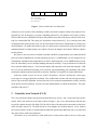
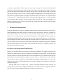
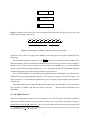
Design and Implementation of Efficient Message Scheduling for
Controller Area Network
Khawar M. Zuberi and Kang G. Shin
Real-Time Computing Laboratory
Department of Electrical Engineering and Computer Science
The University of Michigan
zuberi,kgshin @eecs.umich.edu
Abstract
The Controller Area Network (CAN) is being widely used in real-time control applications such
as automobiles, aircraft, and automated factories. In this paper we present the mixed traffic scheduler (MTS) for CAN, which provides higher schedulability than fixed-priority schemes like deadlinemonotonic (DM) while incurring less overhead than dynamic earliest-deadline (ED) scheduling. We
also describe how MTS can be implemented on existing CAN network adapters such as Motorola’s
TouCAN. In previous work [1, 2] we had shown MTS to be far superior to DM in schedulability performance. In this paper, we present implementation overhead measurements showing that processing
needed to support MTS consumes only about 5–6% of CPU time. Considering it’s schedulability advantage, this makes MTS ideal for use in control applications.
Key Words: Distributed real-time systems, Controller Area Network (CAN), message scheduling, network
scheduling implementation, priority inversion.
1
Introduction
Distributed real-time systems are being used increasingly in control applications such as in automobiles,
aircraft, robotics, and process control. These systems consist of multiple computational nodes, sensors, and
actuators interconnected by a LAN [3]. Of the multiple LAN protocols available for such use (including
MAP [4], TTP [5], etc.), the Controller Area Network (CAN) [6] has gained wide-spread acceptance in the
industry [7].
Control networks must carry both periodic and sporadic real-time messages, as well as non-real-time
messages. All these messages must be properly scheduled on the network so that real-time messages meet
their deadlines while co-existing with non-real-time messages (we limit the scope of this paper to scheduling messages whose characteristics like deadline and period are known a priori). Previous work regarding
scheduling such messages on CAN includes [8, 9], but they focused on fixed-priority scheduling. Shin [10]
The work reported in this paper was supported in part by the NSF under Grants MIP-9203895 and DDM-9313222, and by the
ONR under Grant N00014-94-1-0229. Any opinions, findings, and conclusions or recommendations are those of the authors and
do not necessarily reflect the views of the funding agencies.
1
SOF
Identifier
Data Len
Data
CRC
Ack
EOF
SOF: Start of Frame
CRC: Cyclic Redundancy Code
EOF: End of Frame
Figure 1: Various fields in the CAN data frame.
considered earliest-deadline (ED) scheduling, but did not consider its high overhead which makes ED impractical for CAN. In this paper, we present a scheduling scheme for CAN called the mixed traffic scheduler
(MTS) which increases schedulable utilization and performs better than fixed-priority schemes while incurring less overhead than ED. This paper goes beyond the work presented in [1, 2] by removing some ideal
assumptions made in that previous work. We also describe how MTS can be implemented on existing CAN
network adapters. We address the problem of how to control priority inversion (low-priority message being
transmitted ahead of a higher-priority one) within CAN network adapters and evaluate different solutions
for this problem.
We measure various execution overheads associated with MTS by implementing it on a Motorola 68040
processor with the EMERALDS real-time operating system [11]. EMERALDS is an OS designed for use
in distributed, embedded control applications. For MTS’s implementation, we use EMERALDS to provide
basic OS functionality such as interrupt handling and context switching. Using an emulated CAN network
device (another 68040 acting as a CAN network adapter and connected to the main node through a VME
bus), we present detailed measurements of all execution, interrupt handling, task scheduling, and context
switching overheads associated with MTS to show the feasibility of using MTS for control applications.
In the next section we give an overview of the CAN protocol. Section 3 describes the various types
of messages in our target application workload. They include both real-time and non-real-time messages.
Section 4 gives the MTS algorithm. Section 5 discusses issues related to implementation of MTS, focusing
on the priority inversion problem. Section 6 presents implementation overhead measurements. The paper
concludes with Section 7.
2
Controller Area Network (CAN)
The CAN specification defines the physical and data link layers (layers 1 and 2 in the ISO/OSI reference
model). Each CAN frame has seven fields as shown in Figure 1, but we are concerned only with the data
length (DL) and the identifier (ID) fields. The DL field is 4 bits wide and specifies the number of data bytes
in the data field, from 0 to 8. The ID field can be of two lengths: the standard format is 11-bits, whereas
the extended format is 29-bits. It controls both bus arbitration and message addressing, but we are interested
only in the former which is described next.
CAN makes use of a wired-OR (or wired-AND) bus to connect all the nodes (in the rest of the paper
2
we assume a wired-OR bus). When a processor has to send a message it first calculates the message ID
which may be based on the priority of the message. The ID for each message must be unique. Processors
pass their messages and associated IDs to their bus interface chips. The chips wait till the bus is idle, then
write the ID on the bus, one bit at a time, starting with the most significant bit. After writing each bit, each
chip waits long enough for signals to propagate along the bus, then it reads the bus. If a chip had written
a 0 but reads a 1, it means that another node has a message with a higher priority. If so, this node drops
out of contention. In the end, there is only one winner and it can use the bus. This can be thought of as a
distributed comparison of the IDs of all the messages on different nodes and the message with the highest
ID is selected for transmission.
3
Workload Characteristics
In control applications, some devices exchange periodic messages (such as motors and drives used in industrial applications) while others are more event-driven (such as smart sensors). Moreover, operators may
need status information from various devices, thus generating messages which do not have timing constraints. So, we classify messages into three broad categories, (1) hard-deadline periodic messages, (2)
hard-deadline sporadic messages, and (3) non-real-time (best-effort) aperiodic messages. A periodic message has multiple invocations, each one period apart (note that whenever we use the term message stream to
refer to a periodic, we are referring to all invocations of that periodic). Sporadic messages have a minimum
interarrival time (MIT) between invocations, while non-real-time messages are completely aperiodic, but
they do not have deadline constraints.
Low-Speed vs. High-Speed Real-Time Messages
Messages in a real-time control system can have a wide range of deadlines. For example, messages from a
controller to a high-speed drive may have deadlines of few hundreds of microseconds. On the other hand,
messages from devices such as temperature sensors can have deadlines of a few seconds because the physical
property being measured (temperature) changes very slowly. Thus, we further classify real-time messages
into two classes: high-speed and low-speed, depending on the tightness of their deadlines. As will be clear
in Section 4, the reason for this classification has to do with the number of bits required to represent the
deadlines of messages.
Note that “high-speed” is a relative term — relative to the tightest deadline D0 in the workload. All
messages with the same order of magnitude deadlines as D0 (or within one order of magnitude difference
from D0 ) can be considered high-speed messages. All others will be low-speed.
3
4
The Mixed Traffic Scheduler
Fixed-priority deadline monotonic (DM) scheduling [12] can be used for CAN by setting each message’s
ID to its unique priority as in [8, 9]. However, in general, fixed-priority schemes give lower utilization than
other schemes such as non-preemptive earliest-deadline 1 (ED). This is why several reaserchers have used
ED for network scheduling [15–17]. This motivates us to use ED to schedule messages on CAN, meaning
that the message ID must contain the message deadline (actually, the logical inverse of the deadline for a
wired-OR bus). But as time progresses, absolute deadline values get larger and larger, and eventually they
will overflow the CAN ID. This problem can be solved by using some type of a wrap-around scheme (which
we present in Section 4.1) but even then, puting the deadline in the ID forces one to use the extended CAN
format with its 29-bit IDs. Compared to the standard CAN format with 11-bit IDs, this wastes 20–30%
bandwidth, negating any benefit obtained by going from fixed-priority to dynamic-priority scheduling. This
makes ED impractical for CAN.
In this section we present the MTS scheduler which combines ED and fixed-priority scheduling to
overcome the problems of ED.
4.1 Time Epochs
As already mentioned, using deadlines in the ID necessitates having some type of a wrap-around scheme.
We use a simple scheme which expresses message deadlines relative to a periodically increasing reference
Then, the deadline field for message i will be the logical inverse of d SOE d , where d is the
called the start of epoch (SOE). The time between two consecutive SOEs is called the length of epoch, .
i
i
t
i
absolute deadline of message i and t is the current time (it is assumed that all nodes have synchronized
clocks [18]).
4.2 MTS
The idea behind MTS is to use ED for high-speed messages and DM for low-speed ones. First, we give
high-speed messages priority over low-speed and non-real-time ones by setting the most significant bit to 1
in the ID for high-speed messages (Figure 2a). This protects high-speed messages from all other types of
traffic. If the uniqueness field is to be 5 bits [2] (allowing 32 high-speed messages), and the priority field
is 1 bit, then the remaining 5 bits are still not enough to encode the deadlines (relative to the latest SOE).
Our solution is to quantize time into regions and encode deadlines according to which region they fall in. To
distinguish messages whose deadlines fall in the same region, we use the DM-priority of a message as its
uniqueness code. This makes MTS a hierarchical scheduler. At the top level is ED: if the deadlines of two
messages can be distinguished after quantization, then the one with the earlier deadline has higher priority.
1 Non-preemptive
scheduling under release time constraints is NP-hard in the strong sense [13]. However, Zhao and Ramam-
ritham [14] showed that ED performs better than other simple heuristics.
4
1
deadline
DM priority
(a)
0 1
DM priority
(b)
0 0
fixed priority
(c)
Figure 2: Structure of the ID for MTS. Parts (a) through (c) show the IDs for high-speed, low-speed, and
non-real-time messages, respectively.
000
001
010
011
100
SOE
101
end of epoch
110
111
Figure 3: Quantization of deadlines (relative to start of epoch) for m
3.
At the lower level is DM: if messages have deadlines in the same region, they will be scheduled by their
DM priority.
We can calculate length of a region (lr ) as lr
Dmax
2m
where Dmax is the longest relative deadline of any
high-speed message and m is the width of the deadline field (5 bits in this case). This is clear from Figure 3
(shown for m
3). The worst-case situation occurs if a message with deadline Dmax is released just before
the end of epoch so that its absolute deadline lies
Dmax beyond the current SOE. The deadline field must
encode this time span using m bits leading to the above expression for lr .
We use DM scheduling for low-speed messages and fixed-priority scheduling for non-real-time ones,
with the latter being assigned priorities arbitrarily. The IDs for these messages are shown in Figures 2 (b)
and (c) respectively. The second-most significant bit gives low-speed messages higher priority than nonreal-time ones.
This scheme allows up to 32 different high-speed messages (periodic or sporadic), 512 low-speed messages (periodic or sporadic), and 480 non-real-time messages2 — which should be sufficient for most
applications.
4.3 ID Update Protocol
The IDs of all high-speed messages have to be updated at every SOE. Note that if ID updates on different
nodes do not coincide (almost) exactly, priority inversion can occur if the ID of a low-priority message is
updated before that of a high-priority one. Then, for a small window of time, the low-priority message will
2 CAN disallows consecutive zeros in the six most significant bits of the ID. This means that 32 codes for non-real-time messages
are illegal which leaves 512
32
480 legal codes.
5
have a higher priority ID than the high-priority message. To avoid this problem, we must use an agreement
protocol to trigger the ID update on all nodes. The CAN clock synchronization algorithm [18] synchronizes
clocks to within 20µs. A simple agreement protocol can be that one node is designated to broadcast a
message on the CAN bus. This message will be received by all nodes at the same time (because of the
nature of the CAN bus) and upon receiving this special message, all nodes will update the IDs of their
local messages. But this protocol has two disadvantages. First of all, too much CAN bandwidth is wasted
transmitting the extra message every
seconds. Moreover, a separate protocol must be run to elect a new
leader in case the old leader fails. Instead, we use the following protocol which is not only robust but also
consumes less bandwidth. Each node has a periodic timer which fires every
seconds at which time the
node takes the following actions:
1. Set a flag to inform the CAN device driver that the ID update protocol has begun.
2. Configure the CAN network adapter to receive all messages (i.e., enter promiscuous mode by adjusting the receive filter).
3. Increment the data length (DL) field of the highest-priority ready message on that node.
The first incremented-DL message to be sent on the CAN bus will serve as a signal to all nodes to update
the IDs of their messages. If the original DL of the message is less than 8, then incrementing the DL will
result in transmission of one extra data byte (device drivers on receiving nodes strip this extra byte before
forwarding the message to the application as described later). If the DL is already 8, CAN adapters allow
the 4-bit DL field to be set to 9 (or higher) but only 8 data bytes are transmitted.
Now, each node starts receiving all messages transmitted on the CAN bus. The device driver on each
node has a table listing the IDs of all message streams in the system along with their data lengths. As
messages arrive, the device driver compares their DL field to the values in this table until it finds a message
with an incremented DL field. All nodes receive this message at the same time and they all take the following
actions:
1. Restore the receive filter to re-enable message filtering in the NA.
2. If the local message whose DL field was incremented by the periodic timer has not been transmitted
yet, then decrement the DL field back to its original value.
3. Update message IDs to reflect the new SOE.
Each node receives the incremented-DL message at the same time, so the ID update on each node starts at
the same time. After the first incremented-DL message completes, the next-highest-priority message begins
transmission. As long as all nodes complete their ID updates before this message completes (a window of
at least 55µs since this message contains at least one data byte), all messages will have updated IDs by the
time the next bus arbitration round begins and no priority inversion will occur. In case one or more nodes are
6
slow and cannot complete the ID update within this window of time, all nodes can be configured to do the
update while the nth message after the first incremented-DL message is in transmission, where n is a small
number large enough to allow the slowest node to calculate all new IDs and then just write these to the NA
while the nth message is in transmission.
This protocol incurs a network overhead of 16 bits every
seconds (compared to 47 bits per epoch
for the simple leader-based agreement protocol). Reception of the first incremented-DL message causes
the device drivers to set the DL fields of their local messages back to their original values, but before this
can complete, the next transmission (also with an incremented DL field) has already started. These two
messages have 8 extra data bits each (worst-case) which leads to the 16-bit overhead. On the CPU side, the
periodic process incurs some overhead. Moreover, while the network adapter’s filter is disabled, the device
drivers must process two messages which may or may not be meant for that node. The device drivers must
perform filtering in software and discard messages not meant for their node. Measurements of these various
CPU overheads are in Section 6.
5
Implementation
In this section, we present schemes to implement MTS on Motorola’s TouCAN module [19] which features
16 message buffers and internal arbitration between transmission buffers based on message ID. As such,
TouCAN is representative of modern CAN NAs.
In the following, we present a brief description of TouCAN, the problems faced when implementing
real-time scheduling on CAN, and our solution to these problems for MTS.
5.1 Motorola TouCAN
TouCAN is a module developed by Motorola for on-chip inclusion in various microcontrollers. TouCAN
lies on the same chip as the CPU and is interconnected to the CPU (and other on-chip modules) through
Motorola’s intermodule bus. Motorola is currently marketing the MC68376 [19] microcontroller which
incorporates TouCAN with a CPU32 core.
TouCAN has 16 message buffers. Each buffer can be configured to either transmit or receive messages.
When more than one buffers have valid messages waiting for transmission, TouCAN picks the buffer with
the highest-priority ID and contends for the bus with this ID. In this respect TouCAN differs from older
CAN network adapters such as the Intel 82527 [20] which arbitrate between buffers using a fixed-priority,
daisy-chain scheme which forces the host CPU to sort messages according to priority before placing them in
the network adapter buffers. This was one of the main reason we picked TouCAN for implementing MTS.
At this time, TouCAN is available only with the MC68376 microcontroller. To implement MTS within
EMERALDS on TouCAN, we would first have to port EMERALDS to the MC68376 microcontroller. To
avoid this, we instead used device emulation [21] under which a general-purpose microcontroller is made
to emulate a network adapter. This emulator interfaces to the host CPU through an I/O bus. The emulator
7
presents the host CPU the same interface that the actual network adapter would. The emulator receives
commands from the host CPU, performs the corresponding actions, and produces the same results that the
actual network adapter would, thus providing accurate measurements of various overheads such as interrupt
handling and message queuing on host CPU. We use a 68040 board to emulate the TouCAN module and
connect it to the host CPU (another 68040) through a VME bus.
5.2 MTS on CAN
In implementing MTS on CAN, our goal is to minimize the average overhead suffered by the host node for
transmitting a message. This overhead has the following components:
1. Queuing/buffering messages in software if network adapter buffers are unavailable.
2. Transferring messages to network adapter.
3. Handling interrupts related to message transmission.
In CAN, priority inversion can be unbounded. If the adapter buffers contain low-priority messages, these
messages will not be sent as long as there are higher-priority messages anywhere else in the network. Consequently, a high-priority message can stay blocked in software for an indeterminate period of time, causing
it to miss its deadline. Because of this priority inversion problem, any network scheduling implementation
for CAN (regardless of which scheduling policy — DM or MTS — is being implemented) has to ensure that
adapter buffers always contain the highest-priority messages and only lower-priority messages are queued
in software.
Suppose B buffers are allocated for message transmission (usually B is about two-thirds of the total
number of buffers; see Section 6). If the total number of outgoing message streams is B or less, then MTS’s
implementation is straight-forward: assign one buffer to each stream. Whenever the CAN device driver
receives a message for transmission, it simply copies that message to the buffer reserved for that stream.
In this case, no buffering is needed within the device driver which also means that there is no need for the
CAN adapter to generate any interrupts upon completion of message transmission 3, and this leads to the
lowest-possible host CPU overhead.
When number of message streams exceeds B, some messages have to be buffered in software. To
reduce host CPU overhead, we want to buffer the fewest possible messages while avoiding priority inversion.
Just as MTS treats low-speed and high-speed messages differently for scheduling purposes, we treat these
messages differently for implementation purposes as well. Our goal is to keep the overhead for frequent
messages (those belonging to high-speed periodic streams) as low as possible to get a low average permessage overhead. In our implementation, if the number of periodic high-speed message streams NH p is
3 The
CAN adapter must be programmed to generate interrupts if messages are queued in software waiting for adapter buffers to
become available, which is not the case here.
8
less than B, then we reserve NH p buffers for high-speed periodic streams and treat them the same as before
(no buffering in software).
The remaining L
B
NH p buffers are used for high-speed sporadic, low-speed, and non-real-time
messages. As these messages arrive at the device driver for transmission, they are inserted into a prioritysorted queue. To avoid priority inversion, the device driver must ensure that the L buffers always contain
the L messages at the head of the queue. So, if a newly-arrived message has priority higher than the lowestpriority message in the buffer, it “preempts” that message by overwriting it. This preemption increases CPU
overhead but is necessary to avoid priority inversion. The preempted message stays in the device driver
queue and is eventually transmitted according to its priority.
Among these L buffers, the buffer containing the I
1th lowest priority message is configured to trigger
an interrupt upon message transmission (I is defined later). This interrupt is used to refill the buffers with
queued messages. I must be large enough to ensure that the bus does not become idle while the interrupt is
handled and buffers are refilled. Usually an I of 1 or 2 is enough (which can keep the bus busy for 47–94 µs
minimum). Note that this puts a restriction on L that it must be greater than I. Making L less than or equal
to I can lead to the CAN bus becoming idle while the ISR executes, but makes more buffers available for
high-speed periodic messages. This can be useful if low-speed messages make up only a small portion of
the workload and high-speed sporadic messages are either non-existent or very few.
If NH p
B then we must queue even high-speed periodic messages in software. Then we have a single
priority-sorted queue for all outgoing messages and all B buffers are filled from this queue.
Overheads
For streams with dedicated buffers, the CPU overhead is just the calculation of the message ID and transferring the message data and ID to the network adapter. Note that message data can be copied directly from
user space to the network adapter to keep overhead to a minimum.
For messages which are queued in software, there is an extra overhead of inserting the message in the
queue (including copying the 8 or fewer bytes of message data from user space to device driver space before
inserting in the queue), plus the overhead for handling interrupts generated upon message transmission.
This interrupt overhead is incurred once every Q
I message transmissions, where Q is the number of
buffers being filled from the queue (Q can be B or L depending on whether high-speed periodic messages
are buffered or not). Also, each message will potentially have to preempt one other message. The preempted
message had already been copied to the network adapter once and now it will have to be copied again, so
the preemption overhead is equivalent to the overhead for transferring the message to the network adapter.
Table 1 summarizes the overheads for various types of messages. Measurements of these overheads are in
Section 6.
Note that DM scheduling also incurs similar overheads. The only difference is that the ID of message streams under DM is fixed, so a new ID does not have to be calculated each time. Other than that,
implementing DM on TouCAN is no different than implementing MTS.
9
Message type
Overhead
Not queued
Calculate ID + copy to NA
............
...........................................................
Queued
Calculate ID + insert in priority queue + copy to NA + preempt +
interrupt/(Q
I)
Table 1: Summary of overheads for MTS’s implementation on TouCAN.
6
Results
Schedulability of MTS as compared to DM and ED has been evaluated and published in [1, 2]. Here, we
present a measurement of various MTS implementation overheads and their impact on MTS schedulability.
The overhead measurements for implementation of MTS on a 25MHz Motorola 68040 (no cache) with
the EMERALDS RTOS are in Table 2. From this data, we see that high-speed messages with dedicated
network adapter buffers incur an overhead of
ID calculation + transfer to NA + misc
16 8µs/msg.
Operation
Overhead (µs)
Calculate ID (high-speed messages)
3.0
Insert in priority queue (including copying to device driver memory)
6.3 + 1.55lQ
Transfer message to NA (8 data bytes)
7.8
Preempt message
7.8
Interrupt handling and dequeuing of transmitted messages
42.4
Miscellaneous (parameter passing, etc.)
6.0
Table 2: CPU overheads for various operations involved in implementing MTS.
If high-speed periodic messages are queued, then average per-message overhead depends on the number
of buffers used for transmission (Q). TouCAN has 16 buffers. Of these, 5–6 are usually used for message
reception and their IDs are configured to receive the various message streams needed by the node. This
leaves about 10 buffers for message transmission. Then, under worst-case scenario, message transmission
incurs an average overhead (assuming I
2):
ID calculation + queuing + preempt + transfer to NA +
interrupt
+ misc.
Q I
36 2 1 55l
Q
µs/msg,
where the worst-case lQ is the total number of message streams using that queue. Low-speed and non-
1 55l
real-time messages have fixed IDs, so they incur an overhead of 33 2
high-speed messages share the same queue.
10
Q
µs/msg if all low-speed and
If high-speed messages are using dedicated buffers, then Q
suming only 3 buffers are available and I
1 55l
of 70 3
Q
I is smaller for low-speed messages. As-
2, then low-speed and non-real-time messages incur overheads
1 55l
µs/msg while high-speed sporadic messages have overheads of 73 3
Q
µs/msg.
From these numbers we see that if a certain node has 7 high-speed periodic streams, 1 high-speed
sporadic stream, 10 streams of low-speed and non-real-time messages, and if the high-speed periodic mes-
sages make up 90% of the outgoing traffic while Q I
1 for high-speed sporadic/low-speed/non-real-time
70 3 1 55 11! 0 1 messages, then average per-message overhead comes to 16 8 0 9
23 9µ/msg.
Overhead is significantly higher if the number of high-speed periodic streams is large enough that high-speed
messages have to be queued. In that case, per-message overhead can be twice as much as the overhead when
high-speed periodic streams have dedicated buffers. Fortunately, real-time control applications do not have
more than 10–15 tasks per node (the well-known avionics task workload [22, 23] — which is accepted as
typifying real-time control applications — is an example). Not all tasks send inter-node messages and those
that do typically do not send more than 1–2 messages per task. This indicates that for most applications, dedicated buffers should be available for high-speed message streams, resulting in a low per-message overhead
in the 20–25µs range.
We used a simple linked list to sort messages in the priority queue. This works well for a small number
of messages (5–10) that typically need to be in the queue. For larger number of messages, a sorted heap will
give lower overhead.
Note that these overheads are applicable to DM as well. Only difference is that under DM, the ID does
not have to be calculated, so per-message overhead will be 3µs less than for MTS.
ID Re-adjustment at End of Epoch
Table 3 lists the CPU overheads incurred during the ID update protocol. Overhead for the periodic task
includes all context switching and CPU scheduling overheads. One context switch occurs when the task
wakes up and another when the task blocks. Both of these are included in the overhead measurements.
Operation
Overhead (µs)
Periodic task
68.0
Device driver interrupt (message arrival)
40.4
Read message from NA (8 data bytes)
7.8
Software filtering and DL lookup
3.0
ID update
2.8 per message
Table 3: CPU overheads for various operations involved in updating message IDs.
During each ID update, the device driver receives two messages (each incurring an overhead of 40 4
3 0 78
51 2µs including all context switching overheads). After receiving the first message, IDs of
high-speed messages are updated. Assuming IDs of 5 messages need to be updated, the total overhead per
11
epoch becomes 184 4µs. If
increase .
"
2ms, the ID update takes up about 9% of CPU time. This motivates us to
Increasing increases the level of quantization of deadlines which results in reduced schedulability for
high-speed messages. But on the other hand, the network overhead associated with ID updates (16 bits
per epoch) decreases, leading to increased schedulability. For
"
2ms, 16 extra bits per epoch consume
only 0 8% of the network bandwidth for a 1Mb/s bus, but their impact on network schedulability (due to
their blocking effect) is much higher. Our measurements showed that with this extra overhead, about 2–3
percentage points fewer workloads are feasible under MTS (for the same workload utilization) than without
this overhead. As such, increasing can result in a sizeable improvement in schedulability due to reduced
ID update overhead which can offset the loss in schedulability due to coarser quantization.
Figure 4 shows the effect of increasing
on schedulability. For each data point, we generate 1000
workloads and measure the percentage found feasible under MTS using the schedulability conditions in [2].
Each workload has with 8–15 high-speed periodic streams, 2 or 6 high-speed sporadic streams, 25 low-speed
periodic streams, and 4 low-speed sporadic streams. Deadlines of high-speed messages are set randomly
in the 0.5–2ms range while those for low-speed messages are set randomly between 2–100ms. Periods of
periodic messages are calculated by adding a small random value to the deadline, while MIT of sporadic
streams is set to 2s (for both low-speed and high-speed sporadic streams). Different data points are obtained
by varying the number of high-speed periodic streams from 8 to 15 which leads to a variation in workload
utilization roughly in the 50–100% range. All results include the overhead resulting from 16 extra bits per
epoch for ID updates.
This Figure shows that when is doubled from 2ms to 4ms, network schedulability is actually improved
slightly when two high-speed sporadic streams are in the workload. But when six sporadic streams are used,
loss in schedulability from coarser quantization is more than the gain from reduced ID update overhead,
so that 1–2 percentage points fewer workloads are feasible. These results show that for light-to-moderate
high-speed sporadic loads, increasing
high-speed sporadic loads,
#
to 4ms continues to give good performance, and even for heavy
4ms results in only a slight degradation in performance.
If is increased to 3ms, then the ID update CPU overhead reduces to about 6% of CPU time, whereas
for
7
$
4ms, it becomes 4.6% of CPU time.
Conclusion
The CAN standard message frame format has an 11-bit ID field. If fixed-priority scheduling (such as DM)
is used for CAN, some of these bits go unused. The idea behind MTS is to use these extra bits to enhance
network schedulability. MTS places a quantized form of the message deadline in these extra bits while
using the DM-priority of messages in the remaining bits. This enhances schedulability of the most frequent
messages in the system (high-speed messages) so that MTS is able to feasibly schedule more workloads
than DM.
12
Percent feasible workloads
100.0
'
80.0
60.0
((
40.0
20.0
%
0.0
50.0
%
((
Sporadics=2, l=2ms
Sporadics=2, l=4ms
Sporadics=6, l=2ms
Sporadics=6, l=4ms
60.0
% & %
70.0
80.0
Utilization (%)
%
90.0
%
100.0
Figure 4: Impact of changing on MTS schedulability.
Since message IDs are based on deadlines, they must be periodically updated. We presented a protocol
to perform this update without any priority inversion. This protocol consumes about 5–6% of CPU time,
but considering the large improvements in network schedulability that MTS displays over DM, this extra
overhead is justified.
We also presented a scheme to implement MTS on the TouCAN network adapter which is representative
of modern CAN network adapters. The biggest challenge in implementing CAN scheduling (be it MTS
or DM) is controlling priority inversion within the network adapter. We showed that because of CAN’s
characteristics (short message size), preemption of a message in the adapter by a newly-arrived, higherpriority outgoing message is an effective method for avoiding priority inversion.
A future avenue of research can be to study message reception issues for CAN to try to reduce the
average per-message reception overhead. Unlike message transmission, message reception does not depend
on which network scheduling policy (DM or MTS) is used. Message reception overheads can be reduced
by optimizing interrupt handling, using polling (instead of interrupts) to detect message arrival, or using a
combination of interrupts and polling.
References
[1] K. M. Zuberi and K. G. Shin, “Non-preemptive scheduling of messages on Controller Area Network
for real-time control applications,” in Proc. Real-Time Technology and Applications Symposium, pp.
240–249, May 1995.
[2] K. M. Zuberi and K. G. Shin, “Scheduling messages on Controller Area Network for real-time CIM
applications,” IEEE Trans. Robotics and Automation, vol. 13, no. 2, pp. 310–314, April 1997.
[3] R. S. Raji, “Smart networks for control,” IEEE Spectrum, vol. 31, no. 6, pp. 49–55, June 1994.
[4] Manufacturing Automation Protocol (MAP) 3.0 Implementation Release, MAP/TOP Users Group,
1987.
13
[5] H. Kopetz and G. Grunsteidl, “TTP – a protocol for fault-tolerant real-time systems,” IEEE Computer,
vol. 27, no. 1, pp. 14–23, January 1994.
[6] Road vehicles — Interchange of digital information — Controller area network (CAN) for high-speed
communication, ISO 11898, 1993.
[7] H. Zeltwanger, “An inside look at the fundamentals of CAN,” Control Engineering, vol. 42, no. 1, pp.
81–87, January 1995.
[8] K. W. Tindell, H. Hansson, and A. J. Wellings, “Analyzing real-time communications: Controller Area
Network (CAN),” in Proc. Real-Time Systems Symposium, pp. 259–263, December 1994.
[9] K. Tindell, A. Burns, and A. J. Wellings, “Calculating Controller Area Network (CAN) message response times,” Control Engineering Practice, vol. 3, no. 8, pp. 1163–1169, 1995.
[10] K. G. Shin, “Real-time communications in a computer-controlled workcell,” IEEE Trans. Robotics and
Automation, vol. 7, no. 1, pp. 105–113, February 1991.
[11] K. M. Zuberi and K. G. Shin, “EMERALDS: A microkernel for embedded real-time systems,” in Proc.
Real-Time Technology and Applications Symposium, pp. 241–249, June 1996.
[12] J. Y.-T. Leung and J. Whitehead, “On the complexity of fixed-priority scheduling of periodic, real-time
tasks,” Performance Evaluation, vol. 2, no. 4, pp. 237–250, December 1982.
[13] K. Jeffay, D. F. Stanat, and C. U. Martel, “On non-preemptive scheduling of periodic and sporadic
tasks,” in Proc. Real-Time Systems Symposium, pp. 129–139, 1991.
[14] W. Zhao and K. Ramamritham, “Simple and integrated heuristic algorithms for scheduling tasks with
time and resource constraints,” Jounal of Systems and Software, vol. 7, pp. 195–205, 1987.
[15] D. Ferrari and D. Verma, “A scheme for real-time channel establishment in wide-area networks,” IEEE
Journal on Selected Areas in Communications, vol. 8, no. 3, pp. 368–379, April 1990.
[16] D. D. Kandlur, K. G. Shin, and D. Ferrari, “Real-time communication in multi-hop networks,” IEEE
Trans. on Parallel and Distributed Systems, vol. 5, no. 10, pp. 1044–1056, October 1994.
[17] Q. Zheng and K. G. Shin, “On the ability of establishing real-time channels in point-to-point packetswitched networks,” IEEE Trans. Communications, pp. 1096–1105, February/March/April 1994.
[18] M. Gergeleit and H. Streich, “Implementing a distributed high-resolution real-time clock using the
CAN-bus,” in 1st International CAN Conference, September 1994.
[19] MC68336/376 User’s Manual, Motorola Inc., 1996.
[20] 82527 Serial Communications Controller Architectural Overview, Intel Corporation, 1993.
[21] A. Indiresan, A. Mehra, , and K. G. Shin, “The END: An emulated network device for evaluating
adapter design,” in Proc. 3rd Intl. Workshop on Performability Modeling of Computer and Communication Systems, 1996.
[22] C. D. Locke, D. Vogel, and T. Mesler, “Building a predictable avionics plarform in Ada: A case study,”
in Proc. Real-Time Systems Symposium, pp. 181–189, 1991.
[23] C. D. Locke, D. Vogel, L. Lucas, and J. Goodenough, “Generic avionics software specification,” Technical Report CMU/SEI-90-TR-8, Carnegie Mellon University, 1990.
14


![1] n T169](http://vs1.manualzilla.com/store/data/005696581_1-b5b272b0c99ea5fca956b563015d9b67-150x150.png)