1
US007154603B2
(12)
(54)
(75)
United States Patent
(10) Patent N0.:
Banks
(45) Date of Patent:
Dec. 26, 2006
INTERCHANGEABLE TIP-OPEN CELL
6,369,894 B1
FLUOROMETER
6,490,030 B1*
12/2002
6,670,617 B1
12/2003 Banks
6,685,840 B1
2/2004 Hatch
Inventor:
Rodney H. Banks, Aurora, IL (US)
(73)
Assignee: Nalco Company, Naperville, IL (US)
(*)
Notice:
2002/0054288 A1
.
A
1 N
pp .
4/2002 Rasimas et al.
Gill et al. ................... .. 356/71
5/2002 K'
t l.
1m 6 a
Subject to any disclaimer, the term of this
$1518 i1S5i’E{Sn§ed0€ adjusted under 35
(21)
US 7,154,603 B2
.
.
y
11/493 446
o.:
(22) Filed:
FOREIGN PATENT DOCUMENTS
ays.
W0
W0 03/060461 A2
7/2003
,
Jul. 26, 2006
(65)
OTHER PUBLICATIONS
Prior Publication Data
“SCUFA Submersible Fluorometer Performance Testing”, WWW.
Us 2006/0262309 A1
NOV' 23’ 2006
turnerdesigns.com/t2/esci/si0039., 11 pages, Dec. 1, 2003.
Related US. Application Data
(Continued)
<6” izn‘a‘suaaaoisapiizi‘ra4082/5336“,
"
’
'
(51) Int Cl
G01N 21/64
"
’
0“
74A HorneyAg
,
@112, 0r F'zrmi P eter AD'M'Th
.
1 att1a;
omas
M. Breininger
(2006.01)
(52)
US. Cl. .................... .. 356/417; 250/461.1; 356/73
(58)
Field of Classi?cation Search .............. .. 356/317,
356618’ 417’ 73; 250/458'1’ 45922674661112’
S
1,
_
?l f
ee app lcanon
(56)
L- Evans
'
1
h h,
e or Comp ete Seam
'
lstory'
References Cited
(
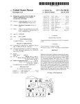
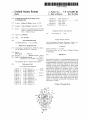
57
)
ABSTRACT
Described and claimed is an interchangeable tip-open cell
?uorometer comprising a housing and a ?uorometric probe
tip interchangeably connected to the housing, the probe tip
including a probe tip housing de?ning an open cell and
enclosing a probe optical arrangement, the probe optical
US. PATENT DOCUMENTS
2,663,801 A *
4,084,905 A *
12/1953
4/1978
4,301,372 A
11/1981 Giering et al.
4,577,110 A *
4,783,314 A
4,804,850 A *
4,992,380
5,994,707
6,060,318
6,255,118
6,280,635
6,329,165
A
A
A
B1
B1
B1
3/1986
Slavin et a1. ............. .. 250/365
Schreiber et a1. ......... .. 356/317
MacBride et a1. ..... .. 250/461.2
11/1988 Hoots et a1.
2/1989 Norrish et a1. ......... .. 250/459.1
2/1991 Moriarty et a1.
11/1999 Mendoza et al.
5/2000 Moeggenborg et al.
7/2001 Alfano et a1.
arrangement including an excitation source and a ?uores
cence detector Wherein the excitation source is aimed
directly into the ?uorescence detector such that a sample can
be ?uorometrically detected. Also claimed is a method of
using this interchangeable tip-open cell ?uorometer for
detecting ?uorescent signals emitted by one or more ?uo
rophores from samples from a natural or industrial Water
system. The ?uorometer, When coupled With a controller, is
capable of monitoring and optionally controlling an indus
trial process or system.
8/2001 Moriarty et a1.
12/2001 Chattoraj et a1.
2 Claims, 5 Drawing Sheets
1] n T169
US 7,154,603 B2
Page 2
OTHER PUBLICATIONS
J. Bloch, B. Johnson, N. NeWbury, J. Germaine, H. Hemond, J.
“SCUFA Submersible Fluorometer Performance Testing”, WWW.
?uorescence sensing of soil contamination”, Society for Applied
Spectroscopy, pp. 1299-1304, 1998. (Abstract only).
T Vo-Dinh., “Development of a DNA biochip: principle and appli
Sin?eld, “Field test of a novel microlaser-based probe for in situ
turnerdesigns.com/t2/esci/si0039, 9 pages, Jun. 14, 2004.
SCUFA User’s Manual, Turner Designs, 47 pages, Apr. 15, 2002.
K.-H. MittenZWey, G. Sinn, R. Hiersigk, M. Krause, P LenZ, L.
Pfeil, J. Rauchfuss, G. Streich, “A portable absorption-?uorometer
for detection of organic substances in ?uids”, Fresenius’ Journal of
Analytical Chemistry, p. 355, 1996. (Abstract only).
Robert F. Chen, “A laser-based ?ber-optic ?uorometer for in situ
seaWater measurements”, Ocean Science and Technology, pp. 189
209, 2000. (Abstract only).
cations”, Sensors and Actuators B: Chemical Ysensors Actuators B:
Chem., vol. B51, pp. 52-59. (Abstract only).
Maofan Qing, “The Design of a novel ?eld portable ?uorescence
spectrophotometer”, Current Developments in Optical Design and
Optical Engineering 111, pp. 140-145, 2000. (Abstract only).
* cited by examiner
U.S. Patent
Dec. 26, 2006
169
Sheet 1 0f 5
US 7,154,603 B2
U.S. Patent
Dec. 26, 2006
Sheet 2 0f 5
Ref-Detector
80
US 7,154,603 B2
169
169f - \,
62
UV
LED
60
/
say/gig [J
64”’
0 70
i- -- A/BB
74/
:::
-\_’
r\--- 72 74
i
"\_/76
FL Detector
66
U.S. Patent
Dec. 26, 2006
Sheet 3 0f 5
FIG. 3
Ref Detector
107
4 ~---,
FL Detector
US 7,154,603 B2
U.S. Patent
Dec. 26, 2006
Sheet 4 0f 5
FIG. 4
US 7,154,603 B2
U.S. Patent
Dec. 26, 2006
US 7,154,603 B2
Sheet 5 0f 5
P
om?
.QEm
@@
m
MW1<
_8.E5m_w
M2
NDN2A?
6 25$032%
a;891
f.
E?
Q2 v2
\_
l
US 7,154,603 B2
1
2
INTERCHANGEABLE TIP-OPEN CELL
FLUOROMETER
example, Water from a natural or an industrial Water system
is placed and held in the optically appropriate cell. When
conducting on-line testing, the sample of Water can ?oW
through the optically appropriate cell. The light is absorbed
by a ?uorophore present in the Water sample, Which, in turn,
CROSS REFERENCE TO RELATED
APPLICATIONS
emits a ?uorescent light (hereinafter knoWn as a ?uorescent
This application is a continuation application of US.
patent application Ser. No. 10/769,631, Which Was ?led on
Jan. 30, 2004 now US. Pat. No. 7,095,500.
excitation light. The emission ?lter, Which is positioned
betWeen the emission detector and the optically appropriate
FIELD OF THE INVENTION
?uorophore (the ?uorescent signal of the ?uorophore) to
signal) having the same or a longer Wavelength than the
cell, is chosen so as to permit only the light emitted by the
pass through the ?lter to the emission detector.
The present invention relates generally to analytical
devices and methods for monitoring and/or controlling natu
The use of ?uorophores in industrial Water systems or in
hydrology in general is knoWn. The use of inert ?uorescent
tracers for determining the hydraulic losses in an industrial
Water system is knoWn. Furthermore, using ?uorescent
tracers for controlling additive or product dosage to a
recirculating or once-through cooling Water system is also
knoWn (see US. Pat. No. 4,783,314). In this method, a
ral or industrial processes or systems. More speci?cally, the
present invention relates to an interchangeable tip-open cell
?uorometer for detecting ?uorescence emitted by a sample
derived from a natural or an industrial process or system
such that the process or system can be monitored and,
optionally, controlled.
20
?uorescent tracer is combined With one or more additives in
a knoWn proportion of tracer to additive(s) and then the
mixture is added to the Water of a cooling system. A
BACKGROUND OF THE INVENTION
?uorometer is then used to detect the presence and concen
A ?uorometer is an analytical device that essentially
comprises a light source, a means of selecting the desired
excitation Wavelength range, a sample cell, a means of
25
selecting the desired emission Wavelength range, and a
detector. A spectro?uorometer is a speci?c type of ?uorom
eter Where the means for selecting the excitation and/or
emission Wavelength range is performed by a grating. A
tration of the ?uorescent tracer in the cooling Water and
therefore the presence and concentration of the amount of
additive.
There Will alWays be a continuing need for neW and
improved ?uorometers to be available for use in the chal
lenging area of monitoring and controlling industrial Water
30
processes.
grating acts to disperse a continuum of light into its com
ponents. Spectro?uorometers may be further subdivided into
scanning spectro?uorometers, those that use a mechanical
means to scan the Wavelength spectrum based on the posi
tion of the grating relative to the excitation source and/or
emission (this describes a standard laboratory model ?uo
SUMMARY OF THE INVENTION
The ?rst aspect of the instant claimed invention is an
35
a housing and a ?uorometric probe tip interchangeably
connected to the housing, the probe tip including a probe tip
housing de?ning an open cell and enclosing a probe optical
arrangement, the probe optical arrangement including an
rometer), or ?xed spectro?uorometers Where the grating is
?xed With respect to the emission. The emission (?uores
cence) is then directed to an array of detectors. The array of
detectors could be charge coupled devices, usually abbre
40
viated “CCD” or the array of detectors could be photo
diodes. The detectors are then calibrated in the appropriate
Wavelength units. A commercial device such as this is
available from Ocean Optics (available from Drysdale and
Associates, Inc., PO. Box 44055, Cincinnati, Ohio 45244
(513) 831-9625). This type of ?xed spectro?uorometer still
excitation source and a ?uorescence detector Wherein the
excitation source is aimed at the ?uorescence detector such
that a sample can be ?uorometrically detected.
The second aspect of the instant claimed invention is a
method of ?uorometrically detecting ?uorophores present in
45
a sample, the method comprising the steps of:
50
a) providing a ?uorometer, the ?uorometer comprising
a housing and a ?uorometric probe tip interchangeably
connected to the housing, the probe tip including a probe tip
housing de?ning an open cell and enclosing a probe optical
arrangement, the probe optical arrangement including an
requires the appropriate excitation Wavelength selection
device, Which could be a grating or ?lter.
The ?uorometers that are most suitable for use under ?eld
conditions are not grating spectro?uorometers, rather, they
interchangeable tip-open cell ?uorometer comprising:
a ?lter to exclude all but the selected Wavelength range. In
excitation source and a ?uorescence detector Wherein the
excitation source is aimed at the ?uorescence detector such
general, currently available and knoWn ?lter-based ?uorom
that a sample can be ?uorometrically detected;
are ?lter-based ?uorometers. A ?lter-based ?uorometer uses
eters have one channel With this channel containing an
optically appropriate cell.
55
b) providing one or more samples derived from a natural
or industrial process stream;
c) using the ?uorometer to detect the ?uorescent signals
of the ?uorophores in the samples; and
A light source and an optional excitation ?lter, are posi
tioned on one side of the optically appropriate cell, and an
emission detector and an emission ?lter are positioned on
d) operating a controller in such a Way that the ?uorescent
another side of the optically appropriate cell. A reference
detector may optionally be present. Because ?uorescence is
isotropic, in general, ?uorometers are con?gured to detect
signals detected by the ?uorometer are used by the controller
60
from Which the samples are taken.
any ?uorescent light emitted from the ?uorophore at a 900
angle from the light source in order to minimiZe collection
of any spurious excitation light.
The excitation ?lter permits light of the chosen excitation
Wavelength range to pass through the ?lter and into the cell.
When conducting off-line batch testing, a sample of, for
to monitor and/or control the natural or industrial process
BRIEF DESCRIPTION OF THE DRAWINGS
65
FIG. 1 is a cut aWay sectional vieW of an interchangeable
probe tip for a ?uorometer made in accordance With the
present invention.
US 7,154,603 B2
4
3
tion contemplates an arrangement With respect to the exci
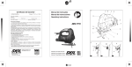
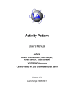
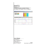
FIG. 2 is a cut away sectional vieW of another inter
changeable probe tip for a ?uorometer made in accordance
With the present invention.
tation source and the ?uorescence detector that can deviate
from a 180° arrangement as described beloW in greater
detail.
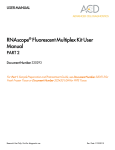
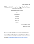
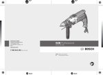
FIG. 3 is a cut aWay sectional vieW of yet another
The interchangeable tip-open cell ?uorometer of the
interchangeable probe tip for a ?uorometer made in accor
dance With the present invention.
present invention can provide a loW-cost alternative to
conventional ?uorometers. In an embodiment, the ?uorom
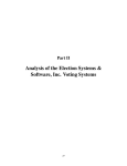
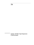
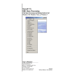
FIG. 4 is a cut aWay sectional vieW of still yet another
interchangeable probe tip for a ?uorometer made in accor
dance With the present invention.
FIG. 5 is a sectional vieW of an interchangeable probe tip
?uorometer made in accordance With the present invention.
eter of the present invention is provided in a ?ashlight-style
that can be hand-held and shaped in any suitable Way, such
as a cylindrical tube shape. In this regard, a measurement
can be taken by dipping the interchangeable tip of the
?uorometer of the present invention into a process Water
DETAILED DESCRIPTION OF THE
PRESENTLY PREFERRED EMBODIMENTS
sample, for example, cooling Water treated With treatment
chemicals and using ?uorometers for detecting ?uorophores,
pushing a button, and reading the product level, such as in
Throughout this patent application the folloWing Words
have the indicated meanings:
parts per million (ppm) on a display.
With this ?uorometer, the design emphasis is on minimal
A “?uorophore” is: a molecule that, upon absorption of a
photon of energy (hv) that results in an electron being
promoted from the molecular electronic ground state (S0) to
tors. The cylindrical tube-shape has many desirable func
cost for small accounts and ease of use for unskilled opera
20
a photon of energy “E” (hv) that is loWer in energy (though
longer in Wavelength) than Was absorbed. Note that this
relationship can be illustrated With the equation: Ewbsorp?on)
>E(?uorescence). This emission of energy results in the
communications to Palm computer or the like for doWn
25
connector, for controlling a chemical feed pump, data log
ging and/or for performing other suitable process monitoring
and/or control activities. For example, the ?uorometer of the
30
interchangeable probe tip. In general, the probe tip provides
a small, self-contained ?uorometer With built-in optics and
35
in the cooling Water system, or by the other system param
eters such as metallurgical composition, microbiological
activity, biocide concentration, heat changes or overall heat
content. To quantify What is meant by “not appreciably or
signi?cantly affected”, this statement means that an inert
?uorophore has no more than a 10% change in its ?uorescent
sources, temperature measurement and the like. The probe
40
ferent optics is necessary to account for changes in the
sampling environment, such as for measuring the ?uores
cence derived from different ?uorophores, tip damage and/
or the like. Upon replacing one interchangeable tip for
45
With minimal, or effectively no, added effort required from
the operator. This is a huge practical advantage of the instant
claimed invention, especially When compared to the effort
another interchangeable tip, the ?uorometer is ready-for-use
?uorescent light is emitted equally in all directions, creating,
required to set up and use two different ?uorometers.
in effect, a sphere in 3 dimensions.
“nm” means nanometers; Which are 10'9 meters.
In this regard, the probe tip contains virtually all of the
50
The present invention provides an interchangeable tip
open cell ?uorometer. This interchangeable tip-open cell
55
in a measuring cell associated With the ?uorometer such as
a measuring cell in an open or ?oW cell con?guration. In
60
approximate 180° arrangement. This effectively provides a
sleek and simple design that can be effectively used to
based on a ?uorometric measurement from a sample derived
from same. It should be appreciated that the present inven
The probe tip also optionally can include a thermistor. It
is preferred that the probe tip include a thermistor to measure
sample temperature for correction of ?uorescence intensity.
By choosing di?ferent thermistor resistances based on, for
example a temperature of 25° C., the probe tips are effec
tively self-identifying Without added cost or complexity. In
source is aimed at the ?uorescence detector, such as directly
at the detector in a 180° arrangement or substantially
detect, monitor and/or control industrial or natural streams
Further, noise interferences can be minimized by having the
electronics inside of the probe tip. The excitation source,
such as a light emitting diode (LED) source, can be con?g
ured to have its oWn series resistor so that the main unit does
not have to regulate LED current.
general, the probe tip optical arrangement includes an exci
tation source and a ?uorescence detector such that excitation
electronics and optics to perform the ?uorescence measure
ments. For example, proper gain can be built into the
electronic con?guration associated With the probe tip, thus
relieving the main unit from having to adjust gain settings.
?uorometer includes one or more probe tips that can be
interchangeably used With respect to the same ?uorometer.
At least one of the probe tips includes an optical arrange
ment that alloWs for the ?uorometric detection of a sample
circuitry, such as for type identi?cation, detectors, light
tip is constructed such that it is readily pluggable into the
?uorometer housing. This makes it easily replaceable With
another probe tip Whenever a different probe tip With dif
signal, under conditions normally encountered in cooling
Water systems. Conditions normally encountered in cooling
Water systems are knoWn to people of ordinary skill in the
art of cooling Water systems.
“Isotropic” refers to the fact that if a moiety is considered
a point source, and excitation light is directed at the moiety,
present invention can be adapted to alert the user When
cleaning of the tip is required.
An important aspect of the present invention is the
lengths of from about 200 nm to about 1200 nm and emitting
it at a longer Wavelength than the excitation light.
“Inert” refers to the fact that an inert ?uorophore is not
appreciably or signi?cantly affected by any other chemistry
loading of stored data, a unique, self-identifying ?uorometer
probe tip and the like. The ?uorometer of the present
invention can be made With a process control output and
molecular electronic state being returned to the ground state
(S0). The overall process results in emission of ?uorescent
photons in an isotropic distribution. The ?uorophores
capable of being detected by the instant claimed ?uorometer
must be capable of absorbing excitation light in the Wave
tional features including battery operation, numerical read
out, tWo-point calibration, compensation for sample
temperature, turbidity, and fouling of the optical surfaces,
an electronic excited state (S 1 or S2 or S3) and subsequently
relaxing to the loWest vibronic state of excited state S1, emits
65
other Words, each probe tip can include a thermistor With a
resistance that is speci?c to the respective probe tip. Once
the probe tip is plugged into the ?uorometer housing and the
US 7,154,603 B2
5
6
thermistor resistance is made known, the speci?c optical and
electronic arrangement With respect to the probe tip can be
surface of the excitation light ?lter and the surface of the
emission light ?lter. The sample is in direct contact With the
?lters as previously discussed. This alloWs the excitation
identi?ed, thus allowing the interchangeable tip-open cell
?uorometer to be ready-for-use.
light to project into the sample Within the measuring cell
As previously discussed, the probe tip has an optical
Whereupon ?uorescence is produced due to the presence of
arrangement that provides a linear and slim pro?le for the
?uorometer. In this regard, the excitation source of the probe
tip is aimed at the ?uorescence detector. For example, the
excitation source and/or the light that emits therefrom and
one or more ?uorophores in the sample. The emitted ?uo
rescence then passes through an additional ?lter and is
directed to a ?uorescence detector for detection purposes.
The additional ?lter also acts to effectively block the exci
the ?uorescence detector can be con?gured in a 180°
tation light from passing to the ?uorescence detector. This
alloWs the ?uorescence of the sample to be measured With
precision, sensitivity and accuracy despite the fact that the
excitation light is directed at the ?uorescence detector, such
arrangement or acceptable deviations thereof. This is differ
ent from conventional one-channel-sample ?uorometers
Where detection of the ?uorescent light emitted from the
?uorophore is at a 90° angle from the light source as
previously discussed. Based on these differences, the inter
as directly at the ?uorescence detector in a 180° optical
changeable tip-open cell ?uorometer of the present inven
arrangement. As previously discussed, this optical arrange
tion can provide a number of advantages over conventional
ment provides a number of advantages as compared to
?uorometers that use a conventional 90° optical arrange
one-channel-sample ?uorometers including, for example, a
sleek and simple design, selectable sensitivity, accurate
compensation for turbidity and WindoW fouling, and the like
ment.
20
as described beloW.
The ?uorometer of the present invention makes use of a
speci?c type of optical ?lters, such as a thin-?lm optical
?lter With the requisite optical, mechanical and chemical
properties necessary to enhance the ?uorescent detection
capabilities. The physical attributes of the ?lters can also
enhance the detection sensitivity as compared to quartz,
above. Regarding the description of the ?uorophores
capable of being detected by the instant claimed ?uorometer,
it is necessary to note that in order to be detectable by the
25
Wavelength. Preferably, the ?uorophores absorb light in the
unWanted light scattering such that the sensitivity and con
Wavelengths of from about 350 nm to about 800 nm. The
centration range can be reduced. In this regard, the measured
sample is in direct contact With the ?lters that de?ne the
measuring volume. Thus the use of the term “open cell” as
a descriptor of the fact that it is the ?lters themselves that
form the outer boundaries of the sample cell and there is no
30
other structure involved in the sample cell, except for the
outer Walls of the housing itself.
35
in the sample. In an embodiment, the ?uorescence detector
can measure an intensity of the ?uorescence that can be
equated to a concentration of the ?uorophore as generally
40
sample side and air interface on the internal side, perfor
levels of ?uorophores.
45
variety of different components fashioned in any suitable
50
detection purposes in any suitable Way, such as for grab
55
The excitation source can include any suitable type of light
source, such as a monochromatic light source, polychro
With respect to the ?uorescent measurement are effectively
eliminated, or at least greatly reduced. This effect can be
further enhanced if the pass bands of the ?lters are sharp and
the ?lters alloW the second light in a su?icient amount to
pass through both ?lters and at a different Wavelength than
the light emitted from the excitation source. In this Way, the
second light source can be used to correct for fouling,
turbidity and/or other like effects that can adversely impact
60
the detection capabilities of the ?uorometer as described in
greater detail beloW.
With respect to mechanical properties, the ?lter includes
source can include a LED source, a laser source and the like.
The LED source can emit light of varying Wavelengths, such
an exposed surface that is hard such that it can Withstand
as an IR LED, a UV LED, a blue LED and/or the like.
The excitation source generates a collimated beam of
con?guration de?ned by the probe tip housing and the
for the excitation light (i.e., UV LED) or the emitted
?uorescence. As mentioned above, the ?rst ?lter essentially
alloWs all of the excitation light to pass therethrough and
into the sample. Then, the emitted ?uorescence from the
sample can pass through the second ?lter all the While the
deep cut.
If a second light source is used, the optical properties of
sampling purposes, in-line detection, in-process detection
and/ or the like.
excitation light. The excitation light passes through a ?lter in
the probe tip and into a measuring cell With an open-cell
are required to have a high transmittance in pass band areas
the second ?lter and inevitably to the detector. Thus, this
ensures that the interference effects of the excitation light
interchangeable tip-open cell ?uorometer can be adapted for
matic light source and the like. For example, the excitation
the ?lter are provided and required as folloWs according to
an embodiment. With respect to optical properties, the ?lters
excitation light is effectively blocked from passing through
con?guration depending on the application. It can be con
?gured as a stand alone unit or it can be interfaced With one
In general, the ?uorometer includes a ?uorometric probe
tip that is interchangeably connected to a housing. The
?uorometric probe tip includes an excitation light source.
understood to one of skill in the art.
The ?lters can be made of any suitable material. In
general, the optical, mechanical and chemical properties of
mance of the ?lters can be optimiZed for analyZing loW
or more additional process components for monitoring and/
or control purposes in any knoWn and suitable Way. The
?uorescence detector measures an amount of ?uorescence
that can be correlated to a concentration of the ?uorophore
The ?lters are required to be made from a material or
The ?uorometer of the present invention can include a
instant claimed ?uorometer, the ?uorophore must be capable
of absorbing light in the Wavelengths of from about 200 nm
to about 1200 nm and emitting it at a slightly longer
glass sample cells, cuvettes or the like that can contribute to
combination of materials that are chemically inert and
provide a hard surface such that chemical and brush cleaning
of the cell can be performed When it becomes necessary. By
designing the optical ?lters for a Water interface on the
The sample can emit ?uorescent light due to the presence
of one or more ?uorophores Within the sample as discussed
65
general use, such as cleaning, brushing, abrasive particles in
the sample and the like. This is an important quality due to
the fact that the ?lters act to de?ne the open cell con?gu
ration of the measuring cell according to an embodiment of
US 7,154,603 B2
7
8
the present invention. In this regard, the sample is in direct
the aperture can be effectively siZed and shaped to minimize
the effects of turbidity on the ?uorescent detection capabili
ties of the ?uorometer. Turbidity can cause light scattering
contact With the ?lters and thus must be able operate
effectively under normal process conditions. The ?lters are
also effectively chemically inert. In this Way, the ?lters
that can be detected and thus interfere With the ?uorescent
should not be reactive, such as With respect to the sample,
measurement. As the aperture siZe is decreased, this should
cleaning solutions and the like. Having the ?lters de?ne the
minimiZe light scattering effects due to turbidity. HoWever,
measuring cell, light scattering due to glass sample cells in
the aperture siZe should not be too small such that the
emitted ?uorescence or su?icient portion thereof is pre
vented from passing to the ?uorescence detector.
conventional ?uorometers is effectively eliminated.
The ?lters can also be used to adjust the sensitivity of the
?uorescent detection. In this regard, the distance betWeen
In an embodiment, the interchangeable probe tip includes
the ?lters can be varied and thus e?fectively acts to adjust
tWo light sources, an excitation light source and a second
sensitivity. This may be useful if the measured samples may
light source that does not induce ?uorescence. The second
require different levels of detection sensitivity. For example,
light source can be used to correct for effects on the
a more concentrated sample of ?uorophores may require a
?uorescent measurement due to fouling, turbidity and/or the
loWer sensitivity to enhance detection capabilities. In this
regard, the spacing betWeen the ?lters can be decreased to
create less volume of measured sample, thus loWering the
like. The excitation source is dedicated for direct ?uores
cence measurement. This source emits a collimated beam of
light into the sample Whereupon ?uorescence is emitted
sensitivity With respect to the detection of same. For less
concentrated samples, the spacing may be increased to
increase sensitivity. Thus, the present invention can be
20
readily adapted to adjust for varying levels of sensitivity
depending on the application. This sensitivity adjustment
ously discussed.
cannot be achieved With the conventional 90° optical
Once ?uorescent detection has been made, the excitation
arrangement.
Preferably, the ?lter includes a layered structure. In gen
eral, the ?lter provides a loW pass ?lter layer and a high pass
?lter layer that are separated by a substrate layer, such as a
glass substrate. This structure alloWs for the ?uorescence
source is turned off and the second light source is turned on.
25
so as not to induce ?uorescence. In an embodiment, the
source includes an IR LED. The second light source emits
30
?lters are commercially available as BrightlineTM at Sem
rock, Incorporated, 3625 Buffalo Road, Suite 6, Rochester,
N.Y. 14624 (585)594-7017. It should be appreciated that a
commercially available ?lter material may be required to be
modi?ed and customiZed With respect to the optical,
The light emitted from the second light source is a different
Wavelength than the light emitted from the excitation source
excitation source includes a UV LED, and the second light
emission to pass to the detector via the ?lter While the
excitation light is effectively blocked from doing so. The
based on the amount of ?uorophore in the sample. The
?uorescence emission then passes to the ?uorescence detec
tor via the ?lter Where the excitation light is effectively
blocked from passing to the ?uorescence detector as previ
light into the ?uorescence detector via the ?lters and sample.
The second light emission is preferably directed along a path
that corresponds to the same path along Which the light from
the excitation source Was passed. In an embodiment, the ?rst
and second light emissions pass along the same or substan
mechanical and chemical properties of the ?lter depending
tially the same path. This alloWs the second light, once
detected, to provide an accurate indication that corresponds
to the amount of fouling, turbidity and/or other effects on the
on the application.
?uorescent measurement. In this Way, the ?uorescent mea
35
The interchangeable probe tip can include additional other
surement can be corrected in any suitable manner to account
and suitable components that can further enhance its detec
tion capabilities. For example, the probe tip can include a
40
reference detector. This is used to measure a portion of the
excitation light source during ?uorescent detection. In this
regard, the reference detector can be used to compensate for
variations in the excitation light emission due to, for
example, changes in current associated With the excitation
light source, temperature changes, aging, device to device
variability, production tolerances and/or the like. This can be
done in a number of suitable Ways. For example, the
?uorescent measurement associated With the ?uorescence
detector can be divided by the reference detector measure
deviate from an emission path that is the same or substan
45
effectively eliminate any variability in the second light
tially the same. Thus, the ?rst and second light emissions can
be con?gured to pass in su?icient portion along the same
path such that correction With respect to fouling, turbidity
and/or the like can be effectively, though less accurately,
made. It should be appreciated that the ?rst and second light
50
sources can be con?gured in a number of suitable and
different Ways, some of Which are described in greater detail
beloW.
ment to provide a normalized ?uorescent measurement.
This, in essence, subtracts outs the variation effects With
respect to the excitation light source as discussed above. In
an embodiment, the reference detector and the ?uorescence
detector include the same type of detector. This effectively
alleviates any variability in detection betWeen the reference
detector and the ?uorescence detector that may be due
differences in the type of detector that is used. It should be
appreciated that the reference detector can also be applied to
for such effects, thus enhancing the ?uorescent detection
capabilities. These corrections cannot be done With the
conventional 90° optical arrangement.
Alternatively, the ?rst and second light emissions can
As previously discussed, the interchangeable tip-open cell
?uorometer of the present invention can be con?gured in a
number of suitable Ways. As detailed beloW, a number of
55
examples of the interchangeable probe tip are provided
illustrative of the present invention.
EXAMPLES
60
Example One
source in any suitable Way, such as in a similar Way as
discussed above With respect to the excitation light source.
Further, the interchangeable probe tip can include an
aperture. The aperture can be made of any suitable material
and siZed and con?gured in any suitable Way including a
cylindrical tube shape. In an embodiment, the ?uorescence
emission passes to the detector via the aperture. In this Way,
Interchangeable Probe Tip With Normal, Parallel
Beam Con?guration
Turning to FIG. 1, an embodiment of the present inven
tion is illustrated. The interchangeable probe tip 10 includes
an excitation light source 12 and a second light source 14.
US 7,154,603 B2
9
10
The excitation source 12 includes an ultraviolet light emit
Example TWo
ting diode 16 (UV LED). The excitation source 12 emits a
collimated excitation light beam 18 that is directed at a
Interchangeable Probe Tip With Straight-Through
Beam Con?guration
re?ective member 20, such as a dichroic mirror or the like,
as shoWn in FIG. 1. The re?ective member 20 is re?ective
With respect to a substantial amount of the excitation light
beam 18, such as about 98% re?ective or less. The re?ective
Turning to FIG. 2, another embodiment of the inter
changeable probe tip according to the present invention is
provided. The interchangeable probe tip 60 includes a single
member 20 is also transmissive With respect to the remain
light source 62 that includes a UV LED source. The exci
tation source 62 emits a collimated light beam 64 through a
ing portion of excitation light beam, such as about 2%
transmissive or greater. The re?ected portion 22 of excita
tion light associated With the excitation light source 12 is
directed to a ?rst ?lter 24 at an angle that is perpendicular
or substantially perpendicular With respect to the ?rst ?lter
24. The excitation light beam 26 passes into a measuring cell
28 Where the sample 30 is provided in an open cell arrange
ment. The projection of the excitation light 26 causes a
?rst ?lter 66 and into a measuring cell 68 Where the sample
70 is located. This causes ?uorescence associated With an
amount of ?uorophore in the sample. The ?uorescence
emission 72 passes through a second ?lter 74 and into a
?uorescence detector 76 for detection purposes. The ?uo
rescence emission 72 passes through an aperture 78 to
minimiZe the effects of turbidity on the detectable ?uores
cence. The aperture 78 is siZed such that all or a substantial
?uorescence emission 32 based on an amount of ?uorophore
in the sample 30. The ?uorescence emission 32 passes
20
through a second ?lter 34 and into a ?uorescence detector 36
via an aperture 38 that has an opening 40 siZed to receive the
collimated beam of ?uorescence emission 32 in at least a
substantial amount. The ?uorescence detector 36 then acts to
includes a reference detector 80 that can be used to measure
a portion of the light derived from the excitation source. As
previously discussed, this can be then used to account for
variations in the excitation light source.
measure the amount of ?uorescence Which can be correlated 25
in any suitable manner to a concentration of the target
?uorophore or ?uorophores in the sample for monitoring
and/or control purposes.
To enhance the detection capabilities of the ?uorescent
30
Turning to FIG. 3, another embodiment of the inter
changeable probe tip is provided. The interchangeable probe
tip 90 includes an excitation source 92 that includes a UV
LED source. This is used to measure ?uorescence in a
35
into the sample 94 via a ?rst ?lter 98 such that a ?uorescence
40
substantial portion thereof from passing into the detector
45
due to fouling, turbidity and/or the like as previously dis
cussed.
minimal, if any, effect due to the excitation light. The probe
tip further includes a reference detector 107 that detects a
portion of the excitation light derived from the excitation
source. This can also enhance the detection capabilities of
50
the probe tip as previously discussed.
Further, the probe tip 90 includes a second light source
108. The second light source 108 includes an IR LED that
generates a collimated beam of light 110. The light 110
passes through the ?rst ?lter 98 at an angle offset from
perpendicular to the ?rst ?lter. For example, the angle is
55
offset at about 120 or less from perpendicular or normal. In
this Way, the second source of light 110 passes through the
sample, through the second ?lter 102 and into the detector
104 via the aperture 106 along a path that corresponds in a
su?icient amount to the path through Which the excitation
light source 14 passes through the sample 30 and further
detector 36. This measurement can be used in any knoWn
Way to correct for changes in the ?uorescent measurement
?lter 102 into a detector 104 via an aperture 106. The
excitation light 96 is effectively blocked out or at least a
104 due to the optical features of the ?lters as discussed
above. Thus, the ?uorescent measurement can be taken With
passes through the second ?lter 34 in at least a substantial
amount along the same or substantially the same path that
the ?uorescent emission 32 passes through the second ?lter
34. The amount of transmitted light associated With the
second light source is then detected by the ?uorescence
sample 94 Within a measuring cell 193 in a similar fashion
as provided in EXAMPLE TWO. In this regard, the exci
tation light source 92 emits a collimated beam of light 96
emission 100 is generated and then passes through a second
measuring cell 28. The remaining portion of light beam 50
associated With the second light source 14 is re?ected via the
re?ective member 20 into the reference detector 42 to
compensate for variations in the second light source emis
sion similar to the excitation source emission as previously
discussed.
The transmitted amount of light beam 48 from the second
Example Three
Interchangeable Probe Tip With Double Angle
Beam Con?guration
detection, the interchangeable probe tip includes a reference
detector 42 that receives a portion of the excitation light 18
via the re?ective member 20 as previously discussed. The
reference detector 42 can be used to compensate for varia
tions in the excitation light emission as discussed above.
The interchangeable probe tip 10 further includes a sec
ond light source 14 that is used for corrective purposes With
respect to fouling, turbidity and/or the like as discussed
above. The second light source 14 includes an IR LED
source. This generates a collimated beam of light 46 that is
directed to the re?ective member 20. A substantial amount
of the beam 46 is transmitted through the re?ective member
20, as light beam 48, along the same or substantially the
same path as the re?ected excitation light beam 22. In an
embodiment, about 98% or more of the light beam is
transmitted through the re?ective member 20 and into the
portion of the ?uorescence emission passes therethrough and
into the detector. The interchangeable probe tip further
60
light and ?uorescent emission has passed. The detector then
can measure the intensity of the second light source Which
can be used for corrective purposes as previously discussed.
This demonstrates that the second source of light does not
necessarily have to pass along the same path as the source
65
of excitation light and/or emission therefrom in order to
effectively act for corrective purposes due to fouling, tur
bidity and/ or the like. Reference detector 107 can be used to
US 7,154,603 B2
11
12
measure a portion of the light from light source 108 to
account for variations in light source 108.
Example Four
alternative, the ?uorometer can be operated by an external
poWer source that is electrically connected to the ?uorom
eter, such as through the housing. The housing 152 can
include a display 156 for monitoring the ?uorescent mea
Interchangeable Probe Tip With Compound Angle
surements. At least a number of the functions of the ?uo
rometer can be automated, such as through a sWitch. For
Beam Con?guration
example, the housing 152 can include an on/olf sWitch 158
and a calibration sWitch 160 for operation in calibration
mode as shoWn in FIG. 5. The Wiring from the electronics
of the housing 152 leads to an electrical connector 162 of
any suitable type.
Turning to FIG. 4, another embodiment illustrative of the
interchangeable tip is provided. In general, this example
provides another variation regarding the positioning With
respect to a pair of light sources that can be used to enhance
The interchangeable probe tip 154 has a housing 164 With
the ?uorescent detection capabilities of the interchangeable
an opening 166 that de?nes a measuring cell 168 Within
Which a sample 170 can be ?uorometrically measured as
probe tip.
The interchangeable probe tip 120 includes an excitation
previously discussed. The probe housing encloses the optics
source 122 that includes a UV LED source. This is used to
and electronics of the probe tip Which can be con?gured in
measure ?uorescence in a sample 124 Within a measuring
any suitable Way such as illustrated above. The Wiring of the
electronics, such as the leads 169 to the detectors, light
cell 126. In this regard, the excitation light source 122 emits
a collimated beam of light 128 into the sample 124 via a ?rst
?lter 130 such that a ?uorescence emission 131 is generated
and then passes through the second ?lter 132 into a detector
134 via an aperture 136. The excitation light 128 passes
through the ?rst ?lter 130 at an angle offset from perpen
dicular, such as about 9° or less. The excitation light 128 is
effectively blocked out or at least a substantial portion
sources and the like connect to the electrical connector 172
20
connector 162 of the housing 152.
25
thereof from passing into the detector 134 due to the optical
features of the ?lters as discussed above. Thus, the ?uores
cent measurement can be taken With minimal, if any, effect
due to the excitation light.
Further, the probe tip 120 includes a second light source
of the probe tip 154. This alloWs the probe tip 154 to be
pluggable into the housing 152 via mating of the electrical
connector 172 of the probe tip 154 and the electrical
Once the probe tip is plugged into the housing, the
?uorometer is effectively ready for use. The probe tip
includes a thermistor (not shoWn). The optical and electronic
arrangement of the probe tip is associated With a respective
thermistor that has a speci?c resistance as previously dis
cussed. This alloWs the ?uorometer to recogniZe What type
30
of probe tip is being used once a probe tip has been
137. The second light source 137 includes an IR LED that
interchanged With another probe tip, thus enabling it ready
generates a collimated beam of light 138. The light 138
for use.
passes through the ?rst ?lter 130 at an angle offset from
perpendicular, such as about 9° or less With respect to the
?rst ?lter 130. In this Way, the second source of light 138
It should be appreciated that the self-identifying property
35
passes through the sample 124, through the second ?lter 132
and into the detector 134 via the aperture 136 along a path
that corresponds in a su?icient amount to the path through
Which the ?uorescent emission passed. The detector 134
then can measure the intensity of the second light source
Which can be used for corrective purposes as previously
discussed. This further demonstrates that the second source
of light does not necessarily have to pass along the same
path as the source of excitation light and/or emission there
from in order to effectively act for corrective purposes due
of the interchangeable tip-open cell ?uorometer can be
con?gured in any suitable Way. For example, the self
identifying features of the present invention can include the
same or similar features With respect to the “smart” probe as
disclosed in Us. Pat. No. 6,556,027 that issued on Apr. 29,
2003, Which is herein incorporated by reference in its
40
entirety.
The interchangeable probe tip can include any suitable
type of optical and electrical arrangement for purposes of
?uorescent detection, examples of Which have been dis
to fouling, turbidity and/or the like.
The probe tip 120 further includes a reference detector
cussed above. In addition to ?uorescence, the ?uorometer
can be adapted to take additional other measurements, such
as With respect to turbidity, colorimetry and the like. In this
regard, the turbidity and colorimetric measurements can be
140 that detects a portion of the excitation light derived from
taken With a probe tip that has been con?gured speci?c to
45
the excitation source. This can also enhance the detection
capabilities of the probe tip as previously discussed. Refer
50
ence detector 140 can be used to measure a portion of the
light from light source 137 to account for variations in light
that application. Thus, the present invention contemplates
the interchangeability of probe tips that can separately
measure ?uorescence, turbidity and colorimetry.
For example, the turbidity probe tip can be con?gured in
a similar Way as the ?uorometric probe tip as discussed
above. The difference betWeen the tWo results in the type of
source 137.
Example Five
55
Self-Identifying Interchangeable Tip-Open Cell
Fluorometer
As previously discussed, the ?uorometer of the present
60
invention has a self-identifying feature that alloWs the
?uorometer to be ready-for-use once one probe tip is inter
With respect to a colorimetric probe tip, this design is
similar to the ?uorometric and/ or turbidity tip design except
?uorometer 150 includes a housing 152 and a probe tip 154.
The housing electronics (not shoWn) can be con?gured in
regard, the ?uorometer can be battery operated. In the
probe tip, a blue light source is preferable. HoWever, the
?uorometric probe tip can be interchanged With the turbidity
probe tip and vice versa given the self-identifying features as
discussed above.
changed With another probe tip. Turning to FIG. 5, the
any suitable Way to poWer the ?uorometer 150. In this
light sources. For the turbidity probe tip, the light source
must not cause ?uorescence. For highest sensitivity, the
aperture is removed. Any suitable light source can be used,
such as a UV LED, blue LED or the like. With the turbidity
65
that only one ?lter is necessary. The light source is chosen
to correspond to an absorption band of the material in the
sample to be detected. In general, a calorimetric amount
US 7,154,603 B2
13
14
associated With the sample can be measured by passing an
Water systems include, but are not limited to, cooling toWer
excitation light source, such as a UV LED, though a ?rst
?lter and then into a detector constructed for that particular
Water systems (including open recirculating, closed and
type of detection.
tions, geothermal Wells and other oil ?eld applications;
once-through systems); petroleum Wells, doWnhole forma
It should be appreciated that the mirrors, ?lters, detectors,
boilers and boiler Water systems; mineral process Waters
excitation light sources, and other suitable components can
include a variety of different and suitable commercially
available or knoWn products. For example, the detectors are
including mineral Washing, ?otation and benefaction; paper
mill digesters, Washers, bleach plants and White Water sys
tems; black liquor evaporators in the pulp industry; gas
scrubbers and air Washers; continuous casting processes in
commercially available from Hamamatsu Corporation, 360
Foothill Road, BridgeWater, N]. 08807 (Part No. S2386
the metallurgical industry; air conditioning and refrigeration
44K); the UV LED source is commercially available from
Nichia America Corporation, 3000 ToWn Center Drive,
systems; industrial and petroleum process Water; indirect
contact cooling and heating Water, such as pasteurization
South?eld, Mich. 48075 (Part No. NSHU590A); and the IR
Water; Water reclamation and puri?cation systems; mem
brane ?ltration Water systems; food processing streams
LED source is commercially available from Optek Technol
ogy, Inc., 1215 W. Crosby Road, Carrollton, Tex. 75006
(meat, vegetable, sugar beets, sugar cane, grain, poultry,
(Part No. OP265B).
fruit and soybean); and Waste treatment systems as Well as
The present invention can include a variety of di?ferent
in clari?ers, liquid-solid applications, municipal seWage
and additional components for optimiZing process control,
treatment and industrial or municipal Water systems.
The ?uorometer of the present invention can be used in a
monitoring and/or automation. In an embodiment, the ?uo
rometer includes a printed circuit board assembly connected
20
variety of di?ferent industrial Water system applications as
to a controller, each of a suitable and knoWn construction
disclosed, for example, in the following US. patent appli
(not shoWn). For example, the controller is available from
Tecnova, 1486 St. Paul Ave., Gurnee, Ill. 60031 (847)
cations.
The instant claimed ?uorometer and controller are
capable of functioning to control a cooling Water system, as
described and claimed in US. Pat. No. 6,315,909 B1,
entitled USE OF CONTROL MATRIX FOR COOLING
662-6260.
The printed circuit board (PCB) assemblies useful in this
device must be fabricated to alloW poWering by the control
ler or other device of the components of the ?uorometer,
Which include, for example, drivers for the excitation
sources and ampli?ers to perform current-to-voltage con
25
version and signal ampli?cation from the photodetectors.
Circuitry to manipulate the signals and communicate the
magnitude of the signals is also integral to the PCB. Addi
30
tional circuitry to measure the temperature and/or the status
of the ?oWsWitch may be included.
The ?uorometer can be further connected to the controller
by a communication cable that enables the controller to
electronically communicate With the ?uorometer to control
the components of the ?uorometer as previously discussed.
A suitable communication protocol must be selected in order
to operate the ?uorometer. Suitable standard communication
WATER SYSTEMS CONTROL, issued Nov. 13, 2001,
Which is herein incorporated by reference in its entirety.
US. Pat. No. 6,336,058 B1, issued Jan. 1, 2002, Which is
herein incorporated by reference in its entirety.
35
40
TCP/IP and a standard RS-485 serial communication pro
tocol. The preferred communication protocol is a standard
RS-485 serial communication protocol. It is also possible to
nication protocol is Bluetooth.
The controller can include isolated, multiple analog
inputs. These inputs provide information based on their
signal magnitude via 4420 mA connections. The signals are
1. An interchangeable tip-open cell ?uorometer compris
45
ing;
a housing and a ?uorometric probe tip interchangeably
connected to the housing, the probe tip including a
probe tip housing de?ning an open cell and enclosing
a probe optical arrangement, the probe optical arrange
50
ment including an excitation source and a ?uorescence
detector Wherein the excitation source is aimed at the
?uorescence detector such that a sample in the open
cell can be ?uorometrically detected, Wherein said
controller to provide additional levels of control to, for
example, an industrial Water system. In a preferred embodi
invention can be used to monitor and/ or detect the presence
of one or more ?uorophores in a sample derived from any
from the spirit and scope of the present invention and
Without diminishing its attendant advantages. It is therefore
intended that such changes and modi?cations be covered by
the appended claims.
What is claimed is:
read by the analog inputs for controlling logic of the
ment, the controller has tWenty (20) discrete analog inputs.
As previously discussed, the ?uorometer of the present
It should be understood that various changes and modi
?cations to the presently preferred embodiments described
herein Will be apparent to those skilled in the art. Such
changes and modi?cations can be made Without departing
protocols include, but are not limited to, RS-232, I2C, CAN,
use a Wireless communication protocol betWeen the ?uo
rometer and controller. One such suitable Wireless commu
The instant claimed ?uorometer and controller are
capable of functioning to control a boiler, as described and
claimed in US. Pat. No. 6,336,058 B1, entitled USE OF
CONTROL MATRIX FOR BOILER CONTROL, issued
interchangeable tip ?uorometer has an aperture that is
55
in communication With said ?uorescence detector.
2. The apparatus of claim 1 Wherein said aperture is
con?gured as a cylindrical tube shape.
suitable process or system including natural Water systems,
industrial Water systems, or other like sources. Industrial
*
*
*
*
*