1
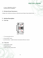
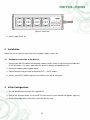
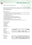
Warning
Unauthorized modification of this device can cause its damage!
• The manufacturer is not responsible for possible damage caused by improper usage or usage in
unsuitable environment.
• Device has been designed for indoor use only.
• Do not use the device during the strong vibrations.
• If your device does not work properly, please contact your local dealer.
Contents
1 Introduction
1.1 Features . . . . . . . . . . . . . . . . . . . . . . . . . . . . . . . . . . . . . . . . . . . . . .
1.2 Specifications . . . . . . . . . . . . . . . . . . . . . . . . . . . . . . . . . . . . . . . . . . .
1.3 Minimum System Requirements . . . . . . . . . . . . . . . . . . . . . . . . . . . . . . . .
3
3
3
4
2 Interface Description
2.1 Side View . . . . . . . . . . . . . . . . . . . . . . . . . . . . . . . . . . . . . . . . . . . . .
2.2 Front View . . . . . . . . . . . . . . . . . . . . . . . . . . . . . . . . . . . . . . . . . . . . .
4
4
4
3 Installation
3.1 Hardware connection of the device . . . . . . . . . . . . . . . . . . . . . . . . . . . . . . .
5
5
4 Initial Configuration
5
5 Operation and Settings
5.1 Output control and settings . . . . . . . . . . . .
5.1.1 Output control . . . . . . . . . . . . . . .
5.1.2 Output status and configuration . . . . . .
5.2 System configuration . . . . . . . . . . . . . . . .
5.2.1 Configuration of network parameters . . .
5.2.2 E-mail configuration . . . . . . . . . . . .
5.2.3 Date and time settings . . . . . . . . . . .
5.2.4 Manage users . . . . . . . . . . . . . . .
5.2.5 Firmware update . . . . . . . . . . . . . .
5.3 Serial Port, Telnet/CGI command control . . . . .
5.3.1 Secure login . . . . . . . . . . . . . . . .
5.3.2 Communication via KSHELL interface . .
5.3.3 List of commands for control via KSHELL
5.3.4 CGI commands . . . . . . . . . . . . . . .
5.4 Manual control . . . . . . . . . . . . . . . . . . .
5.5 LED status indicators . . . . . . . . . . . . . . .
5.6 Troubleshooting . . . . . . . . . . . . . . . . . . .
5.6.1 Reset to factory defaults . . . . . . . . .
5.6.2 Firmware upgrade problem . . . . . . . .
5.6.3 Fuse replacement . . . . . . . . . . . . .
6 Liability
.
.
.
.
.
.
.
.
.
.
.
.
.
.
.
.
.
.
.
.
.
.
.
.
.
.
.
.
.
.
.
.
.
.
.
.
.
.
.
.
.
.
.
.
.
.
.
.
.
.
.
.
.
.
.
.
.
.
.
.
.
.
.
.
.
.
.
.
.
.
.
.
.
.
.
.
.
.
.
.
.
.
.
.
.
.
.
.
.
.
.
.
.
.
.
.
.
.
.
.
.
.
.
.
.
.
.
.
.
.
.
.
.
.
.
.
.
.
.
.
.
.
.
.
.
.
.
.
.
.
.
.
.
.
.
.
.
.
.
.
.
.
.
.
.
.
.
.
.
.
.
.
.
.
.
.
.
.
.
.
.
.
.
.
.
.
.
.
.
.
.
.
.
.
.
.
.
.
.
.
.
.
.
.
.
.
.
.
.
.
.
.
.
.
.
.
.
.
.
.
.
.
.
.
.
.
.
.
.
.
.
.
.
.
.
.
.
.
.
.
.
.
.
.
.
.
.
.
.
.
.
.
.
.
.
.
.
.
.
.
.
.
.
.
.
.
.
.
.
.
.
.
.
.
.
.
.
.
.
.
.
.
.
.
.
.
.
.
.
.
.
.
.
.
.
.
.
.
.
.
.
.
.
.
.
.
.
.
.
.
.
.
.
.
.
.
.
.
.
.
.
.
.
.
.
.
.
.
.
.
.
.
.
.
.
.
.
.
.
.
.
.
.
.
.
.
.
.
.
.
.
.
.
.
.
.
.
.
.
.
.
.
.
.
.
.
.
.
.
.
.
.
.
.
.
.
.
.
.
.
.
.
.
.
.
.
.
.
.
.
.
.
.
.
.
.
.
.
.
.
.
.
.
.
.
.
.
.
.
.
.
.
.
.
.
.
.
.
.
.
.
.
.
.
.
.
.
.
.
.
.
.
.
.
.
.
.
.
.
.
.
.
.
.
.
.
.
.
.
.
.
.
.
.
.
.
.
.
.
.
.
.
.
.
.
.
.
.
.
.
.
.
.
.
.
.
.
.
.
.
7
7
7
8
10
10
11
12
13
14
15
15
15
16
19
20
20
20
20
20
21
21
2
1
Introduction
NETIO-230B is a power controller device that can be controlled remotely via Internet browser, Telnet, or
CGI commands. Thanks to the network management technology based on the IP protocol the user can
easily control or check power status of his devices (appliances) using the computer connected to local
network or the Internet. Because of web-based management, there is no need to install any special
additional software. Telnet interface could be used for convenient automatic control by an external
device.
Imagine you are traveling abroad and you can still control your electronic appliances like computers,
servers, routers, electric entrance gates, security/surveillance systems or any other 230V appliance
directly or using the timer.
1.1
Features
• Built-in web server
• Supports wide range of Internet browsers:
•
•
•
•
•
•
•
•
•
•
•
•
•
•
•
•
•
1.2
Internet Explorer
Mozilla Firefox
Opera
Google Chrome
Four switched power outputs (ports)
Four manual control buttons
Supported protocols: HTTP, SMTP, SNTP, DHCP, DNS and Telnet
CGI commands control
Secure login
Three levels of user access
LED indicators for actual status of each outlet
Safe design prevents from electric current injury, fireproof materials
Timer for scheduled output control
Settings for power-up status of each output (on/off)
Manual output control using buttons
Watchdog feature for restart of unresponsive network devices
E-mail notification
Specifications
• Input power: 230 V AC
• Max switched current: 10 A
• Latency: maximum 10 ms
3
• Latency: 300x60x90 mm (WxHxL)
• Network interface:10/100 Mbit/s
1.3
Minimum System Requirements
Computer with installed Internet browser (Microsoft Internet Explorer, Opera, Mozilla Firefox, . . . )
2
Interface Description
2.1
Side View
Figure 1: side view
1. Fuse housing for main fuse
2. Device ON/OFF switch
3. RJ-45 connector – network interface for connection to Ethernet / Internet.
2.2
Front View
1. Switched power outputs
2. Four LED indicators
3. Buttons for manual output control
4
Figure 2: front view
4. Power supply 230 V AC
3
Installation
Before the first use, please make sure that: the power supply is 230 V AC.
3.1
Hardware connection of the device
1. Connect your NETIO-230B to the computer network (switch, router) using the Ethernet cable with
RJ-45 connectors. Use cross cable when the device is directly connected to the PC.
2. Connect the power cable to power outlet.
3. Connect devices that you want to control to OUT1 – OUT4 outputs.
4. Turn on your NETIO-230B using the main switch on the side of the device.
4
Initial Configuration
1. Run file NetioDiscover.exe from the supplied CD.
2. Click on the Discover button. List of all NETIO units present in your network will appear. (figure 3)
3. Choose the proper device from the list and click Device setup.
5
Figure 3: device set-up
Figure 4: set-up of network parameters
Window appears for set-up of network parameters - IP address, Subnet mask and Gateway. (Figure 4)
After input of requested changes based on your network environment, click Change IP. Changes
are made to the device settings. Utility will update the settings of your NETIO and show device
list with changed parameters. If there is DHCP server in your network and you are not willing
to change the set-up network parameters manually, just skip to the next step. The default
IP address is 192.168.10.100 – if there is no DHCP server in the network. If a DHCP server
exists, the device gets the address from the DHCP.
4. Web management could be opened both by typing the IP address of NETIO into your internet
browser or by double clicking on the device name in the NETIO discover utility.
6
5. The login page appears. Input the User Name, Password into the login page and click OK. You
jump to the device web.
Default user name is admin, password admin
Figure 5: login page
For login to web interface, JavaScript support must run on the browser.
5
Operation and Settings
5.1
5.1.1
Output control and settings
Output control
Click on Manual Control the Menu on the left side. Output Manual control page will show up.(figure 6)
NETIO-230B can control all four outputs at the same time. Choose which ports should be turned
ON/OFF and click Apply. If you would like only to restart the devices connected to the specific ports,
tick Interrupt and then click Apply. Selected ports will interrupt for the time specified in the Status &
configuration page and then will turn on again.
Please note that you can interrupt for a short time only ports, which are turned ON. If you would
like to turn ON/OFF manually or restart, make sure that the correspondingManual checkbox is ticked. If
7
Figure 6: manual control
not, the device does not accept manual output control requests and only scheduled switching and the
Watchdog feature are in operation. PressingAll off button will turn all outputs OFF.
5.1.2
Output status and configuration
On the left side of the window, click Status & configuration, the list of ports and status information
appears in the right window.
To setup specific port select in the column Select and click Modify.
On the new page that will appear you can set up detailed parameters of this specific port. Significance of the individual parameters is described in the following text.
Output configuration
• No.: Port number (0 - 3)
• Name: Port (Output) name
• PON state: Default output state after NETIO power on – if you tick the checkbox, the port will be
turned ON after the NETIO start or restart.
• Manual control: If you select this option it will be possible to control the output manually.
• Time control: If you select this option the port will be switched on by timer the configuration of
which is given below.
• Timer mode: Specifies how often the scheduled ON/OFF switching will be performed. Options:ONCE- event will occur only once, DAILY - event will be triggered everyday or WEEKLY event will be triggered once per week.
8
Figure 7: set-up ports
Figure 8: output configuration
• ON time: date and time for switching the output ON, if you select DAILY mode, this is the date and
time of first execution
9
• OFF time: Date and time to switch the output OFF. If you select the DAILY mode, this is the date
and time of first execution
• Week schedule: Select in which weekdays the Timer control should be in operation.
• Interrupt delay: Time in seconds for which the output should be turned OFF when the Interrupt
function is used either in the manual mode or when the Watchdog feature is in operation.
Watchdog
Watchdog feature allows monitoring of proper operation of network devices. If the monitored device
does not respond to a Ping command within the specified time, the power outlet with enabled watchdog
will be turned OFF for a specified time and then switched back ON. To avoid cycle power OFF/ON of
defective monitored device, it is possible to setup maximum allowed number of output restarts (default
value 3).
•
•
•
•
•
•
•
•
Enable: Turning on the Watchdog feature.
IP address: IP address of the network device that will be monitored.
Timeout: Maximum Ping response time.
PON delay: Time (in seconds) for which the Watchdog feature will be inactive after the output
restart. During this interval the monitored device should recover its normal operation after being
restarted.
Ping interval: Interval (in seconds) in which the Ping requests to the monitored device will be
sent.
Max retry: Maximum allowed number of output restarts for the case that monitored device does
not respond to a Ping command. After the maximum number of retries is reached the output will
stay OFF.
Retry POFF: enables Max retry option
Send e-mail: Sends out an informative e-mail that the monitored device did not respond and was
restarted.
Save your new settings by pressing the Apply button.
5.2
System configuration
In this section the user can change network and e-mail parameters, system time, administrate user
accounts or perform the firmware upgrade.
5.2.1
Configuration of network parameters
Click Configuration link in the menu to change the system configuration.
10
Here, you can set up IP Address, Subnet Mask, Default Gateway and DNS Server according to your
network parameters. If you do not wish to setup the network parameters manually, you can Enable
DHCP to obtain requested parameters automatically from the DHCP server in your network.
The parameter Switch delay (x0.1s) specifies delay between triggering two outputs. It avoids overloading of the device supply by turning all outputs ON at the same time.
The selections KSHELL Port and WEB Port allow change of default output for access via telnet,
eventually, device web interface.
Device name allows you to insert the name of your device for easier identification in the future.
Firmware version is just informative and shows the current firmware version.
After you make requested changes on this page and click Apply the device will change the parameters and restart automatically. After the restart you will have to login again. Reset To Default button
restores factory default settings.
Figure 9:
5.2.2
E-mail configuration
Click Setup e-mail and the form for adjusting e-mail settings can be seen on the right. Please input
sender (From), and recipient (To) of e-mail message. Also input the SMTP server address that will be
used to send out the e-mail. The last field (Warning MSG) is used to input the subject of the e-mail
message sent.
Click Apply to save. You can check if e-mail setup is correct by pressing the Send test message
button.
Note: Current firmware version does not support SMTP authorization.
11
Figure 10: Setup e-mail
5.2.3
Date and time settings
Click Date & time in the menu and the system date and time settings will appear on the right.
NETIO-230B supports two methods of getting the right date and time values. It can be entered
manually or obtained automatically from the SNTP server.
Figure 11: Setup time and date
• SNTP enable: Enables time synchronization with SNTP server.
• SNTP status: SNTP server synchronization status:
• Synchronized: time successfully synchronized with SNTP server
• Not Synchronized: time successfully synchronized with SNTP server
12
•
•
•
•
•
Local time offset: Manual set-up of your time zone – time shift against GMT time in minutes.
Daylight saving time: Enables daylight saving time.
Daylight saving time start: Daylight saving time begin
Daylight saving time end : Daylight saving time end
Local time: mManual local time set-up with SNTP server synchronization off.
Daylight saving time and local time offset works both for automatic and SNTP set-up. If you do not
specify Local Time Offset, when the time synchronization with SNTP server is setup, Greenwich Mean
Time will be used.
5.2.4
Manage users
Figure 12: manage users
The category Manage users in System menu contains the configuration of user accounts. The device
supports three levels of user authorization (figure 12):
•
•
•
•
•
•
Admin: Full administration.
User: User that can control outputs (ports), but cannot change any system settings.
Guest: User who is not authorized to change any setting, but can only observe current port status
Add: addition of a new user
Modify: modification of password and authorization of selected user
Remove: removal of the selected user
13
5.2.5
Firmware update
The page Firmware Update is used to upload the new firmware into your NETIO-230B. After you click
the Firmware Update link in the menu, a warning message will appear on the right.
Figure 13: Firmware update
Continue by clicking on the Update button. The device will then switch to a new firmware upload
mode. After approximately three seconds the Continue button is activated. Click on it.
Figure 14:
14
Now insert the firmware file (xnetio.bin) and click Update. Approximately two minutes procedure of
firmware upload will follow. After the firmware upgrade is completed the device will restart automatically.
After the re-login you will be working with the new firmware version.
Figure 15:
5.3
5.3.1
Serial Port, Telnet/CGI command control
Secure login
NETIO-230B supports two login modes – open login and login with encrypted password. Encrypted
password can be used for Telnet, http and serial link control. Login via web interface is encrypted
automatically.
For secure login you first need to obtain the hash code from the device. You can obtain this code in
a return code after the connection via KSHELL, and/or CGI command hash.
To calculate the proper encrypted login password MD5 hash function is used: <username><password><hash>. It is 128-bit number transmitted as 32-digit hexadecimal number.
5.3.2
Communication via KSHELL interface
To connect to your NETIO-230B please follow these steps:
1. Open command prompt
2. Enter the command telnet 192.168.10.100 1234 (replace the address with the address of your
device, replace 1234 with the output set on the Netio for KSHELL)
3. The device should give you the reply like: 100 HELLO EB5D61F6 The last 8 characters constitute
the hash code needed for secure login with encrypted password.
4. You can login now by entering command login name password, where name is the user name and
password is your password. If you entered correct name and password the device should reply
250 OK. Now you are logged in and you can use commands to control your NETIO-230B.
15
Each communication session via KSHELL interface has limited validity. In case of no response for
about one minute, the session is terminated automatically. If you need to keep the session active, you
can use the command noop.
5.3.3
List of commands for control via KSHELL
login <name><password> User login with open password.
Example: Using login admin admin, you will login with username admin and password admin.
clogin <name><crypted password> User login with encrypted password.
version Shows firmware version.
alias Shows device name.
quit Logout. If system changes have been made, device restart is done.
reboot Logs out, closes the current session and restarts the device.
noop Function that maintains the connection, does not execute any operation. Suitable for use during
machine control of the device.
uptime Shows the device uptime.
port <output>[0/1/manual/int] Status and port setup:
•
•
•
•
If you enter only output number, output status shows (0 - OFF / 1 - ON)
Output number and 0/1 parameter - disables / enables output
Output number and ’manual’ parameter - enables manual output control
Output number and ’int’ parameter - interrupts output
Example: Command port 2 1 will turn ON output 2.
port list [xxxx] :
• Without any parameters it lists current status of all outputs
• xxxx command for simultaneous control of all ports - replace x with the commands:
• 0 - to turn the output OFF
• 1 - to turn the output ON
• i - to interrupt the output
• u - to leave the output without any change of its status
Example: Command port list 01ui will turn output 1 OFF, turn output 2 ON, output 3 will remain
unchanged and output 4 will be interrupted for a short while.
port setup<output>[<output name><mod:manual/timer><interrupt delay><PON status>]
Command for change of output parameters - significance of parameters is as follows:
16
• <output name> - Entered in quotation marks (also without them if it does not contain whitespaces).
• <mod:manual/timer> - Selection of output mode.
• <PON status> - Status after switching on the device: 0 - OFF / 1 - ON
Example: Command port setup 1 vystup 1“ manual 2 will set output 1 name output 1, enable
”
manual control, interruption interval to 2 seconds and power on state to ON.
port timer <output><time format>[ <mode: once/daily/weekly><on-time><off-time>] <week schedule>
Timer control:
• <output> - number of output to change
• <time format> - time format
• t - HH:MM:SS
• dt - YYYY/MM/DD,HH:MM:SS
• ux - xxxxxxxx ( unsigned long with 0x<hex>, 0<octal>prefix or decadic )
• <mode once/daily/weekly> - Selection of timer option.
• <on-time> - Output ON-time.
• <off-time> - Output OFF-time.
• <week sched.> - Number consisting of seven digits (0 or 1).; first digit stands for Monday
and the last one for Sunday
Example: The command port timer 3 t weekly 08:00:00 17:30:00 1111100 will enable Time
control on output 3. Each day from Monday till Friday at 8:00 AM output 3 will turn ON and turn
OFF at 5:30 PM.
port wd <output> Shows Watchdog settings for requested output in format:
<wd:
enable/disable><wd ip addr><wd timeout><wd PON delay><ping refresh><max retry><max retry poff:
enable/disable><send email: enable/disable>
port wd <output><wd: enable/disable> Enables / disables the Watchdog feature. Example: The
command port wd 4 enable will enable the Watchdog feature on output 4.
port wd<output>< wd:enable/disable><wd ip addr><wd timeout><wd PON delay><ping
interval><max retry><max retry poff:enable/disable><send email:enable/disable> Sets
all parameters of the Watchdog feature for requested output. The significance of the parameters
is as follows:
•
•
•
•
•
<output> - number of set output
<wd: enable/disable> - enable/disable watchdog function on given portu
<wd ip addr> - IP address of monitored device in seconds
<wd timeout> - maximum response time of monitored device
<wd POn delay> - Time (in seconds) for which the Watchdog feature will be inactive after
output restart. During this interval, the monitored device should recover to its normal operation after being restarted.
17
• <ping interval> - Interval (in seconds) in which the Ping requests to the monitored device will
be sent.
• <max retry> - Maximum allowed number of output restarts for the case that monitored device
does not respond to a Ping command. After the maximum number of retries is reached the
output will stay OFF.
• <max retry poff: enable/disable> - enable/disable the function max retry
• <send email: enable/disable> - enable/disable sending of e-mail messages unavailability of
monitored device, eventually, upon overrun of the max retry value
Example: The command port wd 2 enable 192.168.10.101 10 30 1 3 enable enable nable
enable will enable the Watchdog feature on output 2. Device on address 192.168.10.101 will be
monitored. Max Ping response time of monitored device will be 10 seconds. Ping commands will
be sent in 1 second intervals. If the monitored device won’t respond in 10 seconds, output 2 will
be turned OFF for 30 seconds. If the device will fail to respond to Ping commands after the third
restart the output will stay OFF. You will be notified by warning e-mail after each reset of the output.
system eth Shows current network interface setup in format: <dhcp/manual><ip address><mask><gateway>
system eth <dhcp/manual>[<ip address><mask><gateway>] Setup of the network interface parameters – IP address, subnet mask and gate way parameters are needed to pass only if manual
mode is entered. To allow changed values to take effect you must restart the device by typing the
reboot command or turning it off and on again.
Example: The command system eth manual 192.168.10.150 255.255.255.0 192.168.10.1 will
set IP address 192.168.10.150, subnet mask 255.255.255.0 and default gateway 192.168.10.1.
email server <ip/domain server address> Sets IP address or domain name of the SMTP server.
system discover <enable/disable> Enables / Disable visibility of the device for the network Discover
utility.
system discover hows if the option system discover is activated or deactivated.
system swdelay <delay> Sets delay between triggering two outputs. Value expressed in tenths of
seconds.
system swdelay Shows current delay between triggering two outputs.
system dns <ip> Sets IP address of the DNS server. To allow changed values to take effect, you must
restart the device by typing the reboot command or switching NETIO off and on again.
system dns Shows current IP address of the DNS server.
system dst Shows current
rrrr/mm/dd,hh:mm:ss
daylight
saving
time
setting
in
format:
system dst <enable/disble> Enables/disables daylight saving time
system dst begin yyyy/mm/dd,hh:mm:ss Sets daylight saving time beginning
18
enabled/disabled
system dst end yyyy/mm/dd,hh:mm:ss Sets daylight saving time end
system sntp Shows current SNTP client settings.
system sntp <enable/disable><sntp ip/domain> hows current SNTP client settings. Enables (enable), or disables (disable) time synchronization with SNTP server. Server address can be entered
both as IP address or domain name.
system time <YYYY/MM/DD,HH:MM:SS> Sets local time.
system time Shows current local time.
system timezone <+/-offset> Sets local time zone. Time zone offset is presented in seconds.
system timezone Shows current local time zone offset from UTC. Presented value is in seconds.
system update Switches the system to firmware upgrade mode.
system reset to default Resets all device settings to factory default values. After sending this command, factory default values are restored and the system restarts.
system webport <port>
system kashport <port>
5.3.4
CGI commands
NETIO-230B can easily be integrated into your applications using CGI commands.
CGI command device control uses the following command format:
http://<IPaddress>/tgi/control.tgi?<command >
Replace the IP address of your device with the string <IP address>. The <command>string is the
actual command.
List of CGI commands:
hash=hash Hash string request, hash is needed to generate encrypted password. Command returns
<html>hash </html>.
login=<p / c>:<user name>:<password> Login to the device. By typing login=plain you choose
to login with unencrypted password. For encrypted login, select the command login=crypted. Further
command parameters are login name and password. Command return values are:
•
•
•
•
<html>555 FORBIDDEN</html> You are not logged in or bad command.
<html>100 HELLO</html> - Successful login.
<html>553 INVALID LOGIN</html> - Incorrect user name / password.
<html>554 ALREADY LOGGED IN</html> - You are trying to log in although you are already
logged in.
19
quit= quit Logout. Return value is <html>110 BYE</html>.
port=list / xxxx> Parameter list shows output status in the format <html>port1 port2 port3 port4
</html>, where port1 to port4 are values 0 for OFF and 1 for ON. Parameter xxxx is a string for changing
status of outputs. Instead the x character insert 0,1,u or i like in case of setting the outputs via Telnet
interface.
All commands can be shortened to its first character. Possible short hands are stated in bold.
Example: command port=list can be shortened to p=l.
5.4
Manual control
In addition to PC, outputs could be also controlled manually using the four buttons on the front panel. To
switch the given output ON or OFF, press the button for 2 seconds. If the output is OFF, it comes ON, if
it was ON, it goes OFF. The buttons correspond to outlets 1-4, from left to right.
5.5
LED status indicators
The LED indicators on the device are used to inform the user not only about the output status, but also
communicate certain system status information. Green LED - the diodes provide information about the
actual status of the output. If the green diodes 1-4 are lighted, the port is on. If the green diodes are not
lighted, the port is off. Red LED informs the user about various device states. The following states are
possible:
• Red LED 1 on - initialization of network interface; if it remains on after switch-on, the network is
unavailable.
• Red LED 2 on - sending of request to DHCP
• Red LED 3 blinking - fw upgrade in progress
• Red LED 4 on - device in fw upgrade mode
5.6
5.6.1
Troubleshooting
Reset to factory defaults
If you forget administrator’s password you can reset the device to factory default values in order to regain
access to it. You do this by pressing both buttons 1 and 2 at the same time with device on. Hold the
buttons until you hear a beep. During reset, all the led diodes are red. After reset, the LED indicators go
off.
5.6.2
Firmware upgrade problem
If a problem arise during firmware upgrade (e.g. network failure, or switch-off of the device before
completion of update), it is possible to force start the device in firmware upgrade mode. You do this
20
by pressing button 4 when switching on the device. Hold the button until you hear a beep. After this,
connect to the device IP address via the browser. Continue to insert the firmware file according to
chapter 5.2.5.
5.6.3
Fuse replacement
If your NETIO-230B will not work and the main switch is not lighted, it is possible that the fuse has blown.
Before you proceed to fuse replacement, check whether the NETIO-230B device is TURNED OFF and
DISCONNECTED FROM THE NETWORK. Also disconnect all devices connected to the NETIO outputs.
To replace the fuse, unscrew the fuse holder (ideally using a flat screwdriver). Always use an identical
replacement fuse (250V 10A type F). After insertion of the correct fuse, replace the plastic holder and
screw it on. Connect the power supply cable and try to switch on the device. Before you connect all
devices back to the NETIO outputs make sure that the fuse was not destroyed by connected device that
is defective.
6
Liability
The manufacturer cannot be held responsible for any technical or typographical errors in the user manual and reserves the right to make changes to the product and manuals without prior notice. The
manufacturer makes no warranty of any kind with regard to the information contained within this document, including, but not limited to, the implied warranties of merchantability and fitness for any particular
purpose.
Web: http://www.koukaam.se
E-mail: [email protected]
Technical support: [email protected]
c
KOUKAAM
a.s., Miroslav Lı́zner