1
Table of Contents
Preface ......................................................................................................................................... 5
Important notices ............................................................................................................................ 6
1. Introduction ............................................................................................................................... 7
1.1. Characteristics ........................................................................................................... 7
1.2. Specifications ............................................................................................................ 8
1.3. System requirements ................................................................................................... 8
2. Control and configuration ......................................................................................................... 10
2.1. Outlets .................................................................................................................... 10
Outlet control .................................................................................................... 10
General outlet settings ........................................................................................ 12
Timer ............................................................................................................... 13
Watchdog ........................................................................................................ 14
Power consumption ............................................................................................ 16
2.2. Bluetooth ................................................................................................................. 17
Pairing with the Bluetooth device ......................................................................... 18
2.3. User account management ........................................................................................ 19
2.4. Schedules ................................................................................................................ 21
2.5. Actions ................................................................................................................... 23
2.6. Device configuration ................................................................................................. 24
Network Mode .................................................................................................. 24
Wi-Fi ............................................................................................................... 25
Network ........................................................................................................... 26
Secure connection .............................................................................................. 28
Date/Time ........................................................................................................ 28
E-mail .............................................................................................................. 29
Firmware .......................................................................................................... 31
System settings .................................................................................................. 33
2.7. Log ........................................................................................................................ 34
2.8. Manual outlet control ............................................................................................... 35
2.9. Status LED diodes .................................................................................................... 35
2.10. Acoustic signalization ............................................................................................. 35
2.11. Communication via KSHELL interface ........................................................................ 36
KSHELL commands overview ............................................................................... 36
2.12. Troubleshooting ...................................................................................................... 37
Forgotten password. Restore Factory Defaults. ....................................................... 37
Problem with firmware upgrade .......................................................................... 37
Resetting the fuse ............................................................................................... 37
A. Description of the Lua language ................................................................................................ 38
A.1. Basics of the Lua language ....................................................................................... 38
A.2. Specifics of the Lua environment in NETIO4 ................................................................ 39
A.3. Controlling outlets .................................................................................................... 39
Switching outlets ................................................................................................ 39
Resetting outlets ................................................................................................. 39
A.4. NETIO4 device variables .......................................................................................... 40
Variables for added Bluetooth devices .................................................................. 40
A.5. NETIO4 device actions ............................................................................................. 41
A.6. IncomingCgi event as an action trigger ...................................................................... 41
A.7. Other action triggers ................................................................................................ 42
A.8. Special variables ..................................................................................................... 42
A.9. Functions and libraries ............................................................................................. 43
2
delay ...............................................................................................................
milliDelay .........................................................................................................
log ...................................................................................................................
logf ..................................................................................................................
mail .................................................................................................................
ping .................................................................................................................
A.10. Examples ..............................................................................................................
Action for processing incoming CGI requests with a change of the states of outlets
..........................................................................................................................
Action for controlling an outlet on the basis of the accessibility of another device in
the network .......................................................................................................
Action for cyclic outlet control .............................................................................
Actions to control outlets based on the availability of Bluetooth devices ......................
Conclusion ...................................................................................................................................
Declaration of Conformity .............................................................................................................
43
44
44
45
45
46
47
47
47
48
48
50
51
3
List of Figures
1. Outlet control ..........................................................................................................................
2. General outlet settings ..............................................................................................................
3. Timer settings ..........................................................................................................................
4. Watchdog settings ....................................................................................................................
5. Power consumption ..................................................................................................................
6. Power consumption Counter Reset ..............................................................................................
7. Bluetooth device management ....................................................................................................
8. Add user ................................................................................................................................
9. Detailed user permissions management .......................................................................................
10. Adding custom schedule .........................................................................................................
11. Adding interval in second precision ..........................................................................................
12. Adding action ........................................................................................................................
13. Network mode setting .............................................................................................................
14. Wi-Fi setting ..........................................................................................................................
15. Network configuration ............................................................................................................
16. Secure connection setting ........................................................................................................
17. Date and time configuration ....................................................................................................
18. E-mail configuration ...............................................................................................................
19. Details about installed firmware ...............................................................................................
20. Firmware update from file .......................................................................................................
21. System settings .......................................................................................................................
22. Log .......................................................................................................................................
23. output of the log() function ......................................................................................................
11
13
14
15
16
17
18
19
20
21
22
23
24
25
27
28
29
30
31
32
33
34
38
4
Preface
Thank you for purchasing a KOUKAAM product. To prevent incorrect installation or improper use of equipment
please carefully read this User Manual and the Quick Installation Guide, which is included in the package. This
will prevent any wrong installation or incorrect usage of NETIO4.
Carefully read the following notice. The device you have purchased operates under a certain voltage. Incorrect
manipulation with the device may result in damage to the device or it can cause injury or even death to the
person handling it.
5
Important notices
1. The manufacturer is not liable for potential damage caused by incorrect usage or placing the device in
an unsuitable environment.
2. The device is not intended for usage outdoors.
3. Do not use the device in an environment with strong vibrations.
4. Unauthorized modification of this device can damage it or cause fire.
5. Prevent contact with fluids; do not expose the device to high temperatures.
6. Protect the device from falling.
7. Only devices approved for use in the electricity network may be connected.
8. If the device malfunctions, disconnect it from the electric power supply and contact your vendor.
6
1. Introduction
NETIO4 is a multifunctional power supply controller. This device is intended to control power supply via web
interface or CGI commands. Thanks to the network administration technology based on IP protocol basis, the
user can control or provide a power supply to a connected external device (appliance) via a computer connected
to the LAN or Internet network. No special software is necessary to control the device, the Web interface is
already integrated in the firmware. Using the web interface, you can easily control and set the entire device and
individual outlets.
Imagine that you are travelling around the world and you can remotely or via a timer control the power supply
to your electrical appliances such as computers, servers, routers, electric gates, security/surveillance system or
other appliances.
NETIO4 is available in several versions with different outlet types. Note that in this user manual, all screenshots
of the user web interface contains only one outlet type and outlets on your device may differ from those shown
in this user manual.
This manual is meant for the following models:
NETIO4
Basic model with integrated Wi-Fi.
NETIO4 All
NETIO4 with power consumption meter for each outlet and Bluetooth 4.0 LE support.
1.1. Characteristics
• Four manageable power outlets.
• Standardized power outlets allow direct connection of powered device.
• Available outlets for DE, FR, CZ, US or UK.
• Every outlet has separate LED status indicator and power switch.
• Robust design, every outlet and inlet has own voltage over-protection.
• 1.2m long power-cord and power off switch on the device.
• Re-settable 15A fuse.
• Possibility to login using an encrypted password.
• Bluetooth 4.0 LE support for expanders and sensors (NETIO4 All only).
• Independent power consumption meter for every outlet (NETIO4 All only).
• LED indicator for Wi-Fi and Bluetooth network status.
• Watchdog for device network status monitoring with reboot option.
• User defined schedules for timing of the outlet power.
• Previous state of the outlet is set after reboot or restart.
7
Introduction
• Integration by CGI commands. NETIO4 can be controlled by CGIs and can control other devices by CGIs.
• Integrated scripting by LUA for system integration and customization by system integrators.
• Advanced integration by XML API, NDA obligatory.
• E-mail notification about switching the outlets, watchdog/timer action.
• User accounts with configurable privileges.
• Localized user interface CZ, EN, DE, ES, IT.
• iOS and Android mobile application for remote outlet control.
• Supported protocols HTTP, HTTPS, SMTP, DNS, NTP, UPnP, DHCP
1.2. Specifications
Power supply voltage:
90 - 250 V AC
Maximum switched current:
EU – 15 A total / 8 A per each outlet
US – 15 A total / 12 A per each outlet
Consumption:
4.1 W
Network interface:
1x RJ-45 10/100 Mbit/s
Wi-Fi 802.11b/g/n 2,4 GHz
Bluetooth 4.0 LE 2.4 GHz (NETIO4 All only)
Antennas:
1x fixed antenna with 2 dB gain (NETIO4 only)
2x antenna with 3 dB gain (one for WI-FI, one for BT) connected over SMAreverse F connector (NETIO4 All only)
Dimensions:
302 × 58 × 90 mm (h × w × d)
11,89 x 2,283 x 3,543 inches (h × w × d)
Operating temperature:
0 - 50 °C
32 - 122 °F
1.3. System requirements
• Supported Internet browsers:
• Internet Explorer 9 or later version
8
Introduction
• Mozilla Firefox 20 or later version
• Google Chrome 26 or later version
• Safari 5.1 or later version
• Computer with supported Internet browser with JavaScript support enabled.
9
2. Control and configuration
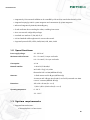
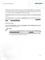
Mobile application
Install mobile application NETIO Mobile to control your NETIO4 from your mobile device. The
application is for mobile devices with operating system Android (version 2.0 or later) or iOS (version
5.1 or later). For further information, visit http://www.netio-products.com/en/all-products/netiomobile/. Use link below to download the application.
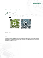
2.1. Outlets
Outlet control
In the left menu, choose Outlets item. You will be provided with the outlet overview. Each outlet and its automatic
functions can be controlled by four associated buttons next to each outlet. All outlets at once are controlled by
two buttons at the bottom of the page.
10
Control and configuration
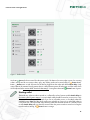
Figure 1. Outlet control
Use button
Power for direct control of outlet power supply. The button of an active outlet is green, for a starting
outlet is orange and for an inactive outlet is grey. Any starting outlet can be turned off by its
Power button.
Button
Restart turns on and off power for the device plugged into the outlet with defined Reset delay. Only
active outlet can be restarted. During restart, there is a delay between power off and power on of the outlet, which
can be adjusted in the section called “General outlet settings”. During the outlet restart,
Restart button is green.
Starting outlet
The actual time, when an outlet is turned on, is affected by value of system variable Switch delay (in
the section called “System settings”) in case multiple outlets should be turned on at once or in a very
short time. This can happen for example if you turn on all outlets at once, or if multiple outlets has
enabled function Timer and they have set the same schedule or if you turn on individual outlets in
a very short time. The second and every following outlet that should be turned on is actually turned
on after Switch delay will pass from the moment when the previous outlet is turned on. During the
time the outlet is starting, its
Power button is orange.
11
Control and configuration
All outlets can be controlled at once by means of two icons at the page bottom. Depending on current outlet state,
it is possible either to power off or power on all outlets and also to restart them. If there is at least one outlet on,
you will turn off all outlets at once by clicking the
Power button. If all outlets are off, this button can be used
to turn all outlets on. Click on the
Restart button to restart all active outlets.
After restart of your NETIO4 or when it starts after an unexpected switch off (e.g. in case of power loss), manually
controlled outlets will be in their previous state. Outlets controlled by timer will be in state according to the schedule
of the timer.
The two remaining buttons control
Timer and
Watchdog automatic functions. Turned on function is
represented by green colour of its button. First, you need to set these functions for each outlet in the section called
“Timer” and in the section called “Watchdog”.
General outlet settings
Use panel
General settings to configure various outlet related settings. Outlet name serves for outlet
identification and is displayed above its control icons. Reset delay is a number of seconds to wait between power
off and power on during outlet restart cycle.
Note
According to set values of Reset delay at particular outlet and system variable Switch delay (in the
section called “System settings”), an outlet may be in state of Starting outlet. For example: outlet1
has set Reset delay to 2 seconds, outlet2 to 5 seconds. System switch delay is set to 5 seconds. If
user resets both outlets at once, outlet1 will be on in 2 seconds but outlet2 will be on in 7 seconds.
To 5 second that represent Reset delay of the outlet, will be added 2 more second from the Switch
delay, that has started after outlet1 has been turned on.
12
Control and configuration
Figure 2. General outlet settings
Save configuration changes by clicking Save changes button.
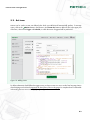
Timer
Timer function allows for an outlet to be power on/off at certain times. Choose a schedule to decide when
an outlet should be active. When a schedule is chosen, its details are then graphically displayed. You can see
in which time intervals will be the outlet active. Confirm the change by clicking the Save changes button. After
saving, the timer will be automatically activated and the outlet will be set in accordance with it. Should it be the
outlet turned off by activating the timer, you have to further confirm the change.
You cannot change schedules while setting the timer. To change schedules, use Edit schedules button.
You can turn on/off the timer by clicking
Timer button at particular outlet. If you manually turn off the timer,
the outlet remains in its current state, but will be controlled manually. If you manually turn on the timer, the outlet
will be set in accordance with it.
Automatic timer disabling
Note that by switching the outlet by
Power button, the timer of the outlet will be also disabled.
You will be inform about this in the following confirmation dialog by default.
13
Control and configuration
Figure 3. Timer settings
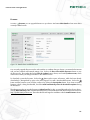
Watchdog
Use
Watchdog function to monitor various network devices. If the monitored device is unavailable, the
corresponding outlet will be turned off and on. The monitored device is considered unavailable if it does not
respond to Ping (Ping is used to test reachability of a host on a computer network) request in a given time interval.
The delay between power off and power on is configurable. It is possible to limit number of outlet restarts so
that it does not happen infinitely.
14
Control and configuration
Figure 4. Watchdog settings
IP address
IP address of monitored device.
Ping Interval
How often will be Ping query sent to the monitored device (in seconds).
Ping Timeout
When no responses to Ping requests arrive from the moment last response
was received in the period of the ping timeout (in seconds) interval, the
connected device is considered unreachable and the outlet is reset.
Power-on delay
Watchdog will postpone querying monitored device for this many seconds
after outlet power up, so that the device can fully start up.
After X resets
Limits the number of restarts and after is the limit reached, the Watchdog
stops reset the outlet to prevent periodic restarts (when controlled device
fails).
Turn the watchdog off
After the limit is reached, the Watchdog will be turned off and the outlet
remains on.
Turn the outlet off
After the limit is reached, the outlet will be turned off and the Watchdog
remains on. If the outlet has been controlled by timer, the timer will be also
turned off.
Turn both the watchdog and the
outlet off
After the limit is reached, both the Watchdog and the outlet will be turned
off. If the outlet has been controlled by timer, the timer will be also turned off.
15
Control and configuration
Send e-mail when device doesn't
respond
Sends e-mail every time when controlled device doesn't respond and outlet
restart is necessary. You need to have correctly set email settings (in the
section called “E-mail”) for this option to work.
Save configuration changes by clicking Save changes button. After saving, the function will be automatically
turned on. The Watchdog function can be manually turned on or off by clicking the
Watchdog button next
to the outlet.
Warning
Note that that function is active (thus sends Ping requests) only when the outlet is active too. If the
timer is not set on the outlet, you have to turn on the outlet manually. There is the
Link button,
which you can use to go to IP address of the monitored device, next to the name of the outlet which
is active and has also active the Watchdog function.
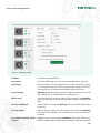
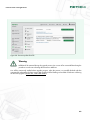
Power consumption
For selected models only
This function is available for selected models of NETIO4 series only. Please make sure that this
function is supported by your model. A list of models can be found in Chapter 1, Introduction.
Figure 5. Power consumption
16
Control and configuration
Use this function to gain access to current and cumulative power consumption of connected devices. The power
consumption is displayed on the right next to outlet control buttons. The upper reading is the Current power
consumption in Watts (W) of the device connected to the particular outlet. In the lower part of the screen, next
to the group outlet control buttons, is the reading for the current power consumption for all outlets. For an outlet,
which is turned off, is the current power consumption always 0 W.
The lower reading next to each outlet is the Cumulative power consumption in Watt hours (Wh), or in kilowatt
hours (kWh), for given time interval, in other words the aggregate power consumption of a device connected
to the outlet from the given date up to the present. By default settings, the cumulative power consumption is
measured from the first start of NETIO4, if automatic data and time synchronization from the NTP server has been
successful. Make sure that your date and time has been correctly set in the section called “Date/Time”. To adjust
the beginning of the power measurement, go to
general outlet settings and click on the Reset Counter button.
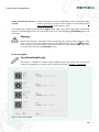
Figure 6. Power consumption Counter Reset
2.2. Bluetooth
Selected NETIO4 models supports up to three Bluetooth 4.0 LE (hereinafter BT) devices. You can use Actions
(described in Section 2.5, “Actions”) to react on paired BT devices vicinity. Actions can be used for example to
automatic garage gate opening or light control on the basis of your BT device availability.
For selected models only
Support for Bluetooth 4.0 LE devices is available for selected models of NETIO4 series only. Please
make sure that this function is supported by your model. A list of models can be found in Chapter 1,
Introduction.
17
Control and configuration
User actions for BT devices can react to Device reconnected or Device disconnected events or the value of a
global variable devices.<sensorName>.connected. A more detailed description can be found in Appendix A,
Description of the Lua language.
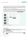
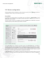
Pairing with the Bluetooth device
On the left menu, go to Bluetooth. Then click on Turn Bluetooth On to activate it. Make sure that all your BT
devices are switched into discoverable mode and are ready for pairing. Once your devices are ready, press
Search for Devices.
Newly scanned BT devices can be added by clicking on the name of detected device. A dialog box for
entering your own device name and a PIN code appears. After entering the name and PIN (see your device
documentation), press Add button which will pair your BT device with NETIO4.
Figure 7. Bluetooth device management
18
Control and configuration
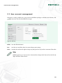
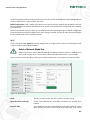
2.3. User account management
If the device is used by multiple users, using accounts with different privileges is advised. In the left menu, click
Users menu item. There are three different user types:
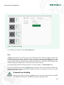
Figure 8. Add user
Admin
User with full authorization
User
User that can control the outlets, but cannot change system settings
Guest
User that does not have the rights to change any settings and can only see the current state of the outlets
Note
NETIO4 supports up to 5 user accounts. Username have to begin with a letter and can include only
digits and letters without diacritic.
19
Control and configuration
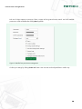
Pick one of above options as necessary. There is option of finer grained access control. List of all available
permissions will be available after clicking More hyperlink:
Figure 9. Detailed user permissions management
Confirm your settings by clicking Create user button. User accounts can be adjusted later in similar way.
20
Control and configuration
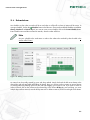
2.4. Schedules
Use schedules to plan when an outlet will be on and when it will be off or where an action will be active. To
manage schedules, click on the Schedules button in the left menu. There are three default schedules on NETIO4:
Always, Weekend and Work days. If you want to create a new schedule, click on the Create schedule button.
Enter schedule name and then create time intervals, when the outlet will be on.
Note
Set your schedule to the outlet timer in order to the outlet to be switched by that schedule in the
section called “Timer”.
Figure 10. Adding custom schedule
An interval can be quickly created by press and drag method. Simply click with the left mouse button to the
desired day and time and while still holding the button, drag your mouse to side to create an interval. Resize
an existing interval by holding its front or rear end and dragging your mouse to side. If you want to create an
24 hour interval, click on the cell next to the selected day in the column All day. By press and drag, you cover
multiple days with one interval, even the all day intervals. To delete an interval, click on it with right mouse button.
21
Control and configuration
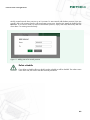
Quickly created intervals have precision up to 10 minutes. To enter interval with absolute precision (up to one
second), click on the existing interval to edit it and enter precise times. Save the new settings by clicking on the
OK button. If you want to create new interval with absolute precision, simply click to the desired day and time
where there is no existing interval already.
Figure 11. Adding interval in second precision
Delete schedule
If you delete a schedule, all timers which have this schedule set will be disabled. The outlets remain
in the same state, but will be controlled manually henceforth.
22
Control and configuration
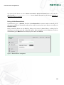
2.5. Actions
Actions can be used to create user-defined rules which your NETIO4 will automatically perform. To manage
action, click on the
Actions button in the left menu. Use Create rule button to add new rule. In the upper part
of the form, select action Trigger and Schedule, in which the action if triggered will be performed.
Figure 12. Adding action
To define what action should follow the trigger event, you have to write it in source code of Lua language. Basics
of Lua language can be found in Appendix A, Description of the Lua language. For simple and more comfortable
code writing, the Lua source code highlighting is supported.
23
Control and configuration
2.6. Device configuration
Please pay attention to device configuration, so that it can function properly. Click on
to display the submenu, where you can further set your device.
Settings in the left menu
Network Mode
To properly set up network interfaces of your NETIO4, begin with clicking the
Network Mode in the left
Settings menu. You can choose from four different network modes based on if and how do you want to use
Ethernet and/or Wi-Fi interface.
If you do not want to use Wi-Fi on your NETIO4 at all, simply select Cable mode. Your NETIO4 is connected via
the Ethernet (primary network interface) only and Wi-Fi is turned off.
Figure 13. Network mode setting
If you prefer NETIO4 to be accessible via local Wi-Fi network, select Wi-Fi Client mode. Your NETIO4 is
connected via the Wi-Fi (primary network interface). The Ethernet (secondary network interface) has a separate
network range and is used only for fallback access to your NETIO4. The Ethernet interface has static IP address
192.168.2.78 and runs its own DHCP server on network 192.168.2.0/24. Be advised that there is no routing
between Ethernet and Wi-Fi networks, so any device connected via the Ethernet interface cannot be accessed
from the Wi-Fi network through your NETIO4 (Do not bridge Wi-Fi to Ethernet).
In Wi-Fi Access Point mode, your NETIO4 is connected via the Ethernet (primary network interface) as in Cable
mode, but it is also serving as Wi-Fi Access Point at the same time. Other devices can connect to your NETIO4 via
24
Control and configuration
the Wi-Fi (secondary network interface) and have access to the network of the Ethernet interface (Bridge Ethernet
to Wi-Fi). DHCP server is not provided in this mode.
NETIO Configuration mode is similar to the Wi-Fi Access Point, but the two networks are separated in this case
(Do not bridge Ethernet to Wi-Fi) and DHCP server on network 192.168.2.0/24 is running on the Wi-Fi interface
(192.168.2.78).
Based on the network mode you select, you are asked to make corresponding changes in network configuration
of the selected primary network interface and in Wi-Fi settings if needed. You have to make all required changes
for the selected mode to be successfully activated.
Wi-Fi
Click on the Wi-Fi button
Wi-Fi in the left Settings menu to configure Wi-Fi. Based on which network mode
is active, configure entries described below.
Select a Network Mode first
Note that you have to select a Network Mode first to determine if Wi-Fi interface is enabled and in
which mode is active. Wi-Fi is turned off in Cable mode and the Wi-Fi menu is not accessible.
If you are not sure about this setting, contact your network administrator or your Internet connection provider.
Figure 14. Wi-Fi setting
Mode
This says in which mode is the Wi-Fi interface currently running.
Status (for client mode only)
Check if your NETIO4 has successfully connected to the selected Wi-Fi
network.
Network SSID
Type identifier of your Wi-Fi network (for AP mode only) or select an existing
Wi-Fi network you want to connect to (for client mode only). If you cannot
25
Control and configuration
see the network you want to connect to, try to use the Refresh button or enter
the network SSID manually (SSID is not broadcasted publicly).
Security
Select security of the Wi-Fi network, if used.
Encryption
Select the encryption type of the secured Wi-Fi network.
Password
Type password to the secured Wi-Fi network.
Channel (for AP mode only)
Select a channel of your Wi-Fi network.
Disable SSID broadcast (for AP
mode only)
Check this only if you want to hide your Wi-Fi network.
Save the settings by clicking the Save changes button.
Network
Click
Network in the left Settings menu. The simplest way how to set network parameters is to select Use
DHCP. If you have a DHCP server available on your network, all network parameters will be automatically set. To
make sure that device IP address remains the same, you can Set static IP address and other network parameters
manually.
26
Control and configuration
Figure 15. Network configuration
Then pay attention to domain settings. Enter a Hostname by which the device is identified in your network and
the name of your Domain. The current hostname is displayed left in the upper part of the web interface below
device type.
By checking the Enable UPnP presentation, you can enable presentation of your device via UPnP protocols, e.g.
in Network places in Windows. To set up a remote access to your NETIO4, check Enable UPnP port forwarding
and set the preferred web port. After saving changes in settings, you can see an IP address for the remote access
next to this checkbox.
Warning
Note that for the remote access to work, your router has to support control via UPnP protocols and
has to have set all required parameters. If you are not sure, contact your connection provider or
your network administrator.
It is recommended to disable Allow the discover tool to change network configuration setting as soon as you
discover the device and change its basic network parameters during initial configuration. Use button Locate to
27
Control and configuration
blink with the red LED diode of the outlet number 1. This makes the physical localization of the particular device
easier in case you have more than one device connected to your network.
Warning
Changes to network settings of the device may result in NETIO4 becoming unavailable at the current
address. Use the web discover http://discover.netio-products.com/ to find out its new address.
Save network settings by clicking Save changes button.
Secure connection
Click on the
Secure connection button in the left Settings menu. NETIO4 supports secure connection over
HTTPS. To use this feature, simply check Turn on secure connection (HTTPS) and confirm with Save changes
button. Self-signed certificate will be generated and you will be automatically redirected to device web interface.
All active connections will be terminated and then reconnected. You have to add permanent exception for the
created certificate in your browser.
Figure 16. Secure connection setting
You can view information about validity of the certificate and key fingerprint in the menu. If needed, new certificate
can be generated by Create New Certificate button. If you still want to use incoming CGI requests, check Allow
CGI-in to use insecure connection (HTTP).
Date/Time
Click
Date/Time in the left Settings menu. Specify the time zone first where your NETIO4 is used by selecting
the area and the city (this may differ from the time of the computer you are connecting from to your NETIO4).
NETIO4 supports two ways of time setting. You can set time manually or use a NTP server for automatic time
synchronization. Should you prefer automatic time synchronization, simply enter an address of desired NTP
28
Control and configuration
server. If you are not sure, leave the pre-selected pool.ntp.org. In case of manually set time, enter date in the format
YYYY-MM-DD and time in the format HH:MM:SS. You can also select to synchronize time with your computer.
Note
When your NETIO4 is connected to a network with access to the Internet during its first start,
system date and time will be automatically synchronized with default location in the prime meridian
timezone.
Figure 17. Date and time configuration
Save date and time settings by clicking Save changes button.
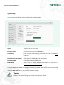
E-mail
Click
E-mail from the left Settings menu. The setting will be used to send e-mail reports from this device.
29
Control and configuration
Figure 18. E-mail configuration
SMTP server
Mailserver used to send messages.
Enable SMTP authentication
Check this option, if your mailserver requires authentication. You need to
enter Username and Password to your account on the mailserver.
Enable TLS encryption
Check if the SMTP server requires TLS encryption to login.
To
Email addresses of message recipients, use comma to separate each
address.
Use custom sender address
Use this if you want to use user defined sender address for all emails from
your device.
From
The address, that will be used as custom sender address.
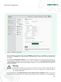
Should you require periodic reports about device state, check Send daily reports about NETIO health. The
message, which is sent every day after midnight, contains a summary of device load and log messages from
the past day.
Save e-mail settings by clicking Save changes button. It is possible to verify configuration by clicking Send test
e-mail button.
30
Control and configuration
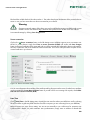
Firmware
In section
Firmware you can upgrade firmware on your device. Use button Show details to learn more about
currently installed version.
Figure 19. Details about installed firmware
You can easily upgrade firmware via the web interface on condition that your device is connected to the Internet
and you have entered valid network settings. First, click on the Show all available firmwares button to view
the firmware list. Then update the list by Check for updates button. Please, read carefully Release notes, which
contains the summary of changes and fixes in the selected version.
To download a particular firmware, click on the
button with its name. A firmware, which has been already
downloaded, is distinguished by green color and its legend. To install a downloaded firmware, click on the
button with the firmware name and then confirm it by clicking the Start Update button. If you want to install a
firmware, which is being downloaded, check the Install automatically when the download completes during
the download.
The alternate way how to upgrade firmware is Update from file. For this, you need the product key of your device click the Get Product Key button. Detailed instructions how to download the file with the firmware can be found on
http://update.netio-products.com. Then select the file and begin the installation with the Install Firmware button.
31
Control and configuration
Figure 20. Firmware update from file
Warning
NETIO4 will be restarted during the upgrade process. Do not turn off or restart NETIO4 during the
procedure in order not to damage the firmware or NETIO4.
You will be continuously notified about upgrade progress, when the process is successfully finished and then
automatically redirected to the login screen. LED of outlet 3 will be blinking red and LED of outlet 4 is red during
the firmware upgrade. (Section 2.9, “Status LED diodes”)
32
Control and configuration
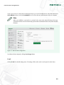
System settings
In this section, you can do basic settings and view basic system parameters.
Figure 21. System settings
Uptime
Time from the last device restart.
Firmware version
Current firmware version and Upgrade link.
Switch delay
Delay in seconds between turning on two and more outlets. To understand
how and when this variable influences turning on of outlets, see Starting
outlet note.
Disable manual control buttons
Select option for disabling physical control buttons.
Disable status LEDs
Select option to deactivate status LEDs.
Enable KSHELL
Select option to enabling KSHELL communication (see Section 2.11,
“Communication via KSHELL interface”).
Save the settings by clicking the Save changes button. Click on Restore Factory Defaults button to restore initial
settings of NETIO4. Note that all user settings will be deleted and default settings will be restored. You can check
Preserve network settings in confirm dialog window, so NETIO4 can be easily found after the restoration. By
clicking the Reset settings button, the process of restoration will begin.
Warning
NETIO4 will be restarted during the process of restoring factory defaults.
33
Control and configuration
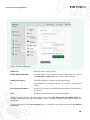
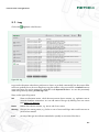
2.7. Log
Log button in the left menu.
Click on the
Figure 22. Log
Log provides information about device performance. Entries are ordered automatically from the newest. Older
entries are gradually shown when scrolling down using the scrollbar or the mouse wheel. Use Refresh button to
access new entries. Log can be exported as a HTML file via the Export to file button. You can also permanently
delete all log entries by clicking the Clear log button.
There are four types of log entries.
Info
These are information entries, which document common device activities, e.g. application start or
automatic database maintenance. You can add entries of this type by defining some user actions
(see Section 2.5, “Actions”).
Notice
Notices about devices activities, e.g. start or end of user session.
Warning
This type are warning entries, e.g. failure in case of unsuccessful login after invalid username or
password was entered.
Error
An entry of this type can indicate nonstandard or possibly an error state of the device .
34
Control and configuration
2.8. Manual outlet control
Apart from control via PC, the device can also be controlled using the four buttons on the front panel. The buttons
correspond to the outlets 1-4, from left to right. To switch the given outlet on or off, press the button for two
seconds. If the outlet was off, it will be turned on, if it was on, it will be turned off. The starting outlet will be
turned off by the button.
2.9. Status LED diodes
The status LED diodes on the device inform the user about the current state of the outlet and about specific states
of the device.
Each outlet has one two-coloured green-red LED diode above its control button. Green colour of the outlet LED
indicates the current state of the outlet. If the outlet LED is green, the outlet is on, if the outlet LED is not green, the
outlet is off. Green blinking outlet LED means that the outlet is restarting or starting.
Red colour of outlet LED diodes indicates specific states of the entire device. The following states are possible:
LED of outlet 1 is blinking red
Locate function was started.
LED of outlet 2 is red
DHCP failed.
LED of outlet 3 is blinking red
Firmware update is in progress.
LED of outlet 4 is red
Device is in service mode.
All outlet LEDs are red
NETIO4 is starting.
All outlet LEDs are blinking red
Reset of Factory Defaults is in progress.
The two remaining LED diodes indicate states of Wi-Fi and Bluetooth (for selected models [7] only) wireless
connection. If the
Wi-Fi LED is green, then Wi-Fi on you device is active, if not, then Wi-Fi is inactive. A
problem with Wi-Fi is indicated by the
LED blinking.
2.10. Acoustic signalization
The acoustic signalization will be activated in the following situations:
Beeps once
Device is starting.
Beeps twice
Service mode requested.
Start of reset to factory defaults.
Reset to factory defaults is done.
35
Control and configuration
2.11. Communication via KSHELL interface
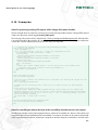
The connection procedure is shown in the following example:
1. Open the window with command line
2. Enter the command telnet 192.168.10.100 1234 (enter the address after the address of your device, will
1234 with the port, which you have set for KSHELL on the device)
3. The device should list a response similar to the following: 100 HELLO 00000000 - KSHELL V1.5
4. Now you can login with the command:
login name password
where name is the username and password is your password. If you have entered the correct username and
password, the device response is 250 OK. You are now logged on and you can control the NETIO device using
the commands from the following chapter.
Every communication session via KSHELL interface has limited validity. In case of inactivity of approximate
duration one minute, the session will be terminated automatically. If you need to keep the session active, you
can use the command noop.
KSHELL commands overview
login <name> <password>
Sign in using the plain password. Example: Use command login admin admin to log in with
username admin a password admin.
quit
Sign out. In case of changes in system settings, perform restart of the device.
noop
Keeps the connection alive, performs no action
port list [xxxx]
• without parameter gets the state of all ports
• xxxx is a command for control of all ports simultaneously - in place of x enter the
commands:
• 0 - deactivate output
• 1 - activate output
• i - call interruption of a given output
• u - leave output unchanged
36
Control and configuration
Example: The command port list 01ui deactivates output 1, activates output 2, leaves output 3
unchanged and interrupts output 4.
port <output> [0 | 1 | manual | int]
Gets and sets output state:
• if you enter only the number of the output without any parameter, the command gets the
output state (0 - off / 1 - on)
• output number with parameter 0/1 - turns the output on/off
• output number with parameter 'int' or 'i' - interrupts the output
Example: The command port 2 1 activates output 2.
2.12. Troubleshooting
Forgotten password. Restore Factory Defaults.
If you forget your password, it is possible to manually reset the device to factory defaults. This is done by pressing
and holding outlet buttons 1 and 2 with device on. Hold the buttons until the device beeps 2 times. During the
resetting process, all the outlet LED are blinking red. As soon as reset is completed, the device beeps 2 times.
Problem with firmware upgrade
If a problem occurs during the firmware upgrade (e.g. power failures, or switching off the device before the
upgrade is completed), it is possible to force the device into service mode. You can do this by pressing the outlet
button 4 on device boot. Hold the button until the device beeps 2 times. After this, connect to the device IP address
via the browser and click on Firmware button in top menu. Continue by uploading the firmware file as described
in Upgrade from file [31].
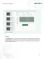
Resetting the fuse
If NETIO4 stops working and no indication LEDs are shining, it is possible that the rated current was exceeded
and the device was turned off. To prevent the current from damaging the device in this situation, the resettable
fuse interrupts power to your NETIO4. This is represented by releasing the resettable fuse button on the right side
of the device. Disconnect all devices connected to the outlets. Before turning your NETIO4 on again, you have to
wait for the device to cool down. This may take up to several minutes based on situation. Press the resettable fuse
button to turn NETIO4 on again. If it is not possible to press the button, wait for a moment for the device to cool
down. Check all connected devices for any malfunction which could cause that the rated current was exceeded
and power was interrupted before you plug them in again.
37
Appendix A. Description of the Lua language
NETIO4 uses the Lua scripting language, which allows users to extend the functionality of the device with user
actions. These actions can react to external signals such as incoming CGIs or events of the NETIO4 device itself,
for instance by sending an email to a user, initiating an outgoing CGI request to another device, etc.
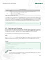
A.1. Basics of the Lua language
You can find an introduction to programming in the Lua language in the book Programming in Lua (http://
www.lua.org/pil/). The freely available version covers Lua 5.0; NETIO4 uses Lua 5.1, but the difference
between the two versions is negligible. Lua 5.1 also has an extended Reference Manual (http://www.lua.org/
manual/5.1/manual.html) that describes all the control structures and built-in functions.
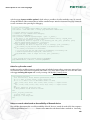
An example of a simple command is:
log("Hello, world!")
The log() function is a specific function that writes a message directly to the NETIO4 event log. It can be used for
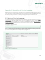
instance to confirm that a given action has been executed or to get other information. In the image shown below,
you can see a message that has been successfully written by a triggered rule.
Figure 23. output of the log() function
38
Description of the Lua language
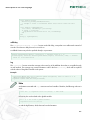
The log() function also supports inserting the contents of a device variable directly into output text:
log("Hello, world!");
-- separate commands with semicolons or spaces
log("Name of event is: ${event.name}");
-- logs the name of the event when it is initiated (choose an appropriate trigger action)
-- a double dash marks the beginning of a comment
A.2. Specifics of the Lua environment in NETIO4
Because of hardware limitations, NETIO4 uses the Lua language without support for decimal numbers. Therefore,
arithmetic only supports whole numbers (unlike standard distributions of the language). All input values are thus
entered as multiples to maintain precision. So for instance the temperature 24.5°C is represented in the code
with the number 2450.
To maintain system integrity, any code entered by the user runs in a closed environment with limited access
to system variables (for instance, device variables that provide access to current values are set as read-only).
Furthermore, running user actions is limited so as to rule out the possibility of getting stuck in an infinite loop
which would preclude normal operation of the system. This limit is set to 32,000 virtual machine instructions each
time a user action is triggered.
Besides this, the Lua environment in NETIO4 provides certain functions to allow cooperation between NETIO4
and other devices.
A.3. Controlling outlets
Switching outlets
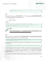
It is possible to control the state of outlets with the SetOut command, which takes two arguments. You can use the
numerical value of the output argument to specify which outlet will be switched. The outlet numbers correspond
to the numbers from the outlets overview in the Outlets menu. You use the value of the boolean value to specify
whether the outlet should be switched on or off.
devices.system.SetOut{output=3, value=false};
-- switches outlet number 3 off
devices.system.SetOut{output=1, value=true};
-- switches outlet number 1 on
Warning
If the automatic Timer function was switched on for the given outlet, switching outlets by means of
user actions turns it off.
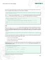
Resetting outlets
It is possible to restart outlets with the ResetOut command, which takes two arguments. Use the first, obligatory,
argument output to specify which outlet will be reset, as with the SetOut command above. Using the second,
39
Description of the Lua language
optional argument resetDelay, you specify how long the outlet restart delay will be (the time from when it is
switched off to when it is switched back on again).
devices.system.ResetOut{output=4, resetDelay=10};
-- restarts outlet number 4 with a delay of 10 seconds
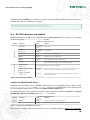
A.4. NETIO4 device variables
NETIO4 internal device variables are accessible through the devices.system object. For instance, you can get the
CPU load through the devices.system.averageLoad variable.
NETIO4 device variables within actions
availability
variable name
contents
description
output1_state
takes the values
on/off/starting/
resetting
State of outlet 1.
for N from 1 to 4
takes the values
on/off/starting/
resetting
State of outlet N.
sessionCount
number
Number of users currently logged in.
freeSpace
disc space in
megabytes
Total disc space on internal flash memory.
totalSpace
disc space in
megabytes
Total available disc space on internal flash memory.
averageLoad
number
Represents the average value of the CPU system load in the last 5 minutes, multiplied
by 100. Smaller is better; bigger is a sign of performance problems.
Only for model NETIO4 All
All NETIO4 models
outputN_state
outputN_consumption
for N from 1 to 4
outputN_cumulatedConsumption
for N from 1 to 4
outputN_consumptionStart
for N from 1 to 4
value in Watts (W) Actual power consumption of outlet N.
value in Watthours (Wh)
Actual cumulated power consumption of outlet N since measuring started.
date and time
Date and time when the measuring of the cumulative power consumption has been
started on the given outlet.
Table 1. Internal device variables
Variables for added Bluetooth devices
If NETIO4 is paired with BT devices, availability of these devices can be detected through a global variable
devices.<sensorName>.connected, where <sensorName> is the name of added BT device. This variable can be
used for example to trigger actions in response to System variables updated event.
To determine the name of the specific BT device that triggered the event created for Any device with Device
disconnected or Device reconnected triggers, use self.name variable.
Variables for added Bluetooth devices
NETIO4
All with
paired
BT device
availability
variable name
contents
description
connected
boolean value
true/false
State (connected/disconnected) of added BT device.
name
text string
Name of BT device which eg. triggers an action.
Table 2. Variables for added Bluetooth devices
These variables and theirs values can be later used in code, see complex example in Section A.10, “Examples”.
40
Description of the Lua language
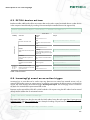
A.5. NETIO4 device actions
Besides variables, NETIO4 also offers some actions that can be used to control connected devices or other devices
in the computer network directly by invoking CGI commands (the controlled device must support CGI).
devices.system.SetOut{output=1, value=false}; -- switches off output no. 1
Device actions
availability
action name
argument
example
output
SetOut
Controls the state of the outlet.
outlet number from 1 to 4
value
devices.system.SetOut{output=1, value=true};
true/false; activates/deactivates the
outlet
All NETIO4 models
output
ResetOut
Restart of the outlet and the powered
device.
outlet number from 1 to 4
resetDelay
devices.system.ResetOut{value=1, resetDelay=10};
outlet restart delay in seconds. If not
specified, the settings value of the given
outlet is used.
CustomCGI
url
Sends an HTTP GET request to the
given URL.
URL to which the command should be
sent
devices.system.CustomCGI{url="http://192.168.0.1/
cgi-bin/foo.cgi"};
Reboot
Only for
model
NETIO4
All
Immediate restart of the NETIO4
device.
ResetCumulativeConsumption
Resets the consumption counter of the
given outlet to zero.
without arguments
output
outlet number from 1 to 4
devices.system.Reboot{};
devices.system.ResetCumulativeConsumption{output=1};
Table 3. Device actions
A.6. IncomingCgi event as an action trigger
IncomingCgi is an event that can be used to input any data into user actions from external sources, such as
cameras, UPS backup sources or various sensors. In order for a user action to be able to react to a received CGI
request, this action must be stored with the trigger Incoming CGI request. The IncomingCgi event is invoked on
the basis of a received HTTP request entered with a URL.
Requests can be sent with the HTTP GET or POST methods. CGI requests using the GET method can be entered
directly into the address bar of an Internet browser:
http://192.168.0.1/event?foo=bar&baz=qux
The same CGI request can also be sent with the POST method using the tools wget (http://www.gnu.org/
software/wget/), curl (http://curl.haxx.se/), etc. Example of sending a request from the command line of a client
PC with the curl tool:
> curl --data "foo=bar&baz=qux" http://192.168.0.1/event
41
Description of the Lua language
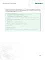
where 192.168.0.1 is the NETIO4 device's address. The following Lua code processes data sent with the GET
or POST methods:
local output = "Incoming CGI request: ";
for key,value in pairs(event.args) do
output = output .. " (" .. key .. " = " .. value .. ")";
end
logf("%s", output);
and writes the following message to the system events log:
Incoming CGI request: (foo = bar) (baz = qux)
It is possible to process values obtained in this way further; see the complex example in section Section A.10,
“Examples”.
A.7. Other action triggers
NETIO4 also offers other action triggers used for automating tasks and interacting with the environment. When
creating user actions, select an appropriate trigger to activate your action. The usage is similar to that of the
Incoming CGI request trigger described in section Section A.6, “IncomingCgi event as an action trigger”.
If you are using NETIO4 All model with the Bluetooth 4.0 LE support, please select desired device first and then
its action trigger. Available devices are - NETIO, paired BT device or Any device (for an actions triggered by
more than one BT device).
NETIO4 device action triggers
Only for model
NETIO4 All
All
NETIO4
models
availability
name of trigger
name of internal
event
description
System started up
SystemStarted
The trigger is activated when the NETIO4 device starts.
State of digital output
changed
DoStateChanged
The trigger is activated when the state of an output (outlet) changes.
Schedule has started or
ScheduleStartStop
stopped.
The trigger is activated when an active schedule is started or stopped.
System variables
updated
Input_updated
The trigger is activated when the system variables are updated, which occurs every 10 seconds;
appropriate for repeated actions.
Incoming CGI request
IncomingCgi
The trigger is activated when a CGI request arrives.
Device disconnected
DeviceDisconnect
The trigger is activated when the paired BT device is out of range.
Device reconnected
DeviceReconnect
The trigger is activated when the paired BT device is reconnected.
Table 4. Action triggers
A.8. Special variables
Special variables within actions
name
devices
description
read-only table of devices and their variables; described above
42
Description of the Lua language
Special variables within actions
name
description
A table filled with the values of the event just handled on the basis of the selection action trigger; contains the following entries:
event
• device – name of the device that invoked the event (e.g., system for NETIO4)
• name - name of the event (e.g., IncomingCgi)
• args – table of the arguments of the events; depends on the event.
Table 5. Special variables within action
It is possible to access individual entries in the event.args table of arguments by extending this variable with the
name of the desired argument. This is an alternative to the example above that does not use the for and pairs
commands to traverse the entire event.args table. When the Incoming CGI request trigger is used, the following
example writes the value "bar" of the argument with the name foo from the incoming CGI to the system log:
log("${event.args.foo}");
-- CGI in the form http://192.168.0.1/event?foo=bar writes the value "bar" of the argument
foo into the log.
A.9. Functions and libraries
The standard assert, error, ipairs, next, pairs, pcall, select, tonumber, tostring, toboolean, type and unpack Lua
language functions can be used for programming actions. Only the os.date, os.difftime and os.time functions
are available from the os library. All functions from the string and table libraries are also available.
It is also possible to use Lua language functions that are specific to NETIO4:
delay
The delay(seconds, callback) function invokes the callback function after the given number of seconds. The
delay function itself executed immediately, and the callback function runs independently of the main code.
Example:
-- we create a local callback function local function
delayedDate()
log("date extraction delayed");
end
-- we time the function
delay(5, delayedDate);
log("delayed date extraction timed"); -- this message appears immediately
Note
Errors that arise in processing delayed functions are not standardly logged anywhere. If necessary,
this can be circumvented with the pcall() function:
43
Description of the Lua language
local function wrong()
devices.non_existing.SetLED{enabled=0}
-- attempt to access a non-existent device and/or action causes the error
end
local function logWrongErrors()
local result, errorMessage = pcall(wrong)
if result == false then
logf("Function failed with error: %s", errorMessage)
end
end
delay(1, logWrongErrors)
milliDelay
The milliDelay(milliseconds, callback) function works like delay, except that it uses milliseconds instead of
seconds. The minimum delay that can be set is 50 ms.
A callback function may also be specified directly in a parameter:
devices.system.SetOut{output=1, value=true}; -- switches outlet no. 1 on
milliDelay(500, function() devices.system.SetOut{output=2, value=false}; end); -- switches
outlet no. 2 off after 500 ms
log
The log(message) function writes the message to the event log of the NETIO4 device that is accessible through
its web interface. The message may contain substitution code in the form ${variable}, which will be replaced
with the values of the global variables in the system.
Example:
log("Current NETIO4 CPU load is ${devices.system.averageLoad}; state of outlet no. 4 is
${devices.system.output4_state}")
log("Event ${event.name} has been processed")
Note
A substitution executed with log() cannot access local variables. Therefore, the following code won't
work:
local foo = 1; log("value of foo is ${foo}"); -- won't work
Of course, this can be solved with a global variable:
foo = 1; -- foo is now a global variable
log("value of foo is ${foo}");
or with the logf function, which does not have this limitation:
44
Description of the Lua language
local foo = 1;
logf("value of foo is %s", foo);
logf
The logf(messageFormat, ...) function works like log(), but messageFormat is a string containing substitute
codes which are replaced by other parameters of the logf() function, which may also include functions. The
most important parameters for specifying the format are:
•
%s
– output as a string
•
%d
– output as a number
Examples:
logf("Time on device: %s, event: %s", os.date("%H:%M:%S"), event.name);
-- writes the local time on the device and event name for automatically executed actions
logf("UNIX time on device: %d, number of users logged in: %d", os.time(),
devices.system.sessionCount);
-- writes the time in UNIX form and number of users logged in
Note
The exact formatting options that log() accepts are identical to those of the string.format Lua function
(http://www.lua.org/manual/5.1/manual.html#pdf-string.format) and very similar to those of the
printf() function used in the C language.
mail
The mail(to, subject, text) function sends an email with the given text to the recipient entered. The subject
and text of the email use the same ${variable} code expansion as the log() function. Under the default setting,
an email with a particular subject is sent at most once every 5 minutes.
mail("[email protected]", "Current NETIO4 load", "Current load is
${devices.system.averageLoad}")
By changing the subject of the email, it is possible to ensure that sending occurs at most once per minute under
the default setting.
mail("[email protected]", "Current NETIO4 load is ${devices.system.averageLoad}", "Further
information");
The maximum frequency at which messages are sent by the mail function can be set with two optional parameters:
minIntervalSec and intervalKey. The minIntervalSec parameter makes it possible to set the exact interval at
which messages are sent. The default value is 300 (5 minutes). The intervalKey parameter is used internally to
ascertain whether the same message has already been sent in the past; if the parameter is not set, the default
message subject is used.
These optional parameters allow better control over the intervals for sending emails repeatedly. The following
code sets the minimum interval for repeatedly sending messages to 30 minutes and also sets a particular interval
45
Description of the Lua language
key in such a way that all messages sent with this code are assigned to the same category for the purposes of the
limit on repeatedly sending messages, even if their subjects are different.
mail("[email protected]", "An event with name ${event.name} occurred", "Some event is coming",
30*60, 'some-event-coming');
The mail() function returns a boolean value (true or false) that designates whether the message was transmitted
to be sent or was blocked by the filter for limiting the number of messages within a given time period.
local ret = mail("[email protected]", "mail", "hello", 60)
if ret == true then
log("we have tried to send the email")
-- we provide an alert that the email may not actually be sent, even at this moment
-- details on this situation will be logged in the NETIO4 system log
else
log("e-mail was not sent, because that would have been more than once in a minute")
end
ping
The ping(address, timeout, callback) function makes it possible to check the functionality of connections
between the NETIO4 device and another device at the specified address in the computer network. The target
device must support the ICMP protocol. Based on the accessibility of the device, it is then possible to execute
your own action with the callback function. The duration of the validity of the request in seconds is an optional
argument.
ping{address="example.com", timeout=60, callback=function(o) log("duration: " .. o.duration);
end}
As can be seen in the previous example, the callback function can get a table from the ping function after it
executes with the following arguments and their return values:
• success: ping success (true/false)
• duration: ping duration (value in milliseconds)
• errorInfo: error description (text)
With these return values, it is possible to write information about the accessibility of any server or other devices
to the NETIO4 device event log. For the following example, use the action trigger Input state updated (the action
will be executed every 10 s):
-- ping example.com and log the result
local function logPingResult(o)
if o.success then
log("example.com ping OK in time: " .. o.duration)
else
log("example.com ping FAILED: " .. o.errorInfo)
end
end
ping{address="example.com", callback=logPingResult}
After entering and saving the rule, look at the event log.
46
Description of the Lua language
A.10. Examples
Action for processing incoming CGI requests with a change of the states of outlets
The first example shows an action for processing an incoming CGI request that contains a change of the state of
outlets. Save the action with the trigger Incoming CGI request.
The incoming CGI request must be in the form http://netio.ip/event?port=10iu&pass=password. Select the value
1 to switch the outlet on, 0 to switch it off, i to restart it and u or another character to leave the given outlet in the
current state. Pass the selected password as the value of the pass argument.
-- function for parsing port arg value and performing its action
local function portparse(s)
local portnumber = 1;
for c in string.gmatch(s, "%w") do -- accept only alphanumerical chars
if portnumber > 4 then return end; -- break
if c=="0" then
devices.system.SetOut{output=portnumber, value=false}
elseif c=="1" then
devices.system.SetOut{output=portnumber, value=true}
elseif c=="i" then
devices.system.ResetOut{output=portnumber}
else -- do nothing
end
-- debug info (remove comment syntax -- on the line bellow to access debug info)
-- logf("CGI parser: Port %d obtain value %s",portnumber,c);
portnumber = portnumber+1;
end
end
local port=event.args.port;
local pass=event.args.pass;
-- Set here your password. The password will be required in the incoming CGI request for this
action to work.
local accepted_pass="password";
-- Comment out the following block of code if you are using more than one CGI-triggered
action.
if (not port) or (not pass) then
log("CGI parser: PORT and/or PASS argument missing, please check your CGI command. Use
following syntax for the control CGI http(s)://netio.ip/event?port=10iu&pass=password where
accepting arguments for port 1 to 4 are: 0...off, 1...on, i...interrupt (reset), any other
char for port skip (unused)");
do return end; -- break (end of action)
end
if (pass==accepted_pass) then portparse(port)
else log("CGI parser: Wrong password")
end
Action for controlling an outlet on the basis of the accessibility of another device in the network
The following example uses the internal ping function to confirm the accessibility of a device in the network and
activates the desired output (outlet) based on it accessibility. For instance, the action can be used to automatically
switch a peripheral device (printer, monitor) of a computer on after the computer is switched on. Save the action
47
Description of the Lua language
with the trigger System variables updated, which makes it possible to check accessibility every 10 seconds.
Change the address of the monitored device and the controlled output. We also recommend using logf commands
to write comments to the system log for debugging.
-- local user variables
local port = 4 -- Change output number of controlled port here
local device = "192.168.0.100" -- Change ping destination address here
-- callback function for ping function
-- comment out logf commands after debugging
local function pingAndRun(o)
local portState = devices.system["output" ..port.. "_state"];
-- two dots ".." for concatenation of the system variable name eg. output4_state
if o.success and (portState == "off") then
logf("PING OK, state of output %d is %s, Enabling port %d", port, portState, port);
devices.system.SetOut{output=port, value=true};
elseif o.success and (portState ~= "off") then
logf("PING OK, but state of output %d is %s, Do nothing", port, portState);
-- do nothing if ping success and portState is different than "off"
else
-- do nothing if the device is unreachable
-- or you can turn off the same output by uncommenting of following line
-- devices.system.SetOut{output=port, value=false};
logf("PING FAIL, state of output %d is %s", port, portState);
end
end
-- main program with the callback function pingAndRun
ping{address=device, timeout=5, callback=pingAndRun}
Action for cyclic outlet control
Another example uses delay function to switching states of individual outputs after a certain time. Action still uses
local function cycler which receives argument with number - how many action repeats we want. Save this action
with trigger Incoming CGI request and run it by incoming CGI like http://netio.ip/event.
local function cycler(n)
local function sw(z, state) devices.system.SetOut{output=z, value=state} end
if n <= 0 then _G.cycler_active = false; return end
if n % 2 == 1 then -- if n is odd number (modulo is used)
sw(1, true); sw(2, true); sw(3, false); sw(4, false); -- output actions
else
sw(1, false); sw(2, false); sw(3, true); sw(4, true); -- output actions
end
delay(10, function() cycler(n-1) end)
-- delay between on/off states in seconds
end
if not _G.cycler_active then
_G.cycler_active = true
cycler(5) -- how many times
end
Actions to control outlets based on the availability of Bluetooth devices
This example demonstrates the use of the availability of the BT device to control the outlet. If BT device appears
within range NETIO4 local returnState function returns true value and selected outlet is switched on. Conversely,
48
Description of the Lua language
if the BT device disappears from the range NETIO4, returnState function returns false value and the outlet is
switcheds off. Action requires the BT device called sensorboard (change as needed) added and paired. Trigger
set to System variables updated and save this action.
local function returnState()
-- stores actual connection state of the BT device named "sensorboard"
local actState=devices.sensorboard.connected;
if prevState == nil then prevState = false; end;
-- logf("actState=%s", tostring(actState)); -- debug only
-- logf("prevState=%s", tostring(prevState)); -- debug only
if actState == true and prevState == false then -- actual state connected, previous state
unreachable
retState = true; -- output should be ON
elseif actState == false and prevState == true then -- actual state unreachable, previous
state connected
retState = false; -- output should be OFF
else
retState = nil; -- both states are still the same
end
prevState = actState; -- stores actual state as previous
-- logf("retState=%s", tostring(retState)); -- debug only
return retState;
end
-- Main program
local state = returnState()
if state ~= nil then
devices.system.SetOut{output=1, value=state}; --change number of controlled port here
end
49
Conclusion
The manufacturer bears no responsibility for any technical or printing errors and reserves the right to make any
changes in the product and in this user manual without prior notice. Any such changes will be announced via
the manufacturer's website www.koukaam.se.
The manufacturer does not provide warranties of any kind whatsoever with regard to any information given in
this user manual or any derived warranties regarding product saleability or fitness for a specific purpose.
In particular, the manufacturer does not provide any warranties for defects caused by incorrect use of the product,
failure to abide by the instructions and recommendations stated in the user manual and for any defects caused
by unprofessional activities of third parties outside the manufacturer's authorized service shop.
We believe that you will be satisfied with our product. In case of any questions or comments relating to the
functionality of the NETIO product, please do not hesitate to contact us.
The company KOUKAAM a.s. represents that all products, software and other third party components used in this
equipment were used by the company KOUKAAM a.s. on the basis of the relevant consent and pursuant to licence
agreements between the company KOUKAAM a.s. and third parties. The company KOUKAAM a.s. reserves the
right to change those licence terms and conditions, as the case may be, and such changes will be published in
the updated version of a manual available on the website of the company KOUKAAM a.s. - www.koukaam.se
The KOUKAAM Team
KOUKAAM a.s.
Türkova 2319/5b
Prague 4, 149 00
Czech Republic
www.koukaam.se
© 2014 KOUKAAM a.s. All rights reserved.
50
Declaration of Conformity
Bulgarian
Български
Cнастоящето, Koukaam a.s. декларира, че това безжично устройство е в съответствие със съществените
изисквания и другите приложими разпоредби на Директива 1999/5/EC.
Czech Česky
Koukaam a.s. tímto prohlašuje, že tento Radio LAN device je ve shodě se základními požadavky a dalšími
příslušnými ustanoveními směrnice 1999/5/ES.
Danish Dansk
Undertegnede Koukaam a.s. erklærer herved, at følgende udstyr Radio LAN device overholder de væsentlige krav
og øvrige relevante krav i direktiv 1999/5/EF
Dutch
Nederlands
Hierbij verklaart Koukaam a.s. dat het toestel Radio LAN device in overeenstemming is met de essentiële eisen en
de andere relevante bepalingen van richtlijn 1999/5/EG Bij deze Koukaam a.s. dat deze Radio LAN device voldoet
aan de essentiële eisen en aan de overige relevante bepalingen van Richtlijn 1999/5/EC.
English
Hereby, Koukaam a.s., declares that this Radio LAN device is in compliance with the essential requirements and
other relevant provisions of Directive 1999/5/EC.
Estonian Eesti
Käesolevaga kinnitab Koukaam a.s. seadme Radio LAN device vastavust direktiivi 1999/5/EÜ põhinõuetele ja
nimetatud direktiivist tulenevatele teistele asjakohastele sätetele.
Finnish Suomi
Valmistaja Koukaam a.s. vakuuttaa täten että Radio LAN device tyyppinen laite on direktiivin 1999/5/EY oleellisten
vaatimusten ja sitä koskevien direktiivin muiden ehtojen mukainen.
French
Français
Par la présente Koukaam a.s. déclare que l'appareil Radio LAN device est conforme aux exigences essentielles et
aux autres dispositions pertinentes de la directive 1999/5/CE
German
Deutsch
Hiermit erklärt Koukaam a.s., dass sich dieser/diese/dieses Radio LAN device in Übereinstimmung mit den
grundlegenden Anforderungen und den anderen relevanten Vorschriften der Richtlinie 1999/5/EG befindet".
(BMWi) Hiermit erklärt Koukaam a.s. die Übereinstimmung des Gerätes Radio LAN device mit den grundlegenden
Anforderungen und den anderen relevanten Festlegungen der Richtlinie 1999/5/EG. (Wien)
Greek
Ελληνική
με την παρουσα Koukaam a.s. δηλωνει οτι radio LAN device συμμορφωνεται προσ τισ ουσιωδεισ απαιτησεισ
και τισ λοιπεσ σχετικεσ διαταξεισ τησ οδηγιασ 1999/5/εκ.
Hungarian
Magyar
Alulírott, Koukaam a.s. nyilatkozom, hogy a Radio LAN device megfelel a vonatkozó alapvetõ követelményeknek
és az 1999/5/EC irányelv egyéb elõírásainak.
Italian Italiano
Con la presente Koukaam a.s. dichiara che questo Radio LAN device è conforme ai requisiti essenziali ed alle
altre disposizioni pertinenti stabilite dalla direttiva 1999/5/CE.
Latvian
Latviski
Ar šo Koukaam a.s. deklarē, ka Radio LAN device atbilst Direktīvas 1999/5/EK būtiskajām prasībām un citiem ar
to saistītajiem noteikumiem.
Lithuanian
Lietuvių
Šiuo Koukaam a.s. deklaruoja, kad šis Radio LAN device atitinka esminius reikalavimus ir kitas 1999/5/EB
Direktyvos nuostatas.
Maltese Malti
Hawnhekk, Koukaam a.s., jiddikjara li dan Radio LAN device jikkonforma mal-ħtiġijiet essenzjali u ma
provvedimenti oħrajn relevanti li hemm fid-Dirrettiva 1999/5/EC.
Polish Polski
Niniejszym Koukaam a.s. oświadcza, że Radio LAN device jest zgodny z zasadniczymi wymogami oraz
pozostałymi stosownymi postanowieniami Dyrektywy 1999/5/EC.
Portuguese
Português
Koukaam a.s. declara que este Radio LAN device está conforme com os requisitos essenciais e outras
disposições da Directiva 1999/5/CE.
Romanian
Romană
Koukaam a.s. declară că acest dispozitiv fără fir respectă cerinţele esenţiale precum şi alte dispoziţii relevante ale
Directivei 1999/5/EC.
Slovak
Slovensky
Koukaam a.s. týmto vyhlasuje, že Radio LAN device spĺňa základné požiadavky a všetky príslušné ustanovenia
Smernice 1999/5/ES.
Slovenian
Slovensko
Koukaam a.s. izjavlja, da je ta radio LAN device v skladu z bistvenimi zahtevami in ostalimi relevantnimi določili
direktive 1999/5/ES.
Spanish
Español
Por medio de la presente Koukaam a.s. declara que el Radio LAN device cumple con los requisitos esenciales y
cualesquiera otras disposiciones aplicables o exigibles de la Directiva 1999/5/CE
Swedish
Svenska
Härmed intygar Koukaam a.s. att denna Radio LAN device står I överensstämmelse med de väsentliga
egenskapskrav och övriga relevanta bestämmelser som framgår av direktiv 1999/5/EG.
Turkish Turk
Koukaam a.s. bu kablosuz cihazın temel gereksinimleri ve 1999/5/EC yonergesindeki ilgili koşulları karşıladığını
beyan eder.
51