1
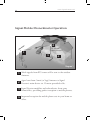
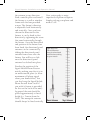
www.signalmaster.net
Signal Mobile Phone Booster
Installation and Operation Manual
Home and Office Indoor Repeater
English
USER’S
MANUAL
Thank you for purchasing Signal Mobile Phone Booster.
Please read these instructions for information about using the product correctly and safely.
Keep the instructions handy for future reference.
Signal Repeater Installation and Operation Manual
2
www.signalmaster.net
3
Table of Content
About this Manual
Saftey Instructions
General Information
Introduction
product
Features
How does it work?
5
5
6
6
6
6
6
Installing Signal Mobile Phone Booster
Antenna Installation
Site Selection
Step 1: Locating the Signal Booster
Step 2: Setup the Signal Booster
Step 3: Aligning the Directinal antenna
Step 4: Finalising Booster Installation
8
8
8
10
11
12
12
Checking the System
Trouble Shooting
Frequently Asked Questions
12
18
20
Appendix A
Outdoor Antenna Installation Guide
21
21
Appendix B
Boat application
24
24
Appendix C
Signalica
25
25
Customer Records
30
Notes
31
Signal Repeater Installation and Operation Manual
4
5
www.signalmaster.net
About this Manual
This manual provides complete instructions for installing and using
Signal Repeater. Be sure to read this User’s Manual before starting
the operation of the Booster and the other peripheral equipment.
Safety Instructions
- Never open the cover.
- When the Booster is unused for a long time, unplug the power
cord from the wall outlet.
- Do not use a damaged power cord that may cause a fire or an
electric shock.
- Do not touch a power cord with wet hand. It may cause an
electric shock.
- This unit is powered by small AC adaptor unit. Turn off the
electricity supply if you have to do any rewiring or making
alterations to wall sockets.
- The equipment should be used only for amplifying mobile
(cellular) phone signals and not for any other purpose.
- Should the unit fail to operate, any repairs should be carried out
by qualified personnel ONLY.
- The RF energy that the unit radiates is very small (max of 5mW)
this level is many times smaller than the RF power radiated by
your mobile phone.
Signal Repeater Installation and Operation Manual
6
General Information
Introduction
Almost all of us have
experienced a dropped call or
“The Mobile phone you have dialed
is outside of the coverage area”
messages on our cell phones.
This phenomenon occurs
because there is inadequate
signal strength from the
cellular towers that provide
network coverage. You see the
base station cellular towers
along roadsides, on top of
communications towers, and
installed on some buildings in
urban areas. Often transmission
to and reception from a cellular
tower is weak because the tower
is such a long way away from
the mobile unit. Other times,
buildings block the cellular
signal or make it patchy. Full
coverage is quite rare, and due
to “poor reception” we experience
interruption of conversations,
voice distortion and dropped
calls.
The Signal Mobile Phone Booster
is the solution to this problem.
Repeaters not only amplify the
weak received signal, but they
also reduce the need for high
level of RF transmission from
your mobile phone, reducing
undesirable radiation exposure
and battery drainage. The Signal
Mobile Phone Booster is ideal for
areas such as offices, apartment
blocks and homes where your
phone is ordinarily unable to get
adequate reception. By boosting
the signal, this device enhances
the signal from your handset,
ensuring a reduction in noise
and call drops, and so better
quality of service.
Product
Signal Mobile Phone Booster is
a very powerful mobile phone
signal amplifier, suitable for
people who have problems
with weak signals within GSM
networks. This system is ideal
for smaller applications in order
to receive a strong signal within
7
offices, underground areas,
factories, hotels or warehouses.
Features
- The small size of the device
and the option of plug and play
enables easy installation.
- The Signal Mobile Phone
Booster can simultaneously
work with multiple GSM
network operators.
- The Signal Mobile Phone
Booster has the capability
of simultaneously repeating
the full band in the same
frequency band.
- The aluminium die-casting
case provides the firm and
stable motions.
- Excellent environmental
resistance.
Automatic limit control: This
function limits the output level
to the fixed one to avoid any
damage to the existing network,
as the output level varies
according to changes in input
signals.
LED Level meter: As the intensity
of the forward signal is displayed
on the LED, it enables the
user to conveniently check the
operating status in use as well
www.signalmaster.net
as tuning and placement of the
antenna during installation.
Automatic shutdown: This function
cuts off signals automatically
when the repeater reaches an
uncontrolled status due to
excessive input signals.
Alarm LED: When any mechanical
error occurs, the alarm lamp
lights up.
How does it work?
Look at the image on the next
page to understand the setup of
the Signal Mobile Phone Booster
kit. The repeater is made up of
two main parts: the directional
panel antenna and the Signal
Mobile Phone Booster unit.
The directional panel antenna
is aligned with the closest cell
phone tower, and collects the
cellular signal. This signal is
then sent via a 15-metre cable to
the Signal Mobile Phone Booster
unit. The amplifier unit boosts
the signal, and then retransmits
it about your home or office
using a monopole broadcast
antenna.
Signal Repeater Installation and Operation Manual
8
Installing Signal
Mobile Phone Booster
Antenna Installation
This is one of the most
important processes in the
repeater installation, as this
phase decides the performance
of the equipment.
The system includes two omnidirectional antennas, one for
indoor use and the other one for
outdoor use. First, find a suitable
place to install the outdoor
antenna, and attach the antenna
bracket. Fix its connector to the
bracket and then attach it. Once
the antenna bracket is fixed with
a connector, bring the coaxial
cable to the place to attach the
repeater body.
Site Selection
The first thing you need to do
before installing your Signal
Mobile Phone Booster is to find
out where you want to install the
repeater. Look at the Diagram 1
for an idea of how the Cellular
Repeater works:
1. The cellular signal is
broadcast to/from the cellular
tower.
2. The directional panel
antenna collects the signal from
the cellular tower.
3. The Signal Mobile Phone
Booster amplifies the signal
and re-broadcasts it about your
home/office.
4. Ideally, the Signal Mobile
Phone Booster Unit and the
monopole broadcast antenna (3
in Diagram 1) should be placed
central to your home/office in
order to maximize coverage. The
directional panel antenna (2 in
Diagram 1) should be outside
your home/office, facing towards
the closest cellular tower
and with as few obstructions
(buildings, cars, trees etc)
directly in front of it as possible
an elevated position often helps
this.
www.signalmaster.net
9
Signal Mobile Phone Booster Operation:
2
1
15 metres
cable provided
3
4
Diagram 1
1
Weak signals from BTS tower will be sent to the outdoor
Antenna.
2
Signal
3
Signal Booster amplifies and rebroadcasts about your
home/office, providing perfect reception to mobile phones.
4
Improved reception for mobile phone sets in your home or
office.
sent from Omni (or Yagi) Antenna to Signal
Booster’s main device via 15 metre provided cable.
Signal Repeater Installation and Operation Manual
More information on the placing of
the directional antenna is provided
below.
Step 1 – Locating
the Signal Booster
The best way to find the best
cellular signal around your
home/office is simply to walk
around with your cell phone on.
You should use a cell phone on
the network/band whose signal
you are trying to improve. The
“Signal Strength” meter on your
10
cell phone will tell you where
the signal is strongest.
Note: The Mobile Phone “Signal
Strength” meter takes up to 30
seconds to update as you move
from location to location, so
make sure to take a nice long
pause in every location you test.
The place you choose should
either be outside, or in the very
least by a window. It should also
be within 15 Metre of where you
want to rebroadcast the cellular
signal (this is the length of the
provided cable).
11
www.signalmaster.net
Step 2 – Set up the
Signal Booster
Once you have established what
part of your home has the best
signal, you will need to set up
the Signal Mobile Phone Booster
as specifies below.
1. Place the panel antenna in
the place with the best signal
and connect it to the 15 Metre
cable.
2. Connect the other end of the
cable to the connector on the
bottom side of the Signal Mobile
Phone Booster Unit.
3. Finally, connect the
monopole broadcast antenna
to the connector on top of the
Signal Mobile Phone Booster.
4. Move the Signal Mobile
Phone Booster unit inside to
where you want the signal to
be rebroadcast. Try to make
sure that the directional panel
antenna and Signal Mobile
Phone Booster unit are as
far away from each other as
possible, and separated by a wall
if at all possible.
Above mentioned point is
very important because it
provides isolation between
the directional panel antenna
and the monopole broadcast
antenna. The two antennas need
to be isolated from one another
in order to prevent feedback/
oscillation (this occurs when the
directional input antenna picks
up the signal broadcast by the
broadcast antenna). In order to
prevent feedback/oscillation, the
directional panel antenna and
the monopole antenna should be
distanced from each other, and
the directional panel antenna
should always be facing away
from the monopole broadcast
antenna. It is not vital to have a
wall between the panel antenna
and the amplifier unit, but if
possible, it can help reduce the
changes of oscillation/feedback
occurring.
5. Make sure that the panel
antenna is facing in a direction
AWAY from the Signal Mobile
Phone Booster unit.
6. Plug the DC adapter
provided with the Signal Mobile
Signal Repeater Installation and Operation Manual
Phone Booster package into an
electrical socket, and connect
the other end to the “DC in” plug
on the bottom of the amplifier
unit.
12
a medium (up to 5 lights on)
signal – the “low” signal level is
just background signal noise and
will not improve your cellular
signal.
7. The unit’s power “on” light
should turn green, signaling that
the unit is operating.
STEP 3 - Aligning the
Directional Antenna
Now go back to the directional
panel antenna. As you turn the
panel antenna, the indicator
lights will show the strength of
the signal from the direction it is
facing. Have someone else stand
by the indicator lights, and tell
you which direction provides the
strongest signal (highest light
level). Make sure never to turn
the directional antenna so that
it is facing the direction of the
Signal Mobile Phone Booster unit
(see image below). Depending on
the signal quality in your area,
you will be able to get a low,
medium, or high strength signal.
In order for the Signal Mobile
Phone Booster to work properly,
you will need to find at least
STEP 4 - Finalizing
the Signal Booster
Installation
To establish the repeater body,
first attach the repeater’s
mounting bracket to the wall,
and firmly fix the repeater to the
bracket.
[Caution] As this bracket does not
have a locking device, it does not
provide a preventive measure
against burglary.
It is recommended that the
repeater body be installed in a
place with a shorter cable, so as
to, have complete visual control
from the indoor. Since a longer
antenna cable has heavier loss,
less than 40m of the length is
desirable (if 3D-FB). However,
if there exist no alternative and
long cable must be used, make
sure a low-loss cable is used.
www.signalmaster.net
13
locked into each other.
Screw
No. 1
No. 3
No. 6
If not using the specified screws,
you must consider carefully
the thickness and the height of
screw head, Because there exists
the possibility that the rear of
the repeater body may come into
contact with the screws.
No. 5
Use an AC adaptor to supply
power for the repeater. As the
repeater AC power supply
adaptor is designed for 100V
~ 270V free voltages, it is not
necessary to pay attention to the
voltage, however it is safer to
check it.
No. 4
Screw
No. 2
Bracket
Fixing the bracket requires at
least 4 screws.
For balance, first tighten up
screw No.1, and then screw No.
2 next, slightly hang the repeater
to move it left or right for proper
balance, finally tighten the
remaining screws No. 3, 4, 5 and
6. Balancing is now completed.
Hang the repeater on the bracket
so that four slots on the rear of
repeater and four wings of the
attached bracket are correctly
Connect the antenna cable and
the power supply to the repeater.
Before connecting the power
supply, always make sure that
the power switch on the bottom
of repeater is set to OFF. Turn
the power switch to ON in order
to operate the equipment. When
powering on the equipment, the
LED attached on the front lights
up; to begin with, PWR (Power
LED) LED should light up.
Once you have found the
direction with the best signal,
you will need to fix the panel
antenna in that direction. The
panel antenna comes with
fixtures that allow you to fix
Signal Repeater Installation and Operation Manual
the antenna in any direction.
Find a suitable place and install
the fixture to a wall or window
frame with the four provided
screws. The fixture’s direction
is adjustable both horizontally
and vertically. Once you have
chosen the direction for the
fixture, it can be fixed in that
direction by tightening the screw
that runs horizontally through
the fixture. Once the directional
and position of the fixture have
been fixed, the directional panel
antenna can be connected by
sliding the directional panel
antenna from above onto the
fixture. You will hear a click
once the directional panel
antenna has locked into place.
Finalize the position of the
Signal Mobile Phone Booster
unit by making sure that it is in
an unobstructed place (to allow
maximum cell phone signal
about your home/office). You
can also hang the Signal Mobile
Phone Booster from a wall if
you wish (a fixture is provided
for this on the back of the unit).
In general the unit should be
placed approximately at headheight (i.e. 2 metre from the
floor). The monopole antenna
should always be fixed vertically.
14
Now you’re ready to enjoy
improved cell phone reception.
Simply pick up your phone and
make a call!
Tip: Yagi and
Omni antennas
may be mixed and
matched according
to your needs.
Omni Antenna
Yagi Antenna
www.signalmaster.net
15
Checking the System
Power Supply &
Status Check With
Operating Status Check Mobile Phone
Checking the Input Level: Once the
repeater receives signals from a
base station, the LED level meter
indicating the reception level
lights up one by one from the
leftmost, displaying the level of
signals received from the station. If the intensity of signals
corresponds to -80 dBm, just
one LED lights up and then,
increases by 5 dB each time.
Up to five LEDs can light up,
which indicates that more than
-60 dBm of input signals are
received. In addition, as the gain
is set to 70 dB and the output
power to 10 dBm or less by the
ALC (Automatic limit control),
the out-of-range input signals are
automatically controlled to be
output regularly all the time.
Checking the operating status
with a cellular phone is one of
the simplest methods. First,
confirm the indoor levels with
repeater set to power-off, next,
compare the levels under poweron. It is more effective to confirm
them farthest from the repeater.
Also, it is important to evenly
confirm phones from several
service providers within the
frequency band. At this time,
in favorable conditions, levels
should indicate the highest possible signal level meter of the
cellular phone.
Signal Repeater Installation and Operation Manual
16
Using measuring
instrument
If more indoor
coverage is desired.
As a method to perform more
detailed measurements, this
enables you to determine how
signal levels can be received
indoor, by means of Spectrum
analyzer or Field strength meter.
As options of this equipment,
the outdoor Yagi antenna and
the indoor Patch antenna may be
provided. They can expand the
coverage through the superior
gain, compared with conventional antennas.
If using the outdoor Yagi antenna, it enables a more dynamic
exchange of signals from the
base station, it is capable of
outputting fully at 10 dBm, the
maximum output of the repeater.
And, if using the indoor patch
antenna, it enables signals to be
transmitted to the cellular phone
more effectively than the existing
omni-antenna, it is even possible to call far away from the
repeater.
Spectrum analyzer
However, since they have unique
directivity, adjustment of the
direction is mandatory. In the
case of the outdoor antenna, use
an instrument or the LED level
meter mounted on the repeater
to set it towards the direction
where best intensity is sensed.
Provided that the situation corresponds to warning it must point
17
to the direction of the provider
whose base station is located
farthest.
[Warnings]
This repeater is designed to reply
simultaneously to broadband
frequencies, as a broadband repeater. The following situations
require careful installation:
1) Under more than two
service providers the existing
frequency band of the repeater
to be installed, if a certain base
station is located within tens of
meters, while the other stations
are at several kilometers, signals
from the nearby station are
much more dominant. So, ALC
operates automatically and in
this situation, the attenuator
operates at up to 31 dB. For
this reason, as signals from a
long-distance station decrease
the gain of the repeater, the
maximum gain of 70 dB is
unavailable, hence; it may fail to
relay. Ergo, in such a case, use
only a directional antenna (Yagi
antenna, etc.) to install it in the
opposite direction to the nearby
station, in order to minimize
the signals exchanged with the
station.
www.signalmaster.net
2) Since this equipment
performs high-gain
amplification, If the outdoor
antenna is close to the indoor
one, Or the two antennas are
adjacent, the RF signal may be
feed-backed and abnormal selfoscillation may occur, which
may cause serious damage to
the cellular phone, even worse,
to the base station. Therefore,
be very careful. The predictors
which help prevent such
problems, include the following:
the five LEDs on the LED level
meter light up fully or the ALM
(Alarm) LED lights up, although
the cellular phone receives weak
signals during installation of
the repeater. The most reliable
method is to measure and check
the condition with spectrum
analyzer.
3) Never install the antenna in
the places where the risk of a
fire is highly, the equipment may
come in to contact with water
due to leakage, or where the
mobile blocker is installed.
Signal Repeater Installation and Operation Manual
18
Trouble Shooting
Before calling for technical services, please check below items,If there is a problem
with the system.
Problem
Solution
The PWR LED in
the front of the
equipment doesn’t
light up, although
the equipment is
completely installed
and switched ON.
1) Check whether the power is normally supplied in the
AC Power source outlet.
The signal level is
not displayed on
the cellular phone,
although the PWR
LED lights up
normally.
1) Check whether the PWR LED in the front of the
equipment lights up.
2) Check whether the DC Jack is correctly connected.
3) Check whether DC 9 V is output from the AC
Adapter; if an error is found, replace it.
The PWR LED lights 1) Check whether the outdoor antenna is correctly
connected.
up normally, but
the LED level meter
doesn’t light up at all. 2) Check whether the antenna cable (coaxial cable) or
the connector is correctly connected. When, signals
are very weakly received from the base station, normal
reception is unavailable even outdoor (where the
outdoor antenna is installed), check it with the cellular
phone or measuring instrument. If the signals are poor,
adjust the position of the antenna. Nevertheless if they
are poor, use the Yagi antenna to increase the gain of the
antenna.
3) Check whether the frequency band indicated in
the electrical features of the used repeater meet the
frequency specification supported by the service
provider in the real environment. As GSM900 or 800
MHz repeaters use the full band, an additional check
is unnecessary. However, for GSM1800 or GSM1900,
their frequencies are divided into two or three types, so
always check it.
www.signalmaster.net
19
Problem
Solution
The ALM LED lights
up during operation.
1) When the signals are very strongly received from
the base station, adjusting the ALC in the repeater is
unavailable, hence, change the installed place of the
indoor antenna to make receiving signals a little distant.
2) When due to the short distance between the outdoor
and indoor antenna, self-oscillation occurs, change the
installed places of the antennas in order to maximize the
distance between them.
3) When a base station or a repeater of the currently
in-service communication provider or another service
provider is newly established in the proximity, change
the position of the outdoor antenna to reinstall the
antenna in the place where the signals from the newlyestablished base station are received the most weakly.
The “ALM” Light Is
Constantly Lighted
This means that the input signal strength is too strong,
causing what is known as “signal saturation” – this
reduces to effectiveness of the repeater unit. You should
change the direction of the antenna to a direction from
which the signal is weaker, such that the “ALM” light is
not constantly on.
The “ALM” Light
Turns On
This “alarm” light signals oscillation due to signal
feedback. When the alarm light is on, the unit is no
longer operation – it will automatically reset after
one minute or you can reset the unit manually by
disconnecting and reconnecting the power cable. In
order to prevent the alarm light from turning on, you
need to ensure the isolation of the directional antenna
from the monopole broadcast antenna. To do this, make
sure that the directional antenna is facing away from the
repeater unit and is sufficiently far away. Also, you can
improve isolation by installing the repeater with a wall
between the directional antenna and the repeater unit.
See the “Step 2” of the installation procedure above for
more information.
Signal Repeater Installation and Operation Manual
Frequently
Asked Questions:
Do I need to know where the cell
tower using this system?
Not with the standard supplied
omni directional with antenna.
However, if you purchase the
higher gain antennas, the Yagi
or the Panel, then all you have
to do is rotate them on the pole
until the signal strength is at a
maximum inside the building.
Do I need to connect my cell phone
directly to the repeater with a cable
or adapter?
No. The system is completely
wireless.
I can make a call outside my home,
but can’t inside. Will the MGR-0910
help?
The Signal Mobile Phone Booster
system is designed especially for
this situation.
Do I need to know where the cell
tower (BTS) is to point the exterior
Yagi Antenna?
There is no need to know this
20
information. All you have to
do is slowly rotate the Yagi (or
Panel) antenna until the signal
on the inside of the building
comes up to a maximum. The
direction that the antenna points
in is the direction of the tower.
Is it possible to purchase and use an
extension cable?
Extension cables should only
be used if the signal strength
outside your home/office (or
wherever the directional panel
antenna is installed) is quite
strong (3 or more bars on your
cell phone without the repeater
installed). If the signal strength
is relatively weak, the use of an
extension cable will decrease
the signal further, and thereby
decrease the coverage area of the
repeater system.
Visit our website or call us for
information about purchasing an
extension cable for your repeater.
Using third-party cables with
our repeaters will void the
product warranty.
Will the repeater improve signal on
more than one level of my home or
office?
Due to the nature of the omni
directional antenna used with
21
our repeater (and with almost all
other commercial repeaters) the
improvement in signal coverage
is largely limited to the level on
which the repeater is installed
(though some improvement will
be seen on adjacent levels). For
this reason, you should install
the Signal Mobile Phone Booster
unit on the same level where you
will be using your cell phone.
Is the repeater system waterproof?
Can it be installed outside?
The directional panel antenna is
waterproof, and can be installed
outside. However the Signal
Mobile Phone Booster unit is
not waterproof and must be
installed indoors in a controlled
temperature environment
(maximum ambient temperature
for correct operation is 40°C or
104°F) .
Does the repeater support multiple
network carriers?
The repeater will amplify the
signal on all carriers operating
on the frequency band of the
repeater in your area (either 800
or 1900 MHz, depending on the
model you have purchased).
www.signalmaster.net
APPENDIX A
Outdoor Antenna
Installation Guide
The most important thing for
the best performance of the
cellular phone Repeater is
antenna installation. Checking
the following points is
recommended when you install
the antenna.
1. If base transmission station
BTS Tower can be seen, install
the antenna toward it. If there
is no BTS around the location,
install antenna in the highest
place.
2. The antenna element should
be aimed in vertical direction
without any obstacles in 50
cm around. Any obstacle
may reduce the radiation
efficiency of the antenna and
cause problems in signal
transmission.
3. Avoid installation of the
antenna near power source.
Signal Repeater Installation and Operation Manual
Especially, you should give
enough distance from the high
voltage power.
4. If you can use spectrum
analyzer, it is the best way to
locate the strong signal point
and to install your antenna
there.
5. If the base station is very near,
you must use attenuator to
adjust the signals or install the
antenna on the opposite side
22
of the building to weaken the
strong signal coming directly
from the base station.
6. When you finish installation
of the antenna, you should do
the waterproof treatment all
around the antenna connector
to prevent the rain sneak. If
Repeater gets wet with water
through cable, the Repeater
and cable may have critical
damages.
MGR-0910
UL 890 ~ 915MHz,
DL 925 ~ 960MHz
Pass Bandwidth
25MHz
Output Power
30dBm max
Max. Input Power -25dBm
Gain
UL 70dB, DL 70dB
Ripple
<4dB
N/F
<7dB
IMD
In-band: -17dBm
Out-band: -36dBm
VSWR
<1:1.5
Power
DC 9V - 2.3A
Operating Temp. -20°C ~ 70°C
Dimension
158W x 237H 40.7D mm
Frequency
Specifications
UL 890 ~ 915MHz,
DL 925 ~ 960MHz
25MHz
l0dBm max
-25dBm
UL 55dB, DL 65dB
<4dB
<7dB
In-band: -17dBm,
Out-band: -36dBm
<1:1.5
DC 5V - 2.3A
-20°C ~ 70°C
130W x 200H 25D mm
Mr. Brown
UL 890 ~ 915MHz,
DL 925 ~ 960MHz
25MHz
l0dBm max
-25dBm
UL 20dB, DL 40dB
<4dB
<7dB
In-band: -17dBm,
Out-band: -36dBm
<1:1.5
DC 12V - 2.3A
-20°C ~ 70°C
82W x 97H x 28D mm
MBD-209
23
www.signalmaster.net
Signal Repeater Installation and Operation Manual
24
APPENDIX B
Boat Application
1) 60dB Normal Application
We recommend the installation
as shown in the opposite
pictures. The position of the
antenna is very important.
Considering the specific
environment of the moving boat,
you should use omni-directional
antenna. Also, very high gain
antenna (over 12dBi) and low
loss cable are suggested. And the
antenna should be “the higher,
the better”.
High Gain Antenna
12 dBi
MBD-209
2) 70dB High Gain Solution
If you need to obtain more gain,
we suggest you to use two MBD209 array in series. Then, the
total gain will be 80dB with
maximum power. You can use
this method only when the cable
length between one MBD-209
and another MBD-209 is more
than 20 meters distance.
We suggest you to install one
MBD-209 just below the outdoor
antenna, and another one should
be installed near indoor antenna.
High Gain Antenna
12 dBi
MBD-209
MBD-209
Patch Antenna
7 dBi
25
APPENDIX C
SIGNALICA
Below glossary is provided to help you
understanding the technical terms in
Antenna industry.
2.4 GHz Antenna A 2.4 GHz antenna is one
that is designed to operate in the 2.4
GHz unlicensed band.
802.11 Antenna An 802.11 antenna
operates in either the 2.4 GHz or 4.95.9 GHz unlicensed bands.
Active Antenna An active antenna includes
electronics to optimize the performance
of the antenna.
Adcock Antenna An Adcock antenna is
made up of four antenna elements
(each of which is usually a monopole
antenna), each of which is mounted at a
corner of a square.
AM Antenna AM antenna is a colloquial
term for an MF (medium wave) antenna
used to receive AM broadcast stations.
Amateur Radio Antenna An amateur
radio antenna is antenna used for
transmitting and receiving by an
amateur radio operator.
Antenna Repeater An antenna Repeater is
an Repeater that is used to boost either
the transmitted power or the received
power from an antenna.
Antenna Booster An antenna connector
is often used at the antenna port of a
radio and at the junction of the antenna
and antenna feeder.
www.signalmaster.net
Antenna Cable Antenna cable is another
term for the antenna feeder.
Antenna Connector An antenna connector
is often used at the antenna port of a
radio and at the junction of the antenna
and antenna feeder.
Antenna Design Antenna design is the
process of designing an antenna.
Antenna Diversity Antenna diversity refers
to antenna systems that involve the use
of two or more receive antennas such
that the output of the receiver is the
best available.
Antenna Efficiency Antenna efficiency is
the ratio of the power radiated in the
antenna’s radiation resistance to that
radiated in its total resistance.
Antenna Feeder A balanced antenna
should be connected to a balanced
antenna feeder and an unbalanced
antenna to an unbalanced antenna
feeder.
Antenna Gain The antenna gain is
normally defined as the increase in
power radiated by an antenna in a
particular direction compared to a
reference dipole, or a reference isotropic
radiator.
Antenna Length Antenna length usually
refers to the length of the active element
of an antenna.
Antenna Masts Antenna masts provide
the structural support for an elevated
antenna.
Antenna Mount An antenna mount is
the hardware that is used to secure
antennas to antenna masts.
Antenna Radiation Pattern The radiation
Signal Repeater Installation and Operation Manual
pattern of an antenna is usually shown
as a polar diagram.
Antenna Rotator An antenna rotator is
used to change the orientation of a
directional antenna.
Antenna Software Antenna software is
used to calculate the performance of an
antenna system.
Antenna Switch An antenna switch is
used to switch a single transmitter or
receiver between multiple antennas.
Antenna System An antenna system
includes the antenna and all the
associated components required for the
antenna to operate.
26
Balun (Balanced-to-unbalanced network)
When an unbalanced transmission line
is connected to a balanced antenna
(coaxial line to a dipole, for example),
extraneous currents run along the outer
surface of the transmission line.
Base Station Antenna A base station
antenna is the antenna at the base
station of cellular mobile phone
network.
Bluetooth Antenna A Bluetooth antenna is
usually a monopole antenna or a dipole
antenna.
Car Radio Antenna Car radio antenna is
another term for a auto antenna.
Antenna Theory Antenna theory is
a mathematic description of the
operation of antenna systems.
CB Antenna A CB antenna is an antenna
used for a citizens band radio,
operating in either the VHF band or the
UHF band.
Antenna Topper An antenna topper is a
decorative device that is designed to be
placed on top of an antenna
CDMA Antenna A CDMA antenna is
antenna for a CDMA mobile phone
antenna.
Antenna Tower Antenna tower is another
term for an antenna mast.
Cell Phone Antenna Cell phone antenna
is alternative term for a cellular (or
mobile) phone antenna.
Antenna Tuner An antenna tuner, or
antenna tuning unit, is used to match
the impedance of an antenna to the
characteristic impedance of the antenna
feeder and the output impedance of a
transmitter or input impedance of a
receiver.
Array Antenna An array antenna is made
up of a number of elements, each of
which is either active or passive.
Auto Antenna Auto antenna is another
term for a car radio antenna.
Balanced-to-unbalanced network See Balun.
Cell Phone Antenna Booster A cell phone
antenna booster is a power Repeater
that is used to increase the transmit
power from a cell phone.
Cellular Phone Antenna A cellular phone
antenna is part of every cellular phone,
including GSM, AMPS, CDMA and
TACS.
Corner Reflector The corner-reflector
antenna is predominantly used on lineof-sight radio relay links and consists of
a normal half-wave dipole in front of a
corner reflector which acts as a mirror.
27
Delta Antenna A delta antenna is a
vertical, triangle-shaped antenna that is
used for HF skywave communications.
DF antenna (Direction finding antenna) A DF
antenna (direction finding antenna) is
used to provide a line of bearing to a
transmitter.
Digital Television Antenna A digital
television antenna is designed to
receive digital television signals.
Digital TV Antenna A digital TV antenna is
designed to receive a digital TV signal.
Dipole Antenna A dipole antenna is
formed by splitting the two wires of
a two-wire transmission line, and
bending them back to form a single
straight line. The antenna feed is in the
middle of the dipole antenna, where the
split occurs.
Direction finding antenna See DF antenna.
Directional Antenna A directional antenna
is one that transmits and receives
power preferentially in a particular
direction.
Discone Antenna The discone antenna is
a further development of the groundplane antenna in which a circular disc
is substituted for the monopole, so that
the antenna has a broadband response.
Dish Antenna Dish antenna is another
term for a parabolic antenna.
Flat Panel Antenna A flat panel antenna is
constructed in a panel.
FM Antenna FM antenna is a colloquial
term for a VHF antenna used to receive
FM broadcast stations operating in the
VHF band.
www.signalmaster.net
Folded Dipole Antenna A folded dipole
antenna is constructed by wrapping the
ends of a dipole antenna around and
joining them together.
Fractal Antenna A fractal antenna, also
known as a fractal element antenna,
uses the properties of fractals to
provide small, efficient antennas for a
wide variety of applications.
Gap Antenna Gap antenna is another term
for a slot antenna.
GPS Antenna A GPS antenna is designed
to receive navigation signals broadcast
by GPS satellites.
Grid Antenna A grid antenna is usually
a reflector antenna in which a grid
conductor is used in place of a solid
conductor.
GSM Antenna The purpose of the GSM
antenna is to transmit and receive
signals on the link to the GSM mobile
phone base station.
Ham Radio Antenna A ham radio antenna
is antenna used for transmitting and
receiving by an ham (amateur) radio
operator.
HDTV Antenna An HDTV antenna is
designed to receive HDTV television
signals.
Helical Antenna A helical antenna is
constructed using a helix of wire that is
fed at one end and unconnected at the
other.
HF Antenna (High frequency antenna) An
HF antenna (high frequency antenna)
operates in the HF band, between 3
MHz and 30 MHz.
Horn Antenna A horn antenna couples
Signal Repeater Installation and Operation Manual
energy between free space and a
waveguide.
Indoor Antenna The term indoor antenna
is sometimes used to refer to an indoor
television antenna.
Inverted V Antenna An inverted-V antenna
is a travelling-wave antenna with high
gain.
Log Periodic Antenna A log-periodic
antenna is a broadband self-tuning
antenna.
Long Wire Antenna The long wire antenna
is simply a long piece of wire that is
used as an antenna.
Loop Antenna A loop antenna consists
of a loop of wire, with each end of the
loop connected to one conductor of the
antenna feeder.
Marine Antenna A marine antenna is
usually designed to be mounted on a
boat or ship.
Microstrip Antenna A microstrip antenna
is fabricated in the same way as a
printed circuit board.
Microwave Antenna A microwave antenna
is designed to operate in the microwave
bands.
Mobile Antenna Mobile antennas another
term for a mobile phone antenna.
Mobile Phone Antenna A mobile phone
antenna is part of every mobile phone,
including GSM, CDMA, AMPS and
TACS.
Mobile Phone Antenna Booster A mobile
phone antenna booster is a power
Repeater that is used to increase the
transmit power from a mobile phone.
28
Monopole Antenna A monopole antenna
can be thought of as being one arm of
a dipole antenna, with the other arm
having been removed.
Omnidirectional Antenna An
omnidirectional antenna is one that
transmits and receives power equally in
all directions.
Parabolic Antenna (Paraboloid) A parabolic
antenna surface has the useful property
of being able to convert a diverging
spherical wavefront into a parallel
plane wavefront, thereby producing a
highly focussed or narrow pencil beam.
Patch Antenna A patch antenna radiates
using a number of elements known as
patches.
Phased Array Antenna A phased array
antenna is an array antenna in which
phases shifts can be applied to the
signals received or transmitted from
individual elements in such a way that
the antenna can be electrically steered.
Plasma Antenna A plasma antenna is a
type of reflector antenna in which
the metal conducting surface of a
conventional reflector is replaced by a
plasma.
Radar Antenna A radar antenna is used
as the antenna in a radar system. In a
mono static radar system, a common
antenna is used for transmitting and
receiving.
Reflector Antennas A reflector antenna
is one in which a passive, reflecting
element is used to distort the radiation
pattern away from itself.
Resonant Antennas A resonant antenna
is one that operates by means of a
29
standing wave.
Rhombic Antenna A rhombic antenna
is a travelling wave antenna use for
skywave communications.
Satellite Antenna A satellite antenna is
used as the antenna on a satellite earth
station.
SHF Antenna (Super high frequency antenna)
An SHF antenna (super high frequency
antenna) operates in the SHF band,
between 3 GHz and 30 GHz.
Shortwave Antenna Shortwave antenna is
another term for HF antenna.
Slot Antenna A slot antenna is constructed
by cutting slots into the antenna
material, which may be a piece of
waveguide or pipe.
Smart Antenna A smart antenna contains
a number of antenna elements and a
signal processing system to optimize
the performance of the antenna system.
Spiral Antenna Spiral antenna is another
term for a helical antenna.
Super high frequency antenna See SHF
Antenna.
Television Antenna A television antenna is
used to receive a terrestrial TV signal.
Travelling Wave Antennas Because a
travelling wave antenna is terminated
by a resistance matching its
characteristic impedance, no standing
wave is present.
TV Antenna A TV antenna is used to
receive a terrestrial television signal.
UHF Antenna (Ultra high frequency antenna)
A UHF antenna (ultra high frequency
www.signalmaster.net
antenna) operates in the UHF band,
between 300 MHz and 3 GHz.
VHF Antenna (Very high frequency antenna)
A VHF antenna (very high frequency
antenna) operates in the VHF band,
between 30 MHz and 300 MHz.
Whip Antenna A whip antenna is a
vertical rod antenna.
Wi Fi Antenna A Wi Fi antenna is
designed to support a wireless local
area network (wireless LAN or WLAN)
operating under the IEEE 802.11
standards.
Wireless LAN Antenna See WLAN Antenna.
Wireless Network Antenna A wireless
network antenna is usually a dipole
antenna or a monopole antenna.
WLAN Antenna (Wireless LAN Antenna) A
WLAN antenna is designed to support
a wireless local area network (wireless
LAN or WLAN) operating under the
IEEE 802.11 standards.
Yagi Antenna The Yagi antenna is a
typical array antenna consisting of a
driven dipole element, a reflector and a
director.
Signal Repeater Installation and Operation Manual
30
IMPORTANT!
Customer’s Records
As advanced techniques
are required to operate this
equipment, a non-discretionary
disassembly or modification
may not only give failure to the
other communication, but may
also cause falloff of in durability
or performance. Thus, always
contact the specified customer
service center for appropriate
procedures.
The serial number of this
product can be found on its
rear cover. You should note
this serial number in the space
provided below and retain this
book plus your purchase receipt
as a permanent record of your
purchase to aid an identification
in the event of theft or lose, and
for warranty service purposes.
MODEL NUMBER: -------------SERIAL NUMBER: --------------
31
Notes:
www.signalmaster.net
Signal Repeater Installation and Operation Manual
32